Abstract
Massive deformation often occurs when deep coalmine roadways pass through a fault zone due to the poor integrity of rock mass and high tectonic stress. To study deformation characteristics of the surrounding rock in the fault zone of a coalmine, a roadway passing through the FD1041 fault zone in China’s Gugui coalfield was investigated in this research. The geo-stress characteristics of this fault zone were analyzed based on the Mohr failure theory. Furthermore, a three-dimensional model for the experimental roadway in the FD1041 fault zone was built and calculated by a numerical program based on the distinct element method. Stability conditions of the roadway, using several types of support methods, were calculated and compared. Calculation results indicated that pre-grouting provides favorable conditions for the stability of a roadway in a fault zone. Finally, an optimized support strategy was proposed and implemented in the experimental roadway. Monitored results demonstrated that the optimized support strategy is appropriate for this fault zone.
1. Introduction
The stability of roadways in underground coalmines is mainly associated with geo-stress and the strength of the surrounding rock. Geo-stress is mainly induced by the gravity of the strata and tectonic movements. The strength of the surrounding rock mainly depends on its inherent strength and integrity degree [1,2,3]. Faults can significantly affect the strength and stiffness of rock mass [4]. The rock mass in a fault zone of coal measure strata is usually weak and fractured. Moreover, tectonic stress is usually high due to the long period of geological tectonic movement. Therefore, massive deformation often occurs in roadways that pass through the fault zone of a coal mine, and poses a serious threat to mining safety [5,6,7]. In general, a support method using bolts and cables is considered to be an effective supporting method to reinforce fractured rock mass. Nonetheless, ordinary anchoring methods can hardly adapt to more adverse geological conditions in fault zones, especially in deep-buried roadways. Special support strategies should be investigated to reinforce fractured rock mass in fault zones.
Investigating stress conditions and predicting stability conditions is very important for determining a supporting strategy for roadways in a fault zone. Empirical and numerical methods are commonly used to determine a support strategy for roadways. In the 1970s, Bieniaski originally presented the Rock Mass Rating (RMR) method [8,9], which classifies rock mass according to six parameters, such as compressive strength, Rock Quality Designation(RQD), ground water, influences of fractures, etc. The Q method is another one of the most important empirical methods. In 1974, Barton originally developed the rock mass quality Q-value to assist in the empirical design of roadway and cavern reinforcements and supports [10,11]. According to the Q method, rock mass quality is determined by several essential parameters, such as the RQD index, the number of joint sets, the roughness of the weakest joints, etc. Later, based on the RMR and Q methods, Palmström developed another method named the Rock Mass Index(RMI) method, and conducted an extensive evaluation of the joint characteristics of the pillars at the Laisvall mine and reported the unitary volume of rock blocks (Vb) and jointing parameter (Jc) values for the rock mass at the mine [12,13]. In recent decades, the numerical method has become more and more popular in roadway support design, along with the development of computer technology. Based on numerical simulation, Huang, et al. investigated the influence of the main factors, such as support strength and the mechanical characteristics, of surrounding rock on the distribution and evolution of the interior and exterior bearing structure [14]. Many researchers have combined and compared empirical and numerical analyses in roadway support design [15,16,17], especially in the cases of deep-buried roadways and roadways in weak rock masses [18,19].
At present, there are not many efficient numerical methods to simulate the combined anchoring and grouting methods for deep coalmine roadways passing through fault zones. In engineering practice, grouting is considered an effective method to reinforce fractured rock mass. However, there are few numerical simulation researches that considered the pre-grouting effects in the fault zone of a coal mine.
This research mainly focused on numerical simulation of the stability of coal mine roadways passing through a fault zone. A fault zone named FD1041 in China’s Gugui coalfield was used as a case study. The stress state of the rock mass in the fault zone was analyzed based on Mohr theory. Furthermore, a model for the roadway was built and calculated by a three-dimensional numerical program based on the distinct element method. The stability conditions of the roadway, using ordinary and optimized supporting methods, were calculated. Finally, an optimized supporting strategy was implemented in the experimental roadway passing through the fault zone, and the stability conditions were monitored. We tried to simulate stability conditions using an improved support system, in which the pre-grouting effect was considered. A combined support system of bolts, cables, and grouting for the fault zone was implemented in the distinct element program. We think that this research provides a new way to approach numerical simulation research on the stability conditions of a fault zone of a coalmine.
2. Geological Location
2.1. Engineering Background
Gugui coalfield is located in Eastern China. There are many big faults in this coalfield, and several roadways pass through a fault zone named FD1041. As shown in Figure 1, the dip of the FD1041 fault is approximately 68°, and the fault throw is about 17 m. The strata at this location were formed at the Carboniferous Period. The rock mass in this fault zone mainly constitutes mudstone, sandy mudstone, and a thin coal seam. Tectonic stress near the fault is very high, and fractures are dense due to geological tectonic movements, as shown as Figure 2. The burring depth of the studied rock roadway is nearly 800 m. The width and height of the experimental roadway are 5.6 m and 4.3 m, respectively.
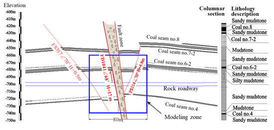
Figure 1.
Profile map of the rock strata.
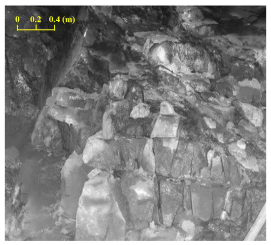
Figure 2.
Image of the exposed dense fractures in the fault zone.
The rock mass in this fault zone is very weak due to its poor integrity. Many roadways under such adverse geological conditions in this coalfield were badly damaged because of the low strength and high tectonic stress of the surrounding rock, as shown in Figure 3. Common supporting methods hardly prevent roadway damage, and so a special supporting strategy is required.
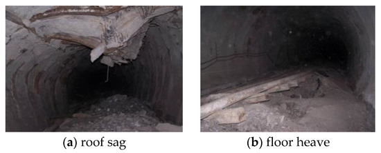
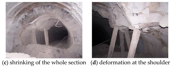
Figure 3.
Typical failure modes of the roadway in faults in this coalfield.
2.2. Mechanical Characteristics of the Surrounding Rock in FD1041
The uniaxial compression test and a conventional triaxial compression test were carried out on sandy mudstone samples collected from the FD1041 fault zone. Testing results demonstrated that the uniaxial compressive strength of the sandy mudstone was approximately 18–25 MPa, while the peak stress increased to 70–90 MPa when loading in confining pressure (20–30 MPa). The tested elasticity modulus was roughly 10–14 GPa, and the Poisson’s ratio was roughly 0.1–0.26. The calculated cohesion and the internal friction angle were approximately 2 MPa and 35°, respectively. Integrity of the rock mass in FD1041 is very poor. Moreover, high tectonic stress and a fault gouge make the surrounding rock more difficult to support.
2.3. Mineralogical Analysis of the Rock in FD1041
In order to analyze the composition of the surrounding rock, a mineralogical analysis test was carried out on the sandy mudstone samples collected from the FD1041 fault zone. Mineral contents of the sample are shown in Table 1. A chemical test showed that the ingredients were mainly SiO2 (53.81%) and Al2O3 (20.69%).

Table 1.
Mineral contents of sandy mudstone.
The hydrophilicity of argillaceous cemented sedimentary rocks is usually obvious. Clay mineral and water content are key factors determining the water softening and expansion behavior of sedimentary rocks. Montmorillonite is a swelling clay mineral with strong water sensitivity, and can expand to several times its original size. Glimmerton is not as expansive as montmorillonite, but it can make rock more brittle and weaker when absorbing water. Kaolinite will not swell, but tends to become soft when absorbing water. Generally, rock is considered to have apparent swell-shrink characteristics when the content of montmorillonite exceeds 7%, or the content of glimmerton exceeds 20%. Therefore, the tested rock samples would become weak and swell slightly when the water content increased. Some of the construction procedures (for example: drilling holes) use water piped from the ground. Effluent water may accumulate on the roadway floor, which is harmful for the rock strength if not drained in time. Thus, drainage procedures should be carried out as soon as possible.
3. Analysis of Geo-Stress State in FD1041 when It Formed
Tectonic stress is a key factor that affects the stability of the surrounding rock in a fault zone. Geological movements lead to an increase in tectonic stress and cause further strata failure when the stress exceeds the strength of the rock mass, and subsequently the fault is formed. It is very hard to test in-situ geo-stress in the extremely fractured zone using current testing methods. So, we tried to analyze the stress state of the surrounding rock in the FD1041 fault zone based on the Mohr failure theory, which is widely used for materials that yield when subjected to shear loading.
Geological exploration reports showed that the FD1041 is a thrust fault, and its formation is mainly attributed to horizontal squeeze. The mechanical model was generalized according to the geological features of FD1041, as shown in Figure 4. Shear failure occurs along the sliding face and plastic yielding occurs when rock mass is squeezed by tectonic movement near the horizontal direction. The following assumptions were made to facilitate the research work: (1) the rock in each rock strata were homogeneous and isotropic before the fault formed; (2) the vertical stress was mainly associated with the gravity of the overlying strata; (3) the failure criterion for the rock mass fitted the Mohr theory; (4) the maximum stress occurred in sandy mudstone when failure occurred.
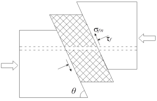
Figure 4.
Mechanical model for FD1041.
The rock elements stayed in the three-dimensional stress balance state before failure occurred. The stress state changed when tectonic movement happened. According to the Mohr failure theory, the normal stress components on the failure face can be given as:
where τfc and c represent the shear strength and cohesion of the rock, respectively; is the normal stress on the shearing plane; f is the internal friction coefficient of the rock, and ; and φ is the internal friction angle.
The yield stress depends on the major and minor principal stresses according to the Mohr failure theory. Normal and shear stresses on the failure plane can be expressed as:
where and are the major and minor principle stressors, respectively; is the angle between and the normal direction of the failure plane; and is shearing stress on the failure plane.
The Mohr failure theory indicates that αf = 45° + φ/2, where is the angle between and the normal direction of the failure plane. The cohesion of intact sandy mudstone is c = 2.0 MPa and the internal friction angle φ = 42°. Therefore, αf = 45° + φ/2 = 66°. As shown in Figure 5, the angle between and horizontal plane is calculated as: 68° − 24° = 44°. The direction of (intermediate principal stress) is parallel to the fault strike, which is NW60°.
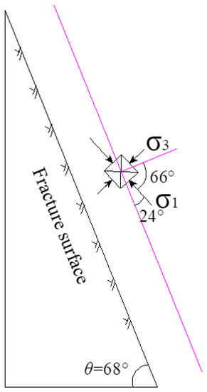
Figure 5.
Initial direction of principle stresses near the major fault.
Then, the normal stress and shear stress on the failure plane can be expressed as:
With the evolution of the tectonic stress induced by tectonic movement, the shearing stress on the plane would increase gradually. The critical failure condition can be given as:
Thus, we can get:
Then,
Vertical stress is mainly associated with the gravity of the overlying strata. According to a previous geo-stress test using a stress-relieving method near the fault zone in this coalmine, the vertical stress of the surrounding rock in the fault zone was approximately 19 MPa.
Thus, the vertical stress component can be calculated as:
So,
From Equations (8) and (10), we can get = 34.02 MPa and = 4.97 MPa. The horizontal stress component perpendicular to the fault strike can be expressed as:
Thus, the horizontal shear stress can be written as:
The Mohr stress circle for the sandy mudstone stratum is shown in Figure 6.
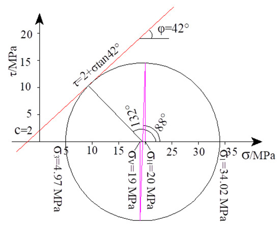
Figure 6.
Mohr stress circle for sandy mudstone when failure occurred.
The results from the above analysis roughly describe the stress state of the sandy mudstone layer when the fault initially formed. The horizontal tectonic stress could change as result of a long period of tectonic movements.
4. Numerical Simulation
4.1. Model Construction and Calculation Procedure
An important aspect of geo-mechanical analysis and designing is the application of supporting strategies to stabilize the fractured rock mass. Supporting strategies should act to conserve inherent rock mass strength so that its self-supporting ability can be enhanced. In this research, the stability of roadway excavation under in situ conditions and assessment of the effect of support measures were simulated by 3DEC, which is a three-dimensional numerical program based on the distinct element method. It can simulate the response of discontinuous rock mass subjected to either static or dynamic loading. The fractured rock mass was represented as an assemblage of discrete blocks. The discontinuities were treated as boundary conditions between blocks. Large displacements along the discontinuities and rotations of blocks were allowed in this software [20]. It is applicable for simulating the deformation behavior of rock masses in fault zones.
According to the profile map of the rock strata, the model was built with the size of 80 × 80 × 80 m, as shown in Figure 7. The model contained two paralleled major faults, dipping at 68° and the dip direction was 190°. The roadway was horseshoe-shaped (semi-circular roof and straight wall, 4.3 m in height and 5.6 m in width). It was centered along the y-axis of the model, and was roughly perpendicular to the fault strike. The origin of coordinates (x = 0 m, y = 0 m, z = 0 m) was set at center of the model.
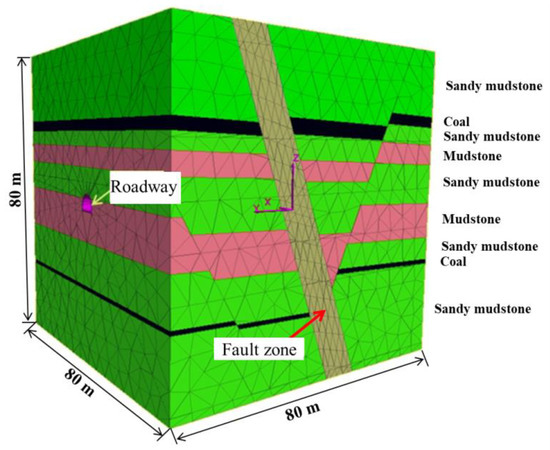
Figure 7.
Calculation model.
It was very difficult to determine the precise locations of the interfaces due to the intrusion of different rock strata. The elements in the fault zone were separately defined. The discrete joints were treated as several sets of paralleled and crossed planes. The joints were generated via a built-in command of the software. As we mainly focused on the stability of the surrounding rocks in the fault zone, the joints in the non-fault zones were not considered, except for the interfaces between the strata.
The rock type mainly contained sandy mudstone, coal, and mudstone. The rock block zone in this model was considered as an elastoplastic medium, and the Mohr-coulomb model was adopted to describe its mechanical behavior. It is a conventional model used to represent the shear failure in soils and rocks. It was very difficult to obtain the precise mechanical parameters of the interfaces due to the extremely complex geological conditions in the fault zone. The main mechanical parameters of the rocks were assigned mainly according to the mechanical tests, while the parameters of the interfaces were determined based on previous research [20,21,22,23]. The main mechanical parameters of the model are listed in Table 2, and the mechanical properties of the joints are listed in Table 3. The main parameters of the structure elements (bolts and cables) are listed in Table 4 and Table 5 [20]. The maximum unbalanced force was monitored to identify an initial equilibrium stress state, which was reached before excavation. The displacements of the model were reset to zero before the excavating procedure.
Table 2.
Main parameters of the model.
Table 3.
Main mechanical parameters of the joints.
Table 4.
Main parameters of the bolts in the model.
Table 5.
Main parameters of the cables in the model.
The stress boundary was set according to the stress testing result near the fault zone, and the analysis on the stress field of this zone. The vertical in situ stress on the top boundary was set to 19 MPa, while the horizontal stresses parallel and perpendicular to the roadway were set to 28 MPa and 15 MPa, respectively. The displacement boundary condition was defined as follows: (1) the bottom boundary of the model was fixed to restrict vertical displacement; (2) the top boundary was free; and (3) the side boundary was fixed to restrict horizontal displacement.
4.2. Calculation Support Strategies
The stability of the roadway under different supporting conditions was calculated and compared. Ordinary support strategies in the coal mine were firstly calculated and compared with the real deformation conditions of roadways in similar geological conditions. Then, an improved support strategy was calculated. The following calculation results mainly focus on the displacement fields of the surrounding rock.
(1) Method I (ordinary support strategy): bolts, cables, and lining composed of U-steel and shotcrete.
This support strategy had been applied in previously excavated roadways passing through the FD1041 fault zone. As shown in Figure 8, the ordinary supporting structure contained bolts, cables, and lining (composed of U-steel support and shotcrete, the grade of steel was 20 MnK with tensile strength > 490 MPa, yielding strength > 335 MPa, and elongation > 16%). The diameter and length of the bolts were 22 mm and 2.5 m, respectively. Interval space was set to 0.8 × 0.8 m. The diameter of the cables was 22 mm, and the length was 6.3 m. The row distance of the cables was 2.4 m. The floor was reinforced by three cables in each section, and the row distance was set to 2.4 m. Pre-forces of bolts and cables were set to 20 kN and 180 kN, respectively.
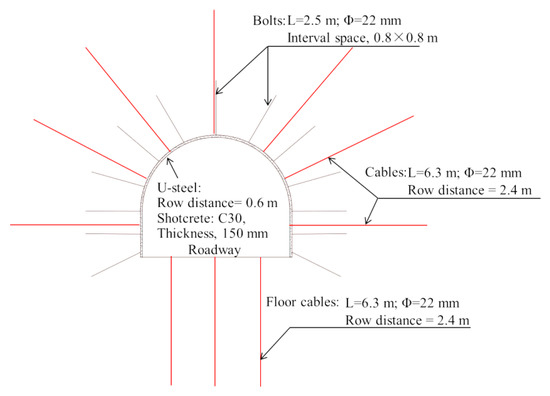
Figure 8.
Ordinary support system.
(2) Method II (Improved Method): long pipe pre-grouting, bolts, cables, and lining made of U-steel and shotcrete.
The supporting structure of the improved support system is shown in Figure 9. Pre-grouting was introduced in the improved supporting method. Broken rock mass in the fault zone was reinforced by pre-grouting prior to excavation. The hexahedron zone with size of 30 × 30 × 15 m was treated as the grouted region (Figure 10). It was assumed that the cracks in the grouted block were fully filled by cement paste. The mechanical properties of the grouting block were enhanced compared with the non-grouted blocks. Mechanical parameters of the pre-reinforced rock elements and joints were assigned according to Table 2 and Table 3. The row distance of the cables was changed to 1.8 m, and the length of the cables in the roof and floor was lengthened to 8.3 m and 7.3 m, respectively.
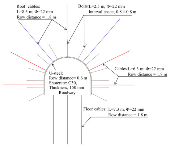
Figure 9.
The supporting structure of the improved support system.
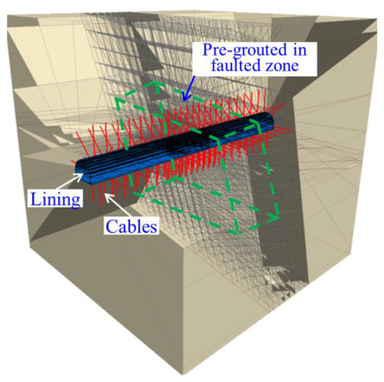
Figure 10.
Sketch of the pre-grouted zone in the calculation model (bolts are hidden).
4.3. Calculation Results
4.3.1. Results of Method I (Ordinary Support Strategy)
The calculation of the displacement field of the roadway is shown in Figure 11a,b, indicating that the roadway deformation was large. Vertical displacement showed that the roof sag exceeded 500 mm, while the floor heave exceeded 350 mm. Figure 9 plots the vertical displacement of the surrounding rock in the fault zone, indicating discontinuous features of the displacement field. It can be attributed to the failure of interfaces between rock blocks.
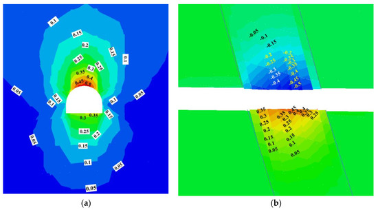
Figure 11.
Calculation results of the roadway displacement using method I (Unit: m): (a) three-dimensional diagram in the fault zone; (b) vertical displacement on slice plane x = 0.
The thickness of the loose zone in the roof and floor exceeded 10 m. Bolts and cables could not achieve optimal load-carrying performance in this condition. The roadway stability could not be controlled using the ordinary support system, which was also verified by monitoring the results of the previously excavated roadways in this fault zone (Figure 12). We could see that the monitoring displacement continued to rise gradually during the 160 days following the excavation. The maximum roof sag exceeded 500 mm, and the floor heave reached nearly 300 mm.
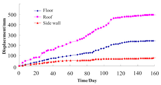
Figure 12.
Monitoring displacement curve using the ordinary support system.
4.3.2. Results of Method II (Improved Method)
Figure 13 plots the roadway displacement in the fault zone using the improved supporting strategy. The results showed that the displacement reduced significantly compared with the ordinary method. The maximum displacement was about 200 mm. Moreover, the displacement curves became smoother than when using the ordinary support system, indicating that the shearing displacement between the rock blocks in the fault zone became smaller.
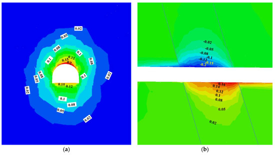
Figure 13.
Calculation results of the roadway displacement using the improved support method (Unit: m): (a) the displacement on the slice plane y = 0; (b) the vertical displacement on the slice plane x = 0.
The improved support system was implemented in the experimental roadway, and the displacement of the roadway was monitored. Typical monitoring displacement curves are shown in Figure 14. We observed that the maximum displacement of the roof, floor, and sidewall was approximately 210, 140, and 50 mm, respectively. This is satisfactory for roadways in such unfavorable geological conditions.
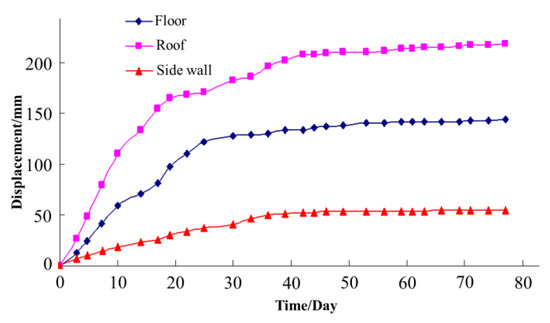
Figure 14.
Monitoring displacement curve using the improved support system.
5. Conclusions
The stability of roadways passing through fault zones of coalmines is affected by many factors, including tectonic stress, dense fractures, low strength of the rock mass, etc. A roadway in the FD1041 fault zone of China’s Gugui coalfield was investigated. Geo-stress characteristics in the fault zone were analyzed based on Mohr failure theory. The stability conditions of the roadway using ordinary and improved supporting methods were calculated using a numerical program based on the distinct element method. The calculation results showed that the surrounding rock was seriously damaged under the ordinary supporting method, which was also verified by monitoring the results of the previously excavated roadways in this fault zone. The calculation results for the improved supporting method showed a satisfactory effect. The monitoring results of the experimental roadway also indicated that a massive deformation had been successfully avoided using the improved strategy, which proved to be an effective method for the roadway in this fault zone.
In engineering practice, grouting is considered an effective method to reinforce fractured rock mass. However, there are few numerical simulation studies that focused on the pre-grouting effects in the fault zone of a coalmine. We tried to simulate the stability conditions using an improved support system, in which the pre-grouting effect is considered. Pre-grouting proved to be an effective method to reinforce the fractured rock mass in the fault zone. The simulation results showed that pre-grouting can significantly enhance the strength of fractures and resist shearing deformation. Thus, pre-reinforced rock mass can facilitate the stability of roadways after excavation.
Author Contributions
Conceptualization, Y.K. and B.L.; methodology, Y.K. and C.H.; software, C.H.; validation, J.L.; formal analysis, C.H.; investigation, J.C.; resources, B.L.; data curation, Z.G.; writing—original draft Y.K.; writing—review and editing, C.H.; visualization, J.L.; project administration, B.L. All authors have read and agreed to the published version of the manuscript.
Funding
This research was funded by the funding of National Natural Science Foundation of China, grant number 51774267; Youth Innovation Promotion Association CAS, grant number 2017377.
Institutional Review Board Statement
Not applicable.
Informed Consent Statement
Not applicable.
Data Availability Statement
Some or all data, models, or code that support the findings of this study are available from the corresponding author upon reasonable request.
Acknowledgments
The authors gratefully acknowledge the financial support provided by the Natural Science Foundation of China (No. 51774267), and Youth Innovation Promotion Association CAS (No.2017377).
Conflicts of Interest
The authors declare no conflict of interest.
Notation
The following symbols are used in this paper:
| τfc | shear strength |
| c | cohesion of rock |
| normal stress on the shearing plane | |
| F | internal friction coefficient of the rock |
| φ | internal friction angle |
| major principle stress | |
| intermediate principal stress | |
| minor principle stress | |
| the angle between and the normal direction of the failure plane | |
| shearing stress on the failure plane | |
| E | Young’s modulus |
| K | Bulk modulus |
| G | Shear modulus |
| ν | Poisson’s ratio |
References
- Bellis, M.L.; Vecchia, D.; Ortiz, M.; Pandolfi, A. A linearized porous brittle damage material model with distributed frictional-cohesive faults. Eng. Geol. 2016, 215, 10–24. [Google Scholar] [CrossRef]
- Elizalde, C.; Griffith, W.A.; Miller, T. Thrust fault nucleation due to heterogeneous bedding plane slip: Evidence from an Ohio coal mine. Eng. Geol. 2016, 206, 1–17. [Google Scholar] [CrossRef]
- Fei, Y.; Liu, S.Q.; Xu, Y.C.; Zhao, L. Failure Analysis of Thin Bedrock and Clay Roof in Underground Coal Mining: Case Study in Longdong Coal Mine. Int. J. Geomech. 2020, 20, 04020187. [Google Scholar] [CrossRef]
- Cui, C.; Gratchev, I. Effects of pre-existing cracks and infillings on strength of natural rocks—Cases of sandstone, argillite and basalt. J. Rock Mech. Geotech. Eng. 2020, 12, 1333–1338. [Google Scholar] [CrossRef]
- Tetsuya, T.; Kimikazu, T.; Eiichi, I. Influence of a fault system on rock mass response to shaft excavation in soft sedimentary rock, Horonobe area, northern Japan. Int. J. Rock Mech. Min. Sci. 2011, 48, 773–781. [Google Scholar]
- Marinos, V. Roadway behaviour and support associated with the weak rock masses of flysch. J. Rock Mech. Geotech. Engin. 2014, 6, 227–239. [Google Scholar] [CrossRef]
- Kang, Y.; Liu, Q.; Xi, H. Numerical analysis of THM coupling of a deeply buried roadway passing through composite strata and dense faults in a coal mine. Bull. Eng. Geol. Environ. 2014, 73, 77–86. [Google Scholar] [CrossRef]
- Bieniawski, Z.T. Geomechanics Classification of Rock Masses and Its Application in Tunneling. In 3rd Congress of the International Society of Rock Mechanics; Denever National Academy of Sciences: Washington DC, USA, 1974; pp. 27–32. [Google Scholar]
- Bieniawski, Z.T. Engineering Rock Mass Classifications; John Wiley & Sons: Hoboken, NJ, USA, 1989; p. 251. [Google Scholar]
- Barton, N. Some new Q-value correlations to assist in site characterization and roadway design. Int. J. Rock Mech. Min. Sci. 2002, 39, 185–216. [Google Scholar] [CrossRef]
- Barton, N.; Lien, R.; Lunde, J. Engineering classification of rock masses for the design of roadway support. Rock Mech. 1974, 6, 189–239. [Google Scholar] [CrossRef]
- Palmström, A. RMi-A Rock Mass Characterization System for Rock Engineering Purposes. Ph.D. Thesis, University of Oslo, Oslo, Norway, 1995. [Google Scholar]
- Palmström, A. Recent developments in rock support estimates by the RMi. J. Rock Mech. Roadway Technol. 2000, 6, 1–19. [Google Scholar]
- Huang, Q.X.; Wang, X.F.; Chen, X.Y.; Qin, D.D.; Chang, Z.C. Evolution of Interior and Exterior Bearing Structures of the Deep-Soft-Rock Roadway: From Theory to Field Test in the Pingdingshan Mining Area. Energies 2020, 13, 4357. [Google Scholar] [CrossRef]
- Gurocak, Z. Analyses of stability and support design for a diversion roadway at the Kapikaya dam site, Turkey. Bull. Eng. Geol. Environ. 2011, 70, 41–52. [Google Scholar] [CrossRef]
- Gurocak, Z.; Solanki, P.; Zaman, M.M. Empirical and Numerical Analyses of Support Requirements for a Diversion Roadway at the Boztepe dam site, Eastern Turkey. Eng. Geol. 2007, 91, 194–208. [Google Scholar] [CrossRef]
- Kanik, M.; Gurocak, Z.; Alemdag, S. A comparison of support systems obtained from the RMR89 and RMR14 by numerical analyses: Macka Roadway project, NE Turkey. J. Afr. Earth Sci. 2015, 109, 224–238. [Google Scholar] [CrossRef]
- Kaya, A.; Bulut, F. Stability analyses of roadways excavated in weak rock masses using empirical and numerical methods. J. Geol. Eng. 2013, 37, 103–117. [Google Scholar]
- Yang, S.Q.; Chen, M.; Jing, H.W.; Chen, K.F.; Meng, B. A case study on large deformation failure mechanism of deep soft rock roadway in Xin’An coal mine, China. Eng. Geol. 2017, 217, 89–101. [Google Scholar] [CrossRef]
- Itasca Consulting Group, Inc. 3 Dimensional Distinct Element Code (3DEC) user’s Guide; Itasca Consulting Group, Inc.: Minneapolis, MN, USA, 2005. [Google Scholar]
- Tang, Z.C.; Liu, Q.S.; Xia, C.C. Mechanical Model for Predicting Closure Behavior of Rock Joints Under Normal Stress. Rock Mech. Rock Eng. 2014, 47, 2287–2298. [Google Scholar] [CrossRef]
- Sandbak, L.A.; Rai, A.R. Ground support strategies at the turquoise ridge joint venture, Nevada. Rock Mech. Rock Eng. 2013, 46, 437–454. [Google Scholar] [CrossRef]
- Shi, C.; Yang, B.; Zhang, Y.P.; Yang, J.X. Application of discrete-element numerical simulation for calculating the stability of dangerous rock mass: A case study. Int. J. Geomech. 2020, 20, 04020231. [Google Scholar] [CrossRef]


Publisher’s Note: MDPI stays neutral with regard to jurisdictional claims in published maps and institutional affiliations. |
© 2021 by the authors. Licensee MDPI, Basel, Switzerland. This article is an open access article distributed under the terms and conditions of the Creative Commons Attribution (CC BY) license (https://creativecommons.org/licenses/by/4.0/).