1. Introduction
Expansion of renewable generation is one of the main targets of most countries in the modernization of the electricity industry [
1]. The competition is not only on the power capacity level of such generation units, but also another key trend is the development of operation technologies for enhanced adaption with the rest of the grid [
2]. There is a consensus that the goal of the international organizations is to achieve double the capacity of current renewable generation. This competition is expected to be more intense during the forthcoming years [
3].
Increasing the capacity of each renewable generation unit, as well as using of control technologies that facilitate high adaptation flexibility with rest of the grid are two main factors in the renewable generation expansion [
4]. Nowadays, the researchers are trying to expand this adaptability from both technical and economic point of view [
5]. From the technical point of view, grid operators expect that renewables should not only have proper adaptability with the classic part of the system, but it is also expected to solve some challenges of the power grid [
6]. Some of the expected challenges include the contribution of renewables in the stability of power network, such as power and frequency stability [
7], as well as voltage and reactive power support [
8].
From the power and frequency point of view, the contribution of high-power renewables (multi MW capacity) has been of great interest from the grid operators perspective [
9]. This is due to the implementation of modern control technologies in renewable generation units [
10] that have provided multi-degrees of dynamics-electric flexibilities which aids stability support of the power grid [
11]. Such control technologies rely on non-synchronous generators to mimic the characteristics of conventional synchronous generators. These electronic generators generally have been called Static Synchronous Generators (SSG), Virtual Synchronous Machine (VSM) [
12,
13], Virtual Synchronous Generator (VSG) [
14], or synchronverters [
15,
16].
In some cases, a renewable power plant has been equipped with new control technologies which can provide the required dynamic response for the power grid. Thus, these power plants can support the frequency criteria and power stability of the interconnected generation areas [
17]. Furthermore, the synchronism of generation units can be supported in this situation [
18]. Besides these modern control technologies, mobilization of renewables with other new technologies such as supercapacitors or energy storage systems supports the frequency conditions in the isolated grid [
19]. Moreover, it has been shown that such technology can support the stability of multi machine systems [
20].
In addition to the growth in power level of renewables, the emulation of the characteristics of conventional synchronous generator in control layers of modern renewables is another main developed feature. This dynamic development makes renewables a key player in the dynamic performance of power grid. The Synchronous Power Controller (SPC) technique is one of the effective control novelties for synchronous emulation which has been presented in [
21]. The implementation of a SPC is very similar to the electrical-electromechanical characteristics of synchronous generator providing the capability of dynamic parameters such as virtual admittance, virtual damping, and virtual moment of inertia in control of power converters. From the electrical circuit point of view, the virtual admittance can support power-sharing between the parallel power converters [
22,
23,
24]. Moreover, from the electromechanical point of view, HVDC interline systems can be supported by the SPC technique to enhance important dynamic modes [
25]. Additionally, the expansion of SPC-based renewables is possible in the power grid where the renewable power plants have several structures [
26].
Furthermore, in [
27,
28] we have shown that the mixed electrical-dynamics capabilities of SPC technique can support the stability of long lines in HVAC transmission systems. These capabilities can be used to support the required frequency condition in interconnected generation areas [
29].
All of the mentioned research work confirm that the operation of renewables based on SPC technique has a high potential future for the great adaptability with an external power grid. This type of the enhanced renewable generation unit can support the expansion of green generation in the power network by following the grid codes to satisfy the grid operator’s requirements. However, the challenging and essential part of using such electrical-dynamic capabilities of the SPC technique to support stability of power grid is that the electro-mechanical section of SPC must be designed and controlled through careful considerations to the characteristic of the external power grid. This essential point has not been covered in the related previous work. Therefore, an organized and sequenced method for electromechanical design of Renewable Static Synchronous Generators controlled by SPC (RSSG-SPC) in grid application has been proposed briefly in [
30]. Later, this methodology has been expanded and investigated from several points of the view in [
31].
This paper aims to target three main goals: (i) a deep review and analysis of the electromechanical performance of RSSG-SPC, (ii) proposal of solution for enhanced adaption of RSSG-SPC operation in the grid connection to facilitate the contribution of RSSG-SPC in the power-sharing process as well as frequency regulation, and (iii) proposal of a regular and coherent pattern as well as the mathematical expressions for the electromechanical design of power converter controllers in the grid connection of RSSG-SPC for an efficient contribution in the power grid stability support.
This paper is organized as follows: In
Section 2, the grid connection of RSSG-SPC is explained with a proposal of possible solution for enhancement of this condition. In
Section 3, the internal dynamics of RSSG-SPC were analyzed to realize the dynamic capabilities provided by the virtual damping and virtual inertia.
Section 4 discusses the dynamic modeling of the external power grid in presence of RSSG-SPC taking into consideration the electrical model of RSSG-SPC. In this section, the clear mathematical expressions to define electrical-dynamical effects of RSSG-SPC in the grid equations are formulated. This is followed by
Section 5 where the proposed algorithm was utilized to evaluate and analyze the performance of RSSG-SPC in a IEEE 14B benchmark based on the dynamic modeling and modal analysis technique. This section explains that an RSSG-SPC designed based on the proposed dynamic equations, can support the damping and power and frequency stability of power grid. In
Section 6 and
Section 7, an evaluation of the proposed method and equations was preformed to check the validity and trustworthiness of the dynamic analysis outcomes. In these sections, the required tests were conducted in the time domain for IEEE 14B benchmark using Simulink model as well as real-time laboratory tests.
2. Structure and Control of RSSG-SPC
As discussed in [
30], the global structure and internal control unit of RSSG-SPC can illustrated as in
Figure 1. As a renewable generation unit, the primary source of RSSG-SPC can be supplied from several types of the sources such as wind, solar, and energy storage systems. Extracted energy would be injected into external power grid after passing the power filter and a step-up coupling transformer.
The active and reactive power control would be achieved by SPC as a sub-unit in the control algorithm. In SPC, after measuring the instantaneous active and reactive power (
,
), tuning the reference values of the active power (
), frequency (
), and internal voltage (
) by the operator, then the reference signal (
) would be defined for virtual admittance sub-unit. The virtual admittance converts the voltage reference to the current reference (
), and this new reference is first checked to be within the limits of the converter and then passed on to a Proportional Resonant (PR) current controller. Finally, the PR controller as an internal layer of the controller would provide three phase voltage references (
) for the PWM module to drive the converter switches. Further details concerning the control layers has been extensively discussed in [
30,
32].
In the grid connection of RSSG-SPC, the implementation of electromechanical part is essential since it is core of the SPC to enable control of the voltage source converter efficiently. Aside from tuning the virtual damping (D) and virtual inertia (H), which will be discussed in depth in the next Section, the structure of the electromechanical part must be sufficiently adaptable to the real conditions of external power grid. Such conditions can be demonstrated in the external power grid steady state error around the ideal value (). This frequency error is usually not fixed and may differ according to the operating point of external power grid. Although one of the major benefits of an SPC is the frequency detection without the requirement of a Phase Locked Loop (PLL), the existence of such a steady state frequency error can interrupt the frequency detection process which would eventually affect the converter capability to follow the power reference.
One of applicable methods for the implementation of electromechanical part is shown in
Figure 2. This structure considers the real frequency conditions of the power grid to acquire an adaptable electromechanical block with the mentioned frequency error. As shown in
Figure 2, a first order high pass filter (1HPF) has been used in the feedback loop to avoid such frequency error. In the absence of 1HPF, the active power error (
) would be affected through the damping coefficient (
) if the frequency error (
) does not reach to zero (as result of
). With the existence of a steady state frequency error,
will not been followed accordingly by the SPC loop which eventually means
as result of
. However, using a designed 1HPF, this dc error in frequency can be eliminated from the SPC loop without causing any interruptions in the performance of the electromechanical part. It should be noted that during the tuning process of 1HPF, the electromechanical part should be capable of achieving proper dynamic response as well as provides sufficient damping effect on the electromechanical oscillations. Nevertheless, the virtual inertia and virtual damping are the main duties of RSSG-SPC in grid application and these advantages should not be affected by the 1HPF.
To tune 1HPF, it is necessary that all of oscillatory
with a frequency in range of the typical electromechanical oscillations (
) must be passed through the feedback link having the maximum gain (close to 1) and the minimum phase shifting (close to zero) in 1HPF as depicted in
Figure 3. In a typical operation area of a grid application, these oscillations are in range of (
) and higher [
33]. Usually, oscillations in range of (
) are related to the inter-area oscillations and higher frequencies (
) are linked to the local oscillations inside of generation areas [
33].
Therefore, considering a proper safety margin for the worst-case scenario, the 1HPF can be tuned to have sufficient quick response during operation. As an example, in
Figure 3 a 1HPF with time constant (
) will pass the
oscillations by gain magnitude
and phase shifting of
. This tuning will provide a good safety margin for oscillations with frequency of (
), where the gain magnitude is
and phase shifting is
in oscillation frequency of
.
A higher safety margin requires a lower cut-off frequency in 1HPF () which also means a higher time constant () leading to slower dynamic response. Since the output signal of the filter will affect directly, therefore the dynamic response of the filter will affect the time for the system to arrive to zero frequency error or zero power error. Thus, the slower dynamics of filter will slow down the SPC loop to settle in a new steady state operating point.
Considering the dynamic response of electromechanical part while excluding the effect of the 1HPF usually results with less than one second time response as result of
and
tuning [
27,
28,
29]. However, in presence of this filter, in the response shown in
Figure 4 achieves 2% settling time in
with the filter tuned on
. Therefore, in such a filter tuning case, time domain analysis of grid connection must be done in
intervals to ensure the capability to capture the new operating point of RSSG-SPC.
Tuning of the 1HPF is a trade-off between the frequency response (i.e., having sufficient safety margin to damp all oscillatory electromechanical modes by
, as illustrated in
Figure 3) and time response (i.e., having a fast response to satisfy grid code requirements and grid operators command during grid connection, as shown in the step response in
Figure 4).
The contribution of RSSG-SPC in primary frequency control is another topic that is important from the grid operators. This feature is essential for large-scale renewables to enhance their adaptability with the rest of the power grid. Moreover, it is important to follow the grid operators’ requirements in frequency regulations. A power-frequency droop controller as the auxiliary layer can be added to SPC sub-unit to satisfy this requirement as depicted in
Figure 5.
The frequency error (
) shown in
Figure 5 is passed through a droop gain (
). Later, the corrective active power signal () with proper delay is added to reference power (
) which has been defined by operator. Therefore, the final power reference (
) would be modified for RSSG-SPC contribution in the primary control of frequency.
Dynamic decoupling of the droop controller operation and SPC loop performance will secure the operation of RSSG-SPC to frequency support as well as to dampen oscillations in the grid application. This decoupling would be controlled through the design of delay block and proper selection of delay time constant (). Usually, if this delay is ten times slower than SPC loop (), then the expected performance of RSSG-SPC would be satisfactory for primary control of frequency as well as for damping oscillations by the electromechanical part. Therefore, for the electromechanical block tuned at and , a delay time constant would be sufficient to decouple both dynamics.
3. Internal Dynamics of RSSG-SPC
From the external power grid side, an RSSG-SPC can be analyzed from tow technical viewpoints: (i) electromechanical performance and (ii) electrical characteristics (see
Section 4). From the electromechanical point of view, due to the utilization of SPC technique and especially electromechanical block, the internal dynamics of RSSG-SPC can be analyzed as depicted in
Figure 6 and expressed in Equations (1)–(6). Based on the
Figure 6, the internal dynamics of RSSG-SPC has two degrees of dynamic freedom which provides the required dynamics for emulation of synchronous generator through voltage source converters inside the RSSG-SPC.
Equation (1) presents the mathematical expression of internal dynamics. The
is synchronization power with the external system and it can be calculated using Equation (2) where
is power angle at initial operating point,
is nominal frequency, and
is interconnected reactance. Equation (3) gives the internal modes of RSSG-SPC (
). As discussed in [
30], RSSG-SPC’s dynamic parameters provide high flexibility inside the RSSG-SPC that can be targeted for several applications in grid connection.
Having flexible virtual damping (
) is the minimum degree of dynamic freedom that yields a strong capability for damping of oscillations.
Figure 7 shows the effect of flexible
on internal dynamics of RSSG-SPC. Increasing the stability margin in the internal modes (
) as well as reducing the frequency of internal oscillations are the main effects of
reinforcement. This capability enables RSSG-SPC to adapt itself with a wide range of the dynamics of external power grid through the control of frequency in internal modes. Moreover, RSSG-SPC can control its internal stability for each grid application case.
The complete freedom to tune
provides the capability to grid operators to target several goals in the grid connection of RSSG-SPC. If a fully damped internal dynamics (
) is targeted,
can be tuned using Equation (5). As shown in
Figure 7, for a system with
,
,
,
, and
, this fully damped condition happens when
.
However, in the grid application of renewables equipped with flexible dynamics such as RSSG-SPC, the grid operators usually request renewables to contribute in damping frequency oscillation as well as suppress power oscillation of power grid. Following this requirement necessitates the ability to provide proper dynamics flexibility inside the RSSG-SPC and a proper level of the internal RSSG-SPC damping. The internal dynamic flexibility of RSSG-SPC is realized in the sense that RSSG-SPC must have sufficient dynamic interaction with external power grid in response to dynamic oscillations inside the external power grid. From the internal RSSG-SPC standpoint, this means
should not be completely damped (
). Moreover, RSSG-SPC must have a proper level of internal damping ratio (
) to share it with external power grid during the dynamic interaction. In this condition, RSSG-SPC can act as an efficient damper for oscillations of external power grid. The primary experience presented in [
29] and [
31], shows that having
for internal modes of RSSG-SPC can provide such appropriate tuning from external power grid point of view.
Theoretical background of RSSG-SPC dynamic tuning can be explained using the general response of second order system as depicted in
Figure 7. In the tuning of
, there are three main characteristics that can be useful for RSSG-SPC contribution in the external power grid oscillations and damping. These characteristics are as follows:
- (i)
are oscillatory. This means RSSG-SPC is not completely stiff from the dynamic point of view, therefore RSSG-SPC can act as a strong dynamic damper, as well as it can respond to oscillations inside the external power grid.
- (ii)
has a significant level of damping ratio (). This means the internal dynamics of RSSG-SPC has enough damping and it can share damping with the external power grid. This also means this dynamic damper is strong enough.
- (iii)
The dynamic modes are in the condition that RSSG-SPC’s time response is acceptable for control and damp the oscillations. This means the electromechanical parts has a fast reaction to the oscillation in the external power grid.
Considering the system presented in
Figure 7, this condition has occurred when
(
), where
had sufficient stability margin. Equations (1)–(5) indicate that the internal dynamics of the RSSG-SPC would be affected by variations in an external power grid which is due to the frequency deviations (
) as a result of the changing in generation level, or small variation of power grid reactance
due to the operation of breakers in transmission lines. Therefore, considering the practical situations of grid connection in our previous research presented in [
27,
28,
29,
30,
31], a reasonable design consideration is to take a 5% safety margin in tuning
. Therefore, in the grid application of RSSG-SPC illustrated in
Figure 7, the damping range (
) for RSSG-SPC can satisfy the grid operators’ requirements. Reliability of
tuning in this safe margin is validated in the next sections (see
Section 5 and
Section 6).
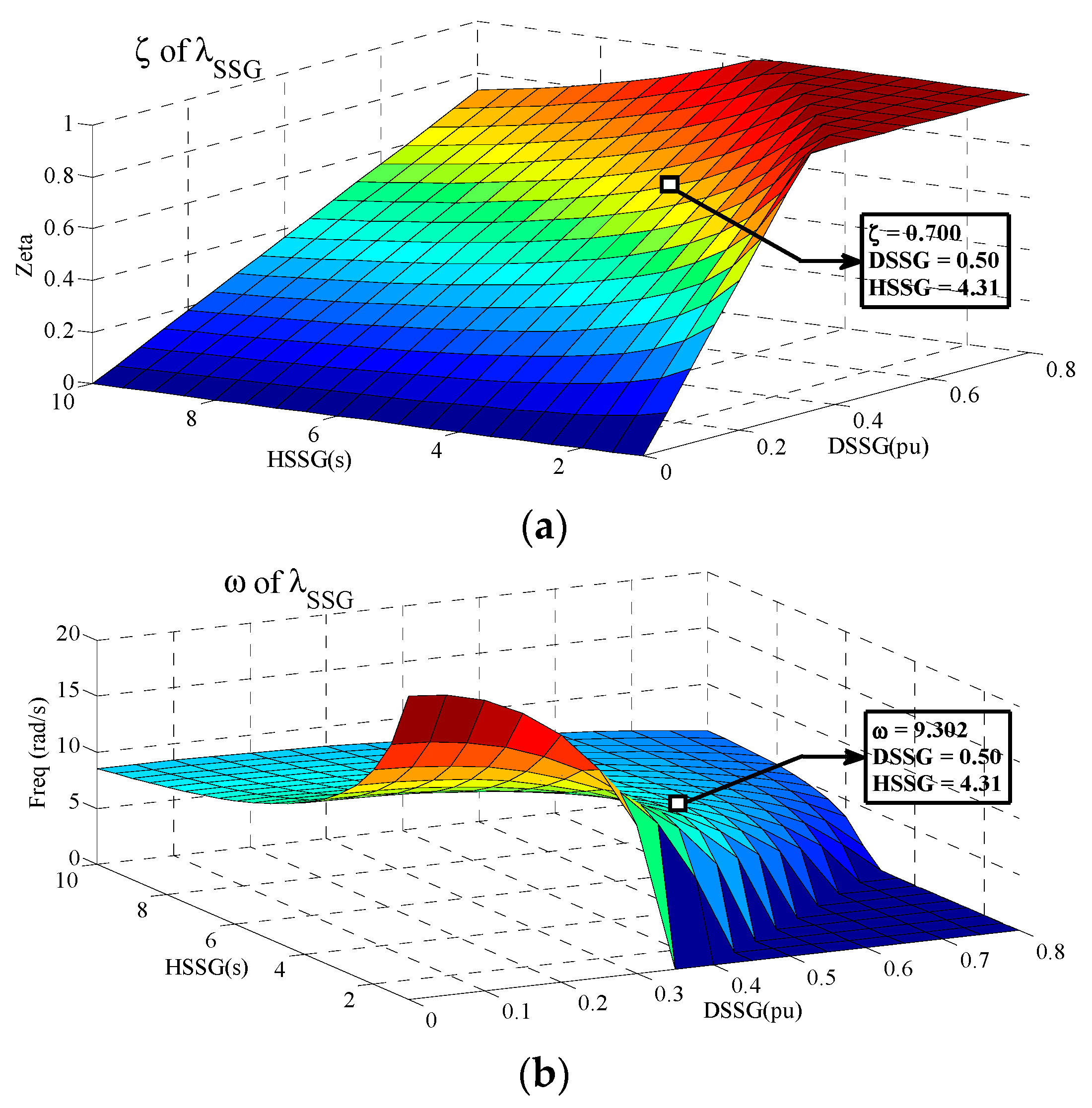
The dynamic flexibility of RSSG-SPC can be analyzed in grid connection on a wider scale through the activation of both dynamic freedoms (
,
). For the system presented in
Figure 7,
Figure 8 shows the level of the damping ratio (
=
of
) and frequency of internal mode (
) in typical operation zone of (
,
—labeled as
DSSG and
HSSG in
Figure 8). Practically, each dynamic tuning of damping and inertia (
,
) is a dynamic operation point of RSSG-SPC on this dynamic surface. The dynamic tuning of system presented in
Figure 7 has been pointed in
Figure 8.
Based on Equation (5) and
Figure 8a, the general structure of
surface confirms that having small values of
, the internal modes of RSSG-SPC (
) would be damped rapidly just by having small value of
. Larger values of
means an RSSG-SPC with stiffer dynamics, which requires a larger value of
to satisfy a specific level of the damping ratio in internal modes (
). The difference in the slope of
surface from small
to large
confirms this concept.
From the frequency (
) point of view,
Figure 8b illustrates the frequency surface characteristics (see Equation (6)) is completely adaptable to
conditions presented in
Figure 8a. In small
zones, the primary level of internal frequency is very high, but it will approach zero quickly and this confirms fast damping of dynamic modes in this zone as well as it proves the weaker dynamics of RSSG-SPC. Moreover, for large
zones, the frequency level is not high while the frequency surface has a smoother slope and finally it will arrive to a semi-flat condition. This means, in large
values, the frequency
will not change significantly due to the variation of
, and this is compatible with the stiffer dynamics of RSSG-SPC in this area.
Therefore, for each grid condition in the Point of Common Coupling (PCC) (,) which has effect on the internal dynamics of RSSG-SPC, the operating point of RSSG-SPC can be tuned and controlled based on these dynamic surfaces. This tuning can be done to cover desired internal dynamic condition of RSSG-SPC such as achieving safe stability margin and proper damping ratio on the internal modes, as well as to achieve the external power grid requirements such as suppressing the power oscillations. Moreover, these figures confirm that RSSG-SPC is highly adaptable to respond to any dynamic changes in the external power grid as well as RSSG-SPC can adapt itself with the new situation in external power grid easily. In other words, RSSG-SPC can adapt itself to the external power grid with a wide range of dynamic characteristics.
4. Small Signal Modelling of Power Network in Presence of RSSG-SPC
In this section, after a quick review on the modeling of RSSG-SPC from external power grid viewpoint, the dynamic modeling of a -buses power network in the presence of RSSG-SPC will be discussed. A detailed model for grid integration of RSSG-SPC will be presented and the main steps for modelling will be summarized. Finally, a systematic methodology will be proposed for a feasible dynamic design of RSSG-SPC.
From the electrical circuit point of view, each RSSG-SPC unit can be considered as a voltage source converter that is operating in current control mode as shown in
Figure 9. From an external grid perspective (PCC viewpoint in
Figure 9), the RSSG-SPC is represented as a current source controlled by the voltage across a virtual admittance (
) that is governed by Equations (7)–(9).
A large power network that contains a combination of classical and renewable generations units (such as RSSG-SPC) and some electrical loads is presented
Figure 10. The input powers (
,
) are supplied from the several kinds of primary sources depending on the type of generation units. To achieve an organized modeling process, all the generation units are assumed to be connected to the first
buses (labeled as PV-buses in
Figure 10), as well as all loads are in the remaining buses from number (
) to
(labeled as PQ-buses in
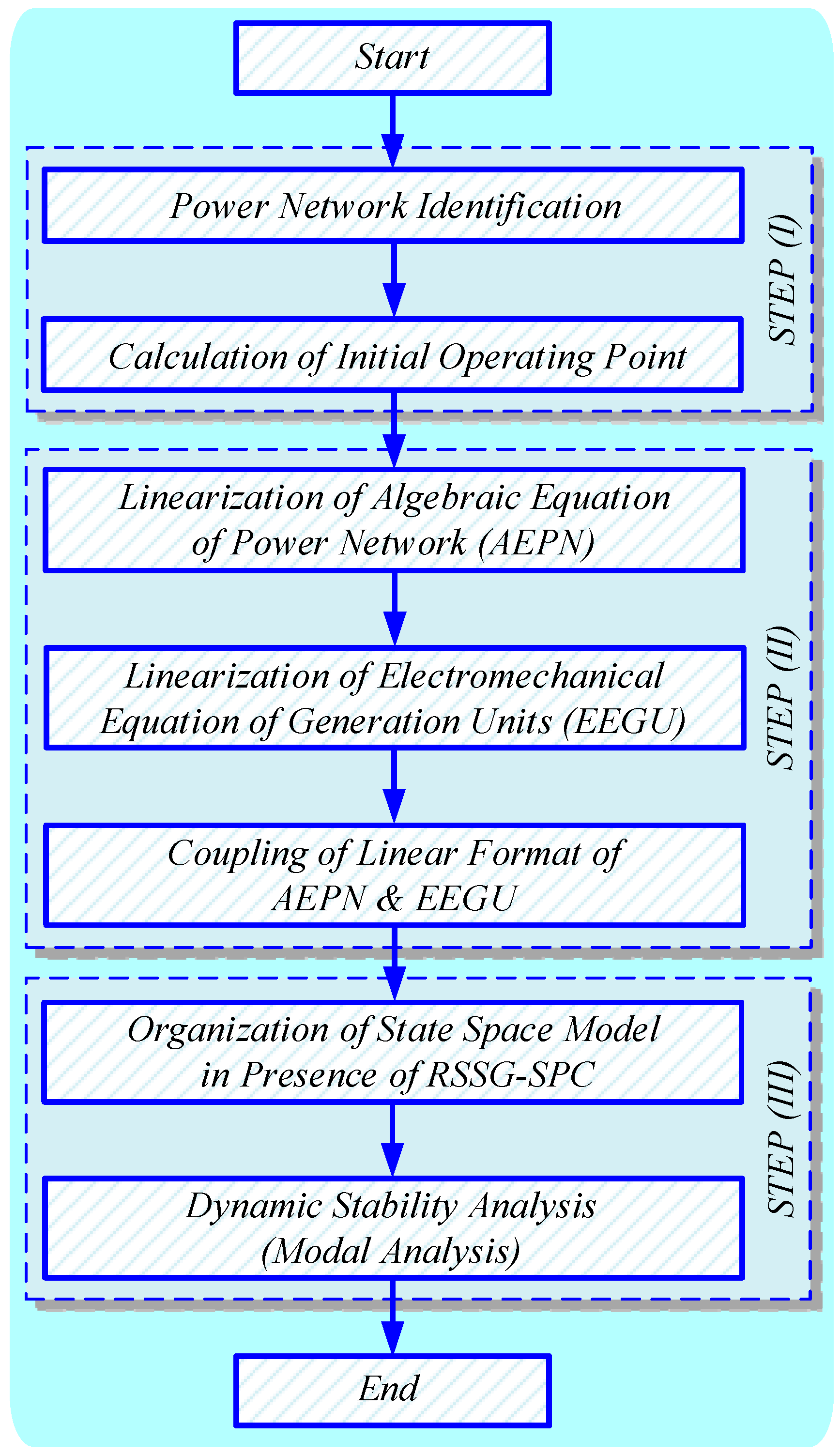
Figure 10). Next, to achieve sequential calculations and a feasible pattern, a flowchart has been proposed for a step-by-step analysis illustrated in
Figure 11. The final goal of proposed methodology is the study of RSSG-SPC’s dynamic effects in the external power network.
There are three steps required for the dynamic modelling of the power network as shown in
Figure 11. In STEP (I), the definition and identification of the power grid as well as extracting the initial operating point are the main goals. In STEP (II), all nonlinear time domain equations of the entire power system including two group of equations, (i) algebraic equations of power network (AEPN), and (ii) electromechanical equations of generation unis (EEGU), are linearized then those group of equations would be combined. Finally, in STEP (III), linearized and combined time domain equations would be transferred to the frequency domain and the state space model of the whole of the system would be formed. In this step, a study of dynamic conditions of the power network in the presence of RSSG-SPC using modal analysis can be achieved [
34]. The detailed mathematical expression of each step is summarized using the main equations as follows:
STEP (I): The aim of this step is to calculate the initial operating point. This is required for the following step to linearize the equations around that operating point. In this step, all generation units in PV-buses have been considered as Thevenin model as in Equation (10), where
is the transient reactance for the classic synchronous generators while
for RSSG-SPC. Moreover, all loads are connected to PQ-buses as the compact loads and each load has been defined by the admittance equation as expressed in Equation (11). Later, these load models are merged into the admittance model (
) of the power grid as described in Equation (12). Having
, the current and voltage matrices of the power grid (
,
) can be formed as in Equation (13). Finally, by writing KCL equations in all buses (
) as expressed in Equation (14), the initial operating point of the whole power system can be extracted. These primary information are obtained through the power flow results.
STEP (II): The algebraic equations of power network are the first group of equations that finally describe the linear link between power angle of generation units (
) with the voltage vectors in PV busbars (
) and PQ busbars (
).
This linear link can be formulated as in Equation (15) through the expansion of Equation (14) for all PV- and PQ-buses then linearization of these equations. Using this methodology, we are describing the electrical effects of all generation units, all loads, and power grid parameters in the power angle (
). In this way, their impact will be taken into account in the dynamic modeling of the whole power system. A more detailed explanation of these calculations has been described in [
30]. Rearranging Equation (15), a simplified form of Equation (15) is represented in Equation (16). Equations (17) and (18) are separating the linear link on PV- and PQ-buses, respectively. It can be observed that
is the coupling factor for combination of the electrical and mechanical equations.
The second part of equations consists the electromechanical equations of generation unis those will define the link between the electrical characteristics of the grid and electromechanical performance of the generation units. The electromechanical equations of generation unis can be considered as two sub-groups as follows:
- (i)
The first sub-group of equations has been explained in Equations (19)–(23). These equations clarify the electrical link between the generation units and other parts of the power grid. In this sub-group, the linear link between the active power of each generation unit (
) and its respective power angle (
) has been defined. The first equation of Equation (19) shows the output active power of each generation unit where the internal voltage and transient reactance are fixed (
,
). The linearization process can be done using the second equation of Equation (19), then the results of linearization can be written in the matrix format as last equation of Equation (19). The third equation of Equation (19) describes the linear electrical link between the voltage vectors on PV-buses (
,
) as well as power angles in PV-buses (
) with the generated power in these buses (
). This linear link has been created by constant matrix
to
expressed in Equation (20) to Equation (22). Considering Equation (17), the third equation of Equation (19) can be rewritten as Equation (23) to have a direct link between
and
.
- (ii)
The second sub-group of equations creates the link between electrical characteristics and mechanical performance of the generation units as expressed in Equations (24) and (25). Based on these equations, the electromechanical couplings would be formed for the whole power system.
The first equation in Equation (24) is the swing equation of
generation units, where the second equation of Equation (24) is the matrix format of swing equations which have been expanded for all PV-buses. By substituting Equation (23) into the second equation of Equation (24), the swing matrix can be rewritten as Equation (25), where coefficients
and
are the critical dynamic constant and those can be calculated using Equation (26). As shown in Equation (26),
reflects the effect of the moment of inertia of generation units (
) as well as electrical parameters of the whole power system (grid, loads, generation units) including
. Therefore, the electrical performance of RSSG-SPC (i.e., virtual admittance effect) would be inserted into the process through the coefficient factor
. The coefficient factor
presents the impact of pure dynamic parameters of generation units (
,
) counting
and
. Therefore, the electromechanical performance of RSSG-SPC has been taken into consideration in the modelling process over coefficient factor
. In this way the effect of the flexible dynamics of RSSG-SPC on the dynamics of the external power grid are formulated and clarified.
STEP (III): The final goal of this step is to organize the state space model of the power system to perform stability analysis of the external power grid in the presence of RSSG-SPC. Using Equation (25) alongside an auxiliary dynamic equation expressed in Equation (27), the dynamic matrix set of the power system can be formed as shown in Equation (28) where
is unity matrix. Through the selection of the state variables
, the state space matrix of the system can be rewritten as in Equation (29).
In Equation (29),
is the state space matrix of the whole power system presented in
Figure 10. Sufficient information regarding the situation of dynamic stability can be extracted by implementing a modal analysis on
eigenvalues then using Routh–Hurwitz methods. Moreover, the effect of each generation units (including RSSG-SPC) can be analyzed for dynamic stability condition through the analysis of the eigenvectors of matrix
and extracting the participation factor matrix of the dynamic states in the dynamic modes. Collection of these dynamic analysis on matrix
will give a clear index for tuning of the dynamic parameters of RSSG-SPC (
,
) to satify the grid operator’s requirements regarding the power system dynamic stability.
5. Modal Analysis of IEEE-14B Test System in Presence of RSSG-SPC
The IEEE-14B test system has been selected as case study in this section. The main goal is to apply the proposed method and equations (see
Section 3 and
Section 4) for dynamic design of RSSG-SPC in the grid with the realistic conditions. In other words, the aim here is to evaluate how a designed RSSG-SPC can support dynamic stability and especially phase stability in a grid application. This section covers the modal analysis of this benchmark system in presence of RSSG-SPC, the time domain analysis is explained in
Section 6, and real time validation is discussed in
Section 7.
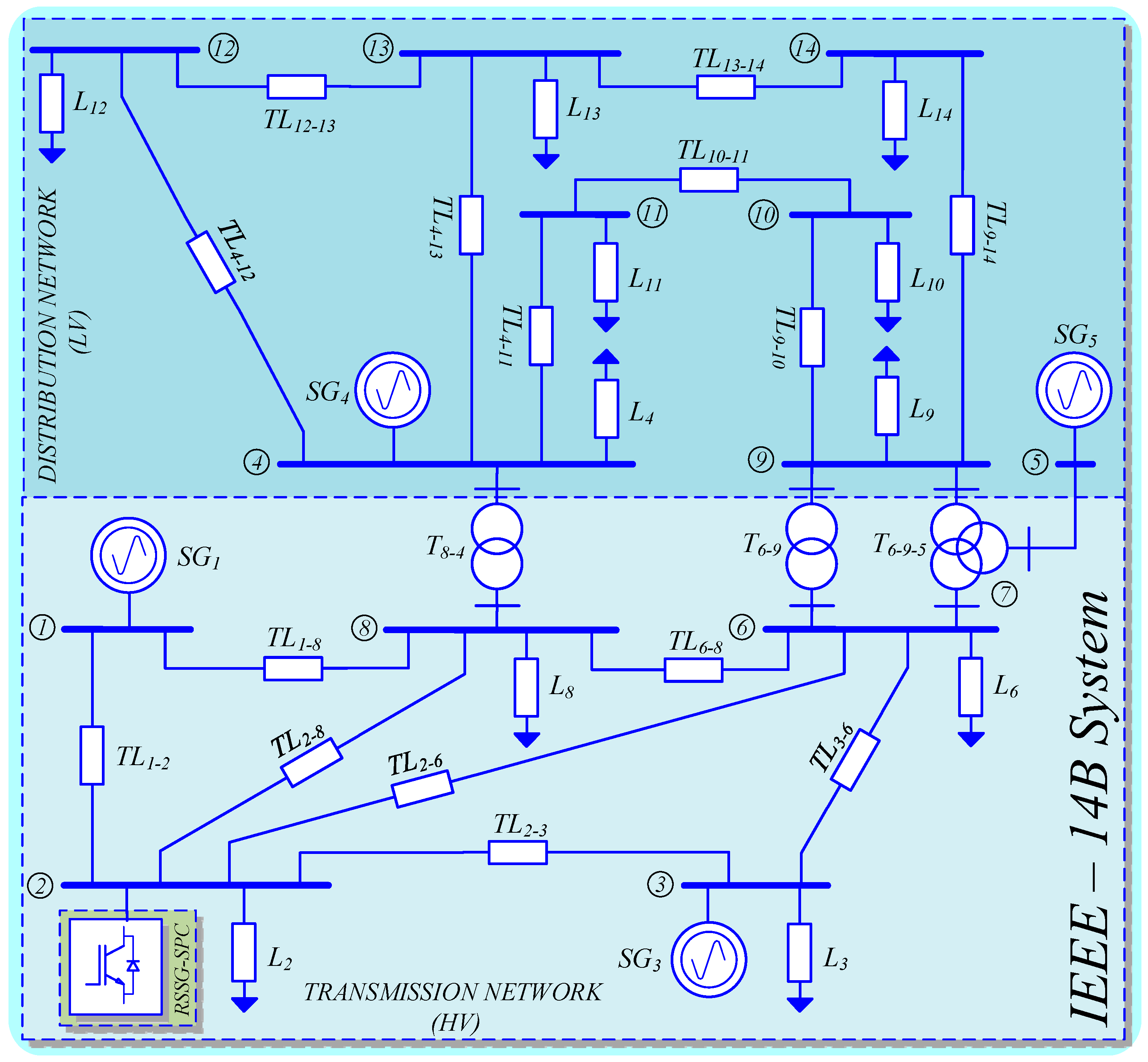
The utilized IEEE-14B benchmark is shown in
Figure 12. This benchmark contains classic generation units as well as compacted loads in two different voltage levels including high voltage transmission network 400 kV and medium voltage distribution network 66 kV. The analysis will cover both transmission and distribution levels of the power grid. In this benchmark, there are five classic generation units where only two of them generate the active power (
,
). Other generation units operate as reactive compensators to support the voltage profile [
30]. The first generation unit (
) provides
and it acts as slack bus for the grid. Moroever, the second genration unit (
) produces
. Therefore, from the dynamics of active power as well as control of phase stability point of view, those two buses are key points in the grid.
The condition for the base system while the second classic generation unit (
) is still connected on the bus (2), has been reported in
Table 1 and
Figure 13. To realize the effect of RSSG-SPC, it is assumed that all classic damping providers such as power system stabilizers has been removed from all classic generation units. In this case, all oscillatory modes of the base system will appear in analysis of the base system clearly. Based on the dynamic analysis presented in
Section 4, each generation unit has been modeled using second-order swing equation (see Equation (24)), so that five pairs of the electromechanical modes (
) are available, where four pairs of them (
) are oscillatory around the mode of generation unit of slack bus (
).
Figure 13 presents the participation of generation units in each mode (
) and
Table 1 reports the numerical details of all dynamic modes.
It can be observed in
Figure 13 that the generation unit installed in second bus (
,
), has a big factor in
, also it has a smaller share in
. Moreover, it has a moderate effect in the common mode
compared to other generation units. On the other side,
has high factor from bus (2) (
,
) and a smaller impact from the bus (3) (
,
), as well as it has an intermediate effect from the slack bus (1) (
,
). Therefore,
is the local mode of generation unit in bus (2) as well as there are a few dynamic interactions between bus (2) with generation units in bus (1) and bus (3).
The generation units installed in distribution level (
,
) also have some interactions with each other where the interaction effects are observed in
and
. Moreover,
acting as the biggest generation unit has shares in all modes but with different levels. This global sharing in all modes confirms the synchronization of all other generation units with this slack bus (
).
Table 1 shows the numerical details of the dynamic modes and the main relationship of the dynamic modes to the generation units.
As presented in
Table 1, the range of oscillation frequency in dynamic modes is
which means that these modes are the local modes of power grid at each busbar [
33]. Moreover, as mentioned earlier, it was assumed that all power system stabilizers have been deactivated. For the implementation of this deactivation, the damping coefficients of all generation units have been tuned on zero (
). Therefore, the damping ratio of all oscillatory modes (
) was equal to zero (
).
To investigate RSSG-SPC’s effects in the grid, the second classic generation unit (
) has been replaced by RSSG-SPC. It is assumed that the level of power generation, electrical parameters, and inertia of RSSG-SPC have been kept similar to
. For the simplest case, a deep analysis on the coefficient damping tuning in RSSG-SPC (
) has been done using dynamic analysis discussed in
Section 4. The results of damping tuning are illustrated in
Figure 14 and
Figure 15, and reported in
Table 2.
Figure 14 explains the effect of increasing
(labeled as
DSSG in
Figure 14) in the grid modes as well as it clarifies the critical border of the virtual damping for tuning the RSSG-SPC. As expected from participation factors matrix (see
Figure 13), only the common mode (
) and local mode of bus (2) (
) have been affected by this damping reinforcement. The neighbor dynamic modes (
) are fixed in their location because those were dynamically decoupled from bus (2) (see
Figure 13). By increasing
, the common mode (
) moved to the zones with higher stability margin. This means that the center of the inertia of the whole system tends to be in a stiffer condition. Moreover, the common mode (
) movements to a stiffer dynamic zone is a good sign for stronger electromechanical coupling between the oscillatory modes.
In
Figure 14, the pattern of the variations of
is a marginally different. This mode has been shifted to higher stability zones in a curved pattern and it arrives to a breakpoint (knee area). After the knee area it will shift to zones with lower stability margin. As shown in
Figure 14, a step increase in damping
in damping variation area
causes the knee area has shifted towards
where
. A special case occurs when
. In this case, the maximum damping with largest stability margin occurs for the mode (
), where its respective damping ratio is
. This specific tuning is the turning point for zones with smaller stability margin. Therefore, this damping tuning point is the best selection for the adjustment of RSSG-SPC from grid viewpoint. In other words, at this point, the maximum damping ratio is being transferred to mode
while operating at the highest stability margin. A more detailed discussion to obtain this optimal point has been reported in [
35].
Comparison of the dynamic analysis presented in
Figure 14 (dynamics of RSSG-SPC in grid connection) and
Figure 7 (internal dynamic of RSSG-SPC) confirms that
is the suitable adjustment while the damping ratio
occurs in the internal dynamic modes of RSSG-SPC. As mentioned in
Section 3, it was expected that this internal damping ratio would be a near-optimal tuning for the damping coefficient
in the grid connection of RSSG-SPC. In other words, Equation (5) can be a clear dynamic index to tune
in grid connection of RSSG-SPC to support the dynamic stability sufficiently.
From the frequency viewpoint in
Figure 14, the dynamic mode
achieves a decrease in the frequency of oscillations with a near square root pattern. This pattern matched with nature of RSSG-SPC modelling as well as with Equation (6). From the mechanical point of view, the frequency reduction is an indication of stiffer dynamics in the system. So, the virtual inertia sharing has been supported through RSSG-SPC in bus (2) while increasing of virtual damping
.
Table 2 and
Figure 14 confirm that damping ratio of dynamic mode
(
) has been reinforced as well as the oscillation frequency of this mode (
) has been reduced simultaneously. This is a clear indication of inertia support in the grid by RSSG-SPC. In other words, it can be concluded that the increase of the virtual damping factor in RSSG-SPC would support the effect of digital virtual inertia in the grid connection.
As discussed in
Section 3, there is a possibility to activate and control both dynamic parameters (
,
) of RSSG-SPC.
Figure 16,
Figure 17 and
Figure 18 show the controlled mode by RSSG-SPC (
) is manageable from the damping ratio and frequency viewpoints since both dynamic degrees of freedom of RSSG-SPC are accessible. In
Figure 16, the dynamic mode
can be under stable control with reasonable damping ratio level (
) for a typical range of the tuned inertia and damping.
An in-depth view of the surface
presented in
Figure 16 confirms that the observed pattern in this surface is similar to the pattern which was recognized in the internal dynamics of RSSG-SPC (see
Figure 8a). Moreover,
Figure 16 illustrates the surface slope is high for small
values but the surface approaches a flat condition for higher
which indicates stiffer dynamics in bus (2). Furthermore, for higher
values, a larger
value is required to have a specific level of damping ratio
. Furthermore, there is a similarity in the pattern for the full range of
, which is indicated in the along the peak level (peak areas in
Figure 16). These peak areas in
Figure 16 are equivalent to the knee area in
Figure 14. Therefore, we can conclude the analysis which was performed for one-degree of dynamic flexibility in RSSG-SPC (i.e., only tunable
) can be expanded two-degrees of dynamic flexibility in RSSG-SPC (i.e., tunable
and
).
Comparison between the internal damping ratio
of RSSG-SPC (see
Figure 8a) and the dynamic surface of damping ratio
in grid application of RSSG-SPC (see
Figure 16) confirms that there is a high similarity between these two surfaces and validates that dynamic mode
is under dynamic control of RSSG-SPC before reaching the peak areas. Therefore, the dynamic characteristics of RSSG-SPC has been expanded through the grid over this controlled dynamic mode. The only difference is that, after the turning points (see knee point in
Figure 14), the RSSG-SPC crossed
and it is internally close to the fully damped condition (see
Figure 8a), thereafter the dynamic mode
is not under complete control of RSSG-SPC. For this reason, after the peak areas in
Figure 16, the frequency oscillation
and damping ratio
are not under control of RSSG-SPC which indicates the worst condition tuning. In other words, after peak areas where RSSG-SPC has not a sufficient dynamic interaction with the external power grid (due to the very stiff internal RSSG-SPC dynamics), the other generation units with less damping effects (due to the deactivation of power system stabilizers) would participate more in the dynamic mode
. Therefore, the condition of this dynamic mode goes to the areas with less damping ratio and less stable margins.
The oscillation frequency of controlled dynamic modes (
) are illustrated in
Figure 17 and
Figure 18. These figures present the dynamic surface of frequencies (
) for two-degrees of dynamic freedom in RSSG-SPC. Both surfaces confirm that increasing
and
would reduce the oscillation frequency. This is shown in
Figure 16 and
Figure 17 where the frequency has been changed from 29 rad/s with minor tuning of (
,
) to less than 10 rad/s for large adjustments of (
,
). Although the frequency variation pattern does not vary much when
is increased. However, the global frequency pattern matches the damping ratio
shape. The clear difference between
Figure 16 (RSSG-SPC grid conenction dynamic performance) and
Figure 8 (isolated dynamic operation of RSSG-SPC) from the frequency viewpoint is that
has not approached zero especially for high
areas. The reason is due to the share of other classic generation units in the dynamic mode
which happens after peak areas since RSSG-SPC is internally close to fully damped situation if the dynamic tuning has been selected after peak areas.
Two dimensions dynamic design of RSSG-SPC using dynamic surfaces such as those discussed in
Figure 16,
Figure 17 and
Figure 18 would help grid operators to define an adequate operating point (optimal
,
) in the grid connection of RSSG-SPC. This optimal adjustment can be targeted to satisfy the grid operators goal to achieve a specific damping ratio and frequency in controlled dynamic mode
. Moreover, this dynamic design can be subjected to hold a reliable operating point for RSSG-SPC from the internal point of view which results in
having a plentiful stability margin. A reliable RSSG-SPC operating point indicates that an internal operating point should be selected so that if a dynamic change occurs in the external grid, the RSSG-SPC would be able to recover and control itself. From the application viewpoint, it is logical that the operating point in the areas with smooth sloop in the frequency surfaces as well as acceptable level in the damping ratio shapes must be selected. As an example, the selected dynamic tuning for grid connection of RSSG-SPC in
Figure 12 has been mentioned in
Figure 16,
Figure 17 and
Figure 18.
6. Detailed Time Domain Modelling
The goal of this section is to evaluate the trustworthiness of the forementioned methods for dynamic design and electromechanical design of RSSG-SPC. The case study of
Figure 12 has been modeled in time domain using MATLAB/Simulink. In a similar way to the modal analysis section, the grid was considered for two cases, (i) base case of the grid where all generation units are classic and are mentioned in plots by
, and (ii) the grid in the presence of RSSG-SPC where
has been replaced by RSSG-SPC and results of this case are labeled as
.
Both cases have been tested for an active load outage scenario in second bus
as depicted in
Figure 19 (active load labeled as
PLB2 and reactive load labeled as
QLB2). To have a stable and flat primary condition in measured signals, a small damping coefficient
has been considered for all classic generation units for both grid cases. Moreover, all generation units for both cases (including RSSG-SPC) are equipped with a 5% power frequency droop system. Based on the analysis discussed in
Section 5, the RSSG-SPC has been tuned in (
,
) on 100 MVA common base power which is used for dynamic analysis section. To have a clear dynamic view of the system from local (i.e., each bus) and global perspective (i.e., the whole grid), the time domain results have been evaluated from active power and frequency viewpoints in both grid cases. The time domain results are shown in
Figure 20,
Figure 21,
Figure 22,
Figure 23,
Figure 24,
Figure 25,
Figure 26,
Figure 27 and
Figure 28.
Active powers of generation units located in high voltage level are presented in
Figure 20,
Figure 21,
Figure 22,
Figure 23 and
Figure 24 for base grid (signals labeled as
in plots) and grid in presence of RSSG-SPC (signals labeled as
in plots). These figures illustrate that in the base case (dashed line plots in
Figure 20,
Figure 21,
Figure 22,
Figure 23 and
Figure 24), there are low-frequency oscillations (
) in all powers that remain in the system for a long period of time.
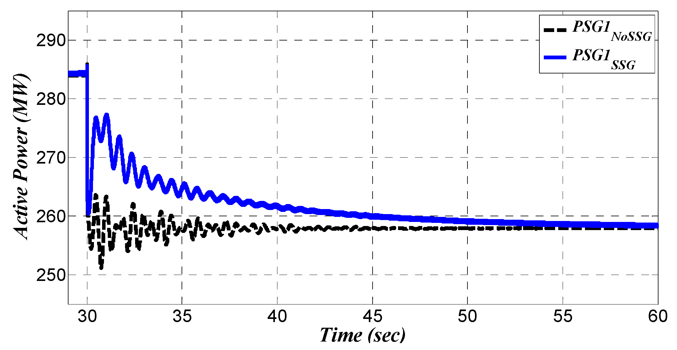
Figure 20 shows the active power of
(labeled as
PSG1) for both grid cases. The base case shows that some oscillations have appeared in the active power (see signal labeled as
). Theses oscillations are the interline oscillations between
and
. Such interline oscillations are the result of the participation of (
,
) in the dynamic mode
(belonging to bus (2)). This dynamic relationship has been discussed in the previous section and depicted in
Figure 13.
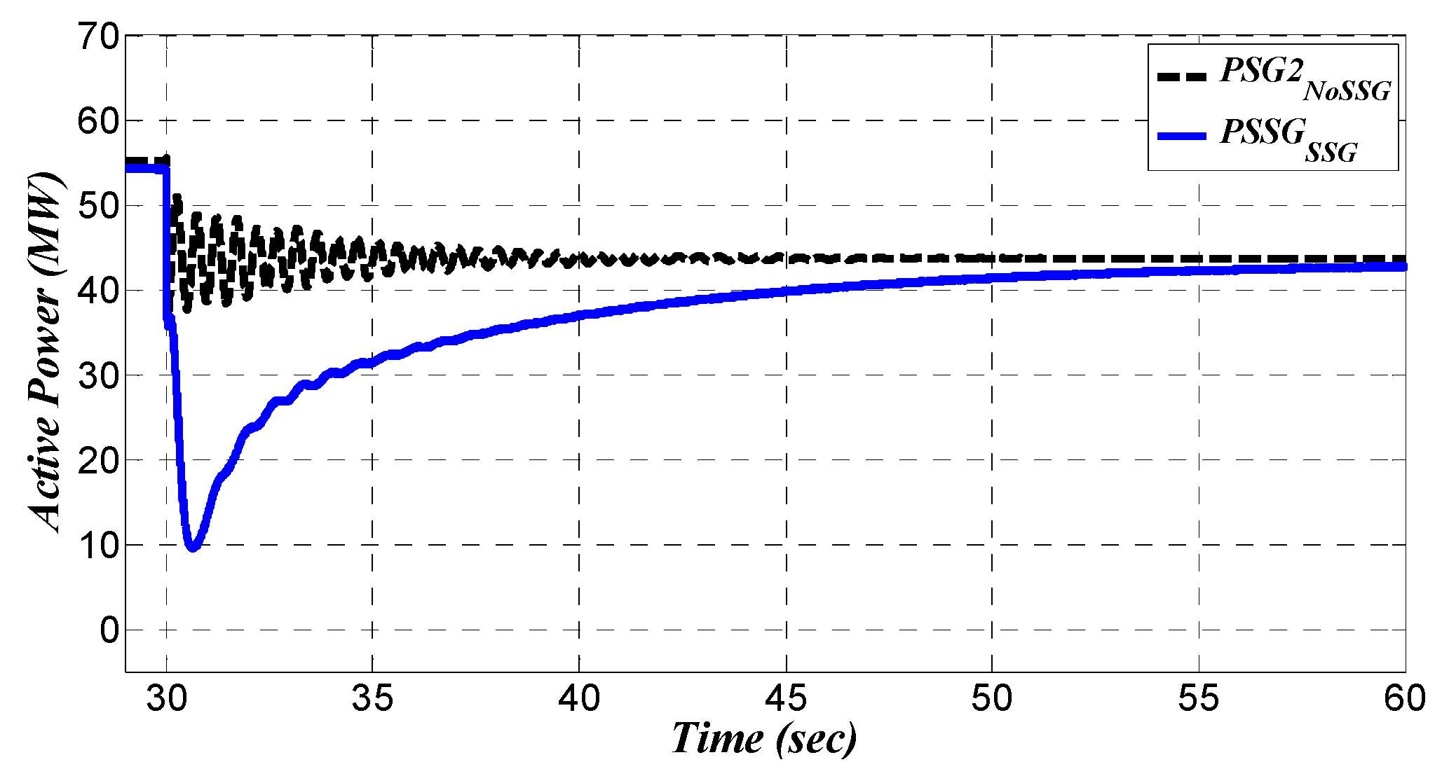
The active power of generation unit located in bus (2) is illustrated in
Figure 21 and zoomed in
Figure 22. In
Figure 22, there is oscillations in the active power of
in the base grid (signal labeled as
). This active power oscillations have a frequency around 2Hz. According to
Figure 13, the second generator (
,
) is another participator in dynamic mode
of base grid. The share of (
,
) in
is bigger than the share of (
,
) in this dynamic mode as shown in
Figure 13. Therefore, as shown in
Figure 13, the frequency oscillations of
is almost 2.1286 Hz. Therefore, this plot confirms that
is the key participator in the dynamic mode
.
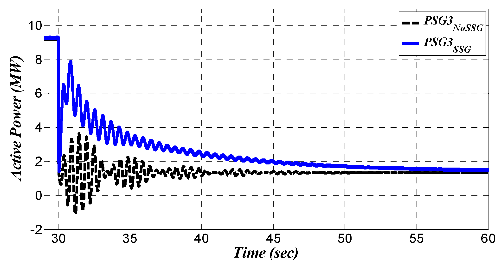
Figure 23 shows the active power of
(labeled as
PSG3) for both grid cases. These signals have been zoomed in
Figure 24 to have clear view on the early oscillations during the load step change. The base case reveals that there are two observed harmonics in the active power oscillations (signal labeled as
in
Figure 24). One of these harmonics is the interline oscillations between
and
. These interline oscillations is due to the participation of
(
,
) in the dynamic mode
(which mostly appears in bus (3)). This dynamic relationship has been depicted earlier in
Figure 13. Reviewing
Figure 13, the dynamic mode
has two main contributors including
(
,
) and
(
,
), where the share of
is larger than the share of
. Other harmonics in active power of
belongs to dynamic inertation between
and
. This interaction is also reasonable due the small contribution of
(
,
) in the dynamic mode
(see
Figure 13). Therefore, in the base grid,
has interactions with both
and
which is clearly visible in
Figure 23 and
Figure 24.
A small value of
has been tuned in all classic generation units, so that after the change in
, active powers of all main generation units are shifted to a new operating point immediately, as shown in
Figure 20,
Figure 21,
Figure 22,
Figure 23 and
Figure 24. Additionally, the low damping level appears very clearly in all active powers. This sudden shift confirms the weak dynamic condition of the base system. As discussed in the dynamic analysis section (see
Section 3), the level of the tuning of damping in the structure of synchronous machine has a significant effect on the level of inertia sharing (even on fixed inertia settings) by the synchronous machine on the grid application. As a result of this weak dynamic and very fast power shift, the effect of the power-frequency droop system (which reacts with a short time delay) did not appear in the results of the base system.
Reviewing again the active power signals (see
Figure 20,
Figure 21,
Figure 22,
Figure 23 and
Figure 24) and focusing on the grid in the presence of RSSG-SPC (signals labeled as
in plots), the results confirm that the modal analysis outcomes (see
Section 5) are valid in the presence of RSSG-SPC. This is indicated in the oscillations in bus (2) which were totally damped due to the contribution of RSSG-SPC (see signal labeled as
in
Figure 21 and
Figure 22). Furthermore, the dynamic tension between bus (3) and bus (4) as well as between bus (3) and bus (1) were cleared out (see signal labeled as
in
Figure 23 and
Figure 24). However, the oscillations with
still remains in
which is the effect of local mode in bus (3). It was not expected that RSSG-SPC (installed in bus (2)) has an effect on this specific oscillation (
) due to the very small sharing capability of bus (2) in this dynamic mode (see the share of (
,
) in
in
Figure 13).
On the other side of the network with the presence of RSSG-SPC, the dynamic tension between bus (1) and bus (2) has been reduced (see signal labeled as
in
Figure 20). According to participation of all generation units in dynamic mode
as well as moderate effect of bus (2) in dynamic mode
(see
Figure 13), the interline tensions between
and RSSG-SPC are limited within good factor although those tensions were not completely eliminated. Therefore, some early oscillations appeared in signal
in
Figure 20.
Another positive effect of RSSG-SPC is that there is no sudden shift in active powers after applying the load scenario. The contribution of the RSSG-SPC are evident during transient condition of active power, as well as the significant level of damping to the grid over the controlled dynamic mode (
) until the active power was shared between the generation units while maintaining stiffer dynamics. In
Figure 21 and
Figure 22, it can be observed that the large tuning value of
caused the RSSG-SPC to have the largest response to disturbances at the first moments after switching time. This response (
) has sufficient damping and oriented dynamics (see signal labeled as
in mentioned figures).
The RSSG-SPC reaction has a high level of damping, so it suppresses most oscillations of the active powers in the early stage as shown in
Figure 20,
Figure 21,
Figure 22,
Figure 23 and
Figure 24. Another effect of RSSG-SPC fast response is the stiffer dynamics and the increased time to share the required new production between the generation units based on the operation of power-frequency droop system. Collection of these effects leads to a smooth movement process from the primary operating point to the new steady state in all generated active powers. Therefore, from the active power viewpoint, the RSSG-SPC is acting as a fast and strong active power damper and it can have a significant effect even through low sharing power production. Considering the summation of all generated active powers (
), the temporary contribution of RSSG-SPC as a power damper (
) is almost 6.8% (
).
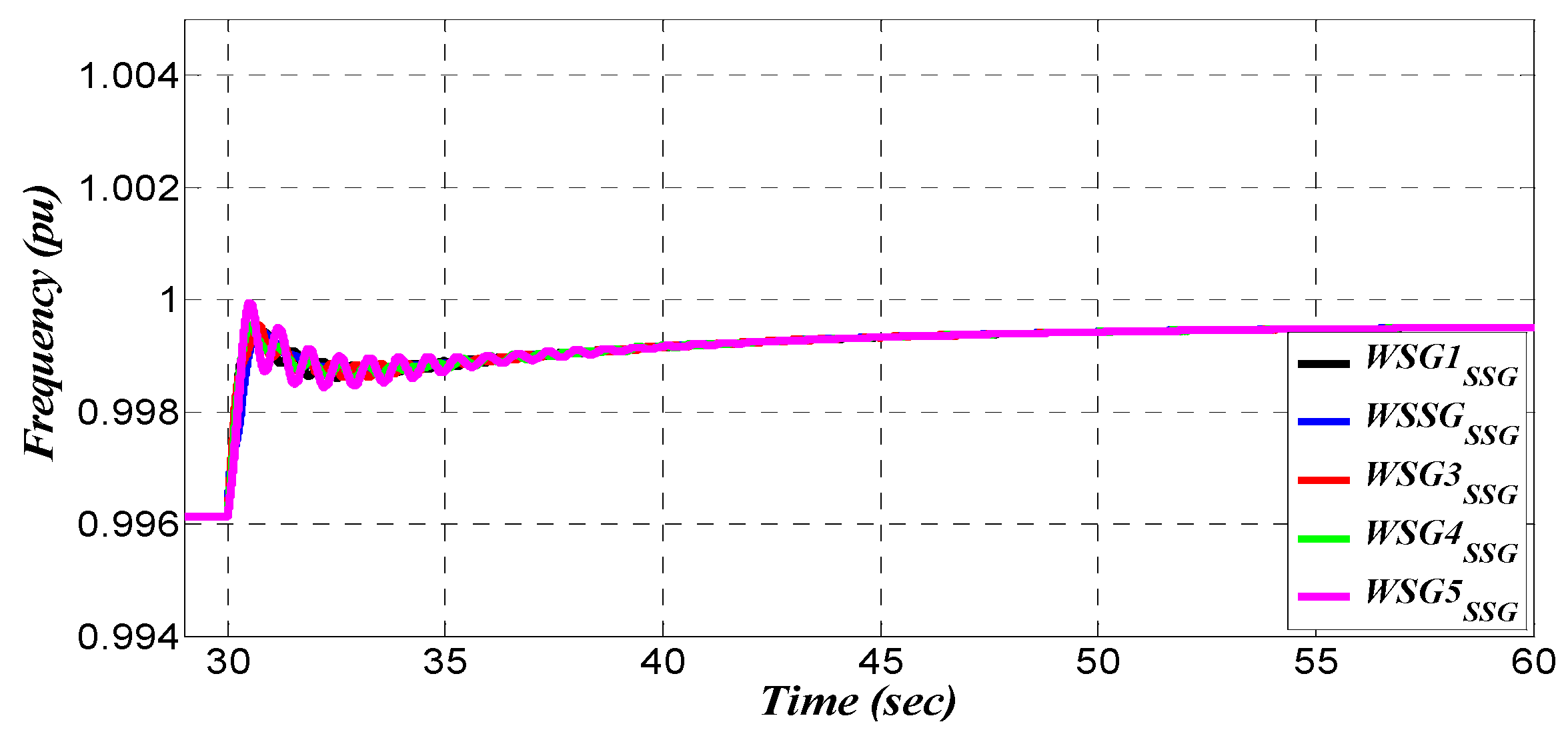
Figure 25,
Figure 26,
Figure 27 and
Figure 28 show the difference in the frequency dynamic characteristic of the grid. These figures indicate that a significant enhancement has been achieved in the frequency dynamics as well as an improvement in the generation unit synchronism on transmission level.
Figure 25 and
Figure 26 show that the generation units are oscillating around a weak center of inertia (labeled as
COI in plots) in the base grid. Those generation units achieve a large peak in the frequency variations (
) in response to a (
) load change. Moreover, the damping ratio of this center of inertia is insignificant, therefore the center of inertia would be settled on the new steady state condition after some oscillations (see
Figure 25). Furthermore, as shown in
Figure 26, there is a primary high frequency variation (
), as well as the rate of change of frequency (labeled as
ROCOF in plots) of each unit is huge. This is due to the low damping coefficient tuned in generation units (
) which prevents inertia sharing in the base grid.
The stiffness in dynamics as well as damping of the frequency oscillations in the presence of RSSG-SPC are clearly visible in
Figure 27 and
Figure 28. In this case, the dynamics of the center of inertia is stiffer and there is no significant peak in frequency variations after switching time (
). Moreover, there is no global oscillations in center of inertia which was significantly damped.
In the zoom view of
Figure 27 which is shown in
Figure 28, it can be observed that there is a rigid flat shape of center of inertia as well as lower rate of change of frequency in each generation unit. Deeper analysis on
Figure 28 confirms that the dynamics of RSSG-SPC frequency (labeled as
in plots) is very close to the dynamics of the center of inertia. This means that RSSG-SPC is the main factor to support the center of inertia. In other words, in presence of RSSG-SPC, the center of inertia is majorly under control of RSSG-SPC as compared to the other generation units. Moreover,
Figure 28 shows that even the biggest generation unit (
) has more frequency oscillations around the center of inertia (see signal labeled as
in
Figure 28), compared to RSSG-SPC’s frequency oscillations (see signal labeled as
in
Figure 28).
From the illustrated Simulink results it can be concluded that:
- (i)
The results of dynamic analysis have been validated and the proposed method gives a trustable design of RSSG-SPC.
- (ii)
A well-designed RSSG-SPC based on the suggested method can damp the electromechanical oscillations in active power and frequency which results in a significant improvement in the support to the dynamics of external power grid.
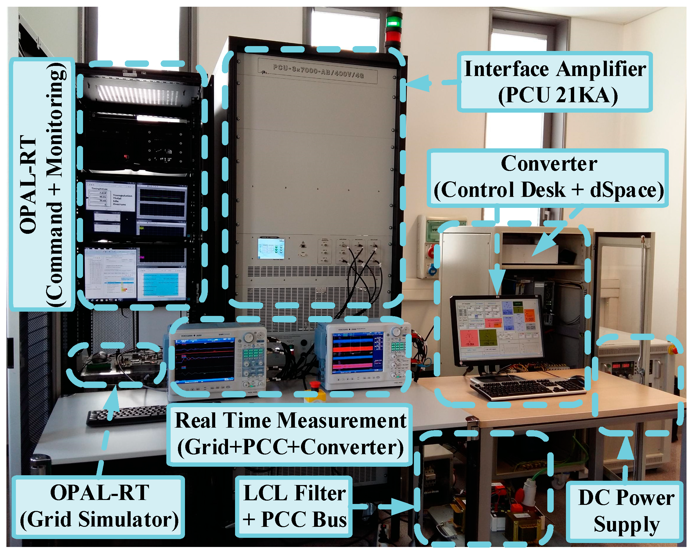
7. Real Time Laboratory Test
For experimental validation of the aforementioned analysis, a high-power laboratory platform shown in
Figure 29 has been developed to test the system. The case study data is reported in
Table 3. The main goal of this section is to validate the dynamic analysis results as well as to evaluate time domain outcomes of simulation section.
Figure 29 illustrates that this platform consists of an OPAL-RT as the core of real-time test where a developed model of IEEE-14B benchmark has been implemented. On the other side, a 5 kV, 10 kHz voltage source converter emulates RSSG-SPC characteristics. The converter has been controlled by SPC technique and several auxiliary control layers for further adaption with the grid connection situations such as power-frequency droop system. A high power PCU 21 kVA/400 V amplifier acts as the interface for emulation of dynamic interaction between RSSG-SPC and external power grid which has been emulated in OPAL-RT.
The implementation technique used for creating the hardware-in-loop test using this platform is shown in
Figure 30. After emulating the external power grid in OPAL-RT, the voltage signal of PCC (
) is sent to PCU as a command signal. Thus, the PCU emulates power grid performance at PCC, while power amplifier terminals are connected to the RSSG-SPC power converter filter.
The measured current signals (
) in PCC is the feedback signal to OPAL-RT using proper step-down gains. Therefore, the RSSG-SPC operates as a current source in OPAL-RT and controlled by the feedback current signal while the corresponding bus voltage is emulated in the bus
. Using this closed current loop, all dynamic-electrical interaction between amplifier PCU (as PCC emulator) and power converter (as RSSG-SPC emulator) has been inserted to the external power grid model and results can be analyzed in a real situation. The power grid model in OPAL-RT has been tested for the load scenario shown in the previous Simulink analysis and the real-time signals were captured and presented in
Figure 31,
Figure 32,
Figure 33,
Figure 34,
Figure 35,
Figure 36 and
Figure 37.
The following signals have been captured for each case of external power grid (
,
) including: (i) the frequency deviations of all generation units around the center of inertia (
). These signals clarify the frequency distortions of each generation unit with high details, (ii) the consumed active and reactive power of the load (
and
) where the operation scenario has been applied, and (iii) active power of the generation units (
and
). The
Figure 31 and
Figure 32 show the global view of captured real-time signals and confirm that all aforementioned discussions in the theoretical part, as well as Simulink outcomes have been validated for both cases of power grid (
,
). The frequency and power signals are zoomed in
Figure 33,
Figure 34,
Figure 35 and
Figure 36 for in depth evolution of the results.
The frequency deviation signals are zoomed in
Figure 33 and
Figure 34 to acquire a clearer view of the results. As illustrated in these figures, the frequency coupling of the generation units has been supported in the presence of RSSG-SPC. Since the deviations around the center of inertia have been presented in this work, the frequency jumps at switching time has been ignored in these scope captures due to the tracking capability of frequency signals in dc coupling modes of the oscilloscope. Using this technique, the details of frequency variations around the center of inertia were made clearly visible. As mentioned before, the stronger frequency coupling is a good indication of the stronger dynamics in the whole power grid which has been achieved in presence of RSSG-SPC.
The oscillations in generated active powers are compared in
Figure 35 and
Figure 36. These figures show that the damping ratio level of
in the active power of RSSG-SPC has been approved in this test (see signal labeled
in
Figure 36). Moreover, the interaction of RSSG-SPC with
has been limited significantly. Moreover, these signals approve the RSSG-SPC role as strong active power damper in grid connection to remove the electromechanical oscillations from active powers.
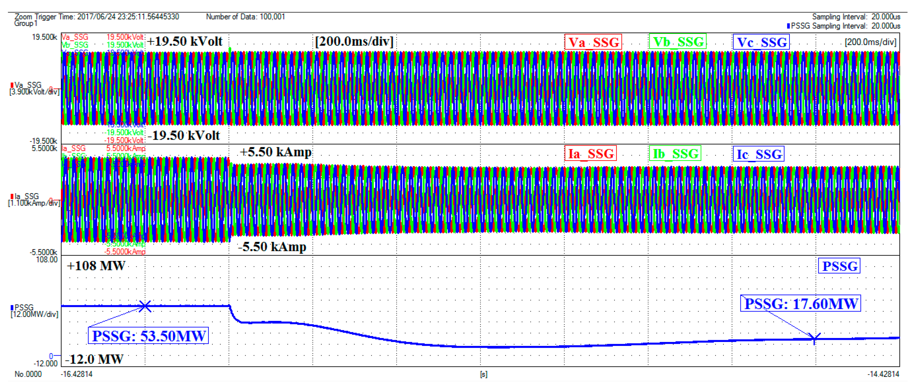
Figure 37 shows three-phase voltages (
Vabc_SSG) and three-phase currents (
Iabc_SSG) of PCC. Moreover, it shows the active power absorbed by power converter from the amplifier PCU at switching time which is emulated in the OPAL-RT model. Furthermore,
Figure 37 reveals that a well-designed RSSG-SPC based on the proposed method can control the power transients in the grid connection while RSSG-SPC maintains a stiff and smooth dynamics. Although, the load scenario has been applied without any rate of change and it has been considered as pure step (considering worst case scenario), there are no critical tensions in the voltages and currents in the presence of RSSG-SPC (see
Figure 37).
Therefore, an RSSG-SPC which has controllable electromechanical part which is adaptable with the external power grid situations would be able to support dynamic stability indices of the active power and frequency. The RSSG-SPC provides this dynamic support by relying on its fast reaction to the grid disturbances, as well as control of the transients of power-sharing while it acts as a strong active power damper. Furthermore, RSSG-SPC supports dynamic stability by providing the stronger dynamic coupling between other generation units and itself. The RSSG-SPC can achieve this grid supporting service even with a small percentage of power sharing and temporary production in the grid as it has been confirmed in this real-time test. Further discussions and test results have been presented in [
30].


 ,
, 


