Article

Investigation: Cutting Transport Mechanism in Inclined Well Section under Pulsed Drilling Fluid Action

1
School of Mechanical Engineering, Southwest Petroleum University, Chengdu 610500, China
2
School of Engineering, Southwest Petroleum University, Nanchong 637000, China
*
Author to whom correspondence should be addressed.
Energies 2021, 14(8), 2141; https://doi.org/10.3390/en14082141
Submission received: 14 March 2021 / Revised: 7 April 2021 / Accepted: 8 April 2021 / Published: 11 April 2021
(This article belongs to the Section I: Energy Fundamentals and Conversion)

Abstract

:
Due to gravity, drilling cuttings are easily accumulated in an inclined well section, ultimately forming a cuttings bed, which places the drill pipe under strong friction torque. In severe cases, this can cause dragging, stuck drills, and broken drill tools. Because conventional drilling fluids are difficult to prevent the formation of cuttings in inclined well sections, a method of carrying cuttings with the pulsed drilling fluid to improve wellbore cleanness is proposed. Experiments and numerical simulations are conducted to investigate the effects of cuttings bed transport velocity, cuttings size, cuttings height, drill pipe rotation speed, cuttings bed mass, and roughness height. The optimal pulse parameters are determined per their respective impact on cuttings transport concerning varied periods, amplitudes, and duty cycles of the pulsed drilling fluid. Compared to cuttings transport under the conventional drilling fluid flow rate, the pulsed drilling fluid produces the turbulent dissipation rate, increases cuttings transport velocity, and thus improves the wellbore clearance rate.

1. Introduction

The transport of cuttings in an inclined well section with a small borewell is a major challenge in drilling applications. The cuttings bed formed in the drilling process can cause stuck drills and increased torque [1]. Cuttings settle to form cuttings beds at low drilling fluid flow rates and create wellbore shaft instability [2,3]. It is necessary to enhance cuttings transport efficiency while keeping the flow rate within an acceptable range.
Previous research on cuttings transport in inclined wells mainly centers on experiments and numerical simulations. Larsen et al. (1997) [4], for example, measured the impact of various mud properties, cuttings size, rates of penetration (ROPs), and hole deviation angle on critical flow rate experimentally to establish an empirical critical flow rate formula. Duan et al. (2008) [5] regressed an empirical formula of cuttings bed height based on experimental results. Shadizadeh and Zoveidavianpoor (2012) [6] and GhasemiKafrudi and Hashemabadi (2016) [7] found that a high-viscosity fluid carries cuttings more effectively than a low-viscosity fluid. Yu et al. (2007) [8] found that the height of the cuttings bed sharply increases upon a certain drill pipe eccentricity; the torque also increases at this point, resulting in an increased likelihood that the drill will stick.
There have been many other valuable contributions to the literature. Ozbayoglu et al. (2008) [9], Sorgun et al. (2011) [10], and Ofei and Yaaqob (2019) [11] investigated annulus cuttings distribution patterns created by a rotating drill pipe. Certain types of drill pipe rotation appear to enhance the transport efficiency of the cuttings, especially when the drill pipe is in a completely eccentric position. This can minimize cuttings bed thickness under low-viscosity and high-viscosity fluid conditions. Piroozian et al. (2012) [12] found that increasing the drilling fluid flow rate can significantly enhance the recovery of cuttings. Kim et al. (2014) [13] measured friction coefficient, pressure loss, particle transport rate, and particle volume fraction parameters in a series of experiments to observe their effects on annulus cuttings density, drill pipe rotation, drilling fluid flow rate, and hole deviation angle.
Other researchers use a three-layer model [14,15,16,17] to describe annulus cuttings distribution patterns comprehensively and with minimal error regarding the process of cuttings deposition and diffusion. Han et al. (2010) [18] used the Euler method to study the upward movement of solid particles in a solid–liquid mixture in a vertical and inclined rotating inner cylinder. This method allows solid pressure and viscosity to be determined with commercial software rather than empirically. Ofei et al. (2014) [19] used the computational fluid dynamics (CFD) method to analyze the effects of various fluid velocities and inner/outer pipe diameter ratios on solid–liquid flow pressure loss and cuttings density. Their results indicated that reliable CFD simulations accurately reflect complex, real-world oil and gas drilling operations.
Several parameters affect cuttings transport. Sun et al. (2014) [20] and Akhshik et al. (2015) [21] used CFD to explore the effects of drill pipe rotation on the cuttings transport in complex structures. They concluded that drill pipe rotation significantly affects the distribution of cuttings in inclined sections. At low drilling fluid flow rates, a certain drill pipe rotation can significantly reduce cuttings density; at high drilling fluid flow rates, the impact of drill pipe rotation on cuttings density is almost entirely negligible. Heydari et al. (2017) [22] found that drill pipe eccentricity can increase the accumulation of cuttings—the drill pipe tends to tilt downwards, narrowing the flow channels available for cuttings leading to their precipitation. Epelle and Gerogiorgis (2017) [23] later pointed out that larger-diameter cuttings can generate high-frequency eddies in certain areas, thereby increasing turbulence. Smaller cuttings tend to spread more evenly in the annulus. Ozbayoglu et al. (2010) [24] found that using a drilling fluid flow rate below a certain threshold causes cuttings to be deposited into the bed.
Indeed, drilling fluid flow rate has an important impact on cuttings transport. The annulus drilling fluid flow may be a conventional constant flow or a pulsed wave. The application of pulse drilling fluid in the drilling process can effectively improve penetration rate [25,26]. The pulsed jet generator modulates the conventional continuous flow of drilling fluid through the drill bit into a pulsed flow, forming a pulsed jet at the nozzle outlet and generating hydraulic pulses, cavitation erosion, and local negative pressure at the bottom of the well. This approach enhances the flow field at the bottom of the well, improves purification capacity, and helps break down rock material, thus enhancing ROP and improving cuttings transport efficiency [27,28,29,30]. The hydraulic-pulsed cavitating-jet generator [31] and self-oscillation pulsed percussive rotary tool [32] have successfully been applied for these purposes.
Previous research on pulse drilling fluid has mainly centered on improving rock breaking efficiency and ROP [33,34]. There has been little analysis to date on the impact of pulse drilling fluid on cuttings transport. The cuttings transport characteristics of pulsed drilling fluid in inclined wells were examined in the present study through experiments and numerical simulations. Various operation parameters were explored to observe their effects on cuttings flow patterns. Sensitivity analysis was then performed on the pulse parameters to optimize them. The results of this work may have guiding significance for the further research and development of pulsed drilling fluid cuttings conveying tools.

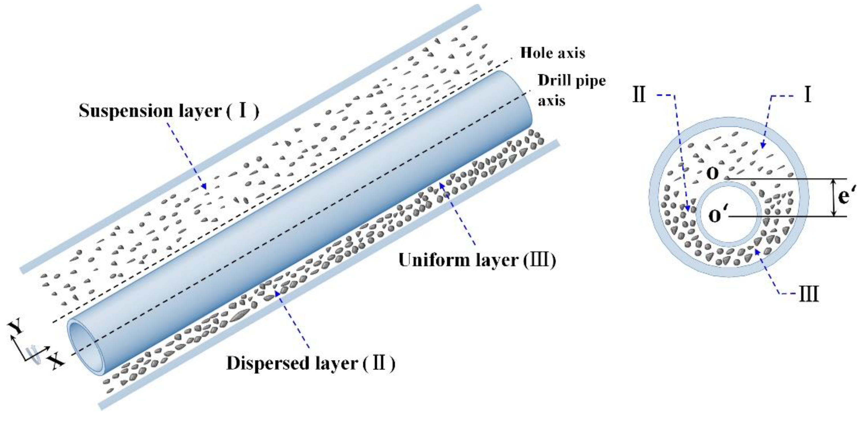
2. Model Description

An annulus in an inclined well section with a stable well wall was selected as the object of this study. The cuttings in this area are affected by gravity, buoyancy, and drag force. A portion of the cuttings settles into the bed, while the remainder moves with the flow of the drilling fluid, as shown in Figure 1.
A three-layer model was used to simulate the true state of the annulus fluid. The model is composed of a suspension layer (I), dispersed layer (II), and uniform layer (III) between, in which mass and momentum are transferred. The drilling fluid flow rate in the suspension layer is high, while the cuttings density is low. The particles on the surface of the uniform layer undergo rolling or lifting due to the scouring effect of the fluid in the suspension layer, forming a dispersed layer comprised of cuttings. The number of cuttings per unit volume in the uniform layer is stable. The three-layer model can turn into a two-layer model or a one-layer model (in the vertical section) under certain conditions [14,16]. For example, there may be no cuttings transport in the suspension layer or the uniform layer on the bottom may slide together or disappear, or the dispersed layer may disappear (in the inclined section).
During the drilling process, the transport of cuttings may be affected by many environmental factors, including the downhole area where gas and water are generated and annulus temperature [3,35,36]. However, the flow rate of the drilling fluid in the area selected for observation here is stable; cuttings transport is relatively unaffected by temperature in this case.

2.1. Theory

There are three main aspects to the interaction of drilling fluids with cuttings: the dispersion of cuttings due to turbulence of the carrier fluid, cuttings segregation due to complex unsteady motions and the modulation of the turbulence due to the presence and motion of cuttings [23,37]. Both cuttings and drilling fluid are subject to interphase forces in this model as well. The flow characteristics of drilling fluid and cuttings were observed here with an Euler two-phase flow model.
The mass conservation equation of an annulus drilling fluid [17] is:
( A ( 1 C a ) ) t + Q l x = 0 .
Drilling fluid in an annulus can be divided into three parts according to the three-layer model. Their mass conservation equations are expressed, respectively, as follows:
( A u ) t + ( V u A u ) x = 0 ,
( A m ( 1 C m ) ) t + ( A m ( 1 C m ) V m l ) x = ( E r D r ) S b m ,
( A b Φ ) t + ( A b Φ V b l ) x = ( E r D r ) S b m .
Similarly, the cuttings mass conservation equations for the dispersed and uniform layer are, respectively:
( A m C m ) t + ( A m C m ( V m V s l i p ) ) x = ( E r D r ) S b m ,
( A b ( 1 Φ ) ) t + ( A b ( 1 Φ ) V b ) x = ( E r D r ) S b m .
The momentum conservation equations of the three parts in the three-layer model are, respectively expressed as [14,16]:
( ρ l A u V u ) t + ( ρ l A u V u V u ) x = A u ( P x + ρ l g cos θ ) τ u S u τ u m M S u m ,
( ρ m A m V m ) t + ( ρ m A m V m V m ) x = A m ( P x + ρ m g cos θ ) τ m S m + τ u m S u m τ m b S m b + ρ s U s ( E r D r ) S m b ,
( ρ b A b V b ) t + ( ρ b A b V b V b ) x = A b ( P x + ρ b g cos θ ) ( τ b + τ g ) S b + τ m b S m b ρ s V s ( E r D r ) S m b .
The drilling fluid presents highly nonlinear and complex flow characteristics as it transports the cuttings out of the well. The rotation flow has high turbulence intensity, so it is well-suited to the standard model [37]:
t ( ρ l k ) + x i ( ρ l k v l ) = x j ( Γ k k x j ) + G k Y k ,
t ( ρ l ω ) + x i ( ρ l ω v l ) = x j ( Γ ω ω x j ) + G ω Y ω + D ω .
The Huilin–Gidaspow model is an appropriate fit for a two-phase flow experiment, so it was used here to calculate the drag force between solid and liquid components [22]. The Ergun equation and the Wen and Yu model constitute the Huilin–Gidaspow model [38].
The Wen and Yu model is:
K W & Y = 3 ρ s ε l ( 1 ε l ) 4 d p C D | u s u l | ε l 2.65 ,
where C D is the resistance coefficient of the cuttings particles, expressed by Equation (13):
C D = { 24 R e s ( 1 + 0.15 R e s 0.687 ) , R e s 1000 0.44 , R e s > 1000 .
The Ergun equation is:
K E = 150 μ l ( 1 ε l ) 2 ε l ( d s ϕ ) 2 + 1.75 ρ l ( | u l u s | ) ( 1 ε l ) d s ϕ ,
and the Huilin–Gidaspow model is:
K = ( 1 2 + arctan [ 262.5 ( ε s 0.2 ) ] π ) K E + ( 1 2 arctan [ 262.5 ( ε s 0.2 ) ] π ) K W & Y .

2.2. Boundary Conditions

The calculation domain of this study is a finite length eccentric annulus in the inclined well section. The well wall is stable without cracks. The drill pipe rotates at the specified speed. The annulus geometry and calculation network discussed here are shown in Figure 2. Meshing was performed with a structural hexahedral mesh. The boundary conditions are characterized by the velocity inlet; the drilling fluid and cuttings flow direction was set to be perpendicular to the inlet interface. A pressure boundary condition was imposed at the outlet. In this case, the pressure setting is the same as the environmental pressure. It was assumed throughout the simulation that the drill pipe is smooth and non-slippery.

3. Cuttings Transport Experiment of Pulsed Drilling Fluid in Inclined Well Section

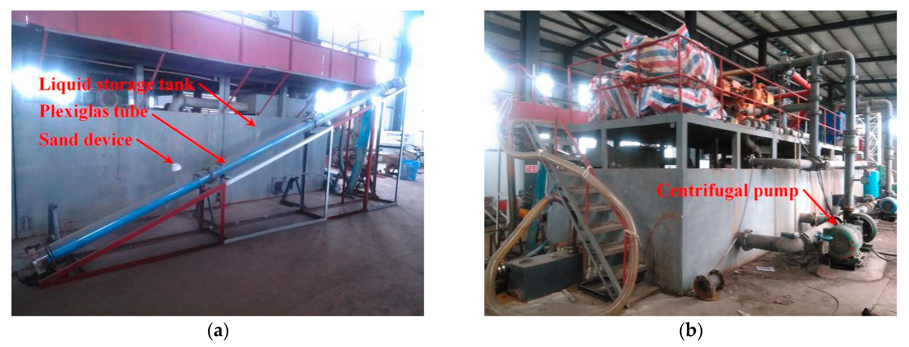
3.1. Experiment Platform

The reference drilling site was well 1702 of 13 inclined wells in Nanbao, Hebei Province. A visual test rig was established to carry out the cuttings transport experiment with actual drilling fluid. The drill pipe rotated in an inclined annulus space throughout the experiment. The equipment included a Plexiglas tube, centrifugal pump, liquid storage tank, control valve, cuttings recycling tool, filter, rotating device, and data acquisition system. The flow circuit is shown in Figure 3. The experimental setup is shown in Figure 4.
A Plexiglas tube was used as the well wall to observe the cuttings transport process and any changes in the cuttings bed. The Plexiglas tube had a total length of 6 m and a hole deviation angle of 60°, which was the least preferable angle in a wellbore cleaning process [1,39]. The transport of cuttings was observed experimentally under the various parameters listed in Table 1. The roughness height of the “rough” wall surface, in this case, was the average size of cuttings on the wall.
The cuttings transport experiment was run in a four-step process.
(1)
The control valve was manipulated to control the centrifugal pump to transport drilling fluid from the liquid storage tank to the Plexiglas tube;
(2)
Once the flow of drilling fluid was stable, cuttings were added, the inner pipeline was rotated, and the trajectory of the cuttings was recorded with a high-speed camera;
(3)
The drilling fluid carried the cuttings away from the Plexiglas tube and flowed to the cuttings recycling pool. The filter separated the cuttings and the drilling fluid returned to the liquid storage tank;
(4)
The camera video was processed and converted into frame-by-frame images. The cut-tings transport time and position were determined accordingly, recorded, and used to calculate the time, velocity, and other relevant characteristics of the cuttings transport process.

3.2. Experimental Results and Discussion

3.2.1. Cuttings Flow Patterns

The cuttings flow pattern is mainly affected by precipitation and resuspension. The movement state of cuttings is affected by certain factors, such as flow rate, characteristics of cuttings and drilling fluid, well angle, drill pipe speed, and annulus size.
The cuttings flow pattern in the inclined well section in this experiment was mainly a waved-bed flow (Figure 5). The waved-bed flow produced an unstable filled cuttings bed wherein the filled cuttings constantly moved. The cuttings slid down from the back of the cuttings bed, then moved forward along the drilling fluid flow direction before depositing again at the bottom of the annulus.

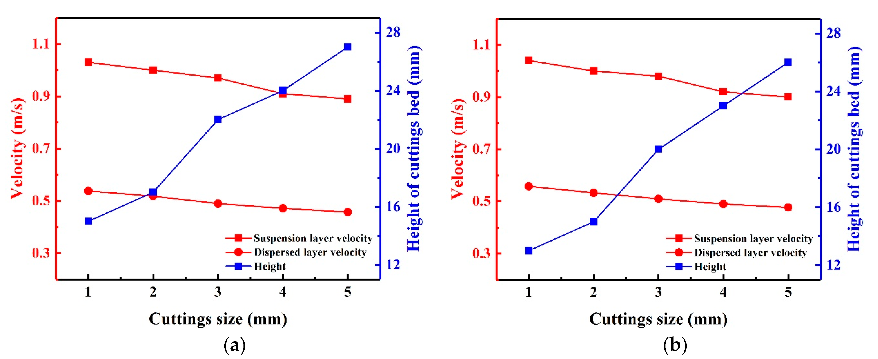
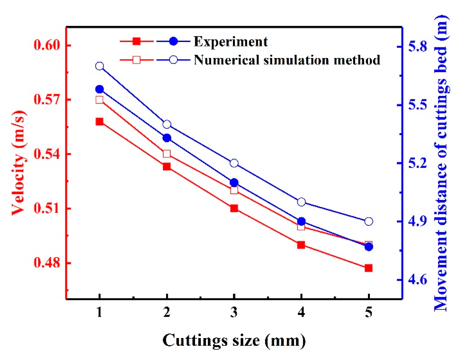
3.2.2. Impact of Various Cuttings Sizes

As shown in Figure 6, as cuttings particle size increases and drilling fluid flow state remains unchanged, the resistance overcome by the startup of the cuttings bed also increases, while some cuttings remain unchanged. At the same time, suspension cuttings and dispersed cuttings are affected by gravity and gradually settle, increasing the cuttings bed height. The cuttings bed height gradually increases as the suspension cuttings velocity and bed movement velocity decrease. When the cuttings are 3 mm in size, the pulse and conventional drilling fluid cuttings transport velocity in the uniform layer are 0.51 m/s and 0.49 m/s, respectively. At the same size of cuttings, the height of cuttings bed under the action of pulse drilling fluid is lower than that of conventional cuttings transport. Compared to conventional drilling fluid cuttings transport, the pulsed drilling fluid cuttings transport thus appear to have better transport effects. Small cuttings produce a lower bed height, allow the material to move at a greater velocity, and improve the overall efficiency of cuttings transport in this system.

3.2.3. Impact of Various Drill Pipe Rotation Speeds

The drill pipe rotation improves cuttings transport efficiency in the inclined well section. This rotation creates a tangential force, which acts on the cuttings causing them to move laterally. When the cuttings on the bed move to the high-speed annulus area, they move at a greater distance per unit time. They leave the area with the drilling fluid, reducing the density of cuttings in the annulus. This drilling tool rotation also increases the turbulence of the annulus drilling fluid, further improving the cuttings transport efficiency. The drilling tool particles also “squeeze” larger cuttings into smaller ones during the rotation process, enhancing the drilling fluid’s ability to carry them.
As shown in Figure 7, the velocity of the suspension layer and uniform layer first increase and then decrease as the drill pipe rotation speed increases. The height of the cuttings bed gradually decreases, reaching a minimum value of 14 mm at 120 rpm, and then increases at drill pipe rotation speeds beyond 120 rpm. It appears that an increase in rotation speed allows the drilling fluid to carry more particles suspended on the surface of the cuttings bed away from the bed, effectively reducing cuttings settlement. When the drill pipe rotates too fast, it changes the flow field structure and produces more turbulence, which, in turn, impedes the movement of the cuttings bed and increases the height of the cuttings bed. These observations suggest that an appropriate drill pipe rotation speed can effectively minimize cuttings bed height.

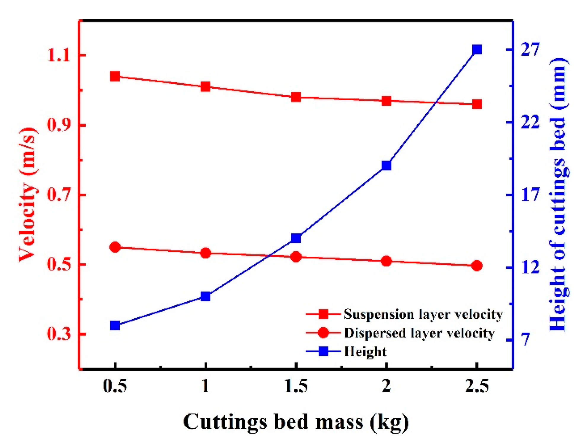
3.2.4. Impact of Different Cuttings Bed Mass

As shown in Figure 8, the uniform layer cuttings concentration increases as the cuttings bed mass increases, making it more difficult for the drilling fluid to destroy the cuttings bed. Simultaneously, the velocity of suspended cuttings decreases and some of the cuttings settle, increasing the height of the cuttings bed. Properly reducing the ROP is conducive to timely cleaning of cuttings.

3.2.5. Impact of Various Well Wall Roughness Heights

As shown in Figure 9, with the increase of roughness height, the transport velocity of the cuttings decreases. The amount of cuttings carried by drilling fluid away from the cuttings bed also decreases as roughness increases. The roughness is taken from the average diameter of the cuttings on the borehole wall surface. In short: a smooth well wall facilitates cuttings transport with pulsed drilling fluid. An increase in the wall roughness height creates excess friction between the cuttings and the well wall. The cuttings are subject to gravity and thus tend to deposit under the annulus, so it is necessary to take control measures accordingly during drilling.

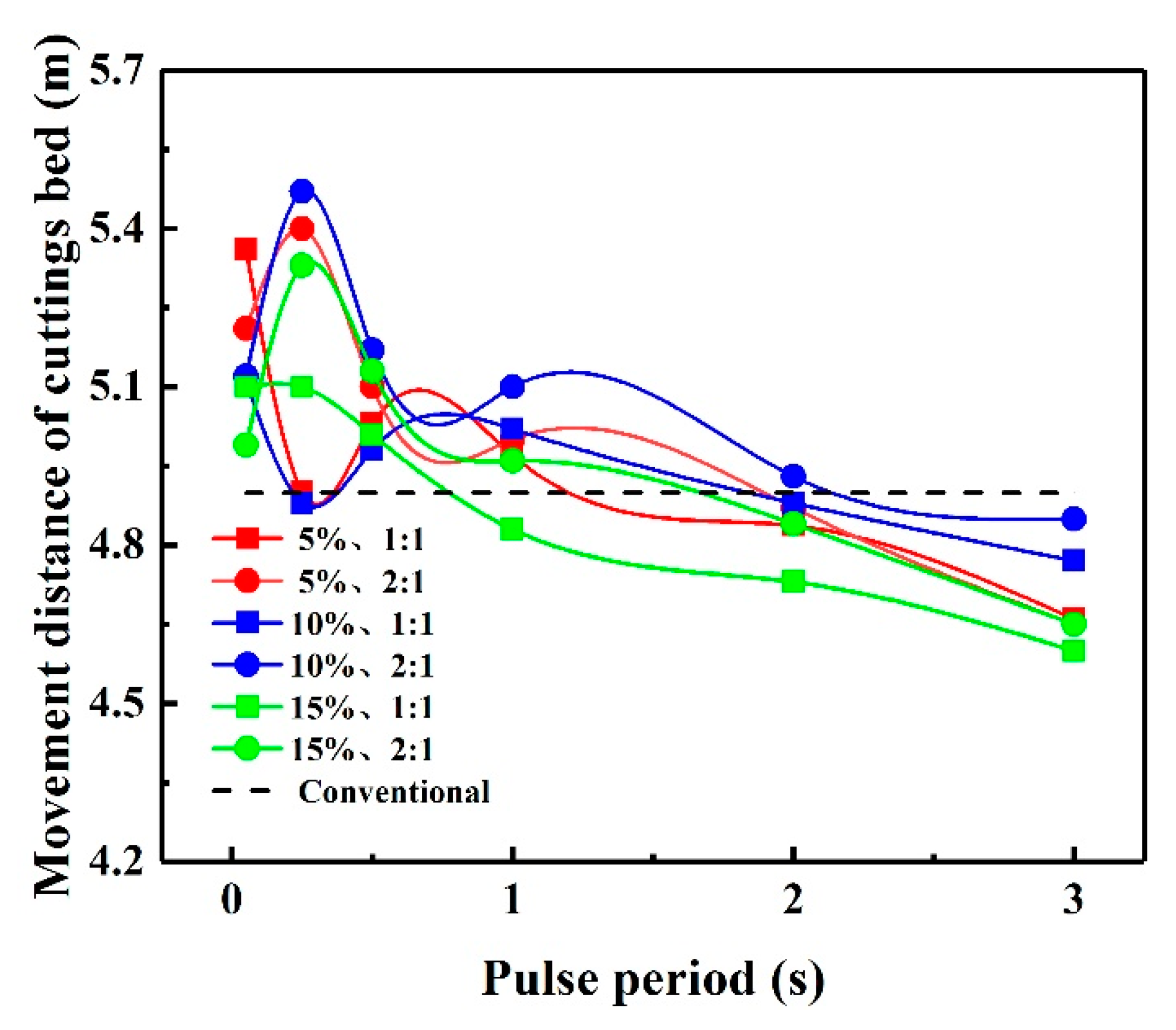
3.3. Sensitivity Analysis of Pulse Parameters

The pulse parameters set under the experimental conditions in this study are listed in Table 2 [40]. As shown in Figure 10, with the same q and pulse amplitude ratio, the cuttings bed movement distance decreases as the pulse period increases. The optimal pulse period T = 1 s, at which point the cuttings bed movement distance is 5.1 m when duty cycles q = 2:1 and pulse amplitude ratio is 10%; this distance well exceeds the distances observed under other parameters. When q = 1:1 and 15% pulse amplitude ratio are used, the cuttings bed movement distance is inferior to that of the conventional cuttings bed. In effect, appropriate pulse parameters can significantly improve the transport efficiency of the cuttings. T = 1 s, q =2:1, and 10% pulse amplitude ratio can be considered optimal parameters for this experiment.

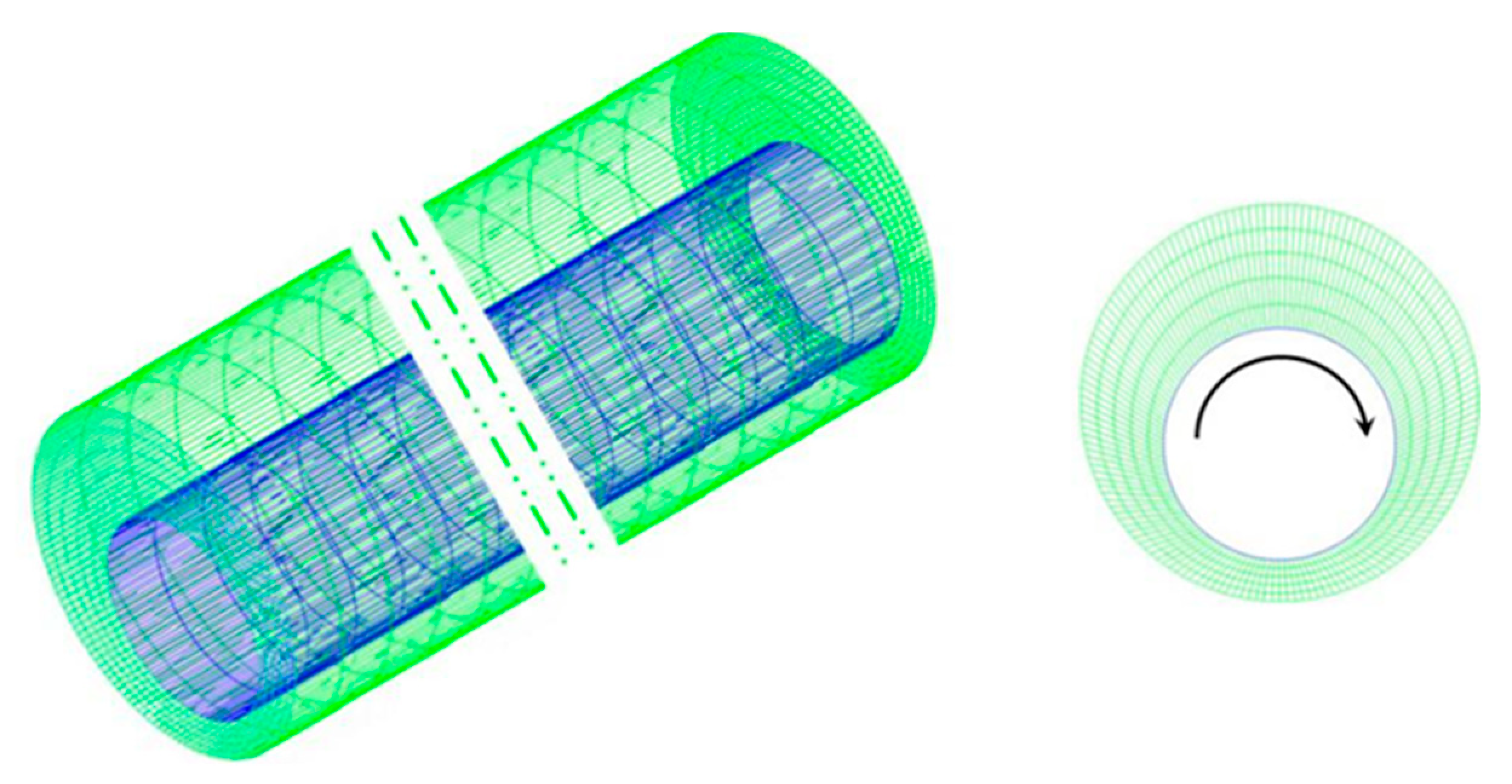
4. Numerical Simulation

4.1. Numerical Model Validation

Figure 11 shows the experimental cuttings velocity and cuttings bed movement distance information revealed by the numerical simulation. The average error is 2.03%, which satisfies the necessary conditions for engineering application. The numerical model established in this paper is suitable for studying cuttings transport in drilling fluid under pulse action.

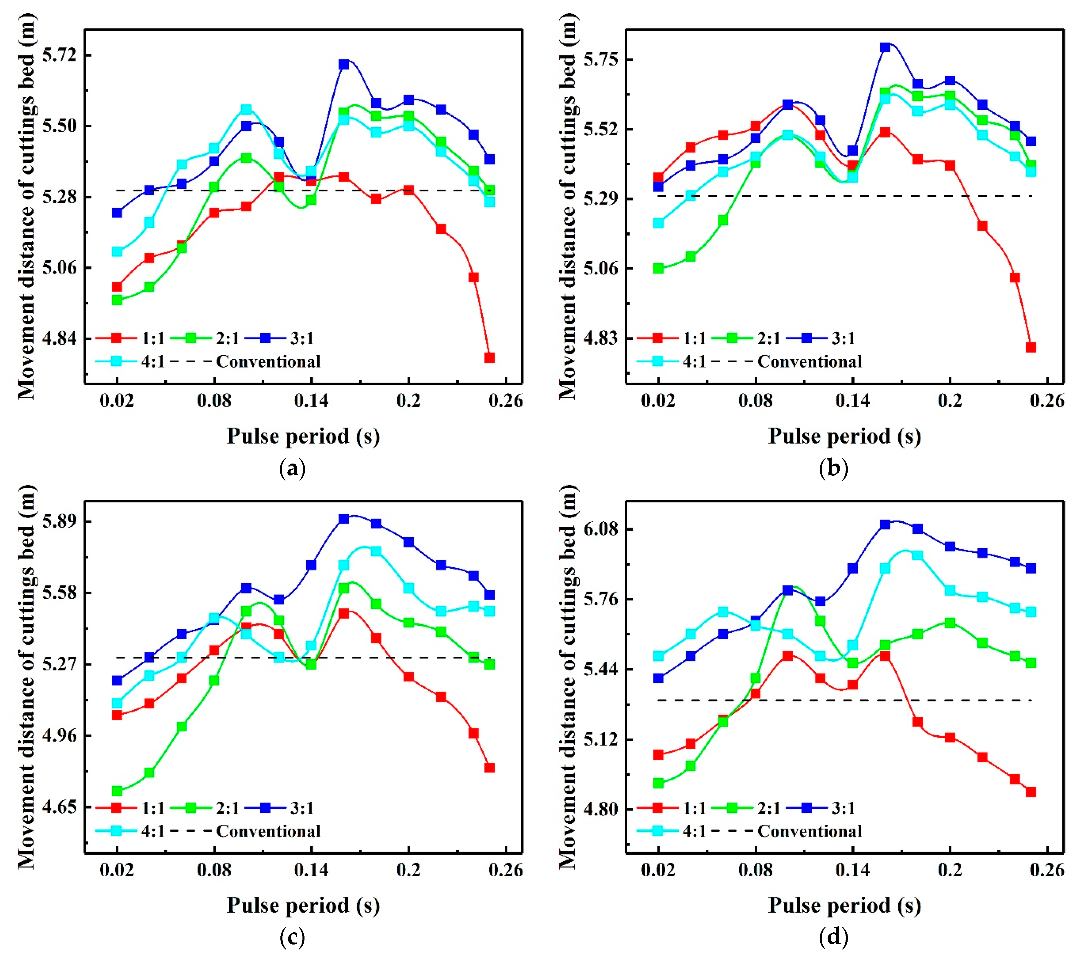
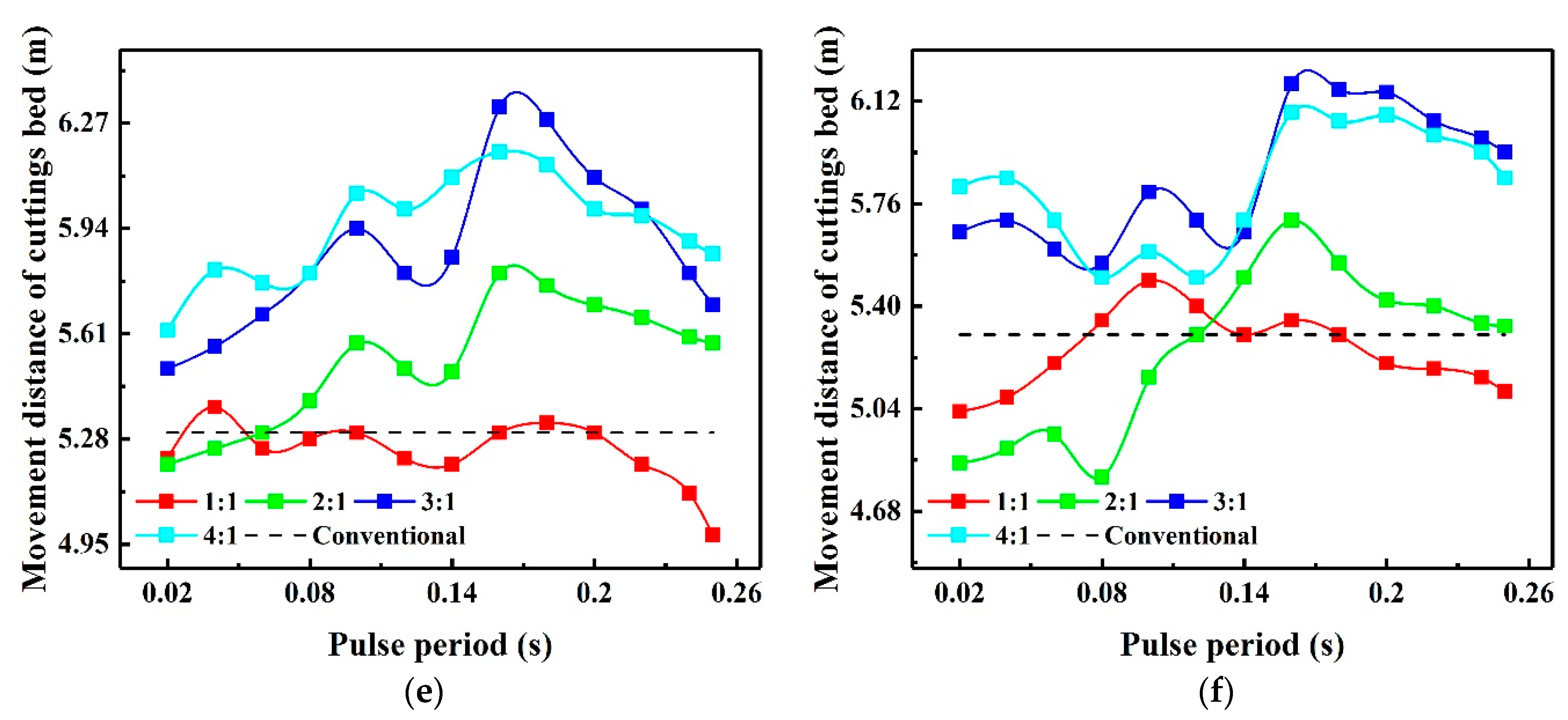
4.2. Pulse Parameter Sensitivity Analysis

Due to limited experiment conditions, it was not easy to simulate a particularly wide array of experimental parameters in this study. The parameters of pulsed drilling fluid cuttings transport yet merit further validation. The range of pulse parameters was adjusted in the numerical simulation, as shown in Figure 12. It appears that pulsed drilling fluid cuttings transport effects are better at pulse period T of 0.05 s, 0.25 s, and 0.5 s than 1 s; thus, this parameter was not optimal. When the pulse amplitude ratio was 10%, the cuttings bed movement distances were greater than 5% and 15%. The cuttings also appeared to move at a greater distance when the duty cycle was 2:1 than 1:1. The movement distance of the cuttings bed fluctuates with the increase of the pulse period, which indicates that the selection range of the pulse period needs to be narrowed. It remains necessary to further calculate the optimal-load pulse parameters beyond the scope of the present study.
According to the shunt mechanism and the characteristics of the pulse tool [41,42], when the pump displacement is 17.8 L/s, the range of pulse parameters is, as shown in Table 3. The conventional drilling fluid carries cuttings at 0%.
In the interval of 0.02–0.25 s, a cycle point is selected every 0.02 s as the working condition parameter. A three-layer numerical model was established with reference to the experimental conditions (and without considering the impact of borehole expansion and diameter reduction). The cuttings bed movement distance parameters were selected for comparison within a 10 s observation time. The initial cuttings bed length in the simulation was 0.4 m, the cuttings bed height (uniform layer and dispersed layer) was 15.24 mm, and the cuttings density was 80% or 50%.
Figure 13 shows the effect of different pulse parameters on cuttings transport. The result of 0% energy-carrying cuttings is represented by the dotted line in Figure 13. The numerical simulation results with different pulse amplitude ratios and duty cycles present similar characteristics under the same pulse period. By observing the numerical simulation results of any duty ratio, the movement distance of the cuttings bed gradually increases, then decreases after reaching a peak, then increases rapidly to another peak, and then decreases gradually. The cuttings transport distance is largest at T = 0.16 s.
When T = 0.16 s and the duty cycle is 3:1, the cuttings transport distance is largest when pulse amplitude ratio is 12.5%—it reaches 6.32 m, an increase of 19.25% compared to the conventional cuttings transport of 5.3 m. This indicates that the conventional drilling fluid is not effective in cuttings transport. In this case, the optimal parameters appear to be T = 0.16 s, q = 3:1, and pulse amplitude ratio of 12.5%.

5. Conclusions

This paper proposed a pulsed drilling fluid method to improve the cleanliness of the borehole in an inclined well section. An experiment and a three-layer numerical simulation model were used to explore a series of transport and drill equipment characteristics.
Experimental observations revealed that the cuttings in the inclined well section flow in the annulus in the form of a wave-bed. Under the action of the pulse, the drilling fluid can carry the cuttings move multiple times and across farther distances. Selecting a certain range of drill pipe speeds can effectively destroy the drill cuttings bed and reduce the height of the cuttings bed. Smaller cuttings have greater transport velocity and can be moved more efficiently. A smooth well wall also facilitates cuttings transport.
Numerical simulation results showed that cuttings transport in the inclined well section is influenced by the drilling fluid flow pattern. The optimal parameters of the pulse drilling fluid cuttings transport were found to be pulse amplitude ratio of 12.5%, T = 0.16 s, and q = 3:1. When these parameters are used, the movement distance of the cuttings bed is 6.32 m, which is 19.25% higher than that of the conventional drilling fluid cuttings transportation of 5.3 m.
The future direction of this research will be to develop cuttings bed destruction tools under cuttings transport of pulse drilling fluid.

Author Contributions

K.S. conceived and designed the experiment. K.S. conducted the experiment. K.S. conducted numerical simulation calculations. B.L. and X.Z. made some suggestions for the draft of the paper. K.S. revised and improved the paper based on these suggestions. All authors have read and agreed to the published version of the manuscript.

Funding

The lead author acknowledges support from the Natural Science Foundation of China (No. 51222406 and 51709231).

Institutional Review Board Statement

Not applicable.

Data Availability Statement

Data sharing not applicable.

Acknowledgments

The author is very grateful to Linxian Li for correcting the language.

Conflicts of Interest

The authors declare no competing interest.

Nomenclature

Symbols
CFD  Computational fluid dynamics
ROP  Rate of penetration
RPM  Revolutions per minute
A   Cross-section area
C   Solids concentration
Q   Flow rate
V   Velocity
E r   Entrainment rate
D r   Deposition rate
S   Perimeter
Φ   Solids packing porosity
ρ   Density
P   Pressure
τ   Shear stress
M   Dimensionless coefficient
k   Turbulent kinetic energy
ω   Specific dissipation rate
Y   Dissipation due to turbulence
Γ   Effective diffusivity
G   Generation due to mean velocity gradients
D ω   Cross-diffusion term
v   Velocity vector
K W & Y   Interphase momentum transfer coefficient between solid and liquid phase
ε   Volume fraction
d p   Particle diameter
C D   Drag coefficient
u   Viscosity
R e   Particles Reynolds number
K E   Interphase momentum transfer coefficient between solid and liquid phase
ϕ   Particles shape factor
K   Drag force between liquid phase and solid phase of Huilin–Gidaspow model
T   Interval between adjacent pulses
U m   Variation in the pulse from the minimum to the maximum
t w   Interval between two points along 0.5 at the leading edge and the trailing edge of the pulse
q   Ratio of the pulse width to the value of pulse period minus the pulse width
U max   Maximum pulse value
Subscripts
a   Wellbore
s   Solid phase
l   Fluid phase
u   Suspension layer
b m   Interface between uniform layer and dispersed layer
m   Dispersed layer
b   Uniform layer
s l i p   Slip between solid and liquid phase
u m   Interface between suspension layer and dispersed layer
m b   Interface between dispersed layer and uniform layer

References

  1. Amanna, B.; Movaghar, M.R.K. Cuttings transport behavior in directional drilling using computational fluid dynamics (CFD). J. Nat. Gas Sci. Eng. 2016, 34, 670–679. [Google Scholar] [CrossRef]
  2. Li, J.; Luft, B. Overview Solids Transport Study and Application in Oil-Gas Industry-Theoretical Work. In Proceedings of the International Petroleum Technology Conference, Kuala Lumpur, Malaysia, 10–12 December 2014. [Google Scholar] [CrossRef]
  3. Zhang, F.; Miska, S.; Yu, M.; Ozbayoglu, E.M.; Takach, N. Pressure profile in annulus: Solids play a significant role. J. Energy Resour. Technol. 2015, 137, 064502. [Google Scholar] [CrossRef]
  4. Larsen, T.I.; Pilehvari, A.A.; Azar, J.J. Development of a new cuttings-transport model for high-angle wellbores including horizontal wells. SPE Drill. Complet. 1997, 12, 129–136. [Google Scholar] [CrossRef]
  5. Duan, M.; Miska, S.; Yu, M.; Takach, N.E.; Ahmed, R.M.; Zettner, C.M. Transport of small cuttings in extended-reach drilling. SPE Drill. Complet. 2008, 23, 258–265. [Google Scholar] [CrossRef]
  6. Shadizadeh, S.R.; Zoveidavianpoor, M. An experimental modeling of cuttings transport for an Iranian directional and horizontal well drilling. Pet. Sci. Technol. 2012, 30, 786–799. [Google Scholar] [CrossRef]
  7. Ghasemi Kafrudi, E.; Hashemabadi, S.H. Numerical Study on Effects of Drilling Mud Rheological Properties on the Transport of Drilling Cuttings. J. Energy Resour. Technol. 2016, 138, 012902. [Google Scholar] [CrossRef]
  8. Yu, M.; Takach, N.E.; Nakamura, D.R.; Shariff, M.M. An Experimental Study of Hole Cleaning under Simulated Downhole Conditions. In Proceedings of the SPE annual Technical Conference and Exhibition. Society of Petroleum Engineers, Anaheim, CA, USA, 11–14 November 2007. [Google Scholar] [CrossRef]
  9. Ozbayoglu, M.E.; Saasen, A.; Sorgun, M.; Svanes, K. Effect of pipe rotation on hole cleaning for water-based drilling fluids in horizontal and deviated wells. In Proceedings of the IADC/SPE Asia Pacific Drilling Technology Conference and Exhibition. Society of Petroleum Engineers, Jakarta, Indonesia, 25–27 August 2008. [Google Scholar] [CrossRef]
  10. Sorgun, M.; Aydin, I.; Ozbayoglu, M.E. Friction factors for hydraulic calculations considering presence of cuttings and pipe rotation in horizontal/highly-inclined wellbores. J. Pet. Sci. Eng. 2011, 78, 407–414. [Google Scholar] [CrossRef]
  11. Ofei, T.N.; Yaaqob, S.Y. Numerical simulation of transport behaviour of small cuttings in extended reach wells. Int. J. Oil Gas Coal Technol. 2019, 21, 149–168. [Google Scholar] [CrossRef]
  12. Piroozian, A.; Ismail, I.; Yaacob, Z.; Babakhani, P.; Ismail, A.S.I. Impact of drilling fluid viscosity, velocity and hole inclination on cuttings transport in horizontal and highly deviated wells. J. Pet. Explor. Prod. Technol. 2012, 2, 149–156. [Google Scholar] [CrossRef]
  13. Kim, Y.J.; Woo, N.S.; Hwang, Y.K.; Kim, J.H.; Han, S.M. Transport of small cuttings in solid-liquid flow with inclined slim hole annulus. J. Mech. Sci. Technol. 2014, 28, 115–126. [Google Scholar] [CrossRef]
  14. Cho, H.; Shah, S.N.; Osisanya, S.O. A three-segment hydraulic model for cuttings transport in coiled tubing horizontal and deviated drilling. J. Can. Pet. Technol. 2002, 41. [Google Scholar] [CrossRef]
  15. Ramadan, A.; Skalle, P.; Saasen, A. Application of a three-layer modeling approach for solids transport in horizontal and inclined channels. Chem. Eng. Sci. 2005, 60, 2557–2570. [Google Scholar] [CrossRef]
  16. Guo, X.L.; Wang, Z.M.; Long, Z.H. Study on three-layer unsteady model of cuttings transport for extended-reach well. J. Pet. Sci. Eng. 2010, 73, 171–180. [Google Scholar] [CrossRef]
  17. Zhang, F.; Miska, S.; Yu, M.; Ozbayoglu, E. A unified transient solid-liquid two-phase flow model for cuttings transport-modelling part. J. Pet. Sci. Eng. 2018, 166, 146–156. [Google Scholar] [CrossRef]
  18. Han, S.M.; Hwang, Y.K.; Woo, N.S.; Kim, Y.J. Solid–liquid hydrodynamics in a slim hole drilling annulus. J. Pet. Sci. Eng. 2010, 70, 308–319. [Google Scholar] [CrossRef]
  19. Ofei, T.N.; Irawan, S.; Pao, W. CFD method for predicting annular pressure losses and cuttings concentration in eccentric horizontal wells. J. Pet. Eng. 2014. [CrossRef] [Green Version]
  20. Sun, X.; Wang, K.; Yan, T.; Shao, S.; Jiao, J. Effect of drillpipe rotation on cuttings transport using computational fluid dynamics (CFD) in complex structure wells. J. Pet. Explor. Prod. Technol. 2014, 4, 255–261. [Google Scholar] [CrossRef] [Green Version]
  21. Akhshik, S.; Behzad, M.; Rajabi, M. CFD–DEM approach to investigate the effect of drill pipe rotation on cuttings transport behavior. J. Petrol. Sci. Eng. 2015, 127, 229–244. [Google Scholar] [CrossRef]
  22. Heydari, O.; Sahraei, E.; Skalle, P. Investigating the impact of drillpipe’s rotation and eccentricity on cuttings transport phenomenon in various horizontal annuluses using computational fluid dynamics (CFD). J. Pet. Sci. Eng. 2017, 156, 801–813. [Google Scholar] [CrossRef]
  23. Epelle, E.I.; Gerogiorgis, D.I. Transient and steady state analysis of drill cuttings transport phenomena under turbulent conditions. Chem. Eng. Res. Des. 2017, 131, 520–544. [Google Scholar] [CrossRef] [Green Version]
  24. Ozbayoglu, M.E.; Saasen, A.; Sorgun, M.; Svanes, K. Critical fluid velocities for removing cuttings bed inside horizontal and deviated wells. Pet. Sci. Technol. 2010, 28, 594–602. [Google Scholar] [CrossRef]
  25. Wang, R.H.; Du, Y.K.; Ni, H.J.; Ma, L. Hydrodynamic analysis of suck-in pulsed jetin well drilling. J. Hydrodyn. 2011, 23, 34–41. [Google Scholar] [CrossRef]
  26. Shi, H.; Li, G.; Guo, B.; He, Z. Hydraulic pulse jet: Test of characteristics and field applications in ultra-deep wells. J. Nat. Gas Sci. Eng. 2015, 27, 200–206. [Google Scholar] [CrossRef]
  27. Hongna, Q.U.; Gensheng, L.I.; Jiang, D. Mechanisms and Application for Hydraulic Pulsed Cavitating Jet Generator. Adv. Pet. Exp. Dev. 2016, 12, 1–12. [Google Scholar] [CrossRef]
  28. Li, G.; Shi, H.; Liao, H.; Shen, Z.; Niu, J.; Huang, Z.; Luo, H. Hydraulic pulsed cavitating jet-assisted drilling. Pet. Sci. Technol. 2009, 27, 197–207. [Google Scholar] [CrossRef]
  29. Li, G.; Shi, H.; Niu, J.; Huang, Z.; Tian, S.; Song, X. Hydraulic Pulsed Cavitating Jet Assisted Deep Drilling: An Approach to Improve Rate of Penetration. In Proceedings of the International Oil and Gas Conference and Exhibition in China. Society of Petroleum Engineers, Beijing, China, 8–10 June 2010. [Google Scholar] [CrossRef]
  30. Shi, H.; Li, G.; Huang, Z.; Shi, S. Properties and testing of a hydraulic pulse jet and its application in offshore drilling. Pet. Sci. 2014, 11, 401–407. [Google Scholar] [CrossRef] [Green Version]
  31. Fu, J.; Li, G.; Shi, H.; Niu, J.; Huang, Z. 2012 A novel tool to improve the rate of penetration--hydraulic-pulsed cavitating-jet generator. SPE Drill. Complet. 2012, 27, 355–362. [Google Scholar] [CrossRef]
  32. Cheng, R.; Ge, Y.; Wang, H.; Ni, H.; Zhang, H.; Sun, Q. Self-Oscillation Pulsed Percussive Rotary Tool Enhances Drilling Through Hard Igneous Formations. In Proceedings of the IADC/SPE Asia Pacific Drilling Technology Conference and Exhibition. Society of Petroleum Engineers, Tianjin, China, 9–11 July 2012. [Google Scholar] [CrossRef]
  33. Cui, L.; Zhang, F.; Wang, H.; Ge, Y.; Zhuo, L.; Li, H. Development and Application of Adjustable Frequency Pulse Jet Generating Tool to Improve Rate of Penetration in Deep Wells. In Proceedings of the IADC/SPE Asia Pacific Drilling Technology Conference and Exhibition, Tianjin, China, 9–11 July 2012. [Google Scholar]
  34. Wang, M.; He, J.; He, Y.; Xu, Y.; Zhao, J. Application of Down-hole Screw-type Pressure Intensifier for ROP Enhancement. In Proceedings of the IADC/SPE Asia Pacific Drilling Technology Conference and Exhibition, Tianjin, China, 9–11 July 2012. [Google Scholar]
  35. Shakib, J.T.; Ghaderi, A.; Shahri, A.A. 2012 Analysis of hydraulic fracturing length and aperture on the production rate in fractured reservoir. Resuscitation 2015, 96, 180–185. [Google Scholar] [CrossRef] [Green Version]
  36. Shakib, J.T.; Ghaderi, A.; Shahri, A.A. Analysis of hydraulic fracturing in fractured reservoir: Interaction between hydraulic fracture and natural fractures. Science 1988, 239, 1313. [Google Scholar] [CrossRef] [Green Version]
  37. Pang, B.; Wang, S.; Liu, G.; Jiang, X.; Lu, H.; Li, Z. Numerical prediction of flow behavior of cuttings carried by Herschel-Bulkley fluids in horizontal well using kinetic theory of granular flow. Powder Technol. 2018, 329, 386–398. [Google Scholar] [CrossRef]
  38. Akhshik, S.; Behzad, M.; Rajabi, M. CFD-DEM simulation of the hole cleaning process in a deviated well drilling: The effects of particle shape. Particuology 2016, 25, 72–82. [Google Scholar] [CrossRef]
  39. Sifferman, T.R.; Becker, T.E. Hole Cleaning in Full-Scale Inclined Wellbores. SPE Drill. Eng. 1992, 7, 115–120. [Google Scholar] [CrossRef]
  40. Zhu, X.H.; Shen, K.Y.; Li, B.; Lv, Y.X. Cuttings Transport Using Pulsed Drilling Fluid in the Horizontal Section of the Slim-Hole: An Experimental and Numerical Simulation Study. Energies 2019, 12, 3939. [Google Scholar] [CrossRef] [Green Version]
  41. Zhu, X.H.; Sun, C.; Tong, H. Distribution features, transport mechanism and destruction of cuttings bed in horizontal well. J. Hydrodyn. 2013, 25, 628–638. [Google Scholar] [CrossRef]
  42. Jia, Y.J.; Tong, H. Structure security analysis of cuttings falling-prevention tool for gas drilling. China Petrol. Mach. 2009, 37, 9–11, 89. [Google Scholar] [CrossRef]
Figure 1. Inclined well annulus.
Energies 14 02141 g001
Figure 2. Annulus grid of inclined well section.
Energies 14 02141 g002
Figure 3. Experimental diagram.
Energies 14 02141 g003
Figure 4. Main equipment for cuttings transport experiment. (a) Visual pipe string system; (b) transportation pipeline.
Energies 14 02141 g004
Figure 5. Cuttings flow pattern.
Energies 14 02141 g005
Figure 6. Impact of different cuttings sizes on cuttings transport. (a) Conventional drilling fluid; (b) pulsed drilling fluid.
Energies 14 02141 g006
Figure 7. Impact of different drill pipe rotation speeds on cuttings transport.
Energies 14 02141 g007
Figure 8. Impact of cuttings bed mass on cuttings transport.
Energies 14 02141 g008
Figure 9. Impact of roughness height on cuttings transport.
Energies 14 02141 g009
Figure 10. Sensitivity analysis of experiment pulse parameters.
Energies 14 02141 g010
Figure 11. Comparison of experimental and simulation results.
Energies 14 02141 g011
Figure 12. Comparison of experiment and simulation pulse parameter results.
Energies 14 02141 g012
Figure 13. Effect of pulse amplitude ratio. (a) 2.5%; (b) 5%; (c) 7.5%; (d) 10%; (e) 12.5%; (f) 15%.
Energies 14 02141 g013aEnergies 14 02141 g013b
Table 1. Experiment parameters.
ParameterSimulation ValueUnits
Drill pipe diameter88.9mm
Annulus diameter152.4mm
Hole deviation angle60degree
Drill pipe rotation speed0, 60, 120, 180rpm
Drilling fluid density1200kg/m3
Particle density2600kg/m3
Particle diameter1, 2, 3, 4, 5mm
Cuttings bed mass0.25, 0.5, 1, 1.5, 2kg
Roughness height0, 1, 3, 5mm
Table 2. Pulse experimental parameters.
ParameterSimulation ValueUnits
Pulse amplitude ratios0, 5, 10, 15%
Pulse periods (T)1, 2, 3s
Duty cycles (q)1:1, 2:1
Table 3. Numerical simulation of pulse parameters.
ParameterSimulation ValueUnits
Pulse amplitude ratios0, 2.5, 5, 7.5, 10, 12.5, 15%
Pulse periods (T)0.02–0.25s
Duty cycles (q)1:1, 2:1, 3:1, 4:1
Publisher’s Note: MDPI stays neutral with regard to jurisdictional claims in published maps and institutional affiliations.

