Article

A Parameter Independent Stator Current Space-Vector Reference Frame-Based Sensorless IPMSM Drive Using Sliding Mode Control

by
Mohammadreza Moradian
1,2,*,
Jafar Soltani
3,
Mohamed Benbouzid
4,* and
Abbas Najjar-Khodabakhsh
1
1
Department of Electrical Engineering, Najafabad Branch, Islamic Azad University, Najafabad 85141-43131, Iran
2
Smart Microgrid Research Center, Najafabad Branch, Islamic Azad University, Najafabad 85141-43131, Iran
3
Faculty of Electrical and Computer Engineering, Isfahan University of Technology, Isfahan 84156-83111, Iran
4
Institut de Recherche Dupuy de Lôme (UMR CNRS 6027 IRDL), University of Brest, 29238 Brest, France
*
Authors to whom correspondence should be addressed.
Energies 2021, 14(9), 2365; https://doi.org/10.3390/en14092365
Submission received: 28 February 2021 / Revised: 15 April 2021 / Accepted: 19 April 2021 / Published: 22 April 2021
(This article belongs to the Special Issue Electric Machines and Drive Systems for Emerging Applications)

Abstract

:
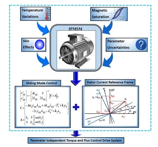
In this paper, a sliding mode control is presented for direct torque and stator flux control of interior permanent magnet synchronous motor in a rotor speed sensorless drive system. The control scheme is developed in a specific synchronous rotating reference frame (X-Y) in which the stator current space vector coincides with the direct (X) axis. For this control technique no need to have any knowledge of machine parameters such as stator two-axis inductances, rotor permanent magnets flux linkage, and even the rotor initial position. However, the on-line actual stator resistance value is required to estimate the stator flux components in the stator stationary two-axis reference frame. In this control strategy, two simple methods are described for estimating the rotor speed and stator resistance. Some simulation and experimental results are presented to support the validity and effectiveness of the proposed control scheme.

Graphical Abstract

1. Introduction

High efficiency and power factor, high torque/ampere ratio, high reliability, and rugged structure of interior permanent magnet synchronous motor (IPMSM) have made it common in the industry. The performance of this motor is greater than the performance of the surface-mounted permanent magnet synchronous motor and the induction motor. Since the past decade, IPMSM’s variable-speed applications have been seen. Also in Europe, the use of the IPMSM for electric vehicle traction and hybrid electric vehicle applications has been discussed. In these applications, the main features of IPMSM are uncomplicated construction with conventional 3-phase stator windings, with low current density, and a rotor with inner fragmental permanent magnets [1,2,3].
A direct flux vector control scheme employs one proportional-integral (PI) controller, space vector modulation (SVM) with a fixed switching frequency, and low torque ripple are proposed in [4,5]. Utilizing the (x-y) stator flux field-oriented reference frame and (d-q) rotor reference frame of IPMSM, the ordinary current PI controller has been used for direct torque (DT) and flux control of this machine drive system [4,5,6,7].
Notice that the system strength and stability are weak against the motor parameter variations and load disturbances with conventional PI controller [8]. One method refers to the adaptive input-output feedback linearization control (AIOC) scheme among the efficient nonlinear control methods [9,10,11]. In [9,10,11], the full knowledge of actual machine inductances (Ld, Lq), stator resistance (rs), rotor permanent magnets flux linkage (λm), and rotor initial position (θr0) are necessary to develop the control strategy. The research works described in [10,11] need the mechanical rotor speed sensor. Besides, the control methods proposed in these references have been supported only by simulation results.
Recently, sliding mode control (SMC) has been used in variable structure control strategies in different studies of AC servo-drive control systems [12,13,14,15,16]. Many good properties such as good performance against non-modeled dynamics, can be presented by SMC insensitivity to external disturbance, parameter variations, and fast dynamic response [17]. A SMC has been outlined in [18] for DT and flux control of the IPMSM drive, as a result, the rotor speed is estimated by an extended Kalman filter observer. Notice that this mentioned observer needs to know the actual machine parameters (Ld, Lq, rs, λm, θr0). Furthermore, a sliding mode observer is used to estimate the IPMSM parameters, stator flux, rotor position, and the rotor angular speed in [19,20].
So far the only method used for DT and stator flux control of IPMSM that does not need to know the full acknowledge of the motor parameters (d-q) inductances (Ld, Lq) and the rotor permanent magnets linkage fluxes (λm) has been developed in the stator flux field-oriented reference frame, which uses the usual PI controllers [7]. Two separate observers have been developed for the estimation of stator resistance and rotor speed. These observers need to know the actual values of motor inductances (Ld, Lq) and also the rotor permanent magnets flux linkages (λm). In [7], a practical look-up table has been acquired for the parameter (Ld) as a function of the stator current (Is), however, the nominal value of (Lq) has been used in the abovementioned observers. In fact, the control method described in [7] is motor parameter-dependent, although the stator flux field reference frame has been used.
Therefore, the control method schemes applied to IPMSM drive systems so far, have been mostly the IPMSM drive systems dependent parameters control approaches. Although a few authors and researchers tried to propose some control schemes that could solve the problems that counter fronted with these electric motor drive systems [17,18,19,20,21,22,23,24,25], the non-linearity problems such as magnetic saturation, skin effects, and temperature as well as the uncertainties that exist in these electric motion drive system parameters had not been completely solved until the electric independent control schemes reported in [26,27]. It may be noted that the IPMSM rotor frame two-axis stator reactances, stator resistance, and the rotor permanent magnets flux linkage cataloged values, all seriously vary during the drive system different operating conditions because of the above-mentioned problems. It may also be noted that the IPMSM drive system rotor permanent magnets linkage fluxes mostly vary with temperature. However, the stator resistance and its two-axis reactances could roughly vary about fifty to one hundred percent of their nominal values. One way to come up with these problems is online estimating the mentioned parameters under persistency of excitation (PE) condition to be valid [25]. It is not necessary to mention that there is no way for online estimation of IPMSM rotor flux linkages both in theory and practice.
One more important point that should be noted in the machine drive systems like IPMSM drive systems is that their electric parameters given in the corresponding catalogs are measured in the machine nominal operating conditions work as the main frequency voltage-fed motors. Therefore the simulation and practical results obtained by these uncertain parameters are really not accurate and have considerable errors compared to their actual perfect results.
In [25], a Lyapunov-based adaptive control scheme has been explained that online estimates the IPMSM stator two-axis reactances, and a simple method has also been proposed for the stator resistance estimation. That method controls the decoupled reference values relating to stator squared flux and the motor drive system electromagnetic generated torque. The control method of [25], still needs to know the rotor initial mechanical position angle as well as the value of rotor flux linkages. It also has a high computation time and computer saving memory. Its main weakness is that for different drive system operating conditions, the estimated stator two-axis reactances converge to their pre-decided chosen values, having proved the validation of the PE condition. That means still the values of the mentioned parameters are uncertain and the controller law produces the step by step two-level three-phase SVM-PWM inverter voltage references based on using the nominal values of the stator two-axis reactances.
To solve the mentioned problems, a real independent parameter control scheme has been reported in [26] that used the stator two-axis voltage equations obtained in the stator current space-vector oriented two-axis reference frame. In these equations, the two-axis stator reactances and the rotor flux linkages parameter have not appeared and therefore the mentioned non-linearity and uncertainty problems, have not existed and have really been solved. The proposed method doesn’t need to know the values of rotor initial mechanical position angle and the rotor flux linkages as mentioned earlier. That control system has used the AIOC scheme in order to decoupled control the reference values of the stator squared flux and the motor drive system electromagnetic generated torque as well as to on-line estimate the value of stator resistance.
Also, another independent parameter control approach based on using the stator voltage equations obtained in the stator flux space-vector field-oriented reference frame has been described in [27]. The independent parameters control technique proposed in this paper is in fact a continuation of the research work reported in [26] with the replacement of the sliding mode control scheme for the AIOC scheme that has been used in [26]. This controller has a fast dynamic response and is a simple and easy implementation control scheme and is a good stable and robust control method with a high disturbance rejection characteristic compared to other nonlinear control methods.
In this paper, a sliding mode DT control is described for IPMSM drive which is developed in the stator current space-vector oriented reference frame (X-Y) where X coincides with the stator current space-vector. In this reference frame, both the two-axis stator voltage equations have derivative terms, and it makes the implementation of the SMC easy.
SMC has been chosen in this paper because of its fast and rapid dynamic response as well as because of its easy practical implementation and not really needing to use its other inherent characteristics as mentioned earlier. Using the SMC approach in either of the electric machine drive systems or in controlling the power electronic converters that are linked with PWM voltage inverters, can be easily prevented the three-phase PWM voltage inverters to be saturated. That can be achieved just by quickly reducing the SMC gain automatically. The PWM voltage inverter saturation means that the amplitude of its reference voltages suddenly changed to a level very close or higher than the DC-link capacitor voltage. In this case, the PWM operation mode of the inverter failed and it rapidly converted to a simple square wave shape voltage inverter that could cause the electric motor drive systems used to be magnetically saturated heavily and quickly. In this condition, the mentioned system protection needs to operate faster in order to switch off the inverter from the rest of the hardware system equipment. Imagine the three-phase induction motor drives that are usually used in the steel mill making factories or in navigation systems and the IPMSM motor drive systems that have recently been used in electric vehicles, in aircrafts systems, and a few electric army weapons, if either of their PWM voltage inverters is quickly saturated, that can be ended to very dangerous events or huge economic losses. The second reason that the SMC scheme has been used in this paper, has been to complete our past research works in this field. Moreover, the same developed and implemented hardware system including the same two-level three-phase SVM-PWM voltage sensorless inverter that has been explained in [27] and originally was being taken from [28] used to get the practical results for the motor drive system under consideration. Moreover, in contrast to the method discussed in [7,27], in this paper, simple and fast rotor speed and stator resistance observers are presented which do not need to know the IPMSM two-axis inductances.
Noticing that our simulation results are obtained by solving the IPMSM voltage equations in the rotor (d-q) reference frame, one needs to know the motor inductances (Ld, Lq) and also the rotor permanent magnets flux linkages (λm). Therefore the full acknowledgment of the machine parameters is only required for our simulation results and not really in our experimental implementation. Simulation and experimental results verify the effectiveness and capability of the proposed control method.
Lastly, it is worth mentioning that the simulated and practical obtained results shown in the present paper, are totally precise and accurate similar to actual results and that is because of using an independent parameter control scheme as mentioned before.

2. Analytical Approach

2.1. Sliding Mode Control of Ipmsm

Referring to Figure 1, the stator-current space vector angle with respect to the direct axis of stator stationary reference frame is obtained by:
ρ ^ i = T a n 1 ( i Q S i D S )
where iDS and iQS are the stator currents in the (DS-QS) stationary reference frame.
As shown in Figure 1, applying the following transformation matrix, the machine variables are transformed from (DS-QS) stationary reference frame to stator current space vector oriented reference frame (X-Y):
[ F S X F S Y ] = [ C o s ( ρ i ) S i n ( ρ i ) S i n ( ρ i ) C o s ( ρ i ) ] [ F D S F Q S ]
where F denotes the voltage, current, or stator flux linkages.
Also, the machine state-space equation in the (X-Y) reference frame is given by [29]:
X ˙ = F ( X ) + G ( X )   V
with:
X = [ x 1 x 2 ] T = [ λ S X λ S Y ] T
F ( X ) = [ f 1 f 2 ] = [ r s i S X + ω e i λ S Y ω e i λ S X ]
G ( X ) = [ 1 0 0 1 ] ;           V = [ v S X v S Y ]
where vSX and vSY are X-Y axes stator voltages, iSX and iSY are X-Y axes stator currents, λSX and λSY are X-Y axis stator flux linkages, rs is the stator resistance, and ωei is the stator current electrical angular speed.
Defining the motor output variables as:
y 1 = T e = A λ S Y i S X   y 2 = λ S 2 = ( λ S X ) 2 + ( λ S Y ) 2
where Te is the motor electromagnetic torque and λs is the amplitude of the stator linkage flux.
Therefore the motor error dynamics model in (X-Y) reference frame is obtained as:
e ˙ = H + D   U
with:
e ˙ = [ e ˙ T e ˙ λ ] ; H = [ A ω e i i S X λ S X + A λ S Y d i S X d t d T e * d t 2 r s i S X λ S X d ( λ s * ) 2 d t ]   ; D = [ A i S X 0 2 λ S Y 2 λ S X ] ; U = [ v S Y v S X ]
where:
e T = T e T e * e λ = λ S 2 λ S * 2
where superscript “*” denotes the referenced value.
Using the sliding mode switching surfaces defined by:
S 1 = e T + k 1 e T   d t S 2 = e λ + k 2 e λ   d t
where k1 and k2 are positive coefficients. Referring to [30], when the system states reach the sliding manifold and slide along the surface, it is approved that:
S 1 = S ˙ 1 = e ˙ T + k 1 e T = 0 S 2 = S ˙ 2 = e ˙ λ + k 2 e λ = 0
Combining (8), (10), and (12) results in:
S ˙ = C + D U
S ˙ = [ S ˙ 1 S ˙ 2 ] ; C = [ A ω e i i S X λ S X + A λ S Y i ˙ S X T ˙ e * + k 1 e T 2 r s i S X λ S X λ ˙ S * 2 + k 2 e λ ]  
From (13) and (14), the equivalent SMC law is:
U = D 1 C
To guarantee the sliding mode reaching phase, the following control effort is finally used:
U * = D 1 { C + Λ } ,     Λ = [ λ 1 0 0 λ 2 ] [ s a t ( S 1 ) s a t ( S 2 ) ]
where λ1 and λ2 are the sliding mode’s positive control gains and φi is the positive switching coefficient. sat(Si) is the well-known saturation function used to reduce the SMC chattering effect [30].
Candidating a Lyapunov function as:
V = 1 2 S 1 2 + 1 2 S 2 2   0
Derivative of V with respect to time results in:
V ˙ = S 1 S ˙ 1 + S 2 S ˙ 2
Combining (13) and (18) gives:
V ˙ = λ 1 S 1 s a t ( S 1 ) λ 2 S 2 s a t ( S 2 )
{ i f       S i < 0 S ˙ i = + λ i S ˙ i S i < 0 i f       S i > 0 S ˙ i = λ i S ˙ i S i < 0      i = 1 , 2      S ˙ 1 S 1 + S ˙ 2 S 2 < 0
Therefore V ˙ < 0 and as a result, the control system becomes asymptotically stable.
As isx needed to build up first, therefore, the following approximate equation is used to calculate the Y-axis reference voltage for a few initial steps:
v S Y * = ω e i λ S X
After building up the stator current (isx), the actual equation corresponding to v*SY given in (16) is used. It is worth mentioning that in the first step of calculations, it is required to estimate the two stator axis fluxes (λSX(0), λSY(0)). These are acquired from rotor magnet flux according to the following equations:
λ S X ( 0 )   = λ m C o s ( ρ i ( 0 ) ) λ S Y ( 0 )   = λ m S i n ( ρ i ( 0 ) )
From (22), the initial current vector angle ρi(0) and even the rotor permanent magnets flux linkage (λm) do not need to be the actual values. The error only appears in the first step of estimating the stator fluxes, if the wrong values for these quantities are obtained, but in the subsequent steps, this error is automatically corrected.

2.2. Ipmsm Rotor-Speed Estimation

Generally, an absolute encoder can detect the accurate rotor position. This sensor is extremely sensitive to vibration and ambient temperature. To overcome these problems, the estimated values of the rotor position and angular speed are used in the sensorless control method instead of using speed and position sensors.
Referring to Figure 1, one can be obtained:
ρ ^ i = δ ^ i + θ ^ r    d ρ ^ i d t = d δ ^ i d t + ω r
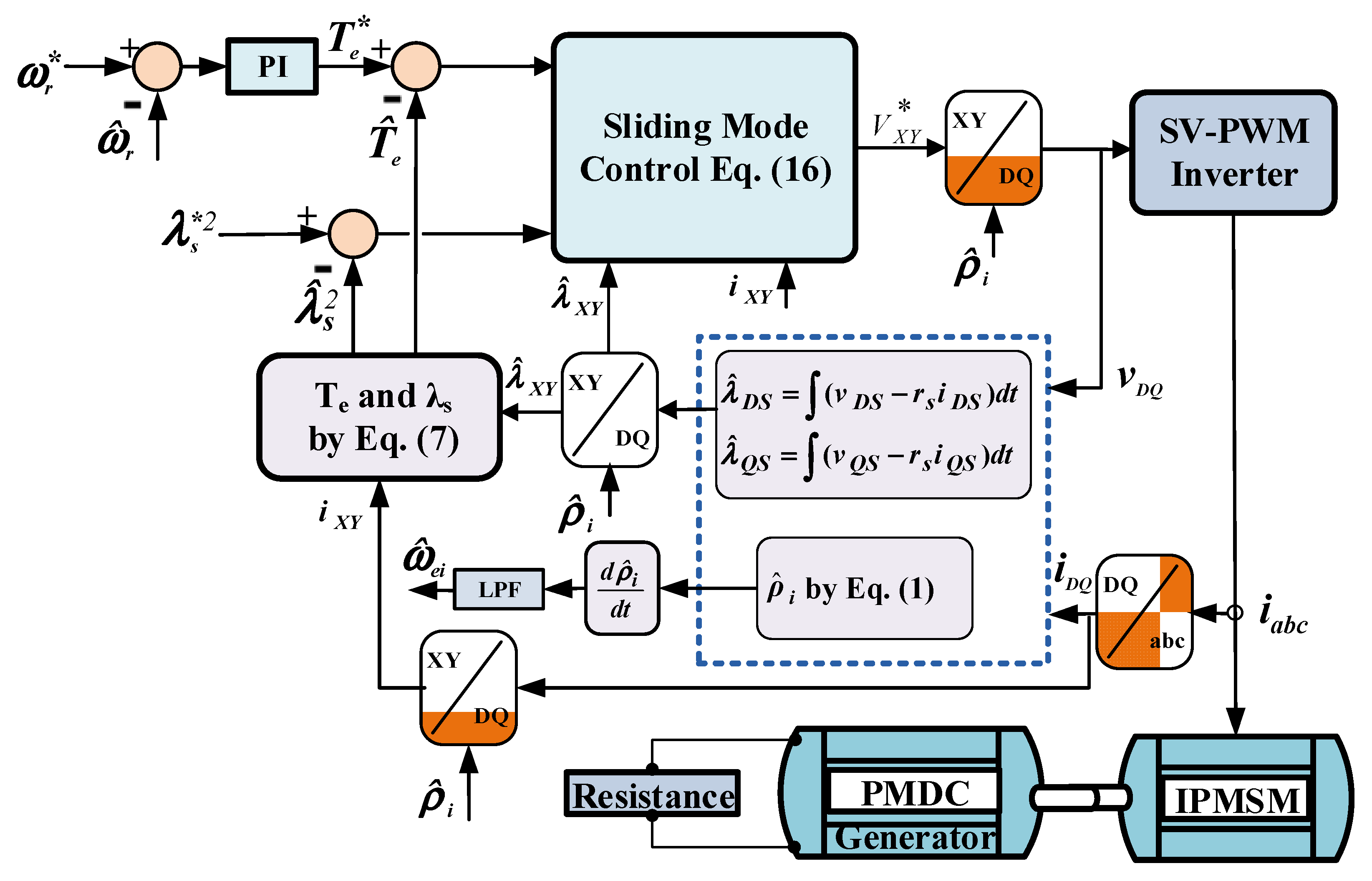
where ρ ^ i is the estimated angle of space current vector obtained from (1), δ ^ i is the stator currents space vector with respect to the rotor d axis. In this control method according to the block diagram shown in Figure 2, the motor speed is estimated online by taking the time derivative of stator-current space vector angle.
Referring to (23), it is recognized that in transient state conditions, the rotor electrical angular speed is not exactly equal to the derivative of ρ ^ i due to the derivative term of δ ^ i . Since the IPMSM has a fast dynamic response, consequently, the high-frequency variation generated in the rotor speed ω ^ r due to the term of ( d δ ^ i d t ) is filtered out by a low pass filter (LPF) that we have used in Figure 2.

2.3. Stator Resistance Estimation

As shown in Figure 3, a conventional PI controller is employed for stator resistance estimation. The input of this PI controller is the error between the online stator current reference ( I s * ) and its corresponding actual value ( I s ) which is obtained as:
I s * = i s x * = T e * λ s y
The error between the real stator current and its reference is passed through an LPF. The reason why the cut-off frequency of LPF is chosen to be very low is that it should attenuate the high-frequency components. One may note that inaccuracy in stator resistance causes an inaccuracy in the estimated stator flux components in (DS-QS) stationary axis.

3. Results

3.1. Simulation Results

The control approach described in this paper is practically a motor parameter independent method as described in the paper introduction part. This control scheme has been implemented in the stator currents space vector-oriented reference frame which needs only stator two-axis currents and stator two-axis flux linkages. The stator currents are sampled by the sensors and stator two-axis fluxes are obtained in the stationary stator two-axis reference frame which no need to know the machine inductances. That means, the proposed control scheme only needs to know the stator resistance estimation and no need to have any knowledge of (Ld, Lq, λm) and even rotor initial position (θr0) for practical implementation.
Noticing that, the simulation results are obtained based on solving the IPMSM voltage equations in the rotor (d-q) reference frame which needs to know the motor inductances (Ld, Lq) and also the rotor permanent magnets flux linkages (λm). Therefore the full acknowledgment of the machine parameters is only required for our simulation results and not really need for our experimental implementation. Moreover, in these simulation conditions, we consider some step changes in motor parameters of (Ld, Lq, rs), and it has been shown that the motor dynamic performance is still robust and stable. Simulation results are obtained for an IPMSM with parameters given in Table 1. Table 2 demonstrates the controller parameters.
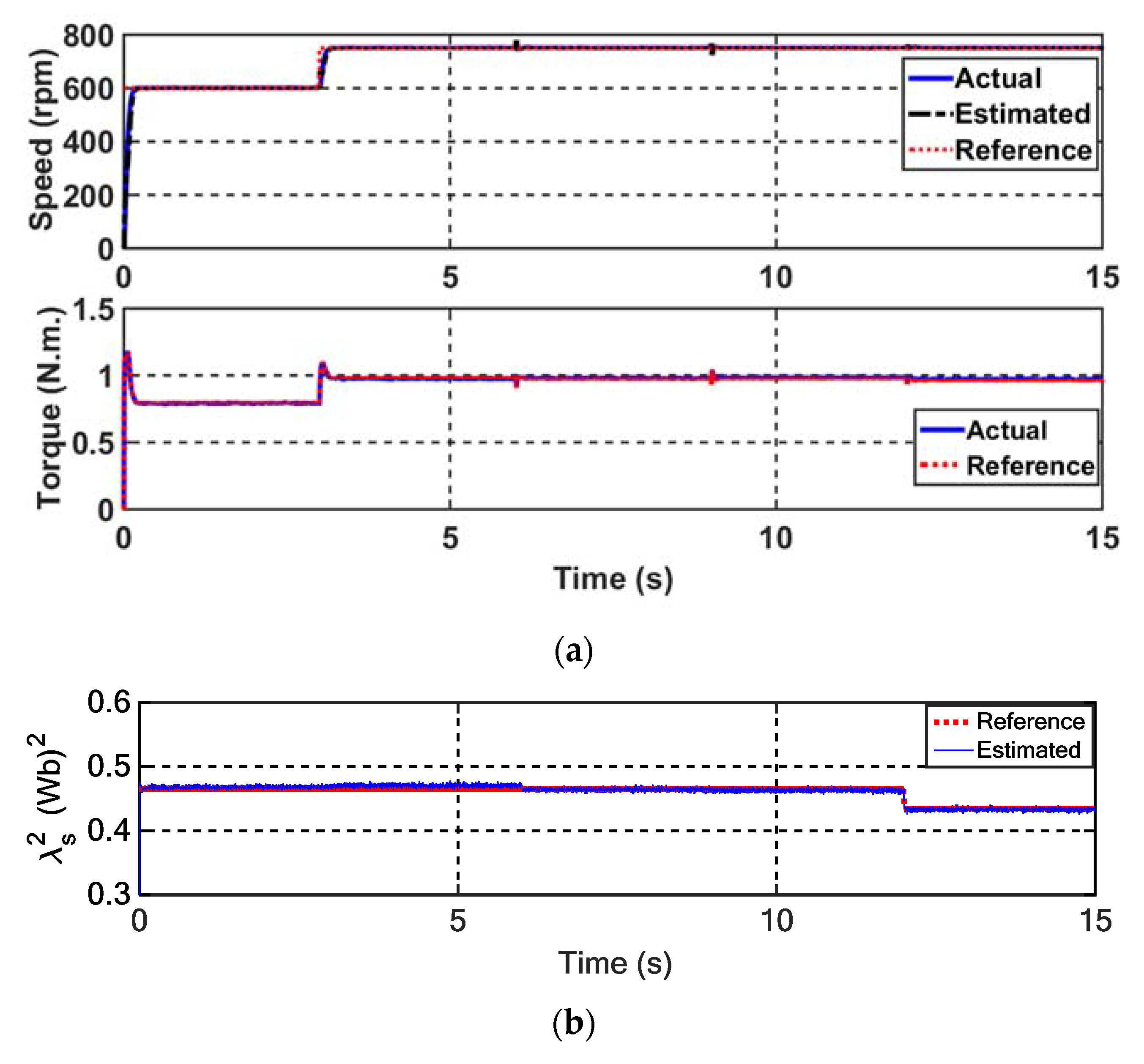
Considering the magnitude of squared stator reference flux of λs*2 = 0.465 (Wb)2, the speed of the rotor at t = 0 s is stepped from zero to 600 rpm and at t = 3 s changes from 600 rpm to 750 rpm. The stator resistance of the motor is changed from rs = rsn to rs = 1.2 rsn at t = 6 s; motor d and q inductances stepping reducing from nominal values to 0.8 of nominal values at t = 9 s; and finally the λs*2 is stepped down from 0.465 (Wb)2 to 0.435 (Wb)2 at t = 12 s, in order to explore the impact of parameter variations on the motor performance. Simulation results of these tests are indicated in Figure 4.
Referring to Figure 4a,b, the average of the electromagnetic torque and stator flux, accurately follow their reference corresponded values. Also, the motor parameter step changes have not affected the motor stability and its dynamic performance.

3.2. Experimental Methodology

3.2.1. Experimental Setup

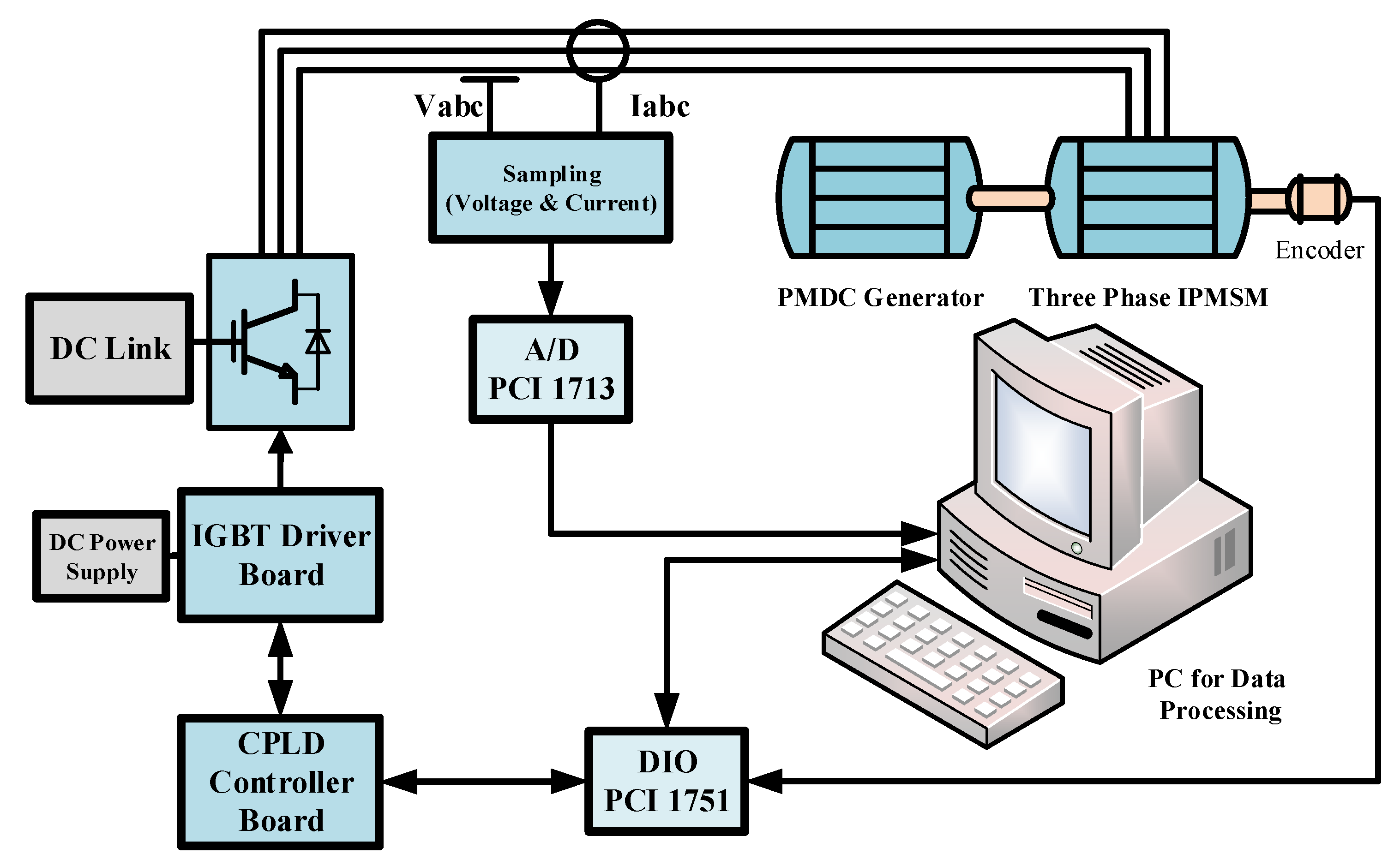
The general block diagram of the suggested nonlinear control system is indicated in Figure 5. To evaluate the results of the proposed control method, an experimental test under real operation conditions is carried out and shown in Figure 6. This setup includes a PC as a motor-drive main processor to monitor the registered waveform; a three-phase SV-PWM inverter and its isolation board to feed the main motor; a measurement board to sample voltage and current vector; a CPLD intermediate board to implement real-time switching patterns utilizing a switching frequency of 5 kHz; a 32 channels converter card of analog to digital (A/D); a 48 bits digital input-output card (DIO) and a permanent magnet DC generator which is connected to the resistive load to stimulate IPMSM load torque.
A digital Advantech PCI-1751 I/O board connects CPLD to the PC as a parallel processor to boost the speed. The following tasks are realized by the CPLD in the experimental setup:
  • Generating the switching pattern of IGBT switches based on the symmetrical SV-PWM technique;
  • Giving a helpful dead time in the so-called switching patterns of power switches;
  • Generating the synchronizing signal for data transmission between the PC and hardware;
  • Shutting down the inverter emergency conditions to stimulate over current or PC hanging states.
Hall-type LEM sensors are used to take a sample of DC-link voltage and stator phase currents. A separate second-order Butterworth low-pass filter is utilized to filter all the measured signals and then a 12-bit PCI A/D card with a sampling rate of up to 100 kS/s is used to convert them to digital signals. A usual brush-type permanent magnet DC generator, connected to the resistance load, is used as the IPMSM load.

3.2.2. Experimental Results

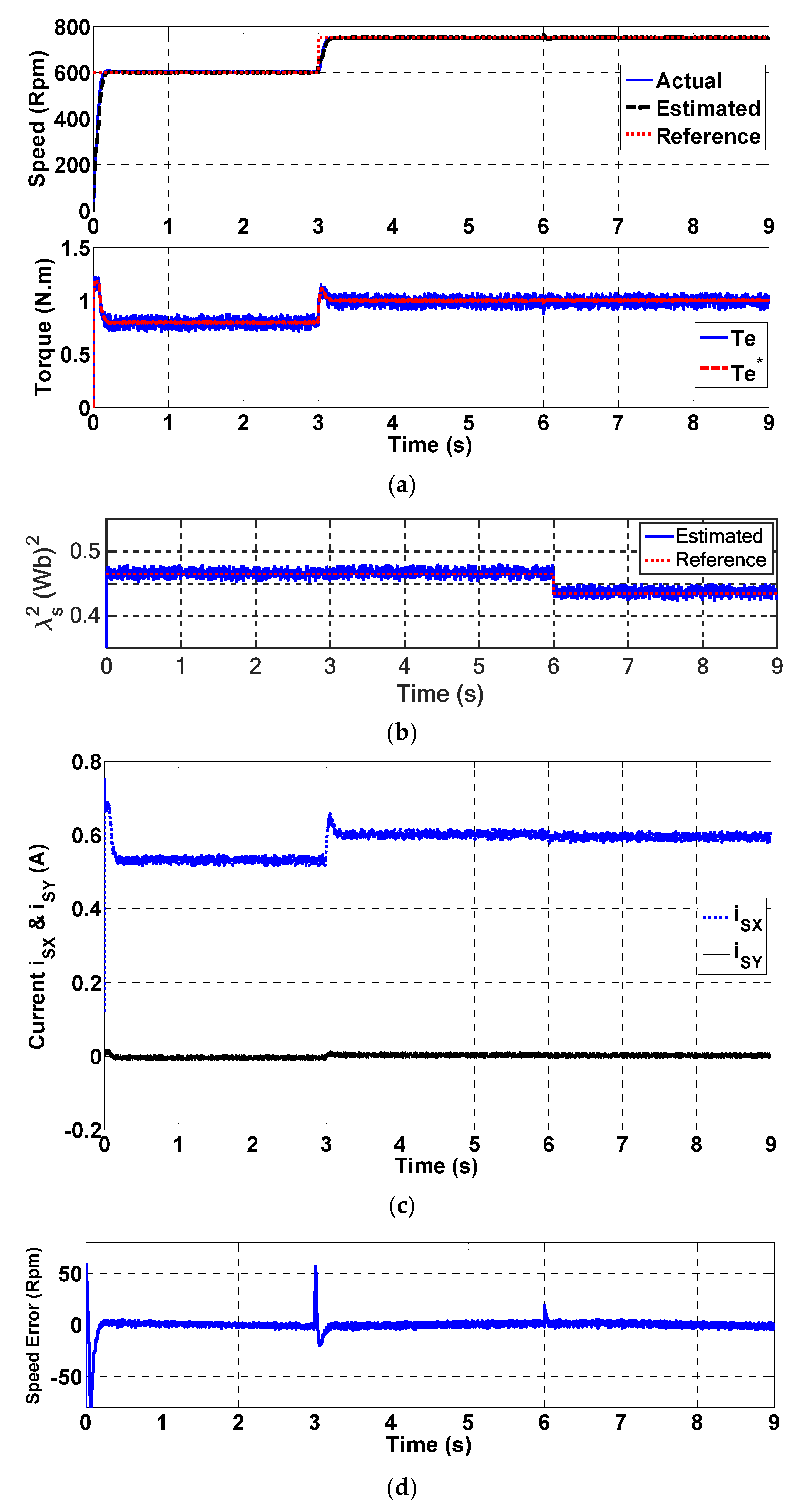
In this section, assuming the magnitude of the squared stator reference flux of λs*2 = 0.465 (Wb)2; stepping up speed reference from zero to 600 rpm at t = 0 s; stepping up to 750 rpm at t = 3 s, and eventually the λs*2 is stepped down from 0.465 (Wb)2 to 0.435 (Wb)2 at t = 6 s. The experimental results for these tests are shown in Figure 7.
Referring to Figure 7, the rotor angular speed, the motor generated electromagnetic torque, and the stator linkage flux variations have followed their corresponding desired reference values very well. It is worth noting that, the only difference between the computer simulation results and the corresponded practical test results is related to the fact that, in the practical test it is not possible to step change the motor parameters and this is only applied in the computer simulation. This is merely to show that the proposed control system is completely independent of the motor real parameter values and even the parameters step changes could not affect the motor performance and stability.
Comparing the experimental results with the related simulation results shown in Figure 4, it can be seen that a good agreement occurs between these two sets of results.

4. Conclusions

In this paper, a new DTC method has been proposed for the IPMSM drive that is developed in the synchronous stator current space vector orientation reference frame (X-Y). In this reference frame, the stator current space vector coincides with the X-axis. The proposed control method is based on sliding mode while assuming the square of the stator flux and motor generated electromagnetic torque as the output variables. Referring to the obtained control law, it is only necessary to know the stator two-axis currents and linkage fluxes for driving the motor. Since the stator currents can be sampled by sensors and the stator linkage fluxes can be easily estimated by the stator voltage equations in the stationary stator two-axis reference frame, the method is purely a parameter independent control technique. In this motor drive, it is no need to know the real value of motor d and q inductances, the rotor permanent magnets linkage fluxes, and even the rotor initial position. In addition, a simple method has been suggested for the estimation of the stator resistance and the rotor angular speed. Some simulation and experimental results have proved the capability and effectiveness of the proposed control method.

Author Contributions

Conceptualization, M.M., J.S., and A.N.-K.; Software, M.M., and A.N.-K.; Su-pervision, M.M., J.S., and M.B.; Validation, M.M., J.S., and M.B.; Writing—Original draft, M.M., J.S., and M.B.; Writing—Review and editing, M.M., J.S., and M.B. All authors have read and agreed to the published version of the manuscript.

Funding

This research received no external funding.

Institutional Review Board Statement

Not applicable.

Informed Consent Statement

Not applicable.

Data Availability Statement

Not applicable.

Conflicts of Interest

The authors declare no conflict of interest.

References

  1. Soleimani, J.; Vahedi, A.; Ejlali, A.; Bafghi, M.B. Study on interior permanent magnet synchronous motors for hybrid electric vehicle traction drive application considering permanent magnet type and temperature. Turk. J. Electr. Eng. Comput. Sci. 2014, 22, 1517–1527. [Google Scholar] [CrossRef]
  2. Ancuti, M.C.; Tutelea, L.; Andreescu, G.D.; Blaabjerg, F.; Lascu, C.; Boldea, I. Practical wide-speed-range sensorless control system for permanent magnet reluctance synchronous motor drives via active flux model. Electr. Power Compon. Syst. 2014, 42, 91–102. [Google Scholar] [CrossRef]
  3. Chen, Y.; Liu, T.H.; Hsiao, C.F.; Lin, C.K. Implementation of adaptive inverse controller for an interior permanent magnet synchronous motor adjustable speed drive system based on predictive current control. IET Electr. Power Appl. 2014, 9, 60–70. [Google Scholar] [CrossRef]
  4. Tang, L.; Zhong, L.; Rahman, M.F.; Hu, Y. A novel direct torque control for interior permanent-magnet synchronous machine drive with low ripple in torque and flux-a speed-sensorless approach. IEEE Trans. Ind. Appl. 2003, 39, 1748–1756. [Google Scholar] [CrossRef]
  5. Inoue, Y.; Morimoto, S.; Sanada, M. Examination and linearization of torque control system for direct torque controlled IPMSM. IEEE Trans. Ind. Appl. 2009, 46, 159–166. [Google Scholar] [CrossRef]
  6. Andreescu, G.D.; Pitic, C.I.; Blaabjerg, F.; Boldea, I. Combined flux observer with signal injection enhancement for wide speed range sensorless direct torque control of IPMSM drives. IEEE Trans. Energy Convers. 2008, 23, 393–402. [Google Scholar] [CrossRef]
  7. Foo, G.; Rahman, M.F. Sensorless direct torque and flux-controlled IPM synchronous motor drive at very low speed without signal injection. IEEE Trans. Ind. Electron. 2009, 57, 395–403. [Google Scholar] [CrossRef]
  8. Lourde, R.M.; Umanand, L.; Rao, N.J. Shaft sensorless vector controlled PMSM servo drive using reduced order speed observer. IETE J. Res. 2000, 46, 77–86. [Google Scholar] [CrossRef]
  9. Zarchi, H.A.; Soltani, J.; Markadeh, G.A. Adaptive input–output feedback-linearization-based torque control of synchronous reluctance motor without mechanical sensor. IEEE Trans. Ind. Electron. 2009, 57, 375–384. [Google Scholar] [CrossRef]
  10. Na, R.; Wang, X.; Cao, Y.; Mao, L. Adaptive Input-Output Feedback Linearization control for IPMSM using Maximum Torque per Ampere strategy. In Proceedings of the 2011 6th International Forum on Strategic Technology, Harbin, China, 22–24 August 2011; Volume 2, pp. 684–689. [Google Scholar]
  11. Lin, C.K.; Liu, T.H.; Yang, S.H. Nonlinear position controller design with input–output linearisation technique for an interior permanent magnet synchronous motor control system. IET Power Electron. 2008, 1, 14–26. [Google Scholar] [CrossRef]
  12. Vittek, J.; Dodds, S.J.; Bris, P.; Stulrajter, M.; Makys, P. Experimental verification of chattering free sliding mode control of the drive position employing PMSM. J. Electr. Eng. -Bratisl. 2008, 59, 139. [Google Scholar]
  13. Ahmed, M.; Karim, F.M.; Abdelkader, M.; Abdelber, B. Input output linearization and sliding mode control of a permanent magnet synchronous machine fed by a three levels inverter. J. Electr. Eng. 2006, 57, 205–210. [Google Scholar]
  14. Fang, C.H.; Huang, C.M.; Lin, S.K. Adaptive sliding-mode torque control of a PM synchronous motor. IEE Proc. -Electr. Power Appl. 2002, 149, 228–236. [Google Scholar] [CrossRef]
  15. Mishra, J.; Wang, L.; Zhu, Y.; Yu, X.; Jalili, M. A Novel Mixed Cascade Finite-Time Switching Control Design for Induction Motor. IEEE Trans. Ind. Electron. 2019, 66, 1172–1181. [Google Scholar] [CrossRef]
  16. Wang, L.; Mishra, J.; Zhu, Y.; Yu, X. An Improved Sliding-Mode Current Control of Induction Machine in Presence of Voltage Constraints. IEEE Trans. Ind. Inform. 2020, 16, 1182–1191. [Google Scholar] [CrossRef]
  17. Kaynak, O.; Erbatur, K.; Ertugnrl, M. The fusion of computationally intelligent methodologies and sliding-mode control-a survey. IEEE Trans. Ind. Electron. 2001, 48, 4–17. [Google Scholar] [CrossRef]
  18. Feng, Y.; Yu, X.; Han, F. High-order terminal sliding-mode observer for parameter estimation of a permanent-magnet synchronous motor. IEEE Trans. Ind. Electron. 2012, 60, 4272–4280. [Google Scholar] [CrossRef]
  19. Wang, G.; Li, Z.; Zhang, G.; Yu, Y.; Xu, D. Quadrature PLL-based high-order sliding-mode observer for IPMSM sensorless control with online MTPA control strategy. IEEE Trans. Energy Convers. 2012, 28, 214–224. [Google Scholar] [CrossRef]
  20. Uddin, M.N.; Rebeiro, R.S. Online efficiency optimization of a fuzzy-logic-controller-based IPMSM drive. IEEE Trans. Ind. Appl. 2010, 47, 1043–1050. [Google Scholar] [CrossRef]
  21. Lee, Y.; Sul, S.K. Model-based sensorless control of an IPMSM with enhanced robustness against load disturbances based on position and speed estimator using a speed error. IEEE Trans. Ind. Appl. 2017, 54, 1448–1459. [Google Scholar] [CrossRef]
  22. Lin, F.J.; Liu, Y.T.; Yu, W.A. Power perturbation based MTPA with an online tuning speed controller for an IPMSM drive system. IEEE Trans. Ind. Electron. 2017, 65, 3677–3687. [Google Scholar] [CrossRef]
  23. Wu, X.; Huang, S.; Liu, K.; Lu, K.; Hu, Y.; Pan, W.; Peng, X. Enhanced position sensorless control using bilinear recursive least squares adaptive filter for interior permanent magnet synchronous motor. IEEE Trans. Power Electron. 2019, 35, 681–698. [Google Scholar] [CrossRef]
  24. Messali, A.; Hamida, M.A.; Ghanes, M.; Koteich, M. Estimation Procedure Based on Less Filtering and Robust Tracking for a Self-Sensing Control of IPMSM. IEEE Trans. Ind. Electron. 2020, 68, 2865–2875. [Google Scholar] [CrossRef]
  25. Najjar-Khodabakhsh, A.; Soltani, J. MTPA control of mechanical sensorless IPMSM based on adaptive nonlinear control. ISA Trans. 2016, 61, 348–356. [Google Scholar] [CrossRef] [PubMed]
  26. Najjar-Khodabakhsh, A.; Soltani, J. Implementation of sensorless IPMSM drive using the stator current space vector orientation reference frame. COMPEL Int. J. Comput. Math. Electr. Electron. Eng. 2016, 35, 1237–1256. [Google Scholar] [CrossRef]
  27. Moradian, M.; Soltani, J.; Najjar-Khodabakhsh, A.; Markadeh, G.A. Adaptive torque and flux control of sensorless IPMSM drive in the stator flux field oriented reference frame. IEEE Trans. Ind. Inform. 2018, 15, 205–212. [Google Scholar] [CrossRef]
  28. Park, D.M.; Kim, K.H. Parameter-independent online compensation scheme for dead time and inverter nonlinearity in IPMSM drive through waveform analysis. IEEE Trans. Ind. Electron. 2013, 61, 701–707. [Google Scholar] [CrossRef]
  29. Vas, P. Sensorless Vector and Direct Torque Control; Oxford University Press: Oxford, UK, 1998. [Google Scholar]
  30. Marino, R.; Tomei, P. Nonlinear Control Design: Geometric; Adaptive and Robust; Prentice Hall International (UK) Limited: London, UK, 1995. [Google Scholar]
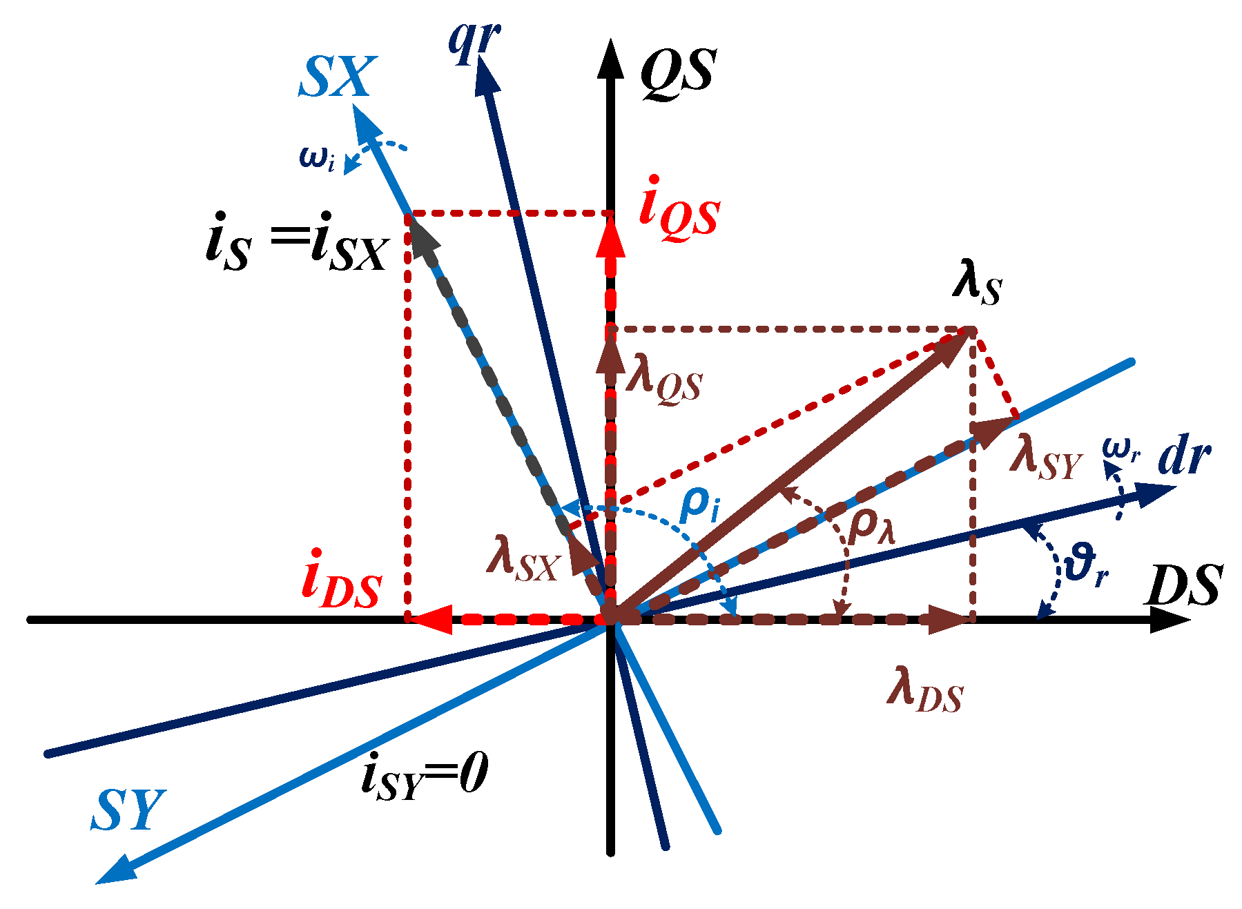
Figure 1. Relationship of spatial (X-Y) and stationary (DS-QS) reference frames.
Energies 14 02365 g001
Figure 2. Rotor speed estimation.
Energies 14 02365 g002
Figure 3. PI resistance estimator.
Energies 14 02365 g003
Figure 4. Simulation results of IPMSM drive: (a) torque and speed, (b) squared of stator flux, (c) X- and Y-axis components of stator fluxes and currents.
Energies 14 02365 g004aEnergies 14 02365 g004b
Figure 5. Block diagram of proposed IPMSM drive system control.
Energies 14 02365 g005
Figure 6. Laboratory implementation block diagram.
Energies 14 02365 g006
Figure 7. Experimental results of IPMSM drive: (a) torque and speed, (b) square of stator flux, (c) X- and Y-axis component currents, (d) error of speed.
Energies 14 02365 g007
Table 1. Parameters of the IPMSM.
P (Pole Pairs)2
rs21.5 Ω
λm0.493 Wb
Ld0.3 H
Lq0.8 H
Pn300 W
Is1.1 A
f50 Hz
Table 2. Gains of control system.
PI (Speed Controller)KP = 0.05KI = 0.15
Positive constantK1 = 375K2 = 890
SMC positive control gainsλ1 = 1.55λ2= 1.55
Publisher’s Note: MDPI stays neutral with regard to jurisdictional claims in published maps and institutional affiliations.