Abstract
The operational reliability and high efficiency of modern electrical machines depend on the ability to transfer heat in the construction parts of the machine. Therefore, many authors study various thermal models and work on the development of effective heat dissipation. New insights and methods lead to improved techniques for the thermal design of electrical machines. This paper presents an experimentally validated thermal model of a permanent magnet synchronous motor (PMSM) with an improved slot winding model. It also deals with various approaches to homogenization and equivalent material properties of a tooth-coil winding sub-model. First, an algorithm for building a lumped-parameter thermal network (LPTN) of PMSM is described and its properties and problems are discussed. Subsequently, a sub-model of a slot with a winding based on the finite element method (FEM) is introduced. This sub-model is able to generate different conductor distributions based on probabilistic methods for a specified fill factor. This allows the verification of various homogenization approaches and at the same time it is a tool that automatically calculates thermal resistances for the LPTN.
1. Introduction
Today, especially with regard to climate challenges, higher energy efficiency and power density of electrical machines are required. This fact brings new challenges in the design of an electrical motor especially for traction applications and electric vehicles (EV). In this day, new types or modified designs of electrical machines are widely analyzed and researched. One of the most utilized types of electrical motors in the automotive industry is a permanent magnet synchronous motor (PMSM). In recent years, research and development of PMSM for automotive electric traction machines have greatly intensified [1,2,3,4]. One of the commonly used construction typologies of PMSM in the automotive industry is a machine with tooth-coil winding or a machine with concentrated winding. This brings the advantage of low-cost production, high torque density and high efficiency [5,6,7]. On the other hand, the manufacturing process brings new challenges to the thermal design of a PMSM [8]. Randomly wound windings mean great uncertainties and the manufactured winding can thus differ significantly from the winding modeled by conventional methods.
The current technical literature divides electric motor thermal analysis and design into two main categories [9]: the thermal design and analyses based on the numerical methods and those based on analytical methods [10,11]. The numerical methods include the finite element method (FEM) and computational fluid dynamics (CFD). These methods allow detailed modeling of any machine geometry and the prediction of thermal flow in individual parts of the machine [12,13,14]. However, both of these numerical methods are very demanding in the model setup and computational time. Accurate homogenization of the individual motor parts or methods such as model order reduction and cluster computing are then necessary to reduce the computing time [15,16].
An analytical method suitable for the thermal modeling of the electrical machines is the lumped-parameter thermal network (LPTN). The thermal network is based on the machine dimensions and principles of thermal exchange [17,18]. One of the unresolved issues of the LPTN approach is the thermal model of the stator winding [16,17,18,19,20]. The first problem is that the area of the winding in the slot contains several materials with orders of magnitude different thermal conductivity values. The second problem is that for random-wound windings, it is impossible to determine the exact positions of the conductors in the slot [5]. These facts do not allow simple homogenization of the region. Figure 1 shows the differences in the conductor distribution in the slot of one synchronous machine.
Most commonly used methods for modeling of winding slot region are:
- Equivalent insulation—This method considers the conductors (copper) located in the middle of the slot region. The insulation and impregnation materials together with the air are modeled as an equivalent insulating material that fills the space around the conductors [16].
- Layer winding method—This method divides the slot region into several layers of copper and insulation and the model is then able to predict the distribution of temperature in these layers. The temperature of conductors then depends on the positions of the layers [21,22].
- Cuboidal method—Here, the thermal model of the slot region is based on the cuboidal winding. This method also allows the heat transfer of the winding region into the third (axial) dimension [23].
- Homogenization method—This method is based on the equivalent thermal conductivity derived from dimensions and material parameters of the slot winding region as a serial connection of the thermal resistances of each material in the slot [10,20].

Figure 1.
Stator slots in the cut synchronous machine.
Figure 1.
Stator slots in the cut synchronous machine.

All previously mentioned methods depend on several factors, such as the conductivity of each material, the dimensions of the slot region, the dimensions and the shape of the conductors and the slot fill factor. The fill factor is the ratio between the area of the conductors and the slot area. A higher fill factor means a higher power density of the electrical machine and a better thermal dissipation from the slot area. For various winding types, the slot fill factor ranges from 40% to 85%. The simplest winding types are characterized by round conductors, a random-wound winding process with great uncertainties, low manufacturing requirements and therefore low cost. These types are suitable for mass production, but they have a lower fill factor around 40% [24]. This is the main reason why they are used for the high-power traction machines with lower fill factors. These machines require high efficiency, high power density and low-cost manufacturing [25,26,27]. Another tooth-coil winding type with round conductors is compressed winding. Thanks to the high packing density of conductors, this winding type achieves a higher fill factor approximately 65% [24]. The winding with the highest fill factor is layer winding, where the conductors are uniformly arranged in layers [28].
The main goal of this paper is to investigate the homogenization and estimation of the equivalent material properties of the sub-model of the tooth-coil winding. As mentioned above this is currently one of the main topics discussed in the thermal modeling of an electrical machines. Our approach uniquely combines LPTN and FE models, achieving an error of less than 5% compared to the measurement. The LPTN model is fast, modular and allows easy redefinition and addition of individual parts for new machine topologies. In order to increase the accuracy of the winding temperature calculation, the FE model of the slot with winding is presented. This model is based on a random conductor generator that simulates the actual process of manufacturing of randomly wound windings. The FE model calculates the thermal resistances for the LPTN model and further allows a more accurate calculation of temperature distribution after the boundary conditions are known from the LPTN model. Our hybrid model is then verified by measuring temperatures on a traction high-speed synchronous motor.
An important parameter that is mentioned throughout the text is the equivalent thermal conductivity . This parameter expresses in one number the thermal conductivity of a certain part of the machine. There are several possible methods for calculating this conductivity and they are presented in the following sections.
The work presented in this paper is organized into six chapters. A flowchart of the research is shown in Figure 2 and it also corresponds to the paper’s structure. Each chapter is focused on the investigation and description of the individual part of a main topic. Section 1 describes the state-of-the-art thermal modeling of electrical machines; this section also defines the main research problem in thermal modeling and presents the goal of this paper. Section 2 describes the software algorithm of the modular thermal model of the PMSM. Section 3 presents the algorithm of the finite element methods with a random conductor distribution generator and also shows the relation between slot fill factor and the range of thermal resistances of the winding. Section 4 shows experimental validation of calculated results for various methods for estimating equivalent thermal resistances presented in Section 2 and Section 3. Discussion of results obtained by measurement and presented thermal models is presented in Section 5. Investigated results are summarized in Section 6.
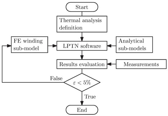
Figure 2.
Flowchart of the thermal analysis.
2. Software Algorithmization of Thermal Modeling
When designing a machine, it is necessary to quickly assess various thermal designs, and LPTN models can serve well for this. To be as efficient as possible, the model should automatically generate a thermal network based on the input parameters. Furthermore, it is necessary to be able to implement new machine topologies and new research results into the model as easily as possible. This is achieved through the concept of sub-models, which divide the electrical motor into individual layers from shaft to housing. These layers are shown in Figure 3. This model also allows extended, more accurate thermal calculations of individual sub-models after the global model is calculated and the temperatures of the surrounding components are known. The software is built to be as clear as possible for the user and there is also a possibility to connect the results of electromagnetic design procedure to the input file. The software is currently limited to steady-state analysis of a PMSM with standard rotor and radial magnetic flux. The calculation procedure is shown in Figure 4.
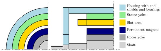
Figure 3.
Thermal layers of a PMSM.
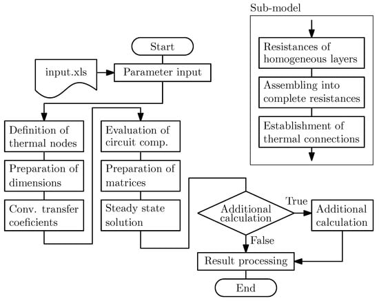
Figure 4.
Flowchart of LPTN-based software.
First, all necessary data are set or loaded, such as the lengths of discretization elements, dimensions of machine parts, ambient temperatures, etc. In the next step the number of a nodes per component is set, based on the length of the elements and dimensions of the component. Next the global thermal network is defined, which requires an estimation of the convection heat transfer coefficients. When this is done, the sub-models are defined. The sub-model creation is shown in Figure 4. For each homogeneous layer, thermal resistances are calculated from input parameters and thermal connections are established. Finally, a global matrix is assembled, the vector of heat losses for individual nodes is set and steady-state analysis can be computed. If necessary, further calculations are performed and all resulting temperatures are processed into a result table.
2.1. Lumped Thermal Models of Winding
As already mentioned, the winding is one of the parts of the machine that is very problematic from the point of view of thermal modeling. Due to uncertain distribution of conductors in the slot and imperfect impregnation, which leaves air cavities with poor thermal conductivity, it is very difficult to correctly predict the thermal distribution of the winding by analytical methods. In our software the general winding is modeled as the element shown in Figure 5, where are thermal resistances in the axial direction, are resistances in the radial direction towards the yoke and towards the air gap and is the tangential resistance towards the stator tooth.
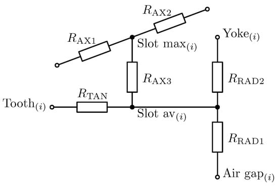
Figure 5.
Slot thermal network.
In the axial direction, only the area of copper, which can be easily analytically described, is used to determine the resistance. However, it is difficult to determine the resistances in the radial and tangential direction, for which separate models are required for each type of winding. For windings with rectangular conductors the analytical model is quite accurate because positions of conductors and layers of insulation are known. For this reason, it is possible to create a detailed thermal network with a node in each conductor. From its solution the maximum temperature and the heat flow in each direction can be determined. The temperature difference and heat flux are then used to calculate the thermal resistances shown in Figure 5, using (1), where is maximal temperature in the slot, is boundary temperature on the side of the slot and Q is heat flux through the side of the slot. This detailed model can be used again for the estimation of the temperatures of conductors after the whole model is solved and the boundary conditions are known. However, this procedure is not possible for random-wound windings where the positions of the conductors are not clearly defined [5].
3. Finite Element Method
In order to solve this problem, the following Matlab code based on the 2D FEM was developed. To ensure that the calculation is as fast as possible, it is convenient to vectorize most of the operations. Vectorized assembly of stiffness and mass matrices is done using the code of the authors [29]. To generate the triangular mesh, the third-party code from [30] is used. The result of the calculation of the temperature of the slot using this code is shown in Figure 6.
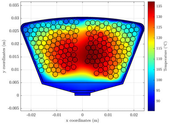
Figure 6.
Temperature distribution in the slot.
3.1. Slot-Filling Algorithm
An important part of the code is the function that fills the slot with conductors. The inputs are the dimensions of the slot, the radius of the conductors and their number N, or the required fill factor . The function then returns a vector of the conductor centers. The filling loop can end in three ways: (1) the required number of conductors is reached; (2) the required fill factor is reached; (3) there is no space left for another conductor.
The first step is that the algorithm divides the usable area of the slot by a rectangular mesh, which can theoretically be infinitely dense, but the more points it has, the slower the calculations are. Its density is thus derived from the radius of the conductor so that the filling is relatively fast and at the same time the main aspect of the code, the probability-driven random selection of the centers, is not too limited. The filling loop is described in detail in Figure 7.
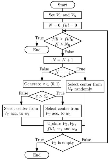
Figure 7.
Flowchart of slot-filling function.
The selection of the conductor centers is controlled by four main variables: two logical vectors and , which contain points of the mesh belonging to two respective regions and the weights and . Vector contains points that are excluded from the selection of new centers, while vector contains points from which new centers are selected. The vector initially contains only a strip of points at the bottom of the slot. As more conductors are added, these vectors are updated.
The new centers are not selected from the vector randomly, but according to the weights and , these weights correspond to the probabilities of selection of a given point. The weight is a projection of the function on the points of the rectangular mesh. This function has a maximum at the point of closest to the bottom of the slot. The weight is then similarly a projection of the function on the mesh, but this time the function is a paraboloid with a maximum at the nearest point of the vector to the mass center of the conductors. The functions and are shown in Figure 8, this geometry corresponds to the L-type slot (Figure 9c). The orange-bounded region is , the red dot is then the closest point of the to the center of mass, which is located between the three conductors.
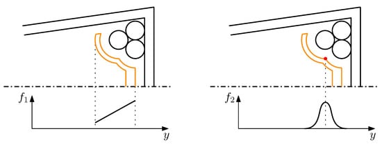
Figure 8.
Weight functions for selection of new center.
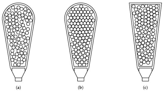
Figure 9.
Examples of filled slots. (a) , (b) , (c) L-type slot
Whether the new center will be selected according to the weight or is then controlled by the user specified parameter , which controls the density of the conductors in the slot. For the new center is always selected according to , for the chance is 50% for each and for the new center is always selected according to and the resulting distribution then corresponds to hexagonal packing with slight adjustable deviations. Two extreme cases are shown in Figure 9a,b. Filling of this slot takes approximately , while the size of the vectors and is 27,861 points, if we choose a denser mesh, then for 112,169 points the slot is filled in approximately .
3.2. Homogenization
If we are mainly interested in the maximum temperature of the slot rather than its distribution, it may seem that homogenization is a useful tool. Its various forms, advantages and limits have already been explored by many authors, for example: [31,32]. If we compare the results from the FE simulation with conductors and the simulation with homogenization for different fill factors, while keeping the same Ampere-turn value, we get the results depicted in Figure 10 and Figure 11. These figures show the maximum slot temperatures from which the lowest maximum temperature of the whole set was subtracted for better comparison. Each of the two figures shows 5000 temperatures calculated for randomly generated conductor distributions.
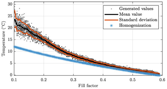
Figure 10.
Maximum temperatures of L-type slot.
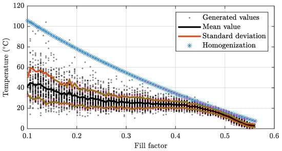
Figure 11.
Maximum temperatures of slot for concentric winding.
The formula used to calculate homogenization is Equation (2). Where is the fill factor (ratio between the area of conductors and the slot area), is thermal conductivity of the surrounding material and is thermal conductivity of the copper conductors.
These temperatures were calculated for slots designed with a fill factor of approximately , so as the fill decreases below this value, the current density increases to unrealistic values. However, this does not change the fact that the variance of the maximum temperatures increases significantly with a smaller fill factor. In the case of the L-type slot, the results of the simulation with the conductors and simulation with the homogenization start to correspond approximately from a fill factor of . The homogenization then approximates the best case, i.e., the conductors are arranged so that the maximum temperature is the lowest of all the possible arrangements. The behavior of homogenization for the slot with concentrated winding is different, here the homogenization from a fill factor of approximate the worst case of the arrangement of the conductors.
This difference in behavior is due to the fact that while in the L-type slot all the conductors are close to each other, in the slot with the concentrated winding the conductors are wound around the stator tooth and as a result there are two clusters of conductors separated by a gap.
Although homogenization can save computational time, it can be used only in cases where we are sure it matches a more accurate model with the conductors. However, this region of trust depends on several factors and will be the subject of further research. Homogenization is nevertheless used in the code to homogenize the conductor material with its thin insulating layer, which could be otherwise considered in the problem only with the use of an extremely dense mesh.
3.3. Thermal Resistances
An important function of this FE-based model is to determine the thermal resistances for the LPTN model. These resistances are calculated using (1) and the flux is then calculated from the temperature distribution according to Fourier’s law (3), where k is thermal conductivity, is temperature gradient and S is a closed surface. Subsequently, the slot can be artificially divided into four parts: upper, lower, left and right, each of which passes through a part of the heat flow Q. This sub-model definition is then used in LPTN model instead of the common sub-model mentioned in Section 2.1. These thermal resistances are shown in Figure 12.
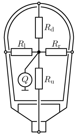
Figure 12.
Slot thermal resistances for four directions.
The following Figure 13, Figure 14 and Figure 15 show the dependencies of the individual thermal resistances on the fill factor. For all resistances, a similar trend can also be seen for the temperature distribution (Figure 10 and Figure 11), i.e., that with lower fill factors the variance of resistances increases. The strongest dependence of mean value and fill factor can be seen in case of the resistance —the resistance between the hot-spot and the edge of the slot adjacent to the air gap.
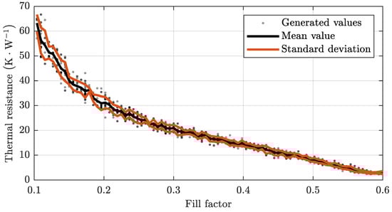
Figure 13.
Thermal resistance .
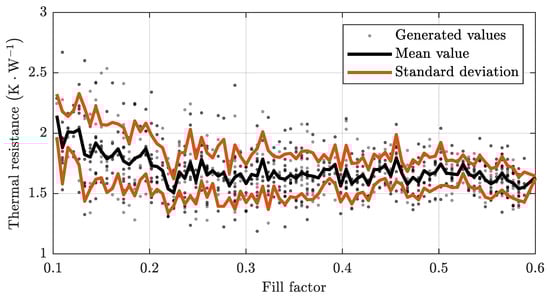
Figure 14.
Thermal resistance .
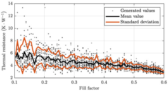
Figure 15.
Thermal resistances , .
For resistance , connecting the hot-spot and the edge of the slot adjacent to the stator yoke, the dependence is relatively low. An almost linear decrease of mean value of thermal resistance with fill factor can be observed for the resistances and , which connect the hot-spot with the edges of the slot at the left and right of the stator teeth. All these values have been calculated for a slot with a concentrated winding shown in Figure 6 and the variance of values and mean curves will be different for each type of winding and slot geometry.
4. Experimental Validation and Measurement
To test the hybrid thermal model, we chose a traction high-speed synchronous motor with surface mounted permanent magnets on the rotor and with a randomly wound stator winding. We entered the parameters of this machine into the model and performed a thermal analysis and then measured the machine temperatures using thermo-couples. We also calculate the equivalent thermal conductivities from the machine measurements and then compare them with the calculation of the equivalent thermal conductivities calculated using conventional homogenization methods. The tested PMSM is used together with the gearbox as a compact traction machine with speed range of 3–10 kRPM. The main parameters of the motor are presented in Table 1.

Table 1.
Main parameters of the measured machine.
To make the thermal measurements as complex as possible, the machine was tested as a motor, a generator and as a stand-alone machine with its rotor removed. During the tests, the stator winding was supplied with direct current corresponding to RMS value of rated current (see Table 1) and one phase was measured. Motor was tested with a load according to duty cycle S1-continuously loaded. The thermo-couples, PT100 in four wire connections, were placed in and around the loaded phase, in several stator tooth positions and in the stator yoke to reduce noise including the shift noise. For measuring ALMEMO 5690-2M combined with ALMEMO 8690-9A were utilized. In order to accurately determine the temperature distribution in the machine, altogether 40 temperatures were continuously measured. Figure 16 shows the model of machine with some of the thermo-couples’ positions marked and the Figure 17 then shows the real machine during the measurements.
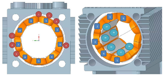
Figure 16.
Position of the thermo-couples in the model.
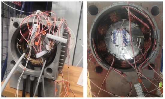
Figure 17.
Thermo-couples in the machine.
From these measurements it is then possible to calculate the thermal conductivities of the contact surfaces between the winding and the stator of the machine. These conductivities are calculated using (4), where l is the middle distance from the center of the slot to the contact surface, A is the area of the contact surface (area of the yoke and the area of both stator teeth) and is thermal resistance. These thermal conductivities are calculated for the two measured (highest 61 °C and lowest 54 °C) temperature differences between the winding in the slot and the stator tooth. Temperature differences were measured in a steady state.
These temperature differences are then considered in the calculation of the thermal resistances according to Equation (5), where is the temperature difference and are Joule losses for rated current, in our case . The tested machine had a star-connected winding without an achievable zero node and the winding was connected in series-parallel during the tests.
Figure 18 shows the transient of 40 measured temperatures, temperatures of end winding and slot winding of loaded phase are highlighted, other values are plotted as a range of temperatures. First, the machine was powered by DC current and heated by Joule losses without a rotor. The second test was performed with the rotor inside. There was no significant difference between the measured temperatures in both cases, and it can be said that the thermal properties of the air gap are the same with or without the rotor. For the two mentioned thermal differences, the thermal conductivities are: 0.448 W·m·K for 61 °C difference and 0.505 W·m·K for 54 °C difference.
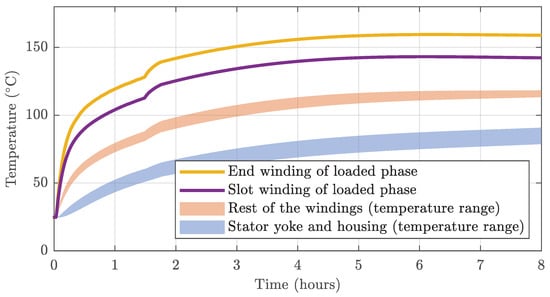
Figure 18.
Temperature transient.
5. Comparison of Measured Results and Homogenization Methods
The measured thermal conductivities will now be compared with several examples of methods for calculation equivalent thermal conductivities used in the literature. Each result is calculated with the same dimensions and parameters of the machine. The first Equation (6) is based on the comparison of areas of individual materials in the slot. is the total area of the slot, is area of the conductors, is the area of the insulation and is the area of the impregnation. Then , and are the thermal conductivities of these materials. The equivalent thermal conductivity is in this case 0.365 W·m·K.
The next Equation (7) was already presented is Section 3.2 and it is one of the most commonly used equations for homogenization. The individual parameters then have the same meaning as in the previous equation. If we want a more accurate calculation, it is possible to use the same calculation once more and calculate the equivalent thermal conductivity using the thermal conductivities of copper and its thin insulation. The result of this equation is 0.512 W·m· K.
The next Equation (8) from [24] considers the impregnation as another insulating layer of the winding. is conductor radius and is the thickness of the conductor insulation. The equivalent thermal conductivity is in this case 0.693 W·m·K.
There are many other equations and variations on these mentioned equations in the literature, but the results are then very similar. Let us now compare the measured results and the results of the LPTN model with different sub-modules for calculating the thermal resistances between the winding and the stator.
All results are compared in Table 2. The average temperature measured for a given component is always used to calculate the percentage error. The column labeled is the result of the LPTN model, into which the average equivalent thermal conductivity 0.47 W·m·K derived from machine measurements is used. The column is then the result of the LPTN model using the equivalent conductivity of 0.512 W·m·K, calculated using (7), which has the smallest error of all the formulas mentioned. However, both of these calculations have an error over 10% for the temperatures of the slot winding and end winding.
Table 2.
Comparison of results.
The calculation using thermal resistances generated for a given slot dimensions and the fill factor using the FE model has the smallest error (below 5%). In addition, after calculating the LPTN model, it allows to set the calculated temperatures as the boundary conditions and thus determine more precisely the temperature distribution in the slot, the position of the hot-spot and its approximate temperature.
6. Conclusions
This paper presents a new approach for determining the thermal resistances or equivalent thermal conductivities of stator slot winding. This novel method is based on a unique combination of most commonly used methods these days: LPTN and FE/CFD. The developed modular LPTN model enables fast temperature calculations in an electrical machine using a network of thermal resistors. The modularity of this model then makes it easy to redefine and add individual parts for new machine topologies. This is an important tool in the thermal design of an electrical machine, the designer can always quickly check how design changes will affect the temperatures in the machine. The FE model is used as a sub-model for accurate calculations of the thermal resistances of the slot with winding. This model is able to generate random distributions of conductors in a slot, which simulates the actual process of manufacturing of randomly wound winding. Furthermore, this model can be used to more accurately determine the temperature distribution in the slot after the boundary conditions are known from the LPTN model solution. The newly designed and implemented method allows fast thermal analyses with a high accuracy of results. The combination of these methods then achieves a margin of error below 5% compared to measurements of the temperature on a real machine. The findings from the series of measurements will be further used to further improve the software.
Author Contributions
Methodology, Concept, R.P.; Software, J.K. and M.S.; Validation, Measurements, L.V. and M.S.; Writing, R.P., J.K., L.V. and M.S.; Supervision, R.P. All authors have read and agreed to the published version of the manuscript.
Funding
This research has been supported by the Ministry of Education, Youth and Sports of the Czech Republic under the RICE New Technologies and Concepts for Smart Industrial Systems, project No. LO1607 and by an internal project SGS-2018-043.
Conflicts of Interest
The authors declare no conflict of interest.
References
- De Santiago, J.; Bernhoff, H.; Ekergård, B.; Eriksson, S.; Ferhatovic, S.; Waters, R.; Leijon, M. Electrical motor drivelines in commercial all-electric vehicles: A review. IEEE Trans. Veh. Technol. 2012, 61, 475–484. [Google Scholar] [CrossRef]
- Chin, J.-W.; Cha, K.-S.; Park, M.-R.; Park, S.-H.; Lee, E.-C.; Lim, M.-S. High Efficiency PMSM with High Slot Fill Factor Coil for Heavy-Duty EV Traction Considering AC Resistance. IEEE Trans. Energy Convers. 2020. [Google Scholar] [CrossRef]
- Zhao, W.; Lipo, T.A.; Kwon, B. Comparative Study on Novel Dual Stator Radial Flux and Axial Flux Permanent Magnet Motors With Ferrite Magnets for Traction Application. IEEE Trans. Magn. 2014, 50, 1–4. [Google Scholar] [CrossRef]
- Laskaris, K.I.; Chaniotis, A.; Kladas, A.G. High performance traction motor design and construction for small passenger electric car. In Proceedings of the XIX International Conference on Electrical Machines-ICEM 2010, Rome, Italy, 6–8 September 2010; pp. 1–6. [Google Scholar]
- Acquaviva, A.; Skoog, S.; Grunditz, E.; Thiringer, T. Electromagnetic and Calorimetric Validation of a Direct Oil Cooled Tooth Coil Winding PM Machine for Traction Application. Energies 2020, 13, 3339. [Google Scholar] [CrossRef]
- El-Refaie, A.M. Fractional-slot concentrated-windings synchronous permanent magnet machines: Opportunities and challenges. IEEE Trans. Ind. Electron. 2010, 57, 107–121. [Google Scholar] [CrossRef]
- Gai, Y.; Kimiabeigi, M.; Chuan Chong, Y.; Widmer, J.D.; Deng, X.; Popescu, M.; Goss, J.; Staton, D.A.; Steven, A. Cooling of Automotive Traction Motors: Schemes, Examples, and Computation Methods. IEEE Trans. Ind. Electron. 2019, 66, 1681–1692. [Google Scholar] [CrossRef]
- Liu, C.; Xu, Z.; Gerada, D.; Li, J.; Gerada, C.; Chong, Y.C.; Zhang, H. Experimental investigation on oil spray cooling with hairpin windings. IEEE Trans. Ind. Electron. 2019, 67, 7343–7353. [Google Scholar] [CrossRef]
- Rosu, M.; Zhou, P.; Lin, D.; Ionel, D.M.; Popescu, M.; Blaabjerg, F.; Staton, D. Multiphysics Simulation by Design for Electrical Machines, Power Electronics and Drives; John Wiley & Sons: New York, NY, USA, 2017; pp. 291–295. [Google Scholar]
- Nonneman, J.; T’Jollyn, I.; Sergeant, P.; De Paepe, M. Quality Assessment of a 2D FE Based Lumped Parameter Electric Motor Thermal Model Using 3D FE Models. Int. Conf. Electr. Mach. (ICEM) 2020, 1, 973–980. [Google Scholar]
- Ghahfarokhi, P.S.; Kallaste, A.; Vaimann, T.; Belahcen, A. Thermal analysis of totally enclosed fan cooled synchronous reluctance motor-state of art. In Proceedings of the IECON 2019-45th Annual Conference of the IEEE Industrial Electronics Society, Lisbon, Portugal, 14–17 October 2019; Volume 1, pp. 4372–4377. [Google Scholar]
- Tosetti, M.; Maggiore, P.; Cavagnino, A.; Vaschetto, S. Conjugate heat transfer analysis of integrated brushless generators for more electric engines. IEEE Trans. Ind. Appl. 2014, 50, 2467–2475. [Google Scholar] [CrossRef]
- Baker, J.L.; Wrobel, R.; Drury, D.; Mellor, P.H. A methodology for predicting the thermal behaviour of modular-wound electrical machines. In Proceedings of the 2014 IEEE Energy Conversion Congress and Exposition (ECCE), Pittsburgh, PA, USA, 14–18 September 2014; pp. 5176–5183. [Google Scholar]
- Boglietti, A.; Carpaneto, E.; Cossale, M.; Vaschetto, S. Stator-Winding Thermal Models for Short-Time Thermal Transients: Definition and Validation. IEEE Trans. Ind. Electron. 2016, 63, 2713–2721. [Google Scholar] [CrossRef]
- Boglietti, A.; Cossale, M.; Popescu, M.; Staton, D.A. Electrical machines thermal model: Advanced calibration techniques. IEEE Trans. Ind. Appl. 2019, 55, 2620–2628. [Google Scholar] [CrossRef]
- Boglietti, A.; Carpaneto, E.; Cossale, M.; Popescu, M.; Staton, D.; Vaschetto, S. Equivalent thermal conductivity determination of winding insulation system by fast experimental approach. In Proceedings of the 2015 IEEE International Electric Machines & Drives Conference (IEMDC), Coeur d’Alene, ID, USA, 10–13 May 2015; pp. 1215–1220. [Google Scholar]
- Lee, J.; Yeo, H.; Jung, H.; Kim, T.; Ro, J. Electromagnetic and thermal analysis and design of a novel-structured surface-mounted permanent magnet motor with high-power-density. IET Electr. Power Appl. 2019, 13, 472–478. [Google Scholar] [CrossRef]
- Fan, J.; Zhang, C.; Wang, Z.; Dong, Y.; Nino, C.E.; Tariq, A.R.; Strangas, E.G. Thermal analysis of permanent magnet motor for the electric vehicle application considering driving duty cycle. IEEE Trans. Magn. 2010, 46, 2493–2496. [Google Scholar] [CrossRef]
- Wrobel, R.; Ayat, S.; Godbehere, J. A systematic experimental approach in deriving stator-winding heat transfer. In Proceedings of the IEEE International Electric Machines and Drives Conference (IEMDC), Miami, FL, USA, 21–24 May 2017; pp. 1–8. [Google Scholar]
- Romanazzi, P.; Ayat, S.; Wrobel, R.; Howey, D.A. 3D homogenisation of concentrated windings with rectangular conductors. In Proceedings of the IEEE International Electric Machines and Drives Conference (IEMDC), Miami, FL, USA, 21–24 May 2017; pp. 1–8. [Google Scholar]
- Staton, D.; Boglietti, A.; Cavagnino, A. Solving the More Difficult Aspects of Electric Motor Thermal Analysis in Small and Medium Size Industrial Induction Motors. IEEE Trans. Energy Convers. 2005, 20, 620–628. [Google Scholar] [CrossRef]
- Nategh, S.; Wallmark, O.; Leksell, M.; Zhao, S. Thermal analysis of a PMaSRM using partial FEA and lumped parameter modeling. IEEE Trans. Energy Convers. 2012, 27, 477–488. [Google Scholar] [CrossRef]
- Boglietti, A.; Carpaneto, E.; Cossale, M.; Vaschetto, S.; Popescu, M.; Staton, D.A. Stator winding thermal conductivity evaluation: An industrial production assessment. IEEE Trans. Ind. Appl. 2016, 52, 3893–3900. [Google Scholar] [CrossRef]
- Ayat, S.; Liu, H.; Kulan, M.; Wrobel, R. Estimation of Equivalent Thermal Conductivity for Electrical Windings with High Conductor Fill Factor. In Proceedings of the 2018 IEEE Energy Conversion Congress and Exposition (ECCE), Portland, OR, USA, 23–27 September 2018; pp. 6529–6536. [Google Scholar]
- You, Y.-M. Optimal Design of PMSM Based on Automated Finite Element Analysis and Metamodeling. Energies 2019, 12, 4673. [Google Scholar] [CrossRef]
- Caruso, M.; di Tommaso, A.O.; Lombardo, M.; Miceli, R.; Nevoloso, C.; Spataro, C. Maximum Torque Per Ampere control algorithm for low saliency ratio interior permanent magnet synchronous motors. In Proceedings of the 2017 IEEE 6th International Conference on Renewable Energy Research and Applications (ICRERA), San Diego, CA, USA, 5–8 November 2017; pp. 1186–1191. [Google Scholar]
- Caruso, M.; di Tommaso, A.O.; Miceli, R.; Nevoloso, C.; Spataro, C.; Trapanese, M. Maximum Torque per Ampere Control Strategy for Low-Saliency Ratio IPMSMs. Int. J. Renew. Energy Res. 2019, 9, 374–383. [Google Scholar]
- Stenzel, P.; Dollinger, P.; Richnow, J.; Franke, J. Innovative needle winding method using curved wire guide in order to significantly increase the copper fill factor. In Proceedings of the 2014 17th International Conference on Electrical Machines and Systems (ICEMS), Hangzhou, China, 22–25 October 2014; pp. 3047–3053. [Google Scholar]
- Rahman, T.; Valdman, J. Fast MATLAB assembly of FE matrices in 2D and 3D: Nodal elements. Appl. Math. Comput. 2013, 219, 7151–7158. [Google Scholar]
- Engwirda, D. Locally-Optimal Delaunay-Refinement and Optimisation-Based Mesh Generation. Ph.D. Thesis, School of Mathematics and Statistics, The University of Sydney, Sydney, Australia, 2014. [Google Scholar]
- Idoughi, L.; Mininger, X.; Bouillault, F.; Bernard, L.; Hoang, E. Thermal model with winding homogenization and FIT discretization for stator slot. IEEE Trans. Magn. 2011, 47, 4822–4826. [Google Scholar] [CrossRef]
- Simpson, N.; Rafal, W.; Phil, H.M. Estimation of equivalent thermal parameters of impregnated electrical windings. IEEE Trans. Ind. Appl. 2013, 47, 2505–2515. [Google Scholar] [CrossRef]


Publisher’s Note: MDPI stays neutral with regard to jurisdictional claims in published maps and institutional affiliations. |
© 2021 by the authors. Licensee MDPI, Basel, Switzerland. This article is an open access article distributed under the terms and conditions of the Creative Commons Attribution (CC BY) license (https://creativecommons.org/licenses/by/4.0/).