Article

Settling of Spherical Particles in High Viscosity Friction Reducer Fracture Fluids

1
Geosciences and Geological and Petroleum Engineering, Missouri University of Science and Technology, Rolla, MO 65409, USA
2
Department of Petroleum Engineering, Sebha University, Sebha P.O. Box 18758, Libya
*
Author to whom correspondence should be addressed.
Energies 2021, 14(9), 2462; https://doi.org/10.3390/en14092462
Submission received: 2 April 2021 / Revised: 20 April 2021 / Accepted: 21 April 2021 / Published: 26 April 2021

Abstract

:
Investigating the key factors that impact fluid rheology and proppant static settling velocity in high viscosity friction reducers (HVFRs) is a critical aspect for successful proppant transport in hydraulic fracture treatment. In this study, the rheological properties of HVFRs were tested at various temperature ranges (i.e., 25, 50, 75, and 100 °C) and different HVFR concentrations (i.e., 1, 2, 4, and 8 gpt). Three sizes of spherical particle diameters (i.e., 2, 4, and 6 mm) were selected to measure the static settling velocity. The fracture fluid was tested in two fracture models: an unconfined glass model and a confined rectangular model with two fracture widths (7 and 10 mm). The settling velocity in the confined and unconfined models was measured using an advanced video camera. HVFR results exhibited acceptable thermal stability even at higher temperatures, also the viscosity and elasticity increased considerably with increasing concentration. Increasing the temperature cut the friction reducer efficiency to suspend the spherical particles for a significant time, and that was observed clearly at temperatures that reached 75 °C. Spherical particles freely settled in the unconfined model due to the absence of the wall effect, and the settling velocity decreased significantly as the HVFR concentration increased. Additionally, the fracture angularity substantially slowed the proppant settling velocity due to both the wall effect and several types of friction. This research provides insights into the rheological parameters of a high viscosity friction reducer as a fracturing fluid and its efficiency in transporting particles in bounded and unbounded fracture networks.

Graphical Abstract

1. Introduction

The settling velocity plays a major role in transporting sand particles during hydraulic fracturing operations, so it is significant to investigate the major parameters that impact the freely settling velocity of particles. These factors include rheological properties of viscoelastic fluids, wall effect, wall roughness, and presence of other solid particles [1,2,3,4,5,6]. Understanding these factors would help to select optimal fracture fluids and to choose appropriate proppant that would create better proppant distribution through the entire fracture length, leading to high formation productivity. In this work, the evaluation of the settling velocity of particles was conducted using a high viscosity friction reducer (HVFR), which could have great potential as a fracture fluid alternative to slickwater and linear gel fluids. In several experimental and field studies, HVFRs reported lower usage of the required chemicals and a reduction in the footprint on the surface as well as the use of fewer tanks and trucks, and it can carry a large proppant size or large proppant loadings more easily compared to linear gel [7,8,9]. The primary function of friction reducers is to change turbulent flow to laminar flow by reducing frictional loss during pumping of fracturing fluids by 70–80% [10,11,12]. Friction reducer is also used in enhanced oil recovery (EOR), acid gelling agents, and clay control during drilling. Friction reducers can also improve the formation conductivity, which leads to increased oil production rates, especially in shale formations [13]. HVFRs have been used in many basins in the United States such as Marcellus, Fayetteville Shale, Eagle Ford, Bakken, and Delaware basin, and most of them reported a reduction in the chemical required by around 30% compared to slickwater treatments [14,15]. These applications require flexibility and simplicity of polyacrylamide stability under harsh conditions such as high reservoir temperatures [16,17]. The use of polyacrylamide products has shown high water hydration and provided better fluid properties compared to guar. The use of guar can cause severe damage to shale rocks, which can significantly affect the conductivity [18].
Several studies have investigated the rheology of HVFRs. Refs. [19,20,21] determined the rheology of HVFRs and compared to linear guar using various fluid concentrations, these measurements included viscosity and elasticity parameters. The results indicated that HVFR samples provided higher viscous and elastic properties compared to linear guar. However, most of these studies did not evaluate the impact of temperature or time-dependent temperature on HVFR’s rheology. Additionally, there was a lack of knowledge about identifying the most important factors that impact the particle static settling velocity. Refs. [22,23] investigated the sand settling in graduated cylinders using friction reducer and linear guar samples. The results showed that friction reducers provided longer time to carry sand than linear guar. However, there are specific outstanding issues that were not investigated in the previous works and should be addressed. Where most of the laboratory studies did not conduct an intensive laboratory investigation of the effect of fracture dimension, fracture orientation, wall effect, and particle concentrations on the settling velocity. For example, a laboratory experiment conducted by [24] was limited to a confined fracture with a 0.2 ratio of particle size to fracture width, which cannot provide a clear evaluation of the wall effect. In this work, the unresolved problem was investigated where the ratio of particle size to fracture width was in the range of (0.2–0.84) which is acceptable to determine the fracturing effect on settling velocity of the particles. Ref. [25] also conducted proppant transport evaluation experiments, but their work was limited to qualitative measurements in the solid static velocity tests. Based on a literature review, there was a limited of information about HVFR rheology evaluation at high-temperature ranges as well as about the particle settling performance through HVFRs, which is still considered questionable. Thus, the objective of this research was i) to determine the HVFR capability as a fracturing fluid, considering the impact of temperature and time-dependent temperature on the HVFR rheological properties; and ii) to investigate the impact of confined/unconfined fractures, fracture orientation, and particle concentrations on the particles settling velocity. Therefore, this work provides additional knowledge that can be used as guidance and support for hydraulic fracturing engineers to develop and design better fracture fluids.

2. Experiment Description

2.1. Experimental Materials

Fluid characteristics: The high viscosity friction reducers (anionic friction reducers) used in this study were provided by SNF Holding Company (Riceboro, GA, USA). Four fluid concentrations (i.e., 1, 2, 4, and 8 gpt) were used to evaluate the HVFR rheology and the settling velocity in confined and unconfined models. A modular compact rheometer was used to measure the steady shear viscosity parameters and the elasticity properties (oscillatory measurements) of each HVFR concentration. The plate diameter was 50 mm, while the gap was 0.5 mm, and the fluid viscosity was investigated at low and high shear rates (i.e., 0.1 to 1000 s−1) to evaluate how the fluids governed the proppant transport. This rheometer can measure the temperature effect until 200 °C. The viscosity measurements included obtaining the consistency index k and the flow behavior index n. The elastic measurements studied included the relaxation time parameter and the loss factor (G″/G′), where G″ is the viscous modulus and G′ is the elastic modulus. The fluid density of the HVFR concentrations was measured by calculating the weight and volume of the friction reducer using an accurate weight scale and graduated lab glasses.
Glass spherical particle characteristics: Spherical particles were selected because of its uniformity of shape that barring some that have rough and irregular surface features. Three sizes of spherical glass particles (i.e., 2, 4, and 6 mm) were selected to conduct the settling velocity experiments. The density of the glass particles is summarized in Table 1. The glass density of the particles was almost the same, so it did not overlap the size effect in the settling velocity measurements.

2.2. Spherical Particles Settling Description

The fracture fluid was prepared using deionized water at the desired HVFR concentration, and it was mixed using a magnetic mixer at a speed of 300 rpm (511 s−1) to avoid any damage to the fracture fluid properties that could occur using a mechanical blender at a high mix rate. Then, the friction reducer was tested in two models: unconfined and confined.

2.2.1. Unconfined Fracture Model

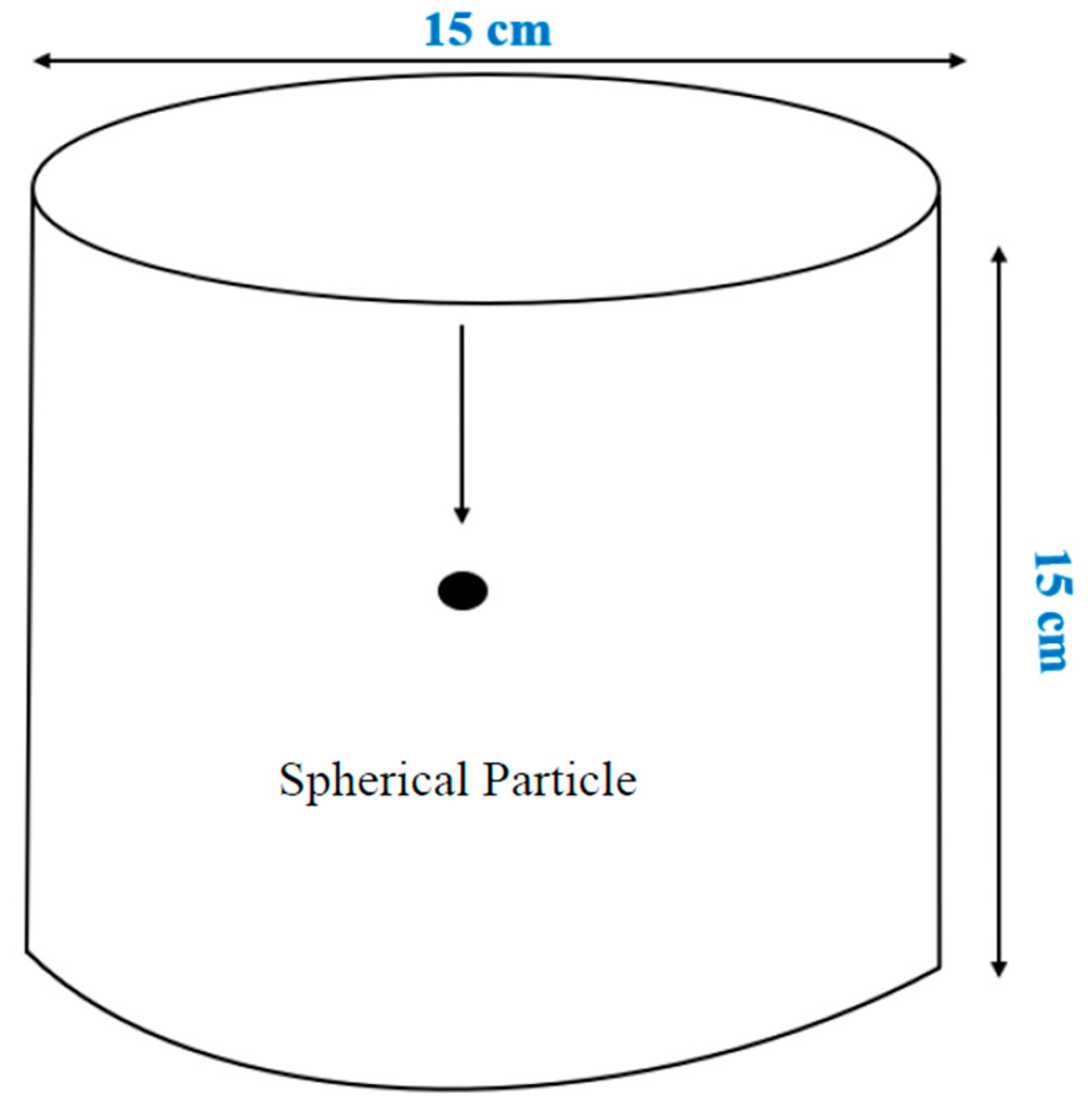
Figure 1 presents the unconfined graduated glass dimensions. The length was 15 cm, and the diameter was 15 cm, to ensure the glass wall did not impact the settling velocity measurements. The particles dropped freely in the unconfined fracture system. The ratio of the spherical diameter to the glass diameter was approximately 1:25, which is acceptable to avoid any effect of the glass walls.

2.2.2. Confined Fracture Model

Figure 2 shows the confined rectangular model with the following dimensions: the length was 60 cm, and the fracture widths were 10 or 7 mm. Rubbers that were placed between the parallel glasses were used to represent the fracture width, as shown in Figure 2. This rectangular model has two parallel visible glasses to allow measuring and to capture the solid settling velocity. In this study, the parallel glasses have smooth walls roughness. In our previous work [26] we observed that increasing wall roughness reduces proppant settling velocity. The friction reducer filled in the parallel fracture model and was left for an adequate time (one day) to make sure there were no bubbles in the fracture model.

2.3. Settling Velocity Procedure

The settling velocity measurements in the confined and unconfined models were evaluated using an advanced camera, which was arranged in front of the model. After the camera was turned on, a glass particle was dropped from the top to the bottom of the fracture model to measure the settling velocity of the particle. The particles need to be dropped carefully near the fracture entrance in the top to avoid any air bubbles that might stick to the spherical particles, as these can impact the settling velocity results. The settling measurement of the spherical particles was repeated at least three times to ensure the settling velocity was as accurate as possible. After every settling experiment measurement, the model was left for enough time (around 30 min) to allow the friction reducer inside the model to return to having a homogeneous structure before starting the next settling velocity experiment so that the upcoming experiment was not affected by the previous one. After recording videos of the settling measurements of the spherical glass particles using different particle diameter sizes and different friction reducer concentrations, an advanced software analyzed the spherical particle motion in the fracture models that were filmed and calculated the settling velocities.

3. Results and Analysis of Rheology Measurements

3.1. Viscosity Measurements

Figure 3 displays the flow curve and viscosity curve of the HVFR solutions. HVFRs are shear-thinning fluids, where increasing the shear rate leads to increasing shear stress. The viscosity properties (k and n) were obtained by drawing the power law curve of each friction reducer concentration. The results indicate that the consistency index k improved significantly as the friction reducer concentration increased. At 1 gpt, k was 0.1125, while at a higher concentration (8 gpt), k was 1.9291. However, the flow behavior index n exhibited an insignificant change in its values, specifically at high fracture fluid concentrations. The flow behavior index values were 0.4916, 0.3772, 0.3062, and 0.2601 for 1, 2, 4, and 8 gpt, respectively.
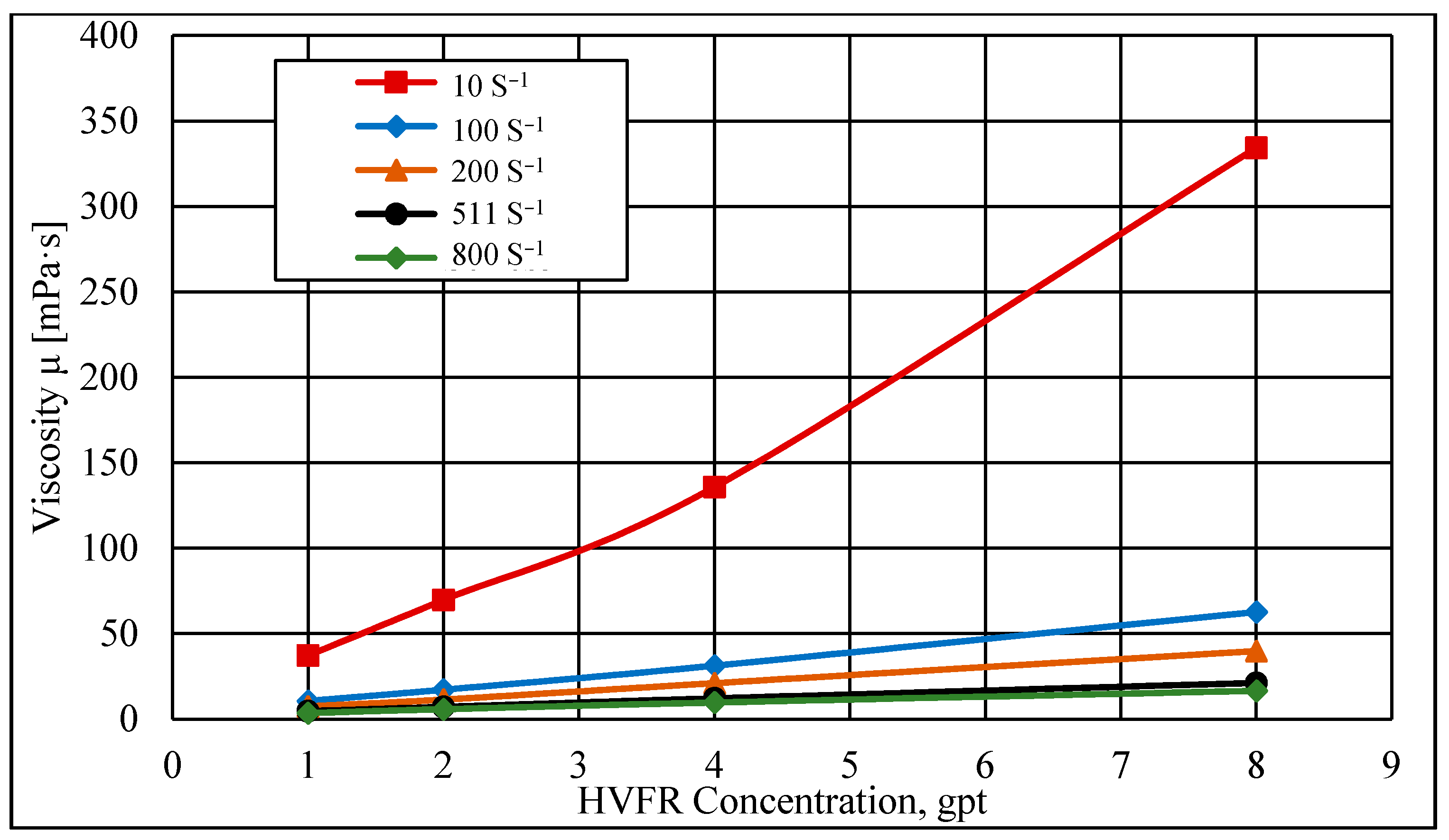
Figure 4 shows that the viscosity of the HVFR fluids improved substantially with increasing concentration but only at a low shear rate and this observation is consistent with previous results obtained by [27]. At a shear rate of 10 s−1, the viscosities of the HVFR were 334, 136, 70, and 37 mPa·s for 8, 4, 2, and 1 gpt, respectively. However, at a high shear rate of 100 s−1, the viscosities of the HVFRs reduced to 63, 31, 17, and 11 mPa·s for 8, 4, 2, and 1 gpt, respectively. Additionally, the significant reduction in the viscosities of the HVFRs at a high shear rate might imply that the HVFR viscosity did not significantly impact proppant transport near the wellbore. Therefore, at high shear rates, the reliability of the fluid viscosity might not provide good sand transport, and the fluid would have to depend on its elasticity to hold the proppant in the fracture networks. Moreover, the insignificant changes in the viscosities of the HVFRs that were observed at higher shear rates (Figure 4) suggest that increasing the concentration of the HVFRs above a certain level would not continue to improve the HVFR viscosity.

3.2. Temperature Effect on the HVFR Viscosity

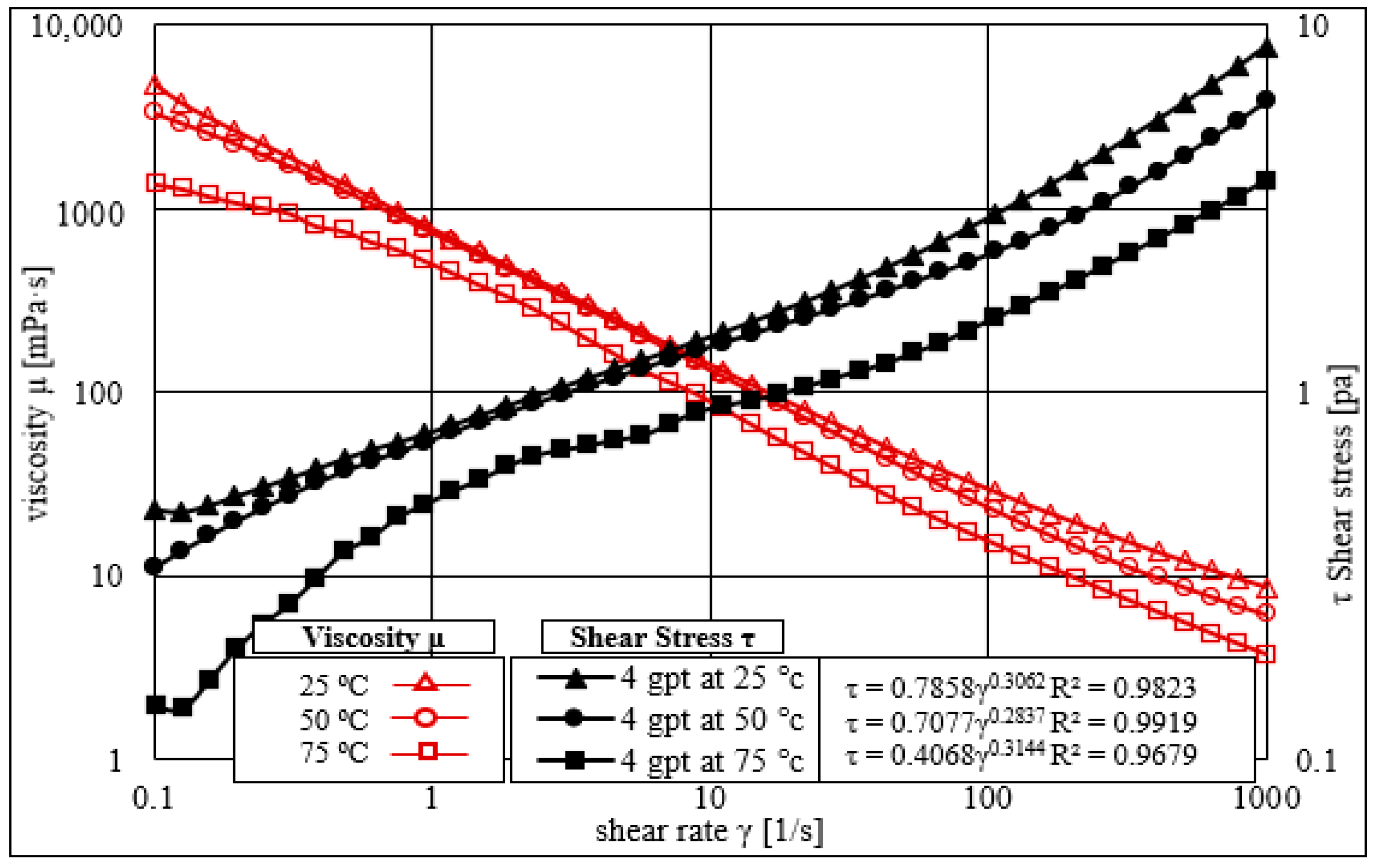
From the results presented in Figure 3 and Figure 4, a concentration of 4 gpt was selected for further laboratory investigations. Four temperature ranges (i.e., 25, 50, 75, and 100 °C) were used to understand the thermal stability of the HVFRs. A rheometer was used to investigate the impact of changing temperature of HVFR rheological properties. Figure 5 shows the impact of increasing the temperature above room temperature (25 °C) on the shear rate and shear stress profile for friction reducers of 4 gpt. The results using the HVFRs showed good resistance to a temperature at 50 °C; however, at 75 °C, the fluid exhibited a notable reduction in viscosity. The consistency index k was 0.7858, 0.7077, and 0.4068 for 25, 50, and 75 °C. However, the flow behavior index n did not show a significant change with increasing temperature. Similar observations were also noticed by [28] where viscosity decreased substantially in all concentrations of friction reducers. In summary, the HVFR at a concentration of 4 gpt showed better resistance to temperatures above 25 °C, but increasing the temperature to 75 °C or above led to a significant reduction in the HVFR viscosity.

3.3. Time-Dependent Temperature Effect on the HVFR Viscosity

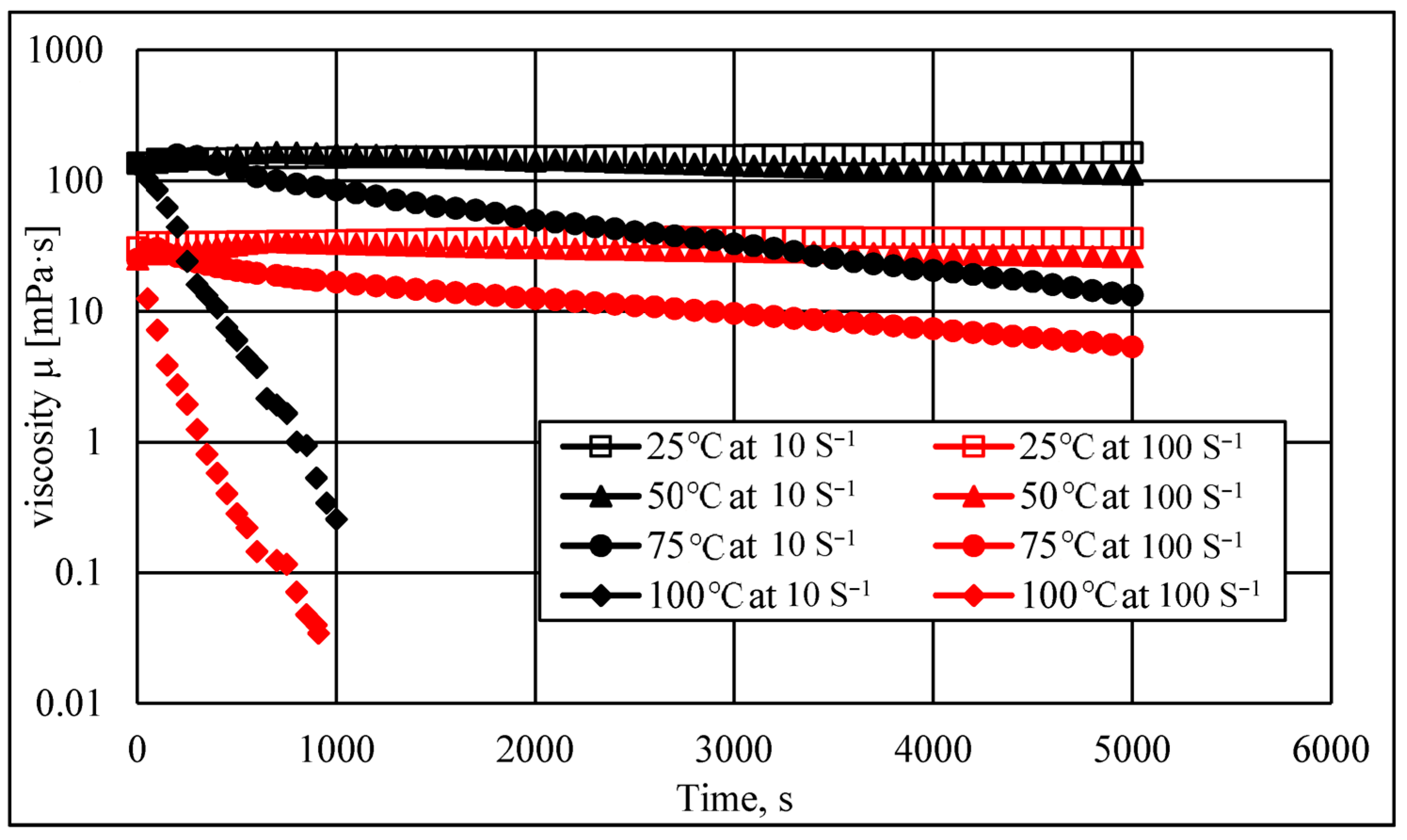
The HVFR viscosity changed as a function of time under the two shear rate values of 10 and 100 s−1. Figure 6 illustrates the influence of increasing the temperature using an HVFR concentration of 4 gpt. At a shear rate of 10 s−1, the results showed that the HVFR viscosity at 50 °C remained relatively stable, but after approximately 2000 s, the viscosity of the HVFR started to drop gradually. At the same shear rate, increasing the temperature to 75 °C caused the viscosity of the HVFR to decrease significantly after only 500 s. At higher temperature values of 100 °C, the HVFR started to lose its viscosity, and a portion of the solution started to evaporate after a very short period. These results could imply that HVFRs cannot maintain their viscosity at temperatures above 75 °C. The viscoelastic parameters of the fluids exhibit degradation in their rheological structure due to the strength of the interconnection between fluid’s molecules that reduce as temperature increases [29,30,31]. As a result, poor proppant transport would be observed inside the network fractures if this type of HVFR were used for high-temperature formations. Interestingly, when increasing the shear rate to 100 s−1, similar trends were observed, but a larger reduction in the fluid viscosity was also noticed for all temperature ranges compared to the viscosity measurements at low shear rates.

3.4. Elasticity Measurements

The elastic properties of fracturing fluid are vital to understand and determine because they contribute significantly to the efficiency of proppant transport inside fractures. The elasticity measurements of the HVFRs were made using a variety of fracture fluid concentrations. Relaxation time obtained from rheometer measurements was used to determine the elasticity of the fluid. It can be estimated from the crossover frequency of the loss modulus G″ and storage modulus G′. A long relaxation time means that the fluid has higher elastic properties compared to a fluid with a short relaxation time [32]. Figure 7 shows that the HVFR elasticity increased as the HVFR concentration increased. Relaxation time was 4.4, 9.3, 21.3, and 39.84 s for the HVFR concentrations of 1, 2, 4, and 8 gpt, respectively. Interestingly, compared to the viscosity profile, doubling the concentration of the HVFR from 4 to 8 gpt increased the relaxation time substantially, which implies that the elastic properties of HVFRs are in a similar linear relationship with the increasing concentration of HVFRs.
In summary, the HVFR concentration impacted the rheological properties substantially, but this only occurred until a certain level in terms of the viscosity properties. Table 2 summarizes the measurements of the consistency index (k), flow behavior index (n), and relaxation time for the different HVFR concentrations. In general, the viscosity and elastic properties of the HVFR improved significantly as the HVFRs increased.

3.5. Loss Factor or Damping Factor

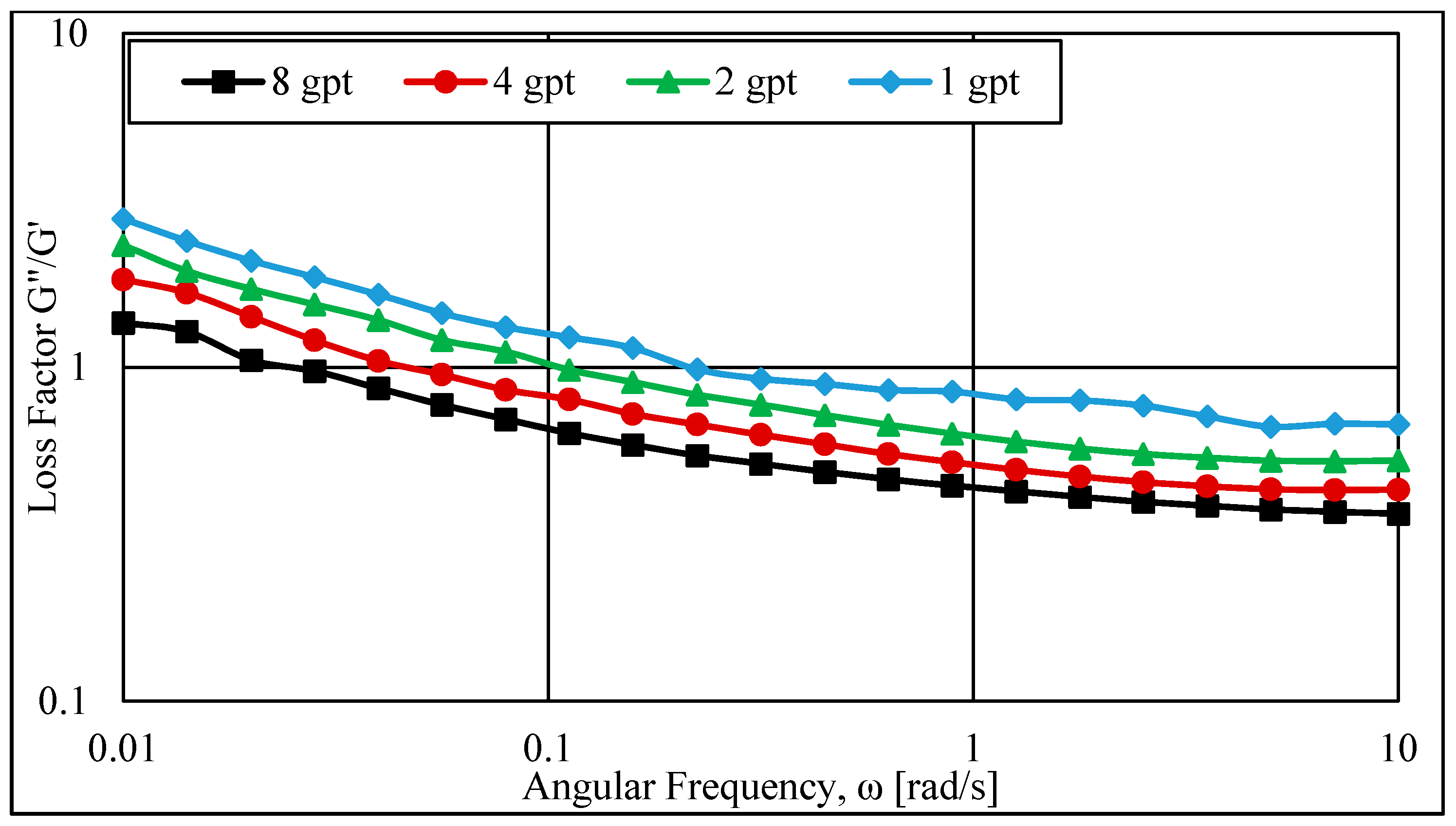
The loss factor describes the two portions of the viscoelastic behavior. Figure 8 presents the loss factor (tan θ) of the HVFR using different fluid concentrations that represent the ratio of the loss modulus (G″, viscous property) to the storage modulus (G′, elastic property). Figure 8 clearly exhibits that increasing the fracture fluid concentration reduced the loss factor as the HVFR concentrations increased from 1 to 8 gpt. Additionally, increases in the angular frequency decreased the loss factor for all HVFR concentrations. The elastic properties of the HVFR also dominated the viscosity properties as the HVFR concentration and angular frequency increased, which can be observed when G″/G′ became less than one.

4. Results and Analysis of the Spherical Particles Settling

The spherical particles settling velocity in creep regimes was measured using two fracture models: unconfined and confined fracture systems.

4.1. Settling Particle Velocities into Unconfined Fracture Systems

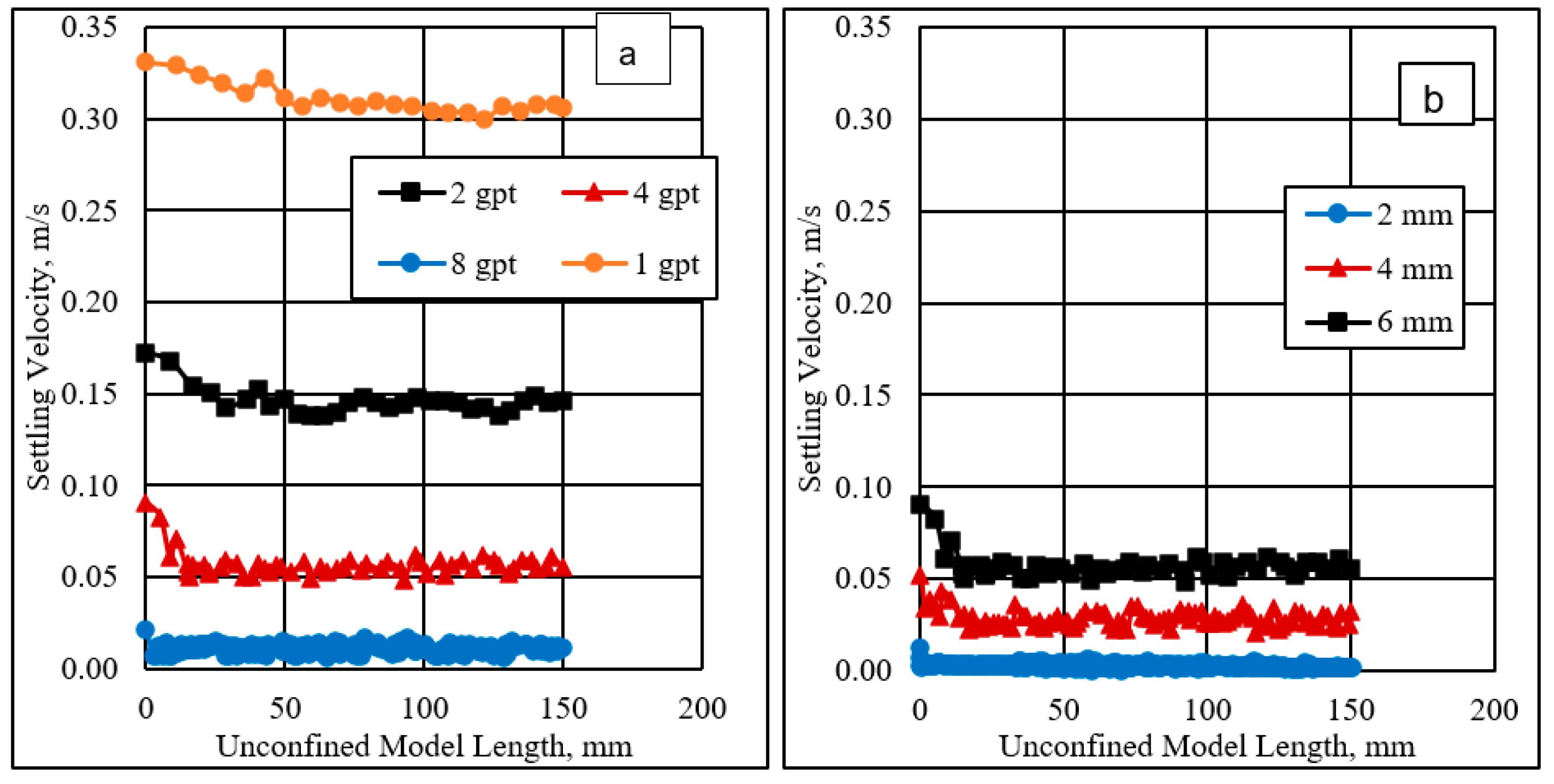
The settling velocity was measured for particles settling in different HVFR concentrations (i.e., 1, 2, 4, and 8 gpt). Three spherical particles (i.e., 2, 4, and 6 mm) were used in this investigation. Figure 9a displays the effect of an HVFR concentration on the settling particles using a 6 mm spherical particle size. The results indicate that the settling velocity was faster at a low HVFR concentration of 1 gpt compared to the high HVFR concentrations of 4 and 8 gpt. That could be due to the impact the HVFR viscosity and elasticity, which can hold particles for a significant time at higher fluid concentrations. Further investigation was conducted to understand the effect of different spherical particle sizes on the particle settling velocity using the HVFR with a 4 gpt concentration. Figure 9b shows that the settling velocity was more rapid for larger particle diameter sizes due to their volumes and weights being larger compared to the smaller particles. The terminal settling velocities of the spherical particles were 0.00133, 0.03167, and 0.05562 m/s for 2, 4, and 6 mm, respectively.

4.2. Reynolds Number and Drag Coefficient Calculations

The Reynolds number (RePL) was determined using Equation (1) [33], while the drag coefficient was calculated using Equation (2). The drag coefficient equation should be used if the Reynolds numbers are below 106 [34]. The fluid resistance that prevented the spherical particle from falling is represented by the drag coefficient.
R e P L = ρ f D p n V ( 2 n ) K .  
  C D = 24 R e P L + 2.6 ( R e P L 5 ) 1 + ( R e P L 5 ) 1.52 +   0.411 ( R e P L 263 , 000 ) 7.94 1 + ( R e P L 263 , 000 ) 8 + ( 0.25 ( R e P L 1 , 000 , 000 ) 1 + ( R e P L 1 , 000 , 000 ) )
where ρf is the fracture fluid density, Dp is the spherical particle diameter size, n is the flow behavior index, V is the settling velocity of the spherical particle, and K is the consistency index of the fluid.
Figure 10a shows the Reynolds number estimation for the three-particle diameter sizes (i.e., 2, 4, and 6 mm) at different HVFR concentrations (i.e., 1, 2, 4, and 8 gpt). The results indicate that the Reynolds number increased significantly for a low HVFR concentration of 1 gpt. This could be due to either the low viscosity or low elasticity of the HVFR at this concentration, which allows the spherical particle to settle quickly compared to other HVFR concentrations. At a spherical particle diameter of 6 mm, the Reynolds numbers were 122.35, 20.80, 1.98, and 0.053 for 1, 2, 4, and 8 gpt, respectively. In addition, the Reynolds number rose as the size of the particles increased.
Figure 10b shows the drag coefficient values versus the different particle sizes at different HVFR concentrations. The drag coefficient improved as the HVFR concentration increased. At a spherical diameter particle size of 6 mm, the drag coefficient values were 0.94, 2.50, 13.12, and 451.19 using 1, 2, 4, and 8 gpt, respectively.
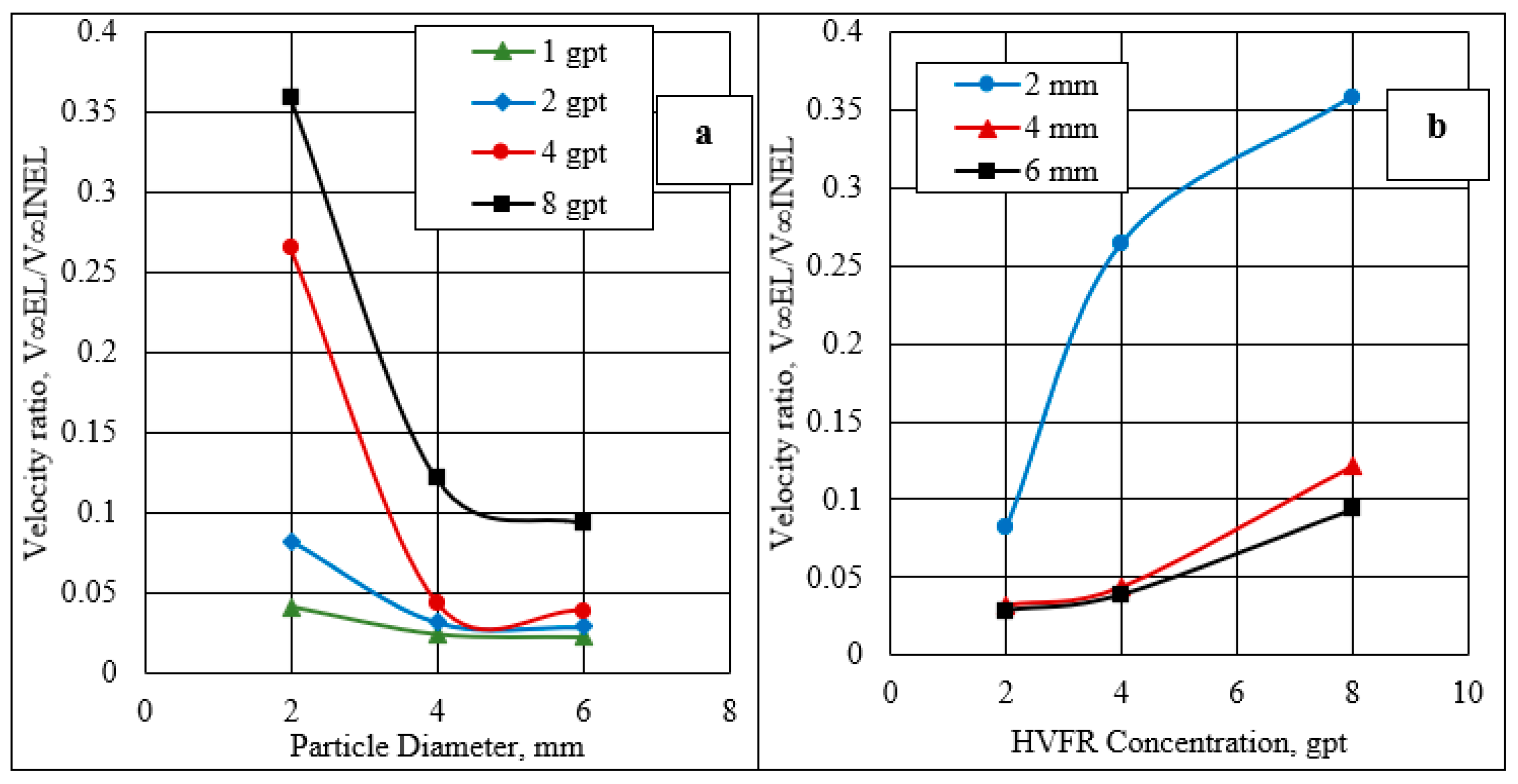
Further investigation was conducted using velocity ratio ( V E L V I N E L .) calculation to determine the HVFR elasticity impact on the settling rate. The velocity ratio of the spherical particle was measured using a variety of fluid concentrations and spherical particle sizes. The velocity ratio was determined by Equations (3)–(5) [35].
V E L V I N E L   = 1 + W e I N E L 2.42 n 7.8 1 + W e I N E L 3.15 n 6.86
W e I N E L = 2 λ V E L D p
V I N E L = ( R e P L K ρ f D p n ) 1 / ( 2 n )
where We is the Weissenberg number, λ is the relaxation time of the friction reducer, ρf is the fluid density, and Dp is the spherical particle diameter.
Figure 11 shows the velocity ratio using a variety of HVFR concentrations and spherical particle sizes. Figure 11a exhibits that the velocity ratio rose as the fracture fluid concentration increased. The concentration of 8 gpt exhibited the higher velocity ratio compared to 2 or 4 gpt. In addition, in Figure 11b, the spherical particle sizes also significantly impacted the velocity ratio, especially for smaller spherical particles. For instance, at 8 gpt, the solid particle with 2 mm had a higher velocity ratio compared to larger particles diameters, such as 4 and 6 mm.

4.3. Settling Particle Velocities in Confined Fracture Systems

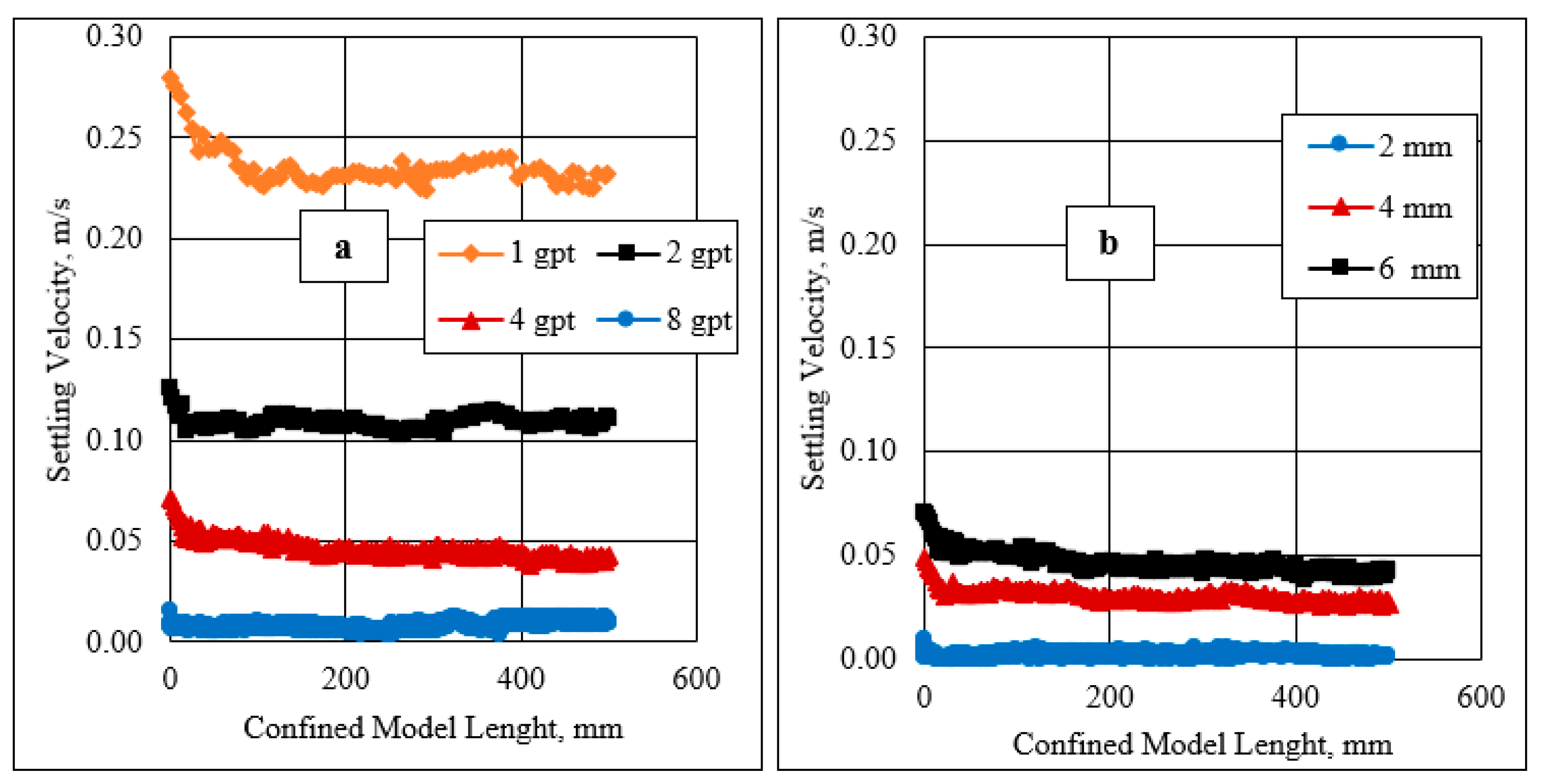
Figure 12 illustrates the settling velocity measurements of the spherical particles using different HVFR concentrations and a 10 mm fracture width. The results of the settling velocity into the confined system exhibited the same trend in the velocity as in the unconfined model both for the HVFR concentration and the spherical particle effects. However, the settling velocity in a confined system was slower than in the unconfined system. This occurred due to the presence of the wall effect where the spherical particles were governed by fracture width, but the spherical particles were in an unconfined system, allowing them to settle freely.

4.4. Fracture Width Effect

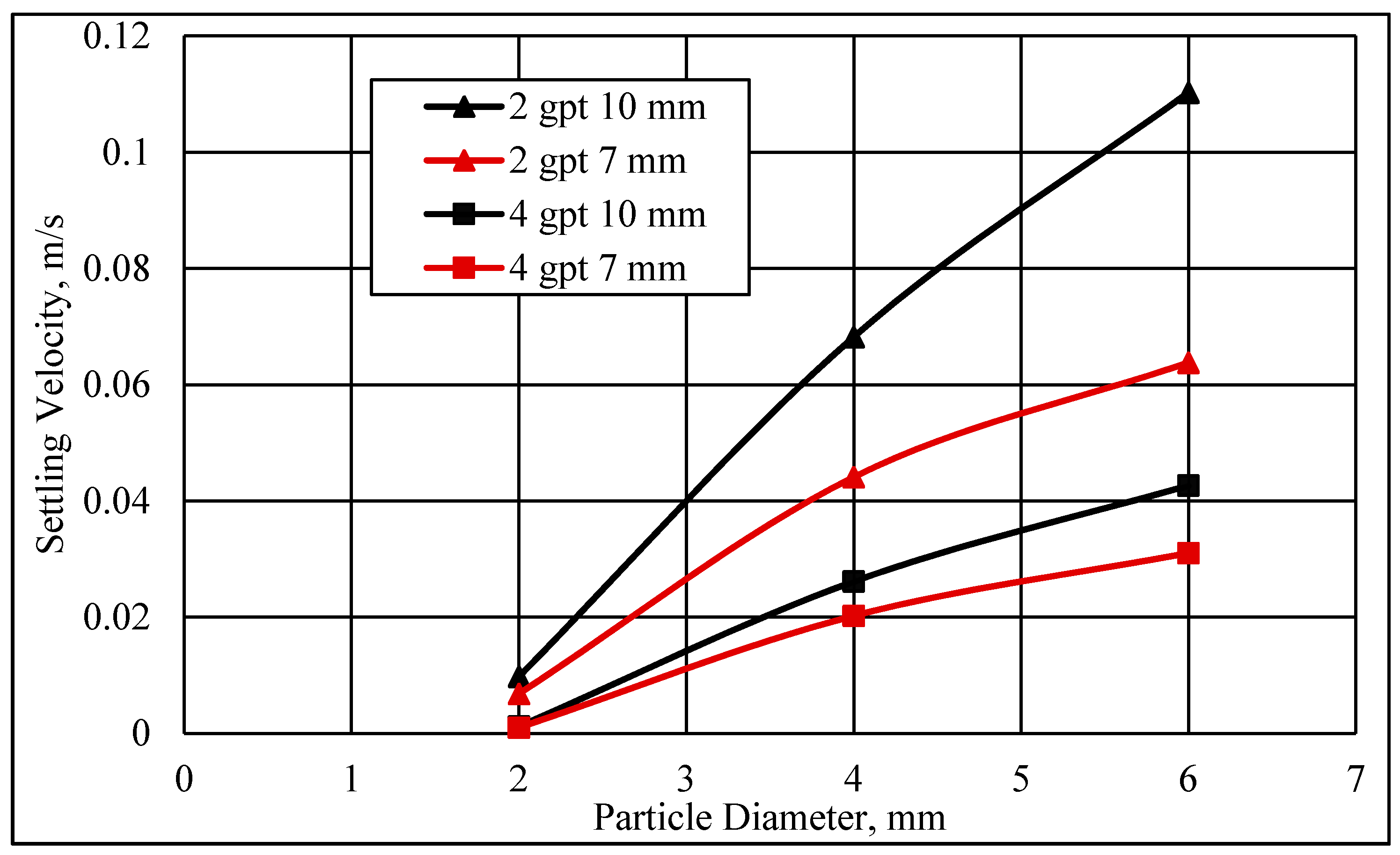
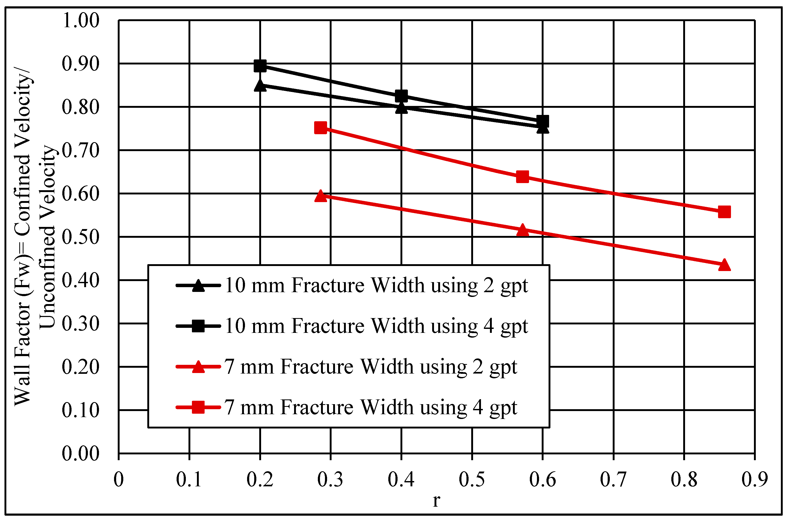
The effect of the fracture width was determined using two fracture widths, 7 and 10 mm. Figure 13 illustrates the impact of the fracture width on the settling velocity of the spherical particles that had fallen in fracture fluid concentrations of 2 and 4 gpt. The particle settling velocity decreased sharply when the fracture width was reduced, and the velocity was more pronounced at a low friction reducer concentration. Using a 6 mm particle diameter size and 2 gpt fluid concentration, the settling velocities were 0.11 and 0.064 m/s with a 10 and 7 mm fracture width, respectively. However, increasing the fluid concentration to 4 gpt led to better particle suspension in both fracture widths. This improvement in the proppant suspension could be due to the enhancement in the rheological properties of the fluid, which could create viscous layers on the fracture walls that would reduce the wall effect.
Further analysis of the wall effect was conducted using the settling velocity results presented in Figure 9 and Figure 12 for unconfined and confined fluids. The wall factor is a ratio of the settling velocity of the particle in a confined model to the settling velocity in an unconfined model, as presented in Equation (6) [35]. Figure 14 shows the wall factor (Fw) as a function of the dimensionless diameter (r), where r is the particle diameter over the fracture width. Based on two fracture widths (i.e., 7 and 10 mm), the wall factor decreased with an increase in the value of r. This happened because the impact of the wall retardation increased as the particle diameter size approached the wall spacing sizes. Additionally, unlike Newtonian fluids, the wall effect is not the only function relating the particle diameter to the fracture width ratio; there might be other factors, such as the HVFR elasticity and viscosity.
F w = the   settling   velocity   of   the   particle   in   a   confined   system   the   settling   velocity   of   the   particle   in   an   unconfined   system

4.5. Particle Concentration Effect

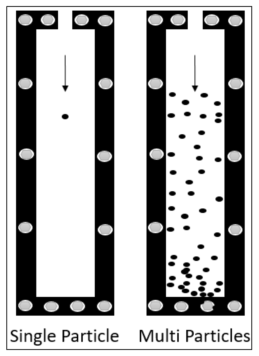
Figure 15 shows a simple confined fracture sketch for single particle settling in comparing to multiple particles settling. Figure 16 shows the settling velocity measurements for single and hindered settling velocity for multiple particles using three particle sizes (2, 4, and 6 mm) and 4 gpt HVFR within 10 mm fracture width. In concentrated suspension, sedimentation is influenced by other particles and hindered settling is observed. The settling velocity increased substantially due to the interaction with neighboring solid particles.
As shown in Figure 16a the terminal settling velocities of single particle were 0.00119, 0.02613, and 0.04265 m/s for 2, 4, and 6 mm, respectively. While in Figure 16b where the particle concentration was 1 lb/gal, the terminal settling velocities of multi particles were 0.022, 0.089, and 0.123 m/s for 2, 4, and 6 mm, respectively. However, Ref. [36] did not observe a change in settling velocity when particle concentration was higher than 10 lb/gal, this could occur because of their using of linear gel as fracture fluid. Increasing proppant concentration leads to increase the settling velocity of the proppant which may reflect on the fracture half-length to be shorter compared to lower proppant concentration during hydraulic fracture treatments in the field; however, high proppant concentration could means better formation conductivity that leads to improve the oil production [37].

4.6. Fracture Orientation Effect

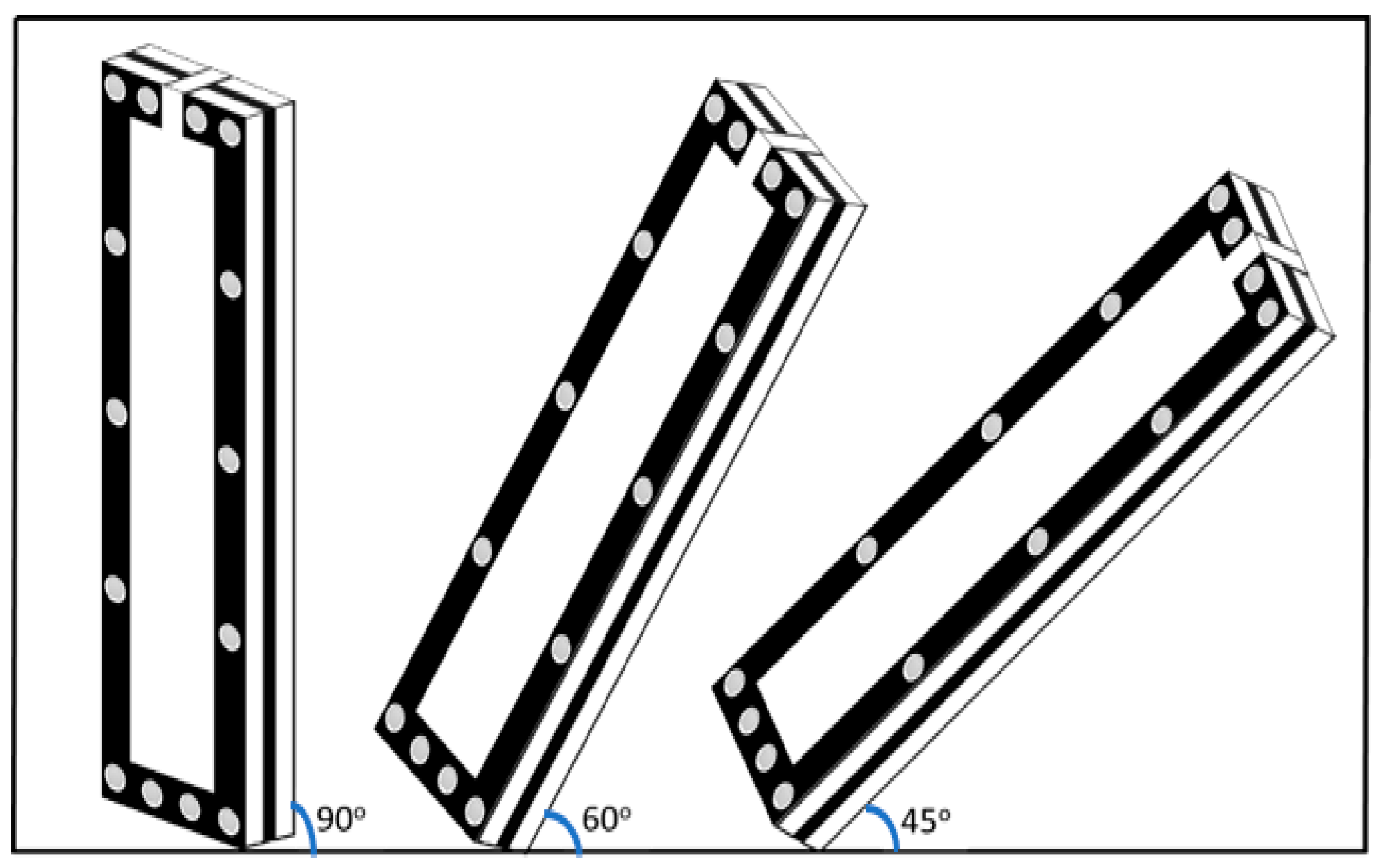
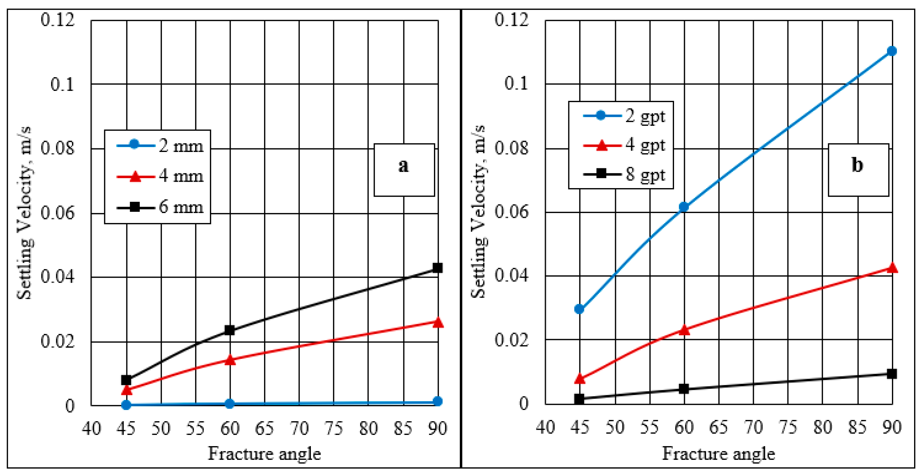
In the laboratory work described above, the settling velocities of different spherical particles were measured using different friction reducer concentrations at a fracture angulation of 90°. The lab setup in Figure 17 was used to study the impact of the fracture orientation on the settling velocity using a 10 mm fracture width. Figure 18 displays the settling velocity at different fracture orientations as a function of the proppant sizes and fracture fluid concentrations.
The results showed that increasing the inclination fracture from 90° to 45° decreased the settling velocity measurements. Using an HVFR of 4 gpt and the same particle size of 6 mm, the settling velocity in a vertical fracture was 0.042 m/s, and it decreased substantially to 0.007 m/s at a 45° inclined fracture. All of the results for various HVFR concentrations and particle sizes exhibited the same effect of fracture inclinations. This occurred because the particle settlement in the inclined fracture would be impacted by frictional force or contact beside the other forces. In addition, the particle touched the fracture sidewalls as it was transported along the fracture, causing a slower proppant settling rate. The roughness of the fracture slower the proppant settling rate [38,39]. This slower settling is attributed to the extra support force exerted by the inclined plane [40,41]. Thus, the frictional forces increased and the gravitational forces decreased, causing the proppant to take more time to reach the bottom of the fracture cell. In the settling experiments, this reduction in the settling velocity increased as the fracture angle decreased.
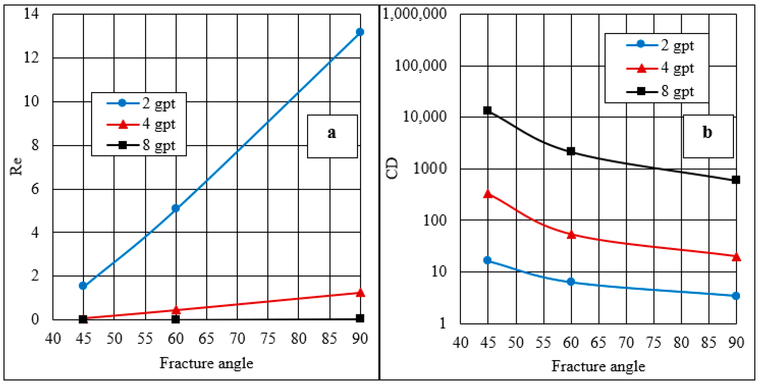
Figure 19a,b show that the fracture angle had a significant impact on the drag coefficient (CD). The drag coefficient decreased as the fracture angle increased to 90°. For all the HVFR concentrations, the CD decreased dramatically when the fracture angle was below approximately 60°, but only an insignificant reduction was observed beyond that.

5. Conclusions

This comprehensive study provides valuable information related to the rheology and particle settling velocity in HVFR fracture fluids. The rheological investigation studied the effect of the HVFR concentration, fluid temperature, and time-dependent temperature on the viscosity and elastic properties of the HVFR. The particle settling velocity investigation studied particle settling in confined and unconfined fracture systems. The following conclusions can be drawn from this research:
The viscosity and elastic properties of HVFRs provided excellent efficiency to transport particles for a significant time, which can provide a better distribution of the proppant in fracture networks.
At a high shear rate, the viscosity of HVFRs decreased sharply, so the viscosity would not provide good sand transport, and the fracture fluid may depend on its elasticity to hold the proppant.
Increasing the temperature cut the friction reducer efficiency to suspend the spherical particles, and that was observed clearly at temperatures that reached 75 °C.
The settling velocity of the spherical particles in the unconfined model was faster than the settling velocity in the confined model due to the absence of interference by the fracture wall.
As the ratio of the spherical particle diameter to the fracture width increased, so did the wall effect; however, the wall effect can be reduced by increasing the HVFR concentration.
The fracture angulation had a large impact on the particle settling, where the spherical particles had more contact with the fracture wall at a lower fracture angulation of 45° compared to vertical positions (90°), which may cause a reduction in the settling rate of the spherical particles.

6. Future Work

There are important factors that were not studied in this current research that should be evaluated to further understand the HVFR’s capability to suspend and transport particles, these are as follows:
The roughness of the surface of fracture walls has a significant impact on the settling velocity of particles where the smooth surface of the walls used in this current study could have the lowest impact on the particle settling velocity compared to roughened surfaces.
The effect of the temperature in this work was investigated only in rheology measurements. The settling velocity of spherical particles using a static model was measured at 25 °C, which has not been studied beyond this room temperature. Therefore, it is recommended to determine the particles settling at high-temperature ranges.

Author Contributions

G.B. and A.I. contributed to the design of the study, to the investigation of the outcomes, and to the writing of the manuscript. All authors have read and agreed to the published version of the manuscript.

Funding

No external funding.

Institutional Review Board Statement

Not applicable.

Informed Consent Statement

Not applicable.

Data Availability Statement

Not applicable.

Acknowledgments

The author is thankful to Sebha University for their guidance and assistance during his research study and sends his gratefulness to the Libyan Ministry of Higher Education and Scientific Research for funding him to study Ph.D. in the United States. The authors would like to express appreciation to SNF Holding Company for offering polyacrylamide samples of high viscosity friction reducers.

Conflicts of Interest

The authors declare no conflict of interest.

Abbreviations

CDDrag coefficient
DPSpherical particle diameter, m
G′Storage modulus, Pa
GLoss modulus, Pa
KFlow consistency index, Pa.sn
nFlow behavior index
RePLReynold’s number of proppants settling
Velocity in a power low liquid
VSetting proppant velocity, m/s
ρfFluid density, kg/m3
μViscosity, mPa·s
ωAngular frequency, rad/s
λ Relaxation time of the friction reducer
Fwwall factor
ReReynold’s number
WeWeissenberg number
V E L Settling velocity in viscoelastic fluids, m/s
V I N E L Settling velocity in inelastic fluids, m/s
W e I N E L Dimensionless number relating the relaxation time to particle diameter and unconfined settling velocity

References

  1. Acharya, A.; Mashelkar, R.A.; Ulbrecht, J. Flow of inelastic and viscoelastic fluids past a sphere. Rheol. Acta 1976, 15, 454–470. [Google Scholar] [CrossRef]
  2. Acharya, A.R. Particle Transport in Viscous and Viscoelastic Fracturing Fluids. SPE Prod. Eng. 1986, 1, 104–110. [Google Scholar] [CrossRef]
  3. Acharya, A.R. Viscoelasticity of Crosslinked Fracturing Fluids and Proppant Transport. SPE Prod. Eng. 1988, 3, 483–488. [Google Scholar] [CrossRef]
  4. Arnipally, S.K.; Kuru, E. Settling Velocity of Particles in Viscoelastic Fluids: A Comparison of the Shear-Viscosity and Elasticity Effects. SPE J. 2018, 23, 1689–1705. [Google Scholar] [CrossRef]
  5. Chhabra, R.P. Wall effects on spheres falling axially in cylindrical tubes. In Transport Processes in Bubbles, Drops and Particles, 2nd ed.; CRC press: Boca Raton, FL, USA, 2002. [Google Scholar]
  6. Chhabra, R. Bubbles Drops and Particles in Non-Newtonian Fluids Second Edition; CRC press: Boca Raton, FL, USA, 2007. [Google Scholar]
  7. Harris, P.C.; Walters, H.G.; E Bryant, J. Prediction of Proppant Transport From Rheological Data. SPE Prod. Oper. 2009, 24, 550–555. [Google Scholar] [CrossRef]
  8. Johnson, M.; Winkler, A.; Aften, C.; Sullivan, P.; Hill, W.A.; VanGilder, C. Successful Implementation of High Viscosity Friction Reducer in Marcellus Shale Stimulation. In Proceedings of the SPE/AAPG Eastern Regional Meeting, Pittsburgh, PA, USA, 7 October 2018. [Google Scholar] [CrossRef]
  9. Dahlgren, K.; Green, B.; Williams, B.; Inscore, J.; Van Domelen, M.; Fenton, A. Case Studies of High Viscosity Friction Reducers HVFR in the STACK Play. In Proceedings of the SPE Hydraulic Fracturing Technology Conference and Exhibition, The Woodlands, TX, USA, 23 January 2018. [Google Scholar] [CrossRef]
  10. White, C.M.; Mungal, M.G. Mechanics and Prediction of Turbulent Drag Reduction with Polymers. Ann. Rev Fluid Mech. 2008, 40, 235–256. [Google Scholar] [CrossRef]
  11. Sun, H.; Wood, B.; Stevens, R.F.; Cutler, J.; Qu, Q.; Lu, M. A Nondamaging Friction Reducer for Slickwater Frac Applications. Soc. Pet. Eng. 2011. [Google Scholar] [CrossRef]
  12. Tomson, R.C.; Guraieb, P.; Graham, S.; Yan, C.; Ghorbani, N.; Hanna, T.; Cooper, C. Development of a Universal Ranking for Friction Reducer Performance. Soc. Pet. Eng. 2017. [Google Scholar] [CrossRef]
  13. Khan, S.; Shen, L.; Everson, N. Engineered Friction Reducers Enhance Proppant Transport. E&P Magazine. Available online: https://www.hartenergy.com/exclusives/engineered-friction-reducers-enhance-proppant-transport-176821 (accessed on 2 January 2018).
  14. Sareen, A.; Zhou, M.J.; Zaghmoot, I.; Cruz, C.; Sun, H.; Qu, Q.; Li, L. Successful Slickwater Fracturing in Ultrahigh TDS Produced Water by Novel Environmentally Preferred Friction Reducer. In Proceedings of the International Petroleum Technology Conference, Kuala Lumpur, Malaysia, 10 December 2014. [Google Scholar] [CrossRef]
  15. Van Domelen, M.; Cutrer, W.; Collins, S.; Ruegamer, M. Applications of Viscosity-Building Friction Reducers as Fracturing Fluids. In Proceedings of the SPE Oklahoma City Oil and Gas Symposium, Oklahoma City, OK, USA, 27 March 2017. [Google Scholar] [CrossRef]
  16. Clark, R.K.; Scheuerman, R.F.; Rath, H.; Van Laar, H.G. Polyacrylamide/Potassium-Chloride Mud for Drilling Water-Sensitive Shales. Soc. Pet. Eng. 1976, 28, 719–727. [Google Scholar] [CrossRef]
  17. Ryles, R.; Cicchiello, J. New Polymers for EOR Applications. In Proceedings of the SPE Enhanced Oil Recovery Symposium, Tulsa, OK, USA, 20 April 1986. [Google Scholar] [CrossRef]
  18. Blamble, E.A.; Pyncheon, J. Guar Replacement with Synthetic Polymers—Utica Shale Case Histories. In Proceedings of the SPE International Conference and Exhibition on Formation Damage Control, Lafayette, LA, USA, 24 February 2016. [Google Scholar] [CrossRef]
  19. Aften, C. Analysis of Various High Viscosity Friction Reducers and Brine Ranges Effectiveness on Proppant Transport. In Proceedings of the SPE/AAPG Eastern Regional Meeting, Pittsburgh, PA, USA, 7–11 October 2018. [Google Scholar] [CrossRef]
  20. Geri, M.B.; Imqam, A.; Bogdan, A.; Shen, L. Investigate The Rheological Behavior of High Viscosity Friction Reducer Fracture Fluid and Its Impact on Proppant Static Settling Velocity. In Proceedings of the SPE Oklahoma City Oil and Gas Symposium, Oklahoma City, OK, USA, 8 April 2019. [Google Scholar] [CrossRef]
  21. Kurdi, M.; Sadykov, A.; Momin, A.; Rueda, J.; Kazakoff, S.; Baki, S.; Mechkak, K.; Kalbani, A. Application of High Viscous Friction Reducers in Saudi Unconventional Reservoirs. In Proceedings of the International Petroleum Technology Conference, Dhahran, Saudi Arabia, 13 January 2020. [Google Scholar] [CrossRef]
  22. Zhao, H.; Danican, S.; Torres, H.; Christanti, Y.; Nikolaev, M.; Makarychev-Mikhailov, S.; Bonnell, A. Viscous Slickwater as Enabler for Improved Hydraulic Fracturing Design in Unconventional Reservoirs. In Proceedings of the SPE Annual Technical Conference and Exhibition, Dallas, TX, USA, 24 September 2018. [Google Scholar] [CrossRef]
  23. Ghith, B.; Imqam, A. Proppant Transport by High Viscosity Friction Reducer and Guar Linear Gel-Based Fracture Fluids. In Proceedings of the 54th U.S. Rock Mechanics/Geomechanics Symposium, Physical Event Cancelled, Golden, CO, USA, 28 June 2020. [Google Scholar]
  24. Geri, M.B.; Imqam, A.; Shen, L.; Bogdan, A.; Flori, R. Static Proppant Settling Velocity Characteristics in High Viscosity Friction Reducers Fluids for Unconfined and Confined Fractures. In Proceedings of the 53rd U.S. Rock Mechanics/Geomechanics Symposium, New York, NY, USA, 23 June 2019. [Google Scholar]
  25. Shen, L.; Vigderman, L.; Heller, D.; Fu, D. Can Friction Reducers Transport Sand During Fracturing Treatment? In Proceedings of the SPE/AAPG/SEG Unconventional Resources Technology Conference, Houston, TX, USA, 23 July 2018. [Google Scholar] [CrossRef]
  26. Kadhim, D.A.; Dunn-Norman, S.; Imqam, A. Ceramic Proppant Transport and Placement in Heterogeneous Fracture Systems. In Proceedings of the SPE/AAPG/SEG Unconventional Resources Technology Conference, Austin, TX, USA, 24 July 2017. [Google Scholar] [CrossRef]
  27. Hu, Y.T.; Fisher, D.; Kurian, P.; Calaway, R. Proppant Transport by a High Viscosity Friction Reducer. In Proceedings of the SPE Hydraulic Fracturing Technology Conference and Exhibition, The Woodlands, TX, USA, 23 January 2018. [Google Scholar] [CrossRef]
  28. Sanders, M.; Felling, K.; Thomson, S.; Wright, S.; Thorpe, R. Dry Polyacrylamide Friction Reducer: Not Just for Slick Water. In Proceedings of the SPE Hydraulic Fracturing Technology Conference, The Woodlands, TX, USA, 1 February 2016. [Google Scholar] [CrossRef]
  29. Swiecinski, F.; Reed, P.; Andrews, W. The Thermal Stability of Polyacrylamides in EOR Applications. In Proceedings of the SPE Improved Oil Recovery Conference, Tulsa, OK, USA, 11 April 2016. [Google Scholar] [CrossRef]
  30. Almubarak, T.; Ng, J.H.; Sokhanvarian, K.; AlKhaldi, M.; Nasr-El-Din, H. Improving Hydraulic Fracturing Fluids Through Dual Polymer Technology. In Proceedings of the SPE Annual Technical Conference and Exhibition, Dallas, TX, USA, 24 September 2018. [Google Scholar] [CrossRef]
  31. Gautam, S.; Guria, C. Optimal Synthesis, Characterization, and Performance Evaluation of High-Pressure High-Temperature Polymer-Based Drilling Fluid: The Effect of Viscoelasticity on Cutting Transport, Filtration Loss, and Lubricity. SPE J. 2020, 25, 1333–1350. [Google Scholar] [CrossRef]
  32. Geri, M.B.; Ellafi, A.; Ofori, B.; Flori, R.; Sherif, H. Successful Implementation of High Viscosity Friction Reducers from Laboratory to Field Scale: Middle Bakken Case Study. In Proceedings of the SPE/AAPG/SEG Unconventional Resources Technology Conference, Denver, CO, USA, 22 July 2019. [Google Scholar] [CrossRef]
  33. Chhabra, R.P. Bubbles, Drops, and Particles in Non-Newtonian Fluids; CRC press: Boca Raton, FL, USA, 2006. [Google Scholar]
  34. Morrison, F.A. Data Correlation for Drag Coefficient for Sphere; Department of Chemical Engineering, Michigan Technological University: Houghton, MI, USA, 2013; p. 49931. [Google Scholar]
  35. Malhotra, S.; Sharma, M.M. Settling of spherical particles in unbounded and confined surfactant-based shear thinning viscoelastic fluids: An experimental study. Chem. Eng. Sci. 2012, 84, 646–655. [Google Scholar] [CrossRef]
  36. McMechan, D.; Shah, S. Static Proppant-Settling Characteristics of Non-Newtonian Fracturing Fluids in a Large-Scale Test Model. Soc. Pet. Eng. 1991, 6, 305–312. [Google Scholar] [CrossRef]
  37. Ellafi, A.; Jabbari, H.; Geri, M.B.; Alkamil, E. Can HVFRs Increase the Oil Recovery in Hydraulic Fractures Applications? In Proceedings of the Abu Dhabi International Petroleum Exhibition & Conference, Abu Dhabi, UAE, 11 November 2019. [Google Scholar] [CrossRef]
  38. Xiao, B.; Huang, Q.; Chen, H.; Chen, X.; Long, G. A fractal model for capillary flow through a single tortuous capillary with roughened surfaces in fibrous porous media. Fractals 2021, 29, 2150017. [Google Scholar] [CrossRef]
  39. Xiao, B.; Liu, Y.; Chen, H.; Chen, X.; Long, G. A Novel Fractal Solution for Laminar Flow Resistance in Roughened Cylindrical Microchannels. Fractals 2020, 28, 2050097. [Google Scholar] [CrossRef]
  40. Kou, R.; Moridis, G.J.; Blasingame, T. Field Scale Proppant Transport Simulation and Its Application to Optimize Stimulation Strategy. In Proceedings of the SPE/AAPG/SEG Unconventional Resources Technology Conference, Houston, TX, USA, 23 July 2018. [Google Scholar] [CrossRef] [Green Version]
  41. Geri, M.B.; Imqam, A.; Dunn-Norman, S. Proppant Transport Behavior in Inclined Versus Vertical Hydraulic Fractures: An Experimental Study. In Proceedings of the SPE/AAPG Eastern Regional Meeting, Pittsburgh, PA, USA, 7 October 2018. [Google Scholar] [CrossRef]
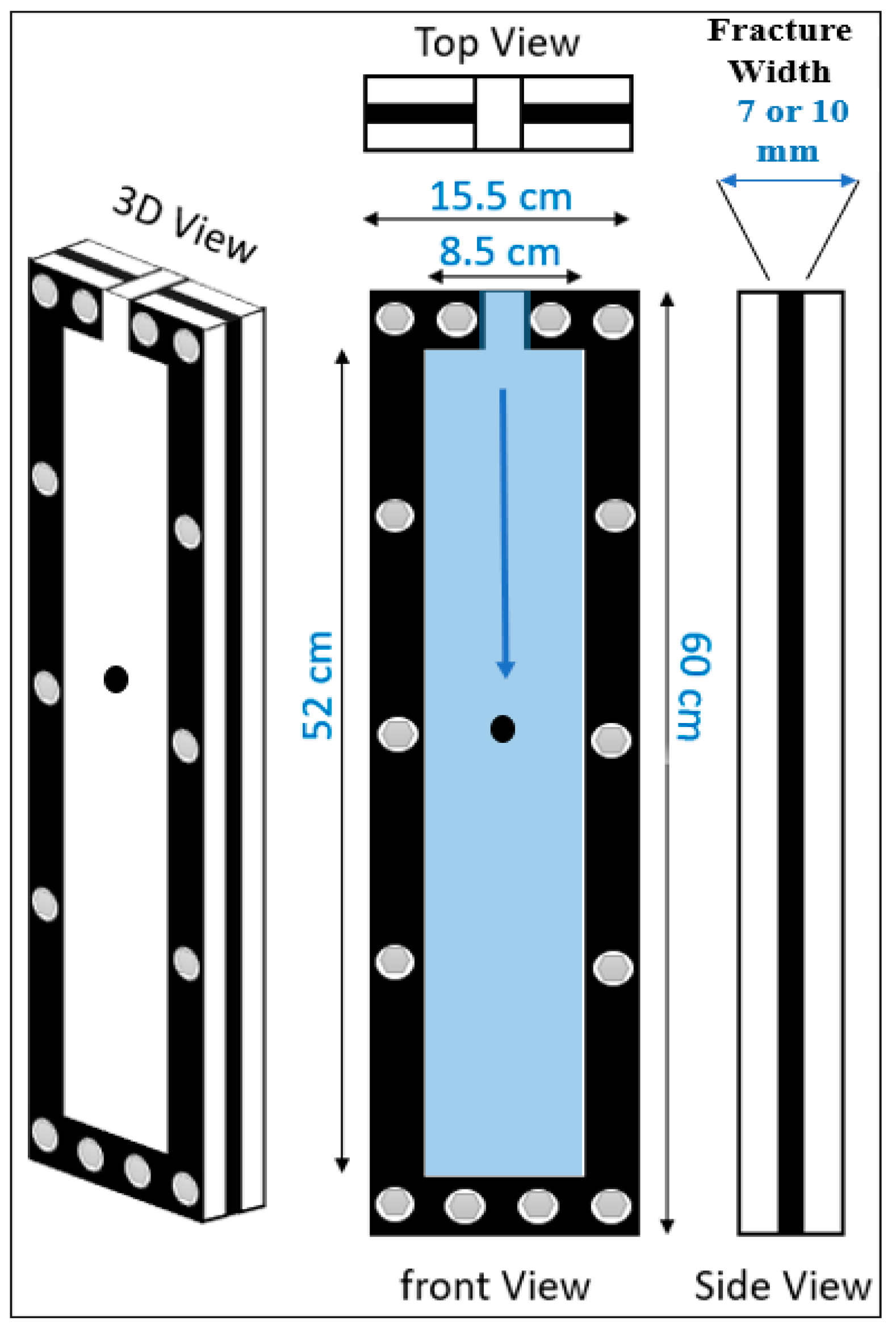
Figure 1. Unconfined fracture fluid system.
Energies 14 02462 g001
Figure 2. Confined fracture fluid system.
Energies 14 02462 g002
Figure 3. Flow curves and viscosity curves for the HVFR concentrations measured at 25 °C.
Energies 14 02462 g003
Figure 4. Viscosity curve of HVFR concentrations at different shear rates.
Energies 14 02462 g004
Figure 5. Flow curves and viscosity curves for the HVFR measured at various temperatures.
Energies 14 02462 g005
Figure 6. Time-dependent temperature effect on the viscosity at different temperature values.
Energies 14 02462 g006
Figure 7. Elastic properties of the HVFR at different concentrations at 25 °C.
Energies 14 02462 g007
Figure 8. Loss factor (G″/G′) of the HVFR.
Energies 14 02462 g008
Figure 9. Terminal spherical particle settling in the unconfined model: (a) HVFR concentrations and (b) particle sizes impact.
Energies 14 02462 g009
Figure 10. (a) Reynolds number and (b) drag coefficient estimations in the unconfined model.
Energies 14 02462 g010
Figure 11. Velocity ratio using: (a) friction reducer concentrations and (b) spherical particle sizes.
Energies 14 02462 g011
Figure 12. Terminal spherical particle settling in the confined model using (a) 6 mm particle size, and (b) 4 gpt HVFR concentration.
Energies 14 02462 g012
Figure 13. Terminal settling velocity of spherical particles using two fracture widths and two friction reducer concentrations.
Energies 14 02462 g013
Figure 14. Wall effect using two fracture widths and two friction reducer concentrations.
Energies 14 02462 g014
Figure 15. Solid particle effect in confined fracture fluid system.
Energies 14 02462 g015
Figure 16. Terminal settling velocity of spherical particles using (a) single particle and (b) multi particles.
Energies 14 02462 g016
Figure 17. Effect of fracture angulation on the settling velocity of spherical particles.
Energies 14 02462 g017
Figure 18. Effect of the fracture angulation on the settling velocity using (a) 4 gpt concentration, and (b) 6 mm particle size.
Energies 14 02462 g018
Figure 19. Fracture angulation effect on (a) Re and (b) CD using a 6 mm particle size and different HVFR concentrations.
Energies 14 02462 g019
Table 1. Characteristics of glass spherical particles at different diameters.
Glass Bubble Diameter, mmDensity, g/cm3
22.6253
42.6261
62.626
Table 2. Rheological properties of HVFRs using different concentrations at 25 °C.
Fluid Concentration,
gpt
Fluid Density, g/cm3Relaxation Time, sConsistency Index, kFlow Behavior Index, nR2
10.9964.4640.11250.49160.9968
20.9979.3460.30770.37720.9929
40.99721.3220.78580.30620.9823
80.99839.84061.92910.26010.9883
Publisher’s Note: MDPI stays neutral with regard to jurisdictional claims in published maps and institutional affiliations.