Article

Combustion Modes and Unsteady Characteristics during the Condition Transition of a Scramjet Combustor

Science and Technology on Scramjet Laboratory, College of Aerospace Science and Engineering, National University of Defense Technology, Changsha 410073, China
*
Author to whom correspondence should be addressed.
Energies 2021, 14(9), 2522; https://doi.org/10.3390/en14092522
Submission received: 6 March 2021 / Revised: 20 April 2021 / Accepted: 25 April 2021 / Published: 28 April 2021

Abstract

:
To investigate the combustion modes and unsteady characteristics during the condition transition of a scramjet combustor, a series of experiments were carried out under the condition of Mach 2.52 supersonic incoming flow, the corresponding stagnation pressure and temperature of which were 1.6 MPa and 1486 K, respectively. A fuel supply system that could dynamically adjust the injection pressure was adopted to simulate the condition transition stage of a scramjet. Based on the advanced combustion diagnosis technique, the transient chemiluminescence image and the wall pressure were recorded during the whole combustion process. Three typical modes of turbulent combustion occurred when the injection pressure drop gradually increased. The jet flame was stable after the condition transition when the injection pressure drop was relatively low. An unstable combustion phenomenon accompanied by intermittent local extinction and reignition could be found near the blowout limits. With a further increase in the injection pressure drop, the flame was blown out quickly during the transition process. In addition, the flame development characteristics during condition transition under stable combustion mode and the effect of injection pressure drop were studied in detail. During the process of switching between the two conditions, the area and light intensity of the flame decreased over time, and the wall pressure was accordingly reduced. As the increase in injection pressure dropped, the intensity of chemical reactions deceased obviously and the transition time became longer.

1. Introduction

Due to their excellent performance, scramjets are regarded as one of the most ideal propulsion systems in hypersonic vehicles [1,2,3,4]. During actual flight, aircraft inevitably have to perform altitude adjustment, flexible maneuvering, and condition transition. During these processes, the incoming flow parameters and the global equivalence ratio change dramatically. The flame in the combustor may oscillate violently and may even be extinguished, which threatens the safety of the entire flight mission. It is necessary to clarify the combustion modes during the condition transition.
Compared to past research, recent investigations have focused on the flow characteristics and flame stabilization mechanism in cavity-based combustors [5,6,7,8]. For instance, Micka et al. [9] experimentally studied the combustion characteristics of fuel injected upstream of the cavity in the flight Mach numbers of 4.3–5.4 and observed two flame stability modes. Based on the stagnation temperature of incoming flow, one combustion mode is the cavity-stabilized combustion mode and the other is the jet-wake flame stabilization mode. These two combustion modes were also found in a hydrogen-fueled scramjet combustor at high total temperature [10]. A shear-layer-stabilized flame and a recirculation-zone-stabilized flame were proposed in a study on the combustion characteristics of kerosene [11]. Wang et al. [12] also studied the combustion modes of a hydrogen jet at flight Mach 6 conditions and observed three different flame stabilization modes. Tian et al. [13] found that there were two flame stabilization modes for hydrogen. The scramjet mode corresponded to cavity shear-layer-stabilized combustion, and the flame of the ramjet mode was combined with cavity shear-layer- and recirculation-stabilized combustion. In addition, many researchers have focused on subsonic and supersonic combustion modes in dual-mode scramjet engines [14,15]. The current research has focused on the flame stabilization mode under a fixed equivalence ratio, but there is little research on the switching process between different flame stabilization modes.
The flame in a combustor is not always stable and, in some situations, its oscillation characteristics cannot be ignored. Although incoming flow is supersonic, there are still some subsonic regions in a combustor, such as the boundary layer, separation zone, and recirculation zone [16]. Furthermore, the interaction between a shockwave and shear layer is inherently unstable [17,18]. Lin et al. [19] noticed the thermoacoustic instabilities in an ethylene-fueled scramjet in the flight Mach numbers of 3.5–5.0 and found that the oscillation frequencies were in the range of 100–400 Hz. Wang et al. [20] revealed that combustion oscillation was closely related to the mixing status. The flame in a cavity with a larger aft angle oscillated more strongly, and the flame front was closer to the upstream location than that in a cavity with a smaller aft angle [21]. When the equivalence ratio is at a higher level, the flame structure shows a quasiperiodic low-frequency oscillation [22]. As the equivalence ratio increases, the combustion oscillation becomes more regular and frequent [23]. With the change in premixing distance, an ethylene flame exhibits two different combustion oscillation modes [24]. One oscillation mode is small-amplitude, high-frequency fluctuation, and the other is large-amplitude, low-frequency fluctuation. In addition, the flame oscillation characteristics in multiple-orifice cases are obviously different from those in single-orifice cases [25]. The characteristics of combustion oscillations have been observed in previous studies, but there is no research showing whether combustion oscillations occur after the equivalence ratio is reduced.
The flame in a combustor is difficult to maintain under certain conditions, and it can be blown out. When the equivalence ratio is low, kerosene can be successfully ignited by the pilot flame while the flame blowout phenomenon still occurs [26]. The phenomenon of flame blowout mainly occurs due to the local mixture being below the flammable limits [27,28]. The flame front becomes more distorted with a high Karlovitz [29,30]. The local flame blowout phenomenon is induced by turbulence under a high Karlovitz [31]. The flame extinction is also related to the high local scalar dissipation rate [32]. Furthermore, there are a variety of factors that affect the blowout limits, such as the cavity geometry [33], fuel injection scheme [34], fuel type [35], and incoming flow parameters [36].
Although sufficient studies have been conducted for a variety of combustion modes under a fixed equivalence ratio and a few studies have focused on dynamic development of unsteady combustion during the mode transition of a dual-mode scramjet [37,38,39], there are few investigations on the process of condition transition of a scramjet combustor at full length. The condition transition as described in this paper mainly refers to the change in a global equivalence ratio, which was realized by dynamically adjusting the injection pressure in the experiments. In this paper, three kinds of combustion modes in a scramjet during the process of condition transition were experimentally investigated. Furthermore, the flame development characteristics during the transition process under stable combustion modes and the effect of the injection pressure drop were studied in detail.

2. Materials and Methods

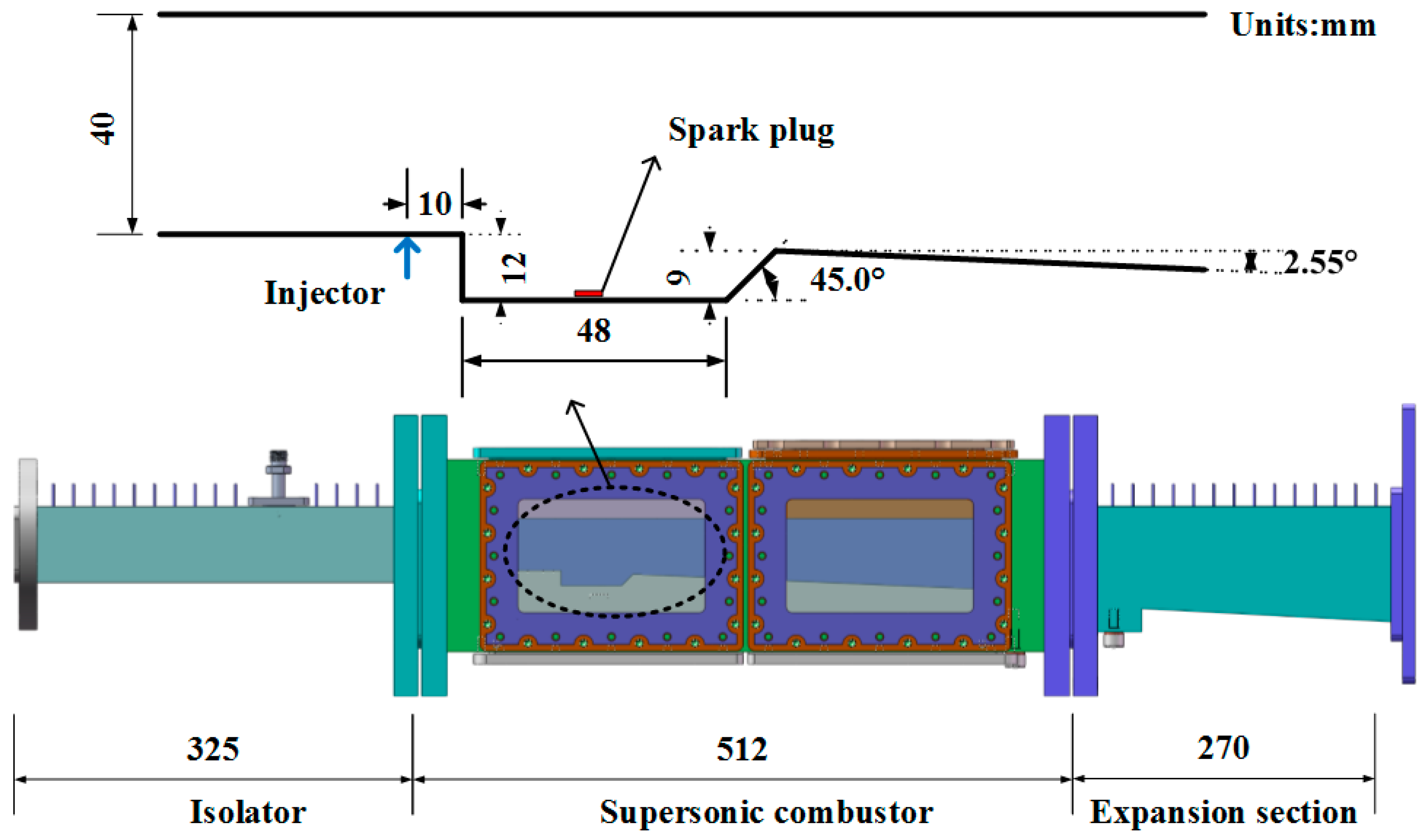
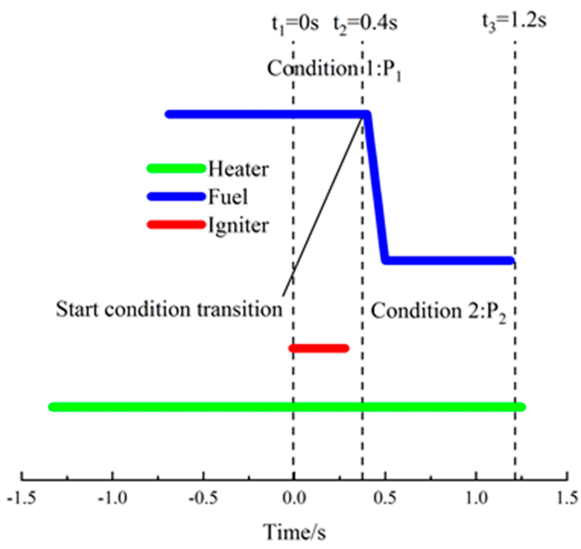
2.1. Experimental Setup

The experiments were carried out on a direct-connected supersonic combustion test device with a mass flow rate of 1 kg/s. The configuration of the supersonic combustion test device and the combustor is shown in Figure 1. Alcohol, O2, and air were burned in an air heater, thereby producing a high-enthalpy gas with a stagnation temperature of 1486 K and a stagnation pressure of 1.6 MPa. Through a Ma = 2.52 Laval nozzle, the gas was accelerated to a supersonic state to simulate the entrance flow of a scramjet when the flight condition is Mach 5.5 and the flight altitude is 25 km. The length, width, and height of the isolator were 325, 50, and 40 mm, respectively. The isolator was connected to the combustor and air heater. An expansion section with a length of 270 mm was connected to the combustor.
The length, width, and height of the combustor were 512, 40, and 50 mm respectively. The top wall and the bottom wall upstream of the cavity were both horizontal. The rear-wall diverged at a constant angle of 2.55°. The cavity with a depth of 12 mm and a bottom length of 48 mm was installed at the bottom wall of the combustor. The rear part of the cavity was a 45° ramp. A spark plug (the red mark) with an energy storage capacity of 5 J and a frequency of 50 Hz installed at the center of the bottom of the cavity was used to complete the ignition. The injector with a diameter of 2.0 mm (the blue mark) was arranged along the centerline of the bottom wall, 10 mm away from the leading edge of the downstream cavity. C2H4 at room temperature with a purity of 99.9% was adopted as the fuel in all the experiments. The study of condition transition mainly focused on adjusting the injection pressure. A fuel supply system that could dramatically change the injection pressure was adopted to simulate the condition transition of the scramjet. Figure 2 depicts a typical time sequence of the experiment. The time when ignition starts was considered 0 s. The time when the condition transition starts was 0.4 s, and the fuel supply system was stopped at 1.2 s. For convenience describing the experimental process, the injection pressures before and after condition transition are referred to as P1 and P2, respectively. Similarly, the states of stable combustion under these two conditions are named condition 1 and condition 2, respectively.
A high-speed camera (Photron SA-X2) was used to directly record flame chemiluminescence during the process of condition transition. The number of frames per second was set to 20,000, and the exposure time was 1/20,670 s. A pressure scanner containing 16 measurement channels with a sampling frequency of 100 Hz was used to measure and record the static pressure on the bottom wall of the combustor. The measurement range of the pressure scanner was 0–100 psi, and the uncertainty was 0.5% FS. The injection pressure before the injector was measured by a pressure transducer. The measuring range and the accuracy of the pressure transducer were 0–10 MPa and 0.1%.

2.2. Computational Setup

Mass, momentum, and energy conservation equations govern the combustion characteristics of ethylene in the combustor. The k-ω shear stress transport (SST) turbulence model was adopted in the numerical simulations. The equations were solved by a density-based double precision solver. The combustion process was simulated by the finite-rate/no TCI model and one-step ethylene-air chemical reaction mechanism [40]. The second-order upwind scheme was adopted to discretize the turbulent kinetic energy, specific dissipation rate, and energy equations in space.

3. Results and Discussion

In this study, transient chemiluminescence images were captured by high-speed photography, and the wall static pressure was recorded by a pressure scanner. The time-averaged image was obtained through average calculation of the images over a continuous period of time. Based on the analysis of the flame and wall pressure during the whole condition transition with different injection pressure drops, the characteristics of the combustion modes were analyzed in detail. In this section, the combustion modes after the condition transition are discussed in the first part, and the characteristics of stable combustion modes during the transition process are investigated in the second part.

3.1. Combustion Modes

The specific data of all the experimental cases are shown in Table 1. To ensure successful ignition and stable combustion, P1 was fixed at 3.65 MPa during all the experiments. However, it was inevitable that the actual injection pressure would drift slightly, but this drift was within the acceptable limits. To reveal the effect of the pressure drop on the combustion modes after the condition transition, P2 in the experiments was gradually reduced.
Three kinds of combustion modes were observed with different injection pressure drops. When the pressure drop was relatively small, the flame could be maintained and a stable combustion could be achieved under condition 2. The time-averaged flames during stable combustion before and after the condition transition for cases 1, 2, and 3 are displayed in Figure 3. The time-averaged image was averaged based on 1000 consecutive images captured by the high-speed camera during stable combustion, and the duration of each time-averaged flame was 50 ms. In addition, a white outline was added for clear identification of the flame boundary. As shown in Figure 3, the time-averaged flames for three cases under condition 1 were almost identical. The minor difference in P1 had little effect on the experimental results. The numerical results at condition 1 are shown in Figure 4. The mass fraction contours of H2O are shown in the spanwise plane and the temperature contours are shown in the bottom wall. It can be found that the mass fraction of H2O in spanwise plane increases along the X-axis, which is consistent with the flame image captured in experiment. In addition, chemical reactions mainly occurred in the centerline of the combustor, and few on the side walls of the combustor. By increasing the injection pressure drop, it can be seen that the area of the flame and the light intensity decreased significantly after the condition transition. Obviously, an increased pressure drop reduced the final equivalence ratio under condition 2, thus decreasing the intensity of the chemical reaction and the flame range. In addition, there were some differences in the flame distribution of stable combustion under different pressure drops. The flame filled the whole cavity in cases 1 and 2. However, the flame in case 3 was concentrated around the cavity ramp, and the flame range was small near the leading edge. The flame exhibited a typical cavity shear-layer-stabilized mode.
Figure 5 depicts the wall static pressure distribution along the bottom wall at stable combustion in two conditions for three cases. The wall pressure was uniform at each measuring position of the pressure when the combustion was stabilized in condition 1 for the three cases, which indicates that for these cases, P1 had no influence on the results in this study. Although the wall pressure was different for each of the three cases during condition 2, the distribution trend of the wall pressure in the combustor was consistent when the combustion was stable. The wall pressure increased along the combustor and then decreased when it reached the peak value. Increasing the injection pressure drop caused the pressure in the combustor to decrease obviously after the condition transition. This was mainly due to the decrease in the equivalence ratio, which reduced the intensity of combustion. Furthermore, the wall pressure near the cavity had a more pronounced decrease than that downstream of the cavity. The position where the pressure peak appears moves downstream as P2 decreases. This indicates that the increase in the injection pressure drop caused the decrease in combustion intensity in the cavity to be more obvious than that in the downstream area.
The stable combustion mode after the condition transition and the effect of the injection pressure drop were discussed above. Upon increasing the pressure drop further, a clear local extinction and reignition phenomenon was found during condition 2 near the lean blowout limits. Figure 6 shows typical transient flame images under the mode of combustion oscillation for case 4. Because the flame image captured in this case was too dark to distinguish clearly, the images were processed in pseudocolor for clearer display. The interval between two adjacent images was 0.2 ms. Although the flame always existed in the combustor, it was evident that the shape of the flame abruptly changed. The flame in the cavity was mainly concentrated near the ramp, while the downstream flame was close to the bottom wall of the combustor. As shown in images 4 and 13 in Figure 5, the flame started to break into two separate parts, and then an obvious local flame extinction phenomenon could be found downstream of the ramp. However, the local extinction in this condition was not persistent, and these extinction areas were reignited with the propagation of the cavity flame. Since the equivalence ratio was relatively low after the condition transition, the chemical reactions were in a weak reaction state. The flame in the weak reaction state was extremely unstable and prone to partial extinction. However, some high-temperature free radicals in the cavity re-ignited the blowout area, resulting in an intermittent extinction and reignition process. This unstable combustion phenomenon accompanied by local extinction and reignition is called the combustion oscillation mode in this paper.
To quantitatively compare these two combustion modes under condition 2, the flame light intensities for cases 1–4 were calculated and normalized. The light intensity was calculated by integrating the pixels in the image captured by high-speed photography, and the average value of the light intensity in condition 1 for cases 1–3 was used to normalize the light intensity profiles. Figure 6 shows the normalized light intensity under different injection pressure drops after condition transitions. As shown in Figure 7a, the normalized light intensity oscillates in a certain range with time for cases 1–3. However, the light intensity for case 4 varied more significantly, and the light intensity in some images was even close to 0. Furthermore, the statistical results in Figure 7b show that the distribution of light intensity was similar for cases 1–3, indicating that the combustion mode for these three cases was coincident. For the combustion oscillation mode, the probability density profiles of light intensity for case 4 are obviously different from those for the cases under stable combustion modes.
With a further increase in the injection pressure drop, an obvious flame blowout phenomenon could be observed during the condition transition. When the injection pressure corresponding to condition 2 became stable again, the flame in the cavity was completely extinguished. Figure 8 depicts the distribution of the wall pressure at different times for case 5. The wall pressure decreased rapidly with time during the condition transition and then remained almost the same.
To obtain a comprehensive understanding of the injection pressure drop for the combustion modes after the condition transition, several cases for combustion oscillation and flame blowout were carried out with the same method. All the results are summarized in Figure 9.
In other words, with the increase in the injection pressure drop, three combustion modes appear in turn after the condition transition. These modes include stable combustion mode, combustion oscillation mode, and flame blowout mode. During stable combustion, the range of the flame, light intensity, and combustion intensity decrease with increasing injection pressure drop. The flame in the combustion oscillation mode is near the blowout limit, and this accompanies intermittent local extinction and reignition phenomena.

3.2. Transition Process of the Stable Combustion Mode

The three combustion modes that appear after the condition transition are discussed in the last section. It was necessary to analyze the flame development characteristics during the transition process under the stable combustion mode.
In the experiment, approximately 20–200 ms was required to finish the switching process from condition 1 to condition 2. However, the flame images of the whole transition process could not be displayed at the same time. For the convenience of demonstrating the flame propagation characteristics during the switching process, a time-averaged calculation of the flame image within 75 ms was carried out. Figure 10 illustrates the time-averaged flame within different time periods from 0.325–0.700 s for cases 1–3. The time-averaged image between 0.325 and 0.400 s shows almost no difference for cases 1–3, which reveals that the initial combustion status in condition 1 can be considered consistent. As the injection pressure decreased, the flames exhibited combined shear-layer- and/recirculation-stabilized modes at all times for cases 1 and 2. By contrast, although the combustion for case 3 was always stable, it should be noted that the flame area in the cavity was significantly reduced, and the flame structure also changed obviously. According to the definition of the flame-stabilized modes [12], the stable combustion mode gradually shifted from the combined shear-layer/recirculation-stabilized mode to the cavity shear-layer stabilized mode for case 3.
The wall pressure profiles during condition transition are depicted in Figure 11. As shown in Figure 11a, due to the smaller injection pressure drop for case 1, the change in the equivalence ratio during the process of condition transition was relatively small. The wall pressure exhibited little change; a minor decrease was only observed near the cavity. With the increase in the injection pressure drop to 0.43 MPa, the wall pressure in the combustor exhibited a palpable decrease in the transition process and then remained almost the same for case 2. The wall pressure in the combustor decreased more rapidly with time for case 3. Furthermore, a clear difference is evident in the profiles of the wall pressure. The profiles of the wall pressure at 0.43, 0.48, and 0.53 s are consistent, and they all increase and then decrease along the X-axis. However, as the flame-stabilized mode switched from the combined shear-layer/recirculation-stabilized mode to the cavity shear-layer stabilized mode, the distribution of the wall pressure changed accordingly. The profiles of the wall pressure at 0.58 s and 0.63 s increase first and then remain almost the same. Obviously, the main chemical reaction zone gradually moved downstream when the stabilized mode of the flame changed, resulting in a variation in the wall pressure distribution.
To describe the development trend in the flame during the transition process, Figure 12 depicts the normalized integrated light intensity in the combustor with different pressure drops. The light intensity profiles were normalized with the same method mentioned above. As shown in Figure 12a, the light intensity of the flame decreased gradually with decreasing injection pressure during the transition process in each case, which indicated that the combustion intensity gradually decreased. Obviously, the fuel entering the combustor decreased with time during the transition process, resulting in a gradual weakening of the intensity of the chemical reactions. There was a sudden drop before the light intensity stabilizes again, mainly due to a slight decrease in the injection pressure before it became stable.
Locally weighted scatterplot smoothing (LW smoothing) is a useful method for smoothing experiment data [41]. The normalized light intensity with LW smoothing is depicted in Figure 12b. The three horizontal black dotted lines are the average normalized light intensity in each case during stable combustion for condition 2. The initial time of stable combustion under condition 2 was the first time that the LW smoothing of the normalized light intensity was equal to the average light intensity after the sudden decrease in light intensity. The green circles mark the initial times when the combustion stabilized again for the three cases, which are 0.422, 0.525, and 0.610 s. It can be noted that the time required to complete the transition process increased when the injection pressure drop increased.

4. Conclusions

In this paper, the combustion modes and unsteady characteristics during the condition transition were experimentally investigated with a direct-connected supersonic combustion test device. The simulated flight condition was Mach 5.5 and flight altitude was 25 km. A dramatic fuel supply system was adopted to simulate the condition transition in a scramjet combustor, leading to a sharp step in the global equivalence ratio. By comparing the flame characteristics and wall pressure profiles during the condition transition, the main conclusions can be drawn as follows:
(1)
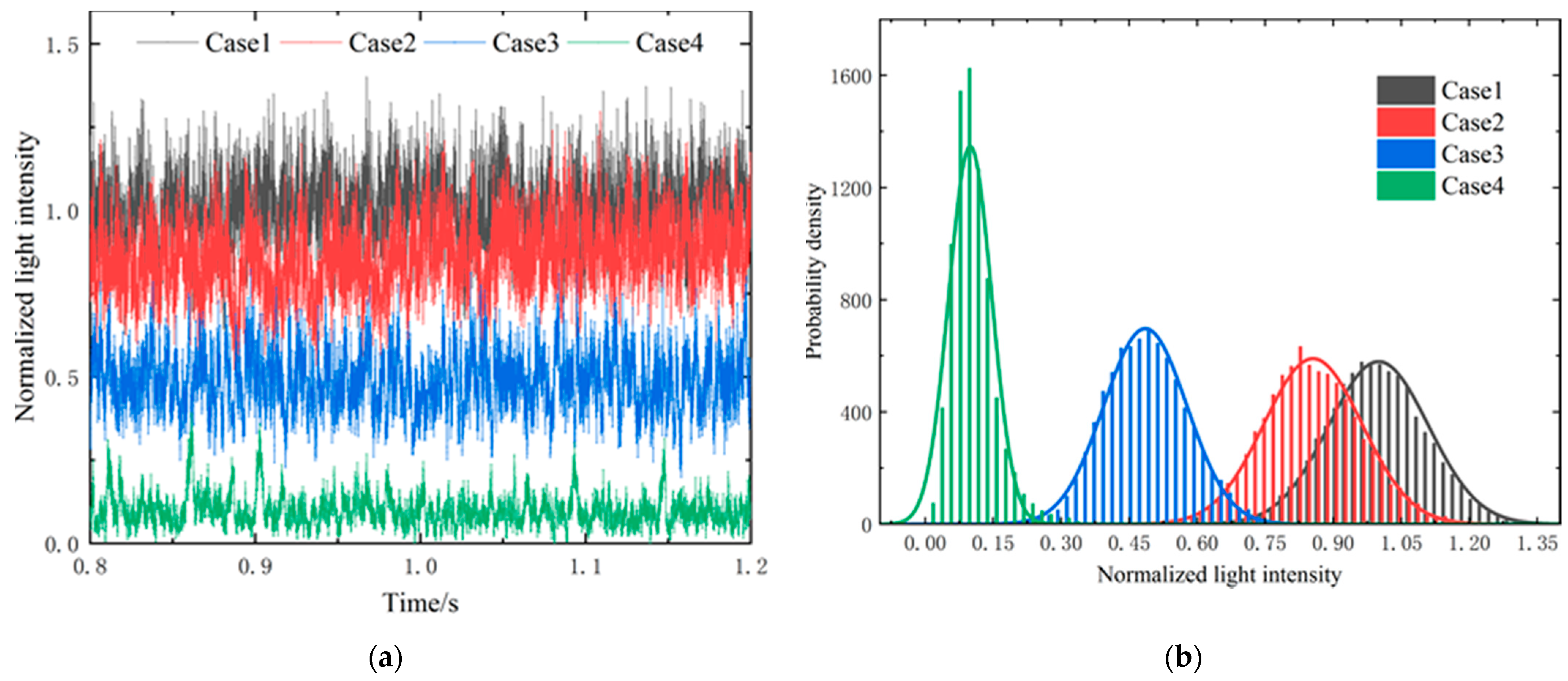
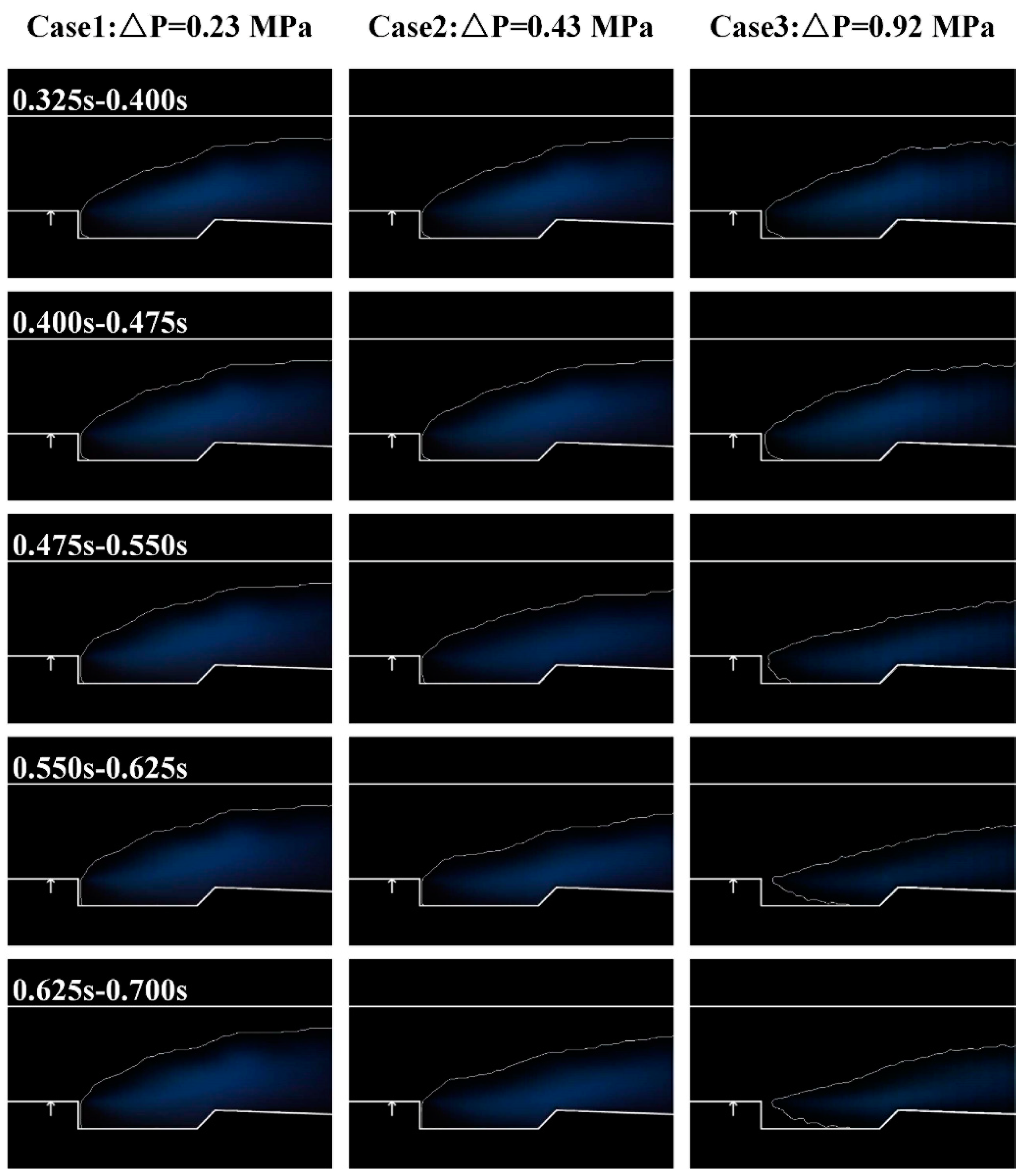
With the increase in the injection pressure drop, three combustion modes appear during the condition transition of a scramjet, namely stable combustion mode, combustion oscillation mode, and flame blowout mode. When the injection pressure drop increases during the stable combustion modes, the area of the flame and the light intensity decrease gradually, and the wall pressure decreases accordingly after the condition transition.
(2)
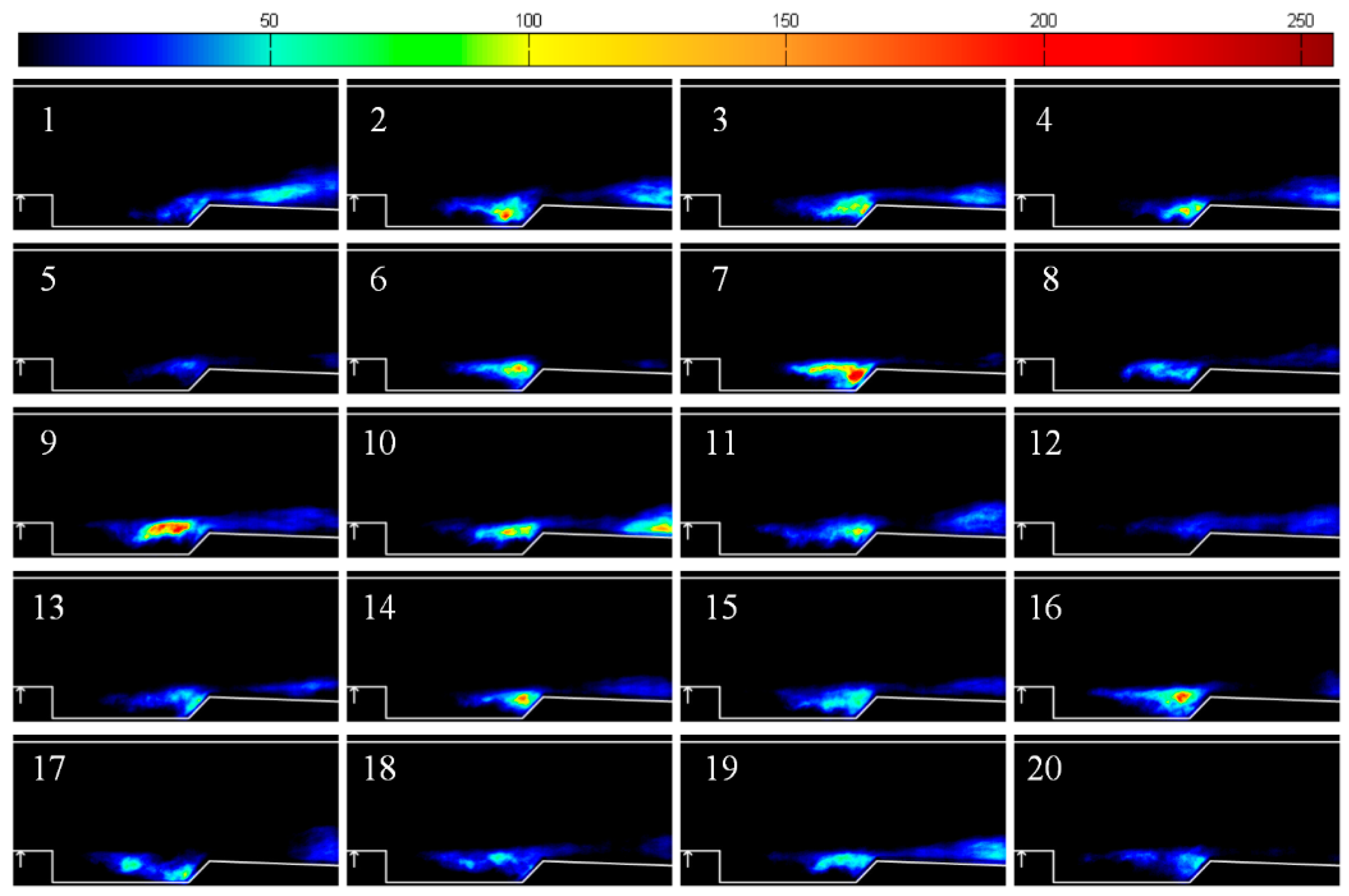
An obvious intermittent local flame extinction phenomenon can be observed downstream of the cavity near the blowout limits. This combustion oscillation mode is accompanied by alternate local extinction and reignition phenomena. With a further increase in the injection pressure drop, an obvious flame blowout phenomenon occurs during the condition transition.
(3)
In the stable combustion modes, the combustion intensity deceases gradually as the injection pressure decreases during the transition process. When the injection pressure drop is relatively high, the flame-stabilized mode changes during the transition process, accompanied by a change in the distribution of wall pressure.
The combustion modes after the condition transition and the switching characteristics of two stable combustion modes are of great significance for guiding the design of the condition transition in a scramjet. Furthermore, it is valuable to determine the adjustment range of injection to ensure the stabilized flame during the transition process. In the future research, it is necessary to investigate the characteristics of flame blowout at low equivalence ratio, which is beneficial to enrich the research results of the condition transition of scramjets.

Author Contributions

Conceptualization, C.L. and Y.P.; methodology, C.L. and Y.P.; software, D.J.; validation, C.L., D.J., Y.P., and K.Y.; formal analysis, D.J.; investigation, C.L.; resources, C.L.; data curation, K.Y.; writing—original draft preparation, D.J.; writing—review and editing, N.W.; visualization, D.J.; supervision, Y.P.; project administration, C.L.; funding acquisition, C.L. All authors have read and agreed to the published version of the manuscript.

Funding

This research was funded by National Natural Science Foundation of China, grant number 12002373.

Institutional Review Board Statement

Not applicable.

Informed Consent Statement

Not applicable.

Data Availability Statement

Data are contained within article.

Conflicts of Interest

The authors declare no conflict of interest.

References

  1. Neill, S.M.; Pesyridis, A. Modeling of Supersonic Combustion Systems for Sustained Hypersonic Flight. Energies 2017, 10, 1900. [Google Scholar] [CrossRef] [Green Version]
  2. Choubey, G.; Pandey, K.M.; Maji, A.; Deshamukhya, T. A brief review on the recent advances in scramjet engine. In Proceedings of the International Conference on Functional Materials, Characterization, Solid State Physics, Power, Thermal and Combustion Energy, Andhra Pradesh, India, 7–8 April 2017; Malla, S.G., Sanjay, S.D., Khan, M.P., Eds.; AIP Conference Proceedings: Melville, NY, USA, 2017; Volume 1859. [Google Scholar]
  3. Urzay, J. Supersonic Combustion in Air-Breathing Propulsion Systems for Hypersonic Flight. In Annual Review of Fluid Mechanics; Davis, S.H., Moin, P., Eds.; Annual Review of Fluid Mechanics: Palo Alto, CA, USA, 2018; Volume 50, pp. 593–627. [Google Scholar]
  4. Jeong, S.-M.; Choi, J.-Y. Combined Diagnostic Analysis of Dynamic Combustion Characteristics in a Scramjet Engine. Energies 2020, 13, 4029. [Google Scholar] [CrossRef]
  5. Wang, Z.; Wang, H.; Sun, M. Review of cavity-stabilized combustion for scramjet applications. Proc. Inst. Mech. Eng. Part G J. Aerosp. Eng. 2014, 228, 2718–2735. [Google Scholar] [CrossRef]
  6. Kummitha, O.R.; Pandey, K.M.; Gupta, R. Optimization of scramjet performance with different fuel injection techniques and flame holder cavities. Acta Astronaut. 2018, 152, 908–919. [Google Scholar] [CrossRef]
  7. Tuncer, O. Combustion in a Ramjet Combustor with Cavity Flame Holder. In Proceedings of the 48th AIAA Aerospace Sciences Meeting Including the New Horizons Forum and Aerospace Exposition 2010, Orlando, FL, USA, 4–7 January 2010; Volume 20, pp. 18086–18097. [Google Scholar]
  8. Liu, C.; Sun, M.; Wang, H.; Yang, L.; An, B.; Pan, Y. Ignition and flame stabilization characteristics in an ethylene-fueled scramjet combustor. Aerosp. Sci. Technol. 2020, 106, 106186. [Google Scholar] [CrossRef]
  9. Micka, D.J.; Driscoll, J.F. Combustion characteristics of a dual-mode scramjet combustor with cavity flameholder. Proc. Combust. Inst. 2009, 32, 2397–2404. [Google Scholar] [CrossRef]
  10. Wang, Y.; Wang, Z.; Sun, M.; Wang, H. Combustion stabilization modes in a hydrogen-fueled scramjet combustor at high stagnation temperature. Acta Astronaut. 2018, 152, 112–122. [Google Scholar] [CrossRef]
  11. Jialing, L.; Shunhua, Y.; Xiyao, W.; Hongbin, L. Analysis and Correlation of Flame Stability Limits in Supersonic Flow with Cavity Flameholder. In Proceedings of the 18th AIAA/3AF International Space Planes and Hypersonic Systems and Technologies Conference 2012, Tours, France, 24–28 September 2012; Volume 3, pp. 1691–1699. [Google Scholar]
  12. Wang, H.; Wang, Z.; Sun, M.; Wu, H. Combustion modes of hydrogen jet combustion in a cavity-based supersonic combustor. Int. J. Hydrogen Energy 2013, 38, 12078–12089. [Google Scholar] [CrossRef]
  13. Tian, Y.; Yang, S.; Le, J.; Su, T.; Yue, M.; Zhong, F.; Tian, X. Investigation of combustion and flame stabilization modes in a hydrogen fueled scramjet combustor. Int. J. Hydrogen Energy 2016, 41, 19218–19230. [Google Scholar] [CrossRef]
  14. Aguilera, C.; Yu, K.H. Scramjet to ramjet transition in a dual-mode combustor with fin-guided injection. Proc. Combust. Inst. 2017, 36, 2911–2918. [Google Scholar] [CrossRef]
  15. Li, J.; Wang, K.; Jiao, G.; Luo, J.; Song, W. Experimental Study on Mode Transition in a Dual-Mode Scramjet Combustor. Combust. Sci. Technol. 2020, 192, 852–870. [Google Scholar] [CrossRef]
  16. Ouyang, H.; Liu, W.; Sun, M. The large-amplitude combustion oscillation in a single-side expansion scramjet combustor. Acta Astronaut. 2015, 117, 90–98. [Google Scholar] [CrossRef]
  17. Sartor, F.; Mettot, C.; Bur, R.; Sipp, D. Unsteadiness in transonic shock-wave/boundary-layer interactions: Experimental investigation and global stability analysis. J. Fluid Mech. 2015, 781, 550–577. [Google Scholar] [CrossRef] [Green Version]
  18. Guiho, F.; Alizard, F.; Robinet, J.C. Instabilities in oblique shock wave/laminar boundary-layer interactions. J. Fluid Mech. 2016, 789, 1–35. [Google Scholar] [CrossRef] [Green Version]
  19. Lin, K.-C.; Jackson, K.; Behdadnia, R.; Jackson, T.A.; Ma, F.; Yang, V. Acoustic Characterization of an Ethylene-Fueled Scramjet Combustor with a Cavity Flameholder. J. Propuls. Power 2010, 26, 1161–1169. [Google Scholar] [CrossRef] [Green Version]
  20. Wang, Z.-g.; Sun, M.-b.; Wang, H.-b.; Yu, J.-f.; Liang, J.-h.; Zhuang, F.-c. Mixing-related low frequency oscillation of combustion in an ethylene-fueled supersonic combustor. Proc. Combust. Inst. 2015, 35, 2137–2144. [Google Scholar] [CrossRef]
  21. Wang, H.; Wang, Z.; Sun, M. Experimental study of oscillations in a scramjet combustor with cavity flameholders. Exp. Therm. Fluid Sci. 2013, 45, 259–263. [Google Scholar] [CrossRef]
  22. Wang, T.; Li, G.; Yang, Y.; Wang, Z.; Cai, Z.; Sun, M. Combustion modes periodical transition in a hydrogen-fueled scramjet combustor with rear-wall-expansion cavity flameholder. Int. J. Hydrogen Energy 2020, 45, 3209–3215. [Google Scholar] [CrossRef]
  23. Ouyang, H.; Liu, W.; Sun, M. Parametric study of combustion oscillation in a single-side expansion scramjet combustor. Acta Astronaut. 2016, 127, 603–613. [Google Scholar] [CrossRef]
  24. Ouyang, H.; Liu, W.; Sun, M. The influence of cavity parameters on the combustion oscillation in a single-side expansion scramjet combustor. Acta Astronaut. 2017, 137, 52–59. [Google Scholar] [CrossRef]
  25. Song, X.; Wang, H.; Sun, M.; Cai, Z.; Liu, C.; Yu, J. Mixing and combustion characteristics in a cavity-based supersonic combustor with different injection schemes. Acta Astronaut. 2019, 159, 584–592. [Google Scholar] [CrossRef]
  26. Tian, Y.; Yang, S.; Le, J.; Zhong, F.; Tian, X. Investigation of the effects of fuel injector locations on ignition and flame stabilization in a kerosene fueled scramjet combustor. Aerosp. Sci. Technol. 2017, 70, 310–316. [Google Scholar] [CrossRef]
  27. Kirik, J.W.; Goyne, C.P.; McDaniel, J.C.; Rockwell, R.D. Aerodynamics of Lean Blowout in a Premixed Dual-Mode Scramjet. J. Propuls. Power 2018, 34, 819–822. [Google Scholar] [CrossRef]
  28. Kirik, J.W.; Goyne, C.P.; McDaniel, J.C.; Rockwell, R.D.; Cantu, L.M.L.; Gallo, E.C.A.; Cutler, A.D. Aerodynamic Characterization of a Cavity Flameholder in a Premixed Dual-Mode Scramjet. J. Propuls. Power 2018, 34, 739–749. [Google Scholar] [CrossRef]
  29. Nilsson, T.; Carlsson, H.; Yu, R.; Bai, X.-S. Structures of turbulent premixed flames in the high Karlovitz number regime—DNS analysis. Fuel 2018, 216, 627–638. [Google Scholar] [CrossRef]
  30. Di Sarli, V.; Di Benedetto, A.; Russo, G. Large Eddy Simulation of transient premixed flame-vortex interactions in gas explosions. Chem. Eng. Sci. 2012, 71, 539–551. [Google Scholar] [CrossRef]
  31. Savard, B.; Bobbitt, B.; Blanquart, G. Structure of a high Karlovitz n-C7H16 premixed turbulent flame. Proc. Combust. Inst. 2015, 35, 1377–1384. [Google Scholar] [CrossRef] [Green Version]
  32. Liu, C.; Wang, Z.; Sun, M.; Wang, H.; Li, P. Characteristics of a Cavity-Stabilized Hydrogen Jet Flame in a Model Scramjet Combustor. AIAA J. 2019, 57, 1–12. [Google Scholar] [CrossRef]
  33. Rasmussen, C.C.; Driscoll, J.F.; Hsu, K.Y.; Donbar, J.M.; Gruber, M.R.; Carter, C.D. Stability limits of cavity-stabilized flames in supersonic flow. Proc. Combust. Inst. 2005, 30, 2825–2833. [Google Scholar] [CrossRef]
  34. Wang, Y.; Song, W. Experimental investigation of influence factors on flame holding in a supersonic combustor. Aerosp. Sci. Technol. 2019, 85, 180–186. [Google Scholar] [CrossRef]
  35. Rasmussen, C.; Driscoll, J. Blowout Limits of Flames in High-Speed Airflows: Critical Damkohler Number. In Proceedings of the 44th AIAA/ASME/SAE/ASEE Joint Propulsion Conference & Exhibit (Joint Propulsion Conferences), Hartford, CT, USA, 21–23 July 2008; American Institute of Aeronautics and Astronautics: Reston, VA, USA, 2008. [Google Scholar]
  36. Zhang, T.; Wang, J.; Qi, L.; Fan, X.; Zhang, P. Blowout Limits of Cavity-Stabilized Flame of Supercritical Kerosene in Supersonic Combustors. J. Propuls. Power 2014, 30, 1161–1166. [Google Scholar] [CrossRef] [Green Version]
  37. Zhu, S.; Xu, X.; Ji, P. Flame Stabilization and Propagation in Dual-Mode Scramjet with Staged-Strut Injectors. AIAA J. 2017, 55, 171–179. [Google Scholar] [CrossRef]
  38. Zhu, S.H.; Xu, X. Experimental Study on Flame Transition in a Two-Stage Struts Dual-Mode Scramjet. J. Aerosp. Eng. 2017, 30. [Google Scholar] [CrossRef]
  39. Xue, R.; Xu, M.; Bai, C.; Weng, C.; Xu, C. Study on transient process of mode transition in a scramjet combustor with pilot hydrogen. Int. J. Energy Res. 2018, 42, 2481–2493. [Google Scholar] [CrossRef]
  40. Huang, W.; Li, L.-q.; Yan, L.; Liao, L. Numerical exploration of mixing and, combustion in a dual-mode combustor with backward-facing steps. Acta Astronaut. 2016, 127, 572–578. [Google Scholar] [CrossRef] [Green Version]
  41. Smolik, M.; Skala, V.; Nedved, O. A Comparative Study of LOWESS and RBF Approximations for Visualization. In Lecture Notes in Computer Science, Proceedings of the Computational Science and Its Applications—ICCSA 2016, pt. II, Beijing, China, 4–7 July 2016; Gervasi, O., Murgante, B., Misra, S., Rocha, A., Torre, C.M., Tanier, D., Apduhan, B.O., Stankova, E., Wang, S., Eds.; Springer: Cham, Switzerland, 2016; Volume 9787, pp. 405–419. [Google Scholar]
Figure 1. Configuration of the supersonic combustion test device and the combustor.
Energies 14 02522 g001
Figure 2. A typical time sequence of the experiment.
Energies 14 02522 g002
Figure 3. Comparison of the time-averaged flame during stable combustion before and after the condition transition (Upper images: condition 1; Lower images: condition 2).
Energies 14 02522 g003
Figure 4. Mass fraction of H2O and temperature contours in condition 1.
Energies 14 02522 g004
Figure 5. Distribution of the wall pressure during stable combustion before and after the condition transition.
Energies 14 02522 g005
Figure 6. Images of typical transient flames under the mode of combustion oscillation for case 4 (△t = 0.2 ms).
Energies 14 02522 g006
Figure 7. Normalized light intensity under different injection pressure drops after the condition transition. (a) Profiles of the normalized light intensities. (b) Probability densities of the normalized light intensities.
Energies 14 02522 g007
Figure 8. Distribution of the wall pressure at different times when the flame blowout.
Energies 14 02522 g008
Figure 9. Schematic diagram of the combustion modes under different injection pressure drops.
Energies 14 02522 g009
Figure 10. Time-averaged flame within different time periods.
Energies 14 02522 g010
Figure 11. Change in the wall pressure profiles with time during condition transition. (a) Case 1. (b) Case 2. (c) Case 3.
Energies 14 02522 g011
Figure 12. Light intensity profiles in the combustor with injection pressure drops of 0.23, 0.43, and 0.92 MPa. (a) Normalized light intensity. (b) Locally weighted smoothing of the normalized light intensity.
Energies 14 02522 g012
Table 1. Specific information of all experiment cases.
Case No.P1 (MPa)P2 (MPa)Pressure Drop (MPa)Equivalence RatioFlame Structure
13.673.440.230.244→0.217stabilization
23.673.240.430.244→0.205
33.692.770.920.244→0.180
43.672.321.350.244→0.160oscillation
53.642.241.420.244→0.153blowout
Publisher’s Note: MDPI stays neutral with regard to jurisdictional claims in published maps and institutional affiliations.

