Article

Critical Buckling Generation of TCA Benchmark by the B1 Theory-Augmented Monte Carlo Calculation and Estimation of Uncertainties

Korea Atomic Energy Research Institute, Daejeon 34057, Korea
*
Author to whom correspondence should be addressed.
Energies 2021, 14(9), 2578; https://doi.org/10.3390/en14092578
Submission received: 5 April 2021 / Revised: 27 April 2021 / Accepted: 28 April 2021 / Published: 30 April 2021
(This article belongs to the Special Issue Computational Techniques of Nuclear Reactor Physics)

Abstract

:
The Korea Atomic Energy Research Institute (KAERI) has developed the DeCART2D 2-dimensional (2D) method of characteristics (MOC) transport code and the MASTER nodal diffusion code and has established its own two-step procedure. For design code licensing, KAERI prepared a critical experiment on the verification and validation (V&V) of the DeCART2D code. DeCART2D is able to perform the MOC calculation only for 2D nuclear fuel systems, such as the fuel assembly. Therefore, critical buckling in the vertical direction is essential for comparison between the results of experiments and DeCART2D. In this study, the B1 theory-augmented Monte Carlo (MC) method was adopted for the generation of critical buckling. To examine critical buckling using the B1 theory-augmented MC method, TCA critical experiment benchmark problems were considered. Based on the TCA benchmark results, it was confirmed that the DeCART2D code with the newly-generated critical buckling predicts the criticality very well. In addition, the critical buckling generated by the B1 theory-augmented MC method was bound to uncertainties. Therefore, utilizing basic equations (e.g., SNU S/U formulation) linking input uncertainties to output uncertainties, a new formulation to estimate the uncertainties of the newly generated critical buckling was derived. This was then used to compute the uncertainties of the critical buckling for a TCA critical experiment, under the assumption that nuclear cross-section data have uncertainties.

1. Introduction

In nuclear design and analysis, a conventional two-step procedure, involving assembly-wise lattice transport and whole core nodal calculations, has been widely and efficiently utilized. This two-step procedure involves unavoidable approximations, such as energy group condensation and assembly-wise homogenization. Energy group condensation and assembly-wise homogenization can be used to establish few group constants (FGCs) from continuous or ultra-fine energy group cross sections and to simplify cell-wise geometric information data. These assembly-wise FGCs are utilized to conduct whole-core nodal calculations. Moreover, a correction of the leakage spectrum (e.g., the B1 method) is applied to the whole-core calculations for improved accuracy. As a part of the localization of nuclear reactor development in Korea, the Korea Atomic Energy Research Institute (KAERI) developed the DeCART2D [1] 2-dimensional (2D) method of characteristics (MOC) transport code and the MASTER [2] nodal diffusion code and established its own two-step procedure. The DeCART2D code generates assembly-wise FGCs and pin-to-box factors (i.e., pin-wise power distribution), which are used in the MASTER nodal whole-core calculations. To apply the DeCART2D/MASTER code system to nuclear design and analyses, KAERI is now in the progress of licensing the nuclear design analysis code system. Accordingly, KAERI prepared a critical experiment for verification and validation (V&V) of the DeCART2D code. The main purpose of this critical experiment was to check whether the DeCART2D code could accurately provide the pin-to-box factor.
The DeCART2D code can perform the MOC calculation only for a 2D based nuclear system. Therefore, to compare the pin-to-box factors from the critical experiment with those yielded by the DeCART2D code, critical buckling and diffusion coefficients in the vertical direction are necessary. In a critical experiment with a finite cylinder system, vertical buckling generally can be obtained using the extrapolation distance from the activation measurements and the active height of the core.
As an alternative way to obtain the vertical critical buckling, the Monte Carlo (MC) method [3,4,5] is an attractive approach because it provides highly accurate and efficient solutions in the field of nuclear reactor design and analysis. Yamamoto [6,7] developed the heterogeneous B1 method by introducing a complex-value weight into MC particle transport simulations. The complex-value-weight-based heterogeneous B1 method can provide directional diffusion coefficients and critical buckling based on leakage-corrected keff-eigenvalue calculations. Meanwhile, the B1 theory-augmented MC method can be used to generate fuel pin cell or fuel assembly FA-homogenized few-group diffusion theory constants (FGCs) in the same manner as deterministic-based diffusion theory computations of power reactors [8,9,10,11]. In previous studies [8,9,10], we presented the B1 theory-augmented MC method for generating homogenized FGCs including diffusion coefficients, critical buckling, and migration area, and verified the results through a nuclear core design analysis of Yonggwang Nuclear Unit 4.
In general, a result yielded by an MC calculation always includes stochastic uncertainty, because the MC method uses a finite number of samples (e.g., neutron particles) through the use of random numbers. Accordingly, the critical buckling by the B1 theory-augmented MC method may be bound partly to the statistical uncertainties inherent in the MC method, and partly to the uncertainties of the input data such as the cross section, geometric data, and material composition. In previous studies, we introduced basic mathematical equations aimed at quantifying the uncertainties of FGCs over burnup. These basic mathematical equations from the so-called ‘SNU S/U formulation’ [12] can be utilized to link input uncertainties to output uncertainties. In the same manner as the uncertainties of FGCs, the SNU S/U formulation can be easily adapted to quantify the uncertainties of the critical buckling generated by the B1 theory-augmented MC method.
The purpose of this study was to generate critical buckling, based on the B1 theory-augmented MC method, for DeCART2D calculations and to quantify the uncertainties of the critical buckling due to stochastic uncertainties and the uncertainties of the input parameters (e.g., cross section, geometric data, and material composition). In this study, the critical buckling for the tank-type critical assembly (TCA) benchmark problem [13,14], which provides the measured values for the critical water level and extrapolation for each case distance, is generated using the B1 theory-augmented MC method. Furthermore, the uncertainties of the critical buckling are estimated using the SNU S/U formulation.
Section 2 briefly describes the generation of the critical buckling using the B1 theory-augmented MC method and the direct fitting method. Section 3 explains how to quantify the uncertainties of the critical buckling via the B1 theory-augmented MC method using the SNU S/U formulation. In Section 4, we apply the newly implemented uncertainty quantification capability to perform the TCA critical facility benchmark for the generation of the critical buckling. In this section, we present the uncertainties in the critical buckling that occur due to the uncertainties in nuclear cross section data and the tolerance of the geometric and material composition data. The conclusions and summations are presented in Section 5.

2. Generation of Critical Buckling

2.1. Critical Buckling Generation Using the B1 Theory-Augmented MC Method

This section briefly explains how to obtain the critical buckling via the B1 theory-augmented MC method. The conventional multi-group B1 equations in a fine group representation are as below:
Σ t , g ϕ g ± i B J g = g Σ g g 0 ϕ g + χ g ± i B ϕ g + 3 α g ( B ) Σ t , g J g = 3 g Σ g g 1 J g , where   α g ( B ) = { 1 3 x 2 ( arctan ( x ) x arctan ( x ) ) for   x 2 = ( B Σ ) 2 > 0 1 3 x 2 ( ln ( ( 1 + x ) / ( 1 x ) ) ln ( ( 1 + x ) / ( 1 x ) ) 2 x ) for   x 2 = ( B Σ ) 2 > 0 .
Here, g and g′ refer to the energy group. Σ t , g and Σ f , g are the macroscopic total and fission cross-section, respectively. Σ g g n (n = 0,1) indicates the zero and first-order moment of the double differential scattering cross-section. The other notations are standard and ϕ g is normalized to satisfy k = ν Σ f , g ϕ g , where k is the multiplication factor. The macroscopic cross-section is expressed by
Σ α , g = 1 φ g j , m N j m r α , g , j m ,
where φ g is the infinite medium spectrum (IMS). N j m and r α , g , j m indicate the number density and α -type microscopic reaction rate for nuclide j in region m. The microscopic reaction rate and IMS are calculated using the microscopic cross-section or angular neutron flux, as given below:
φ g = V m Δ E g 4 π ϕ ( r , E , Ω ) d Ω d E d r ,
r α , g , j m = V m Δ E g 4 π σ α , j ( E ) ϕ ( r , E , Ω ) d Ω d E d r ,
where Vm is the volume of the region m, whereas Δ E g is the energy interval of group g neutrons. A conventional MC code tallies the microscopic reaction rates and IMS for the total, fission, and scattering macroscopic cross section calculations using the track length and collision estimator method. Using the macroscopic cross sections, the multi-group B1 equations, Equation (1), are solved through iterative adjustments of B2 until the corresponding k = 1. The solution ϕ g and B2 satisfying k = 1 are the so-called critical spectrum (CS), ϕ g B , and the critical buckling, B c .

2.2. Critical Buckling Generation Using the Fitted Cosine Function

Based on an experiment, the axial buckling [15] for a critical condition can be calculated using the extrapolated length from its activation measurements. In a finite cylinder reactor, normalized flux distributions for the vertical axis can be described well using a sinusoid with the extrapolated length. If a finite cylinder reactor has an extrapolated height H′ and is centered about z = 0, the vertical flux distribution and geometric buckling can be written as follows:
ϕ ( z ) = α cos ( π z H ) ,
B z 2 = ( π H ) 2 ,
H = H + λ z ,
where H is the height of the core in a finite cylinder reactor and λ z is the extrapolated length or distance. In the same manner as the experiment, it is possible to obtain the axial critical buckling from the axial flux distribution, ϕ M C , which is calculated using the 3-dimensional MC calculation for the critical condition. The vertical extrapolation length can be determined through a fitting procedure for a cosine function. The fitting method is applied to minimize the sum of the squares of the difference between ϕ M C and the value ( ϕ F I T ) from the fitted cosine function at the same height position. An R-squared (R2) value is used to quantify how close the MC-calculated values are to the fitted regression cosine function. Equation (8) shows the common definition of R2 between ϕ M C and ϕ F I T .
R 2 = 1 i = 1 N ( ϕ M C i ϕ F I T i ) 2 i = 1 N ( ϕ M C i ϕ M C i ¯ ) 2   where   ϕ M C i ¯ = 1 N i = 1 N ϕ M C i ,
where N and i indicate the total number of mesh tallies and the mesh index number, respectively.

3. Propagation of Uncertainties in Critical Buckling Generation

3.1. Estimation of the Critical Buckling Uncertainties Using the SNU S/U Formulation

Figure 1 summarizes the procedure used to obtain the critical buckling in the B1 theory-augmented MC method. The whole procedure is divided into three steps. The uncertainty of the critical buckling is calculated step-by-step, because the outputs of any given step become inputs of the next step. The basic equations linking the uncertainties of the inputs to those of the outputs were derived in a previous study [12]. Suppose that Q represents the output parameters at any given step and ui (i = 1, 2, , I) is a set of uncertain input data for Q calculation. Formally, Q may be written as follows:
Q = Q ( u 1 , u 2 , , u I ) ,
Through the deviation of the SNU S/U formulation, linking uncertainties using the 1st order Taylor expansions [8], the uncertainty of Q is expressed by
σ 2 ( Q ) = σ S T A T S 2 ( Q ) + σ I N P 2 ( Q ) ,
σ S T A T S 2 ( Q ) = lim K 1 K 1 κ = 1 K ( Q κ Q κ ) 2 ,
σ I N P 2 ( Q ) = i = 1 I i = 1 I cov [ u i , u i ] ( Q u i ) ( Q u i ) ,
where the angular bracket indicates the expected value of quantity within it and cov [ u i , u i ] is the covariance of two uncertain input variables, ui and ui. The partial derivatives in Equation (12) are calculated using the following approximation with the direct subtraction method or the MC perturbation technique.
Q u i Q ( u i ¯ + σ ( u i ) ) Q ( u i ) σ ( u i ) ,
For the application of Equations (11) and (12) to uncertainty quantifications of any one-step calculations in critical buckling generation, a functional relation between the uncertain input/output (I/O) variables such as ui and Q must be established. Table 1 shows the functional relation between I/O variables for each step in the critical buckling generation using the B1 theory-augmented MC method. According to the SNU S/U formulation, the variance of the critical buckling from the B1 calculations at step III, σ 2 ( B c ) , is formulated by using Equation (10) as follows:
σ 2 ( B c ) = α , g α , g cov [ Σ α , g , Σ α , g ] ( B c Σ α , g ) ( B c Σ α , g ) .
Because there is no statistical uncertainty in solving B1 multi-group equations, σ S T A T S 2 ( B c ) = 0 , using the functional relation between I/O variables in step II, one can obtain the covariance term between macroscopic cross sections, cov [ Σ α , g , Σ α , g ] , in terms of new covariance terms involving the uncertain input parameters, namely, number density, microscopic reaction rate, and IMS, as shown below:
cov [ Σ α , g , Σ α , g ]    = j , m j , m cov [ N j m , N j m ] Σ α , g N j m Σ α , g N j m + cov [ φ g , φ g ] Σ α , g φ g Σ α , g φ g    + j , m j , m cov [ r α , g , j m , r α , g , j m ] Σ α , g r α , g , j m Σ α , g r α , g , j m    + j , m j , m cov [ N j m , r α , g , j m ] Σ α , g N j m Σ α , g r α , g , j m + j , m cov [ r α , g , j m , N j m ] Σ α , g r α , g , j m Σ α , g N j m    + j , m cov [ N j m , φ g ] Σ α , g N j m Σ α , g φ g + j , m cov [ φ g , N j m ] Σ α , g φ g Σ α , g N j m    + j , m cov [ r α , g , j m , φ g ] Σ α , g r α , g , j m Σ α , g φ g + j , m cov [ φ g , r α , g , j m ] Σ α , g φ g Σ α , g r α , g , j m .
In the same manner, the unknown covariance terms in Equation (15) can be derived using the functional relations between I/O variables in step I. Equation (16) through (20) indicate these covariance terms. They can be expressed in terms of covariance terms involving the uncertain input parameters, such as microscopic cross section and number density. The partial derivatives are calculated using the direct subtraction method, as shown in Equation (13).
cov [ φ g , φ g ] = i , α , g i , α , g cov [ σ α , g , i , σ α , g , i ] < φ g > σ α , g , i < φ g > σ α , g , i        + i , m i , m cov [ N i m , N i m ] < φ g > N i m < φ g > N i m        + i , m i , α , g cov [ N i m , σ α , g , i ] < φ g > N i m < φ g > σ α , g , i        + i , α , g i , m cov [ σ α , g , i , N i m ] < φ g > σ α , g , i < φ g > N i m ,
cov [ r α , g , j m , r α , g , j m ] = i , α , g i , α , g cov [ σ α , g , i , σ α , g , i ] < r α , g , j m > σ α , g , i < r α , g , j m > σ α , g , i          + i , m i , m cov [ N i m , N i m ] < r α , g , j m > N i m < r α , g , j m > N i m          + i , m i , α , g cov [ N i m , σ α , g , i ] < r α , g , j m > N i m < r α , g , j m > σ α , g , i          + i , α , g i , m cov [ σ α , g , i , N i m ] < r α , g , j m > σ α , g , i < r α , g , j m > N i m ,
cov [ r α , g , j m , φ g ] = i , α , g i , α , g cov [ σ α , g , i , σ α , g , i ] < r α , g , j m > σ α , g , i < φ g > σ α , g , i          + i , m i , m cov [ N i m , N i m ] < r α , g , j m > N i m < φ g > N i m          + i , m i , α , g cov [ N i m , σ α , g , i ] < r α , g , j m > N i m < φ g > σ α , g , i          + i , α , g i , m cov [ σ α , g , i , N i m ] < r α , g , j m > σ α , g , i < φ g > N i m ,
cov [ N j , m , φ g ]      = j , m cov [ N j m , N j m ] < φ g > N j m + i , α , g cov [ N j m , σ i , α , g ] < φ g > σ i , α , g ,
cov [ N j m , r α , g , j m ]     = j , m cov [ N j m , N j m ] < r α , g , j m > N j m + i , α , g cov [ N j m , σ i , α , g ] < r α , g , j m > σ i , α , g .
Note that an examination of the uncertainty of the critical buckling, as shown in Equation (14), ultimately entails calculations of the covariance between number densities or microscopic cross sections. In this study, only the covariance between cross sections is considered because the covariance terms directly related to number density are set at 0. The covariance between microscopic cross sections, cov [ σ α , g , i , σ α , g , i ] , can be obtained by processing the covariance files of the evaluated nuclear data library files using the ERRORR module of NJOY [16].

3.2. Estimation of the Critical Buckling Uncertainties using the Stochastic Sampling Method

The stochastic sampling (S.S.) method, which is often called the brute force method, provides another approach to determining the uncertainties of the critical buckling. The mean of the uncertain input parameter, ui, and the covariance between ui and uj uncertain input data are defined by
u i ¯ 1 K k = 1 K u k i ,
cov [ u i , u j ] 1 K 1 k = 1 K ( u i k u i ¯ ) ( u j k u j ¯ ) .
Supposing that Cu is the covariance matrix defined by cov [ u i , u j ] and that a lower triangular matrix B is known through the Cholesky decomposition of Cu, we then have
C u = B B T ,
where BT is the transpose matrix of B. Then, if Cu is symmetrical and positive definite, one can obtain a sample set by
X κ = X ¯ + B Z ,
where X ¯ is the mean vector defined by the mean values from Equation (21) and Z is a random normal vector calculated directly from a random sampling of the standard normal distribution using the Box–Muller method. X κ indicates the sample set generated from a κ -th sampled Z vector.

4. TCA Benchmark Analysis

4.1. TCA Benchmark Problem

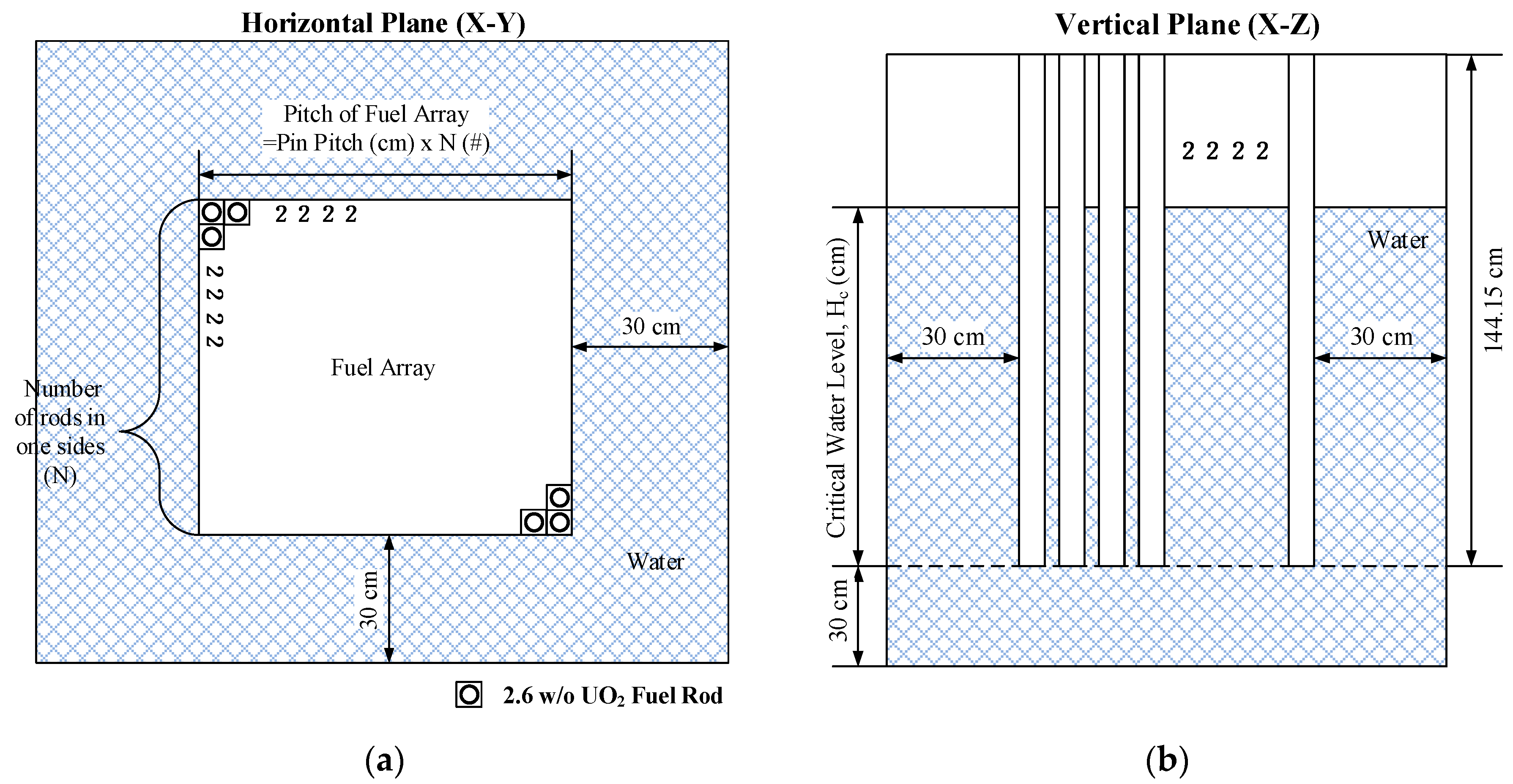
The TCA benchmarks [13,14] are critical experiment series for light-water moderated lattices using 17 × 17 2.6 w/o UO2 fuel rods arranged in a square array. The fuel rod array is surrounded by light-water in a 1.8 m core tank, whereas the pin-pitch and fuel pellet radii are 1.956 cm and 0.625 cm. Basically, the critical sizes were determined by adjusting the light water level. The TCA benchmark provides various measured parameters, such as the temperature coefficient, the extrapolation length, and the critical buckling. The experiments were performed using various configurations between 1963 and 1975. Based on these experiments, eighteen configurations were provided in the International Criticality Safety Benchmark Problem (ICSBEP) [13]. Among them, five experimental cases (i.e., case 4–case 8) were selected for this study. Table 2 shows the specifications of the five selected benchmark problems. Figure 2a,b display the horizontal and vertical cross sections for the TCA benchmark problems. The 1.8 m water core tank of the critical facility was simplified as a 30-cm-thick side water reflector in the benchmark model. For each problem, the critical water level (Hc), measured horizontal extrapolation distance ( λ h ), and vertical extrapolation distance ( λ z ) are obtained from the experimental results. Using the measured extrapolation distances, the total critical buckling can be calculated as
B c 2 = B c , x 2 + B c , y 2 + B c , z 2 = ( π P A + λ h ) 2 + ( π P A + λ h ) 2 + ( π H c + λ z ) 2 ,
where PA is the pitch of a fuel rod array.

4.2. Critical Buckling Generation for TCA Benchmark Problem

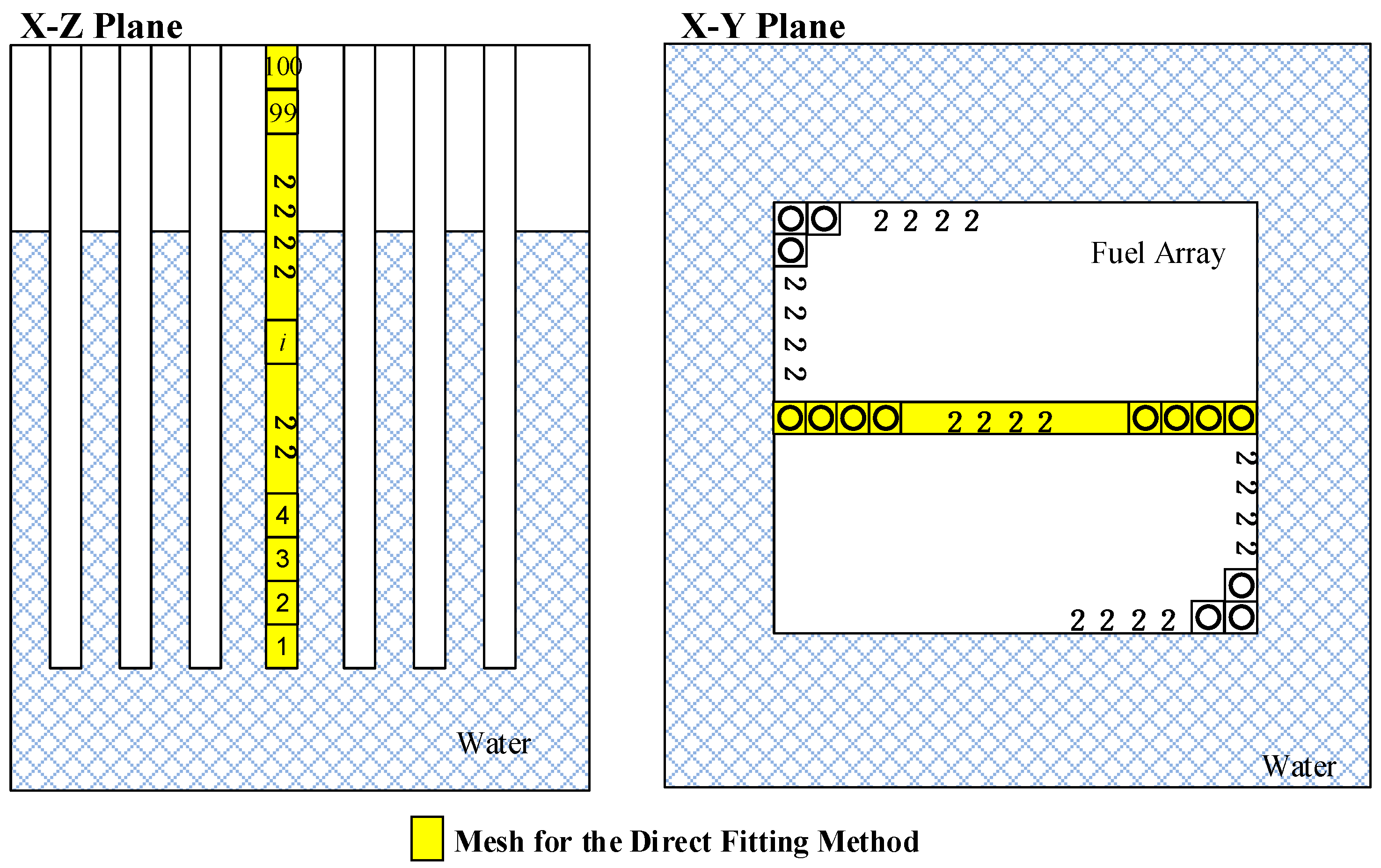
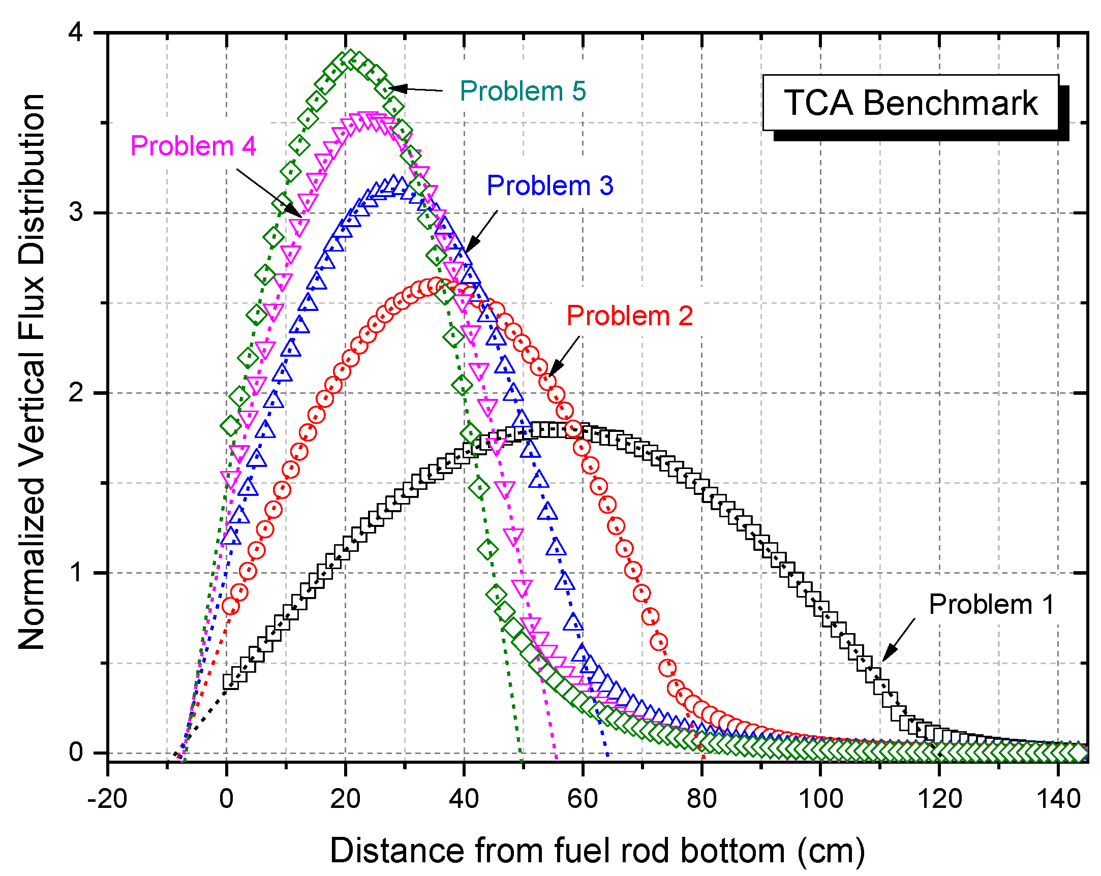
For each TCA benchmark problem, the critical buckling was generated using the McCARD [3] code, via both the B1 theory-augmented MC method and the direct fitting method. In the B1 method, the macroscopic cross sections for solving B1 multi-group equations were generated using MC calculations based on 50 inactive and 100 active cycles with 100,000 histories per cycle. The ACE-format continuous energy cross section libraries were processed based on the ENDF/B-VII.1 evaluated nuclear data library. The 47-group structure [1] was adopted for the B1 multi-group calculations. In the direct fitting method, the vertical extrapolation lengths were calculated using the MC calculations and the horizontal extrapolation lengths were taken from [13]. For the calculation of vertical extrapolation length, a single fuel rod located at the center of a fuel array was axially divided into one hundred meshes, as shown in Figure 3. Figure 4 shows the normalized vertical flux distributions and their fitted cosine functions for each problem. Table 3 shows the vertical extrapolation lengths determined using the direct fitting method. For all problems, the R2 values for their extrapolation lengths were more than 0.999. The maximum difference in the vertical extrapolation length between the experiment and the calculation was around 5.0% for problem 5.
Table 4 shows the critical buckling of McCARD, calculated using the B1 method and the direct fitting method. The relative differences in critical buckling between the reference and McCARD range from 0.1% to 1.1%. The maximum relative difference in the critical buckling occurred for problem 1. In all problems, the B1 calculations were conducted under the equivalent geometric data because the B1 method uses an infinite medium bounded by surfaces with a reflective boundary condition. Accordingly, the critical buckling results determined by the B1 method were the same, as shown in Table 4.
To confirm the accuracy of the criticality prediction, DeCART2D lattice code calculations were performed using the critical buckling. For the DeCART2D calculation, a ray spacing of 0.02 cm and two polar angles of 90° were used as the ray tracing option. All the DeCART2D calculations were conducted with the ENDF/B-VII.1 based 47-group cross section library [17]. Table 5 shows the effective multiplication factors (keff) of DeCART2D for the five TCA benchmark problems. The maximum differences in keff for the reference is about 143 pcm whereas that for the B1 method is about 187 pcm. The direct fitting method gives a maximum error of 217 pcm. It is well known that the general design review criterion (DRC) of critical boron concentration (CBC) in a typical PWR start-up and operation is 500 pcm. Therefore, it can be confirmed that all DeCART2D results agree with the experiments within the DRC of CBC.

4.3. Uncertainty Analysis of Critical Buckling Based on Cross Section Uncertainties

The SNU S/U formulations to quantify the uncertainties arising from the statistical uncertainty and the uncertain input data, which were derived in Section 3.1, were incorporated into the B1 method-based critical buckling generation module of the McCARD code. The module was then used to estimate the uncertainties of the critical buckling for the TCA benchmark problems. The nuclear cross-section data, including the covariance data files for computing both the critical buckling and their uncertainties, were obtained from the ENDF/B-VII.1 and ENDF/B-VIII.0 evaluated nuclear data libraries. The covariance data files of only the two major uranium isotopes (i.e., 235U and 238U) and 16O were considered. Table 6 presents the percentile relative error (%RE), which is defined as 100 × σ ( B c 2 ) / B c 2 , for each critical buckling. All relative errors of critical buckling caused only by statistical uncertainties were less than 0.11% whereas those from both statistical and microscopic cross section uncertainties for ENDF/B-VII.1 and ENDF/B-VIII.0 were less than 3.18% and 1.49%, respectively. It is clear that the most significant contributor of both evaluated nuclear data file libraries to σ ( B c 2 ) is the uncertainties of the 238U capture cross section (MT = 102).
Figure 5 compares the microscopic cross section uncertainties between the ENDF/B-VIII.0 and ENDF/B-VII.1 evaluated nuclear data libraries. As mentioned in [18], the change in the uncertainties in the critical buckling comes from the difference in the evaluations by each covariance provider. As shown in Figure 5, the uncertainties of the 235U capture cross section, the 238U capture cross section, and the number of neutrons (v) per 235U fission (MT = 452) in ENDF/B-VIII.0 are smaller than those in ENDF/B-VII.1 in almost the entire energy region. By contrast, the uncertainties of the 235U fission cross section (MT = 18) in ENDF/B-VIII.0 are larger than those in ENDF/B-VII.1 in the thermal and fast energy regions. Consequently, the decreases (or increases) in each cross section’s uncertainty lead to decreases (or increases) in the critical buckling uncertainty.

4.4. Uncertainty Analysis of Critical Buckling Based on Input Design Data

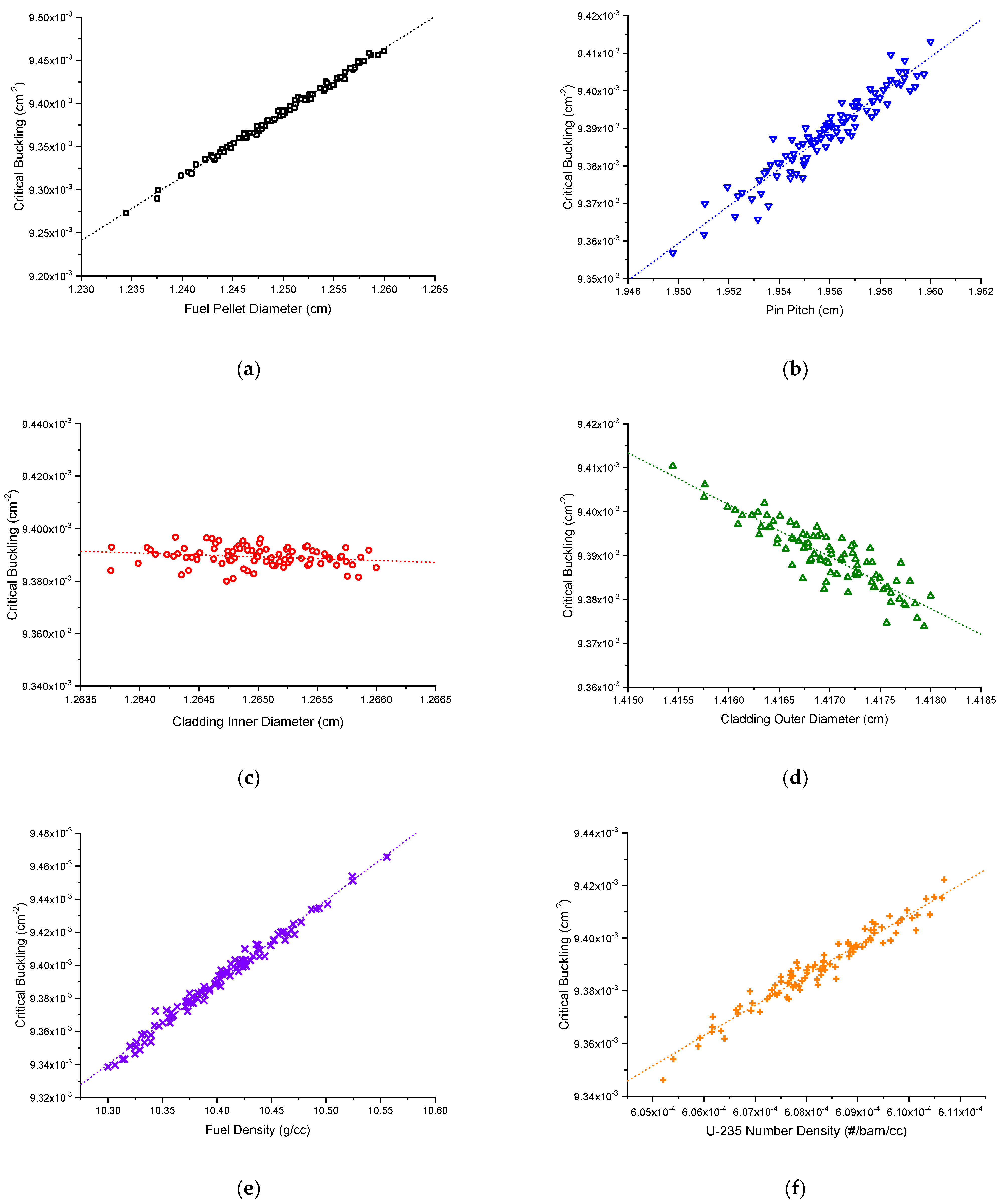
The S.S. method can be easily utilized to quantify uncertainties of nuclear design parameters, including critical buckling, through calculations of the inputs, which are sampled from the standard deviation or tolerance of the input parameters. The TCA experiment benchmark provides the uncertainty of input design data such as the uranium composition, the diameter of the UO2 pellet, the inner and outer diameter of the aluminum alloy cladding, the pin pitch, and the density of the UO2 pellet. In this section, the critical buckling uncertainty based on these uncertainties was estimated using the S.S. method. All S.S. calculations were performed using McCARD and MIG (McCARD Input Generator) code [9]. For each case, the 100 McCARD calculations were conducted using the ENDF/B-VII.1 cross section library. Table 7 presents the uncertainties of the critical buckling from geometric and material data uncertainties for Problem 1. The percentile relative errors (%RE) of the critical buckling by the UO2 pellet diameter uncertainty, the aluminum cladding inner and outer diameter uncertainty, and the pin pitch uncertainty are 0.41%, 0.04%, 0.07%, and 0.12%, respectively. The uncertainties of the critical buckling by the 235U enrichment uncertainty and the UO2 pellet density uncertainty are respectively 0.15% and 0.28%. Figure 6 displays the distributions of critical buckling from each input design data sampling. It was observed that the critical buckling increases as the fuel pellet diameter, pin pitch, fuel pellet number density, or 235U enrichment increases, whereas it slightly decreases as the cladding inner or outer diameter increases. These linear relationships for each case depend on the change in the reactivity. The increase in the fuel pellet diameter leads to an increase in the reactivity, the leakage term for the critical state, and the critical buckling, in sequence.

5. Conclusions

In this study, the B1 theory-augmented Monte Carlo (MC) method was adopted for the generation of critical buckling. To examine the critical buckling using the B1 theory-augmented MC method, five TCA critical experiment benchmark cases were considered. For each case, the effective multiplication factor of DeCART2D, which was calculated with the critical buckling determined by the B1 method, agreed with the experimental value within the well-known general criteria of CBC in a typical PWR start-up and operation. Therefore, it can be concluded that the B1 theory-augmented MC method can provide accurate and reliable critical buckling for a practical system.
Moreover, a new formulation to estimate the uncertainties of the critical buckling as determined by the B1 theory-augmented MC method was derived from the so-called ‘SNU S/U formulation’, and this can be used to link input uncertainties to output uncertainties. The SNU S/U formulation was able to explain the uncertainty propagation in the critical buckling generation. It was then utilized to compute the uncertainties of the critical buckling for a TCA critical experiment under the assumption that nuclear cross-section data have uncertainties. This application of the ‘SNU S/U formulation’ also shows that this formulation can serve as an effective and useful tool to examine the influence of nuclear data uncertainty on nuclear core design and safety. Moreover, it can be utilized to identify the significant contributors to the uncertainties of the other nuclear core design parameters.
The procedure involving the new formulation will be particularly useful as a practical way to provide the uncertainties of the critical buckling required for V&V of the DeCART2D code.

Author Contributions

Conceptualization, H.J.P.; methodology, H.J.P. and J.Y.C.; software, H.J.P.; validation, H.J.P.; formal analysis, H.J.P.; investigation, H.J.P.; resources, H.J.P.; data curation, H.J.P.; writing—original draft preparation, H.J.P.; writing—review and editing, H.J.P. and J.Y.C.; visualization, H.J.P.; supervision, H.J.P.; project administration, J.Y.C.; funding acquisition, J.Y.C. All authors have read and agreed to the published version of the manuscript.

Funding

This research was supported by “Support of McCARD Monte Carlo Code Application for Nuclear Reactor Shielding Design Analysis” Project.

Institutional Review Board Statement

Not applicable.

Informed Consent Statement

Not applicable.

Data Availability Statement

Not applicable.

Conflicts of Interest

The authors declare no conflict of interest. The funders had no role in the design of the study; in the collection, analyses, or interpretation of data; in the writing of the manuscript, or in the decision to publish the results.

Abbreviations

MOCMethod of Characteristics
KAERIKorea Atomic Energy Research Institute
MCMonte Carlo
FGCsFew Group Constants
S/USensitivity and Uncertainty
S.S.Stochastic Sampling
SNUSeoul National University
IMSInfinite Medium Spectrum
CSCritical Spectrum
ICSBEPInternational Criticality Safety Benchmark Problem
DRCDesign Review Criterion
CBCCritical Boron Concentration
%REPercentile Relative Errors

References

  1. Cho, J.Y.; Shim, C.; Han, T.Y.; Lee, K.; Lee, C.; Song, J.S.; Park, S.Y.; Park, H.J.; Jeong, H.J.; Jo, C.K.; et al. DeCART2D v1.1 User’s Manual; KAERI/UM-40/2016; Korea Atomic Energy Research Institute: Daejeon, Korea, 2016. [Google Scholar]
  2. Cho, J.Y.; Jeong, H.J.; Song, J.S.; Park, S.Y.; Lee, K.; Lee, C.; Shim, C.; Park, H.J.; Choi, Y.; Koo, B.S. MASTER v4.0 User’s Manual; KAERI/UM-41/2016; Korea Atomic Energy Research Institute: Daejeon, Korea, 2016. [Google Scholar]
  3. Shim, H.J.; Han, B.S.; Jung, J.S.; Park, H.J.; Kim, C.H. McCARD: An Monte Carlo Code for Advanced Reactor Design and Analysis. Nucl. Eng. Tech. 2012, 44, 161–176. [Google Scholar] [CrossRef] [Green Version]
  4. Boyd, W.; Nelson, A.; Romano, P.K.; Shaner, S.; Forget, B.; Smith, K. Multigroup Cross-Section Generation with the OpenMC Monte Carlo Particle Transport Code. Nucl. Techonol. 2019, 205, 928–944. [Google Scholar] [CrossRef]
  5. Lee, H.; Kim, W.; Zhang, P.; Lemaire, M.; Khassenov, A.; Yu, J.; Jo, Y.; Park, J.; Lee, D. MCS—A Monte Carlo Particle Transport Code for Large-Scale Power Reactor Analysis. Ann. Nucl. Energy 2020, 139, 107276. [Google Scholar] [CrossRef]
  6. Yamamoto, T. Monte Carlo method with complex weights for neutron leakage-corrected calculations and anisotropic diffusion coefficient. Ann. Nucl. Energy 2012, 50, 141–149. [Google Scholar] [CrossRef]
  7. Yamamoto, T.; Sakamoto, H. Monte Carlo method for solving a B1 equation with complex-valued buckling in asymmetric geometries and generation of directional diffusion coefficients. Ann. Nucl. Energy 2018, 122, 37–46. [Google Scholar] [CrossRef]
  8. Shim, H.J.; Cho, J.Y.; Song, J.S.; Kim, C.H. Generation of Few Group Diffusion Theory Constants by Monte Carlo Code. Trans. Am. Nucl. Soc. 2008, 343, 343–345. [Google Scholar]
  9. Park, H.J.; Shim, H.J.; Kim, C.H. Generation of Few-Group Diffusion Theory Constants by Monte Carlo Code McCARD. Nucl. Sci. Eng. 2012, 172, 66–77. [Google Scholar] [CrossRef]
  10. Park, H.J.; Shim, H.J.; Joo, H.G.; Kim, C.H. Uncertainty Quantification of Few-group Diffusion Theory Constants Generated by the B1 Theory-Augmented Monte Carlo Method. Nucl. Sci. Eng. 2013, 175, 28–43. [Google Scholar] [CrossRef]
  11. Fridman, E.; Leppanen, J. On the use of the Serpent Monte Carlo code for few group cross section generation. Ann. Nucl. Energy 2011, 38, 1399–1405. [Google Scholar] [CrossRef]
  12. Park, H.J.; Shim, H.J.; Kim, C.H. Uncertainty Propagation in Monte Carlo Depletion Analysis. Nucl. Sci. Eng. 2011, 167, 196–208. [Google Scholar] [CrossRef]
  13. Miyoshi, Y.; Arakawa, T. Critical Arrays of Low-Enriched UO2 Fuel Rods with Water-to-Fuel Volume Ratio Ranging from 1.5 to 3.0; NEA/NSC/DOC(95)03; OECD Nuclear Energy: Paris, France, 2006; Volume IV. [Google Scholar]
  14. Suzaki, T. Subcriticality Determination of Low-Enriched UO2 Lattices in Water by Exponential Experiment. J. Nucl. Sci. Technol. 1991, 28, 1067–1077. [Google Scholar] [CrossRef]
  15. Knief, R.A. Nuclear Engineering Theory and Technology of Commercial Nuclear Power, 2nd ed.; American Nuclear Society: La grange Park, IL, USA, 2008; pp. 114–119. [Google Scholar]
  16. Macfarlane, R.; Muir, D.W.; Boicourt, R.M.; Kahler, A.C., III; Conlin, J.L. The NJOY Nuclear Data Processing System Version; LA-UR-17-20093; Los Alamos National Laboratory: Los Alamos, NW, USA, 2016.
  17. Park, H.J.; Kim, K.S.; Hong, S.G.; Song, J.S. An improved DeCART Library Generation Procedure with Explicit Resonance Interference using Continuous Energy Monte Carlo Calculation. Ann. Nucl. Energy. 2017, 105, 95–105. [Google Scholar] [CrossRef]
  18. Park, H.J.; Kang, H.; Lee, H.C.; Cho, J.Y. Comparison of ENDF/B-VIII.0 and ENDF/B-VII.1 in criticality, depletion benchmark, and uncertainty analyses by McCARD. Ann. Nucl. Energy. 2019, 131, 443–459. [Google Scholar] [CrossRef]
Figure 1. Flowchart of critical buckling generation using the B1 theory-augmented MC method.
Energies 14 02578 g001
Figure 2. (a) Horizontal cross section of a lattice core in the TCA Benchmark Problems; (b) vertical cross section of a lattice core in the TCA Benchmark Problems.
Energies 14 02578 g002
Figure 3. Meshes for vertical extrapolation length calculation.
Energies 14 02578 g003
Figure 4. Normalized vertical flux and its fitted function for the direct fitting method.
Energies 14 02578 g004
Figure 5. Comparison of the microscopic cross section uncertainties between ENDF/B-VIII.0 and ENDF/B-VII.1.
Energies 14 02578 g005
Figure 6. Distribution of critical buckling by (a) sampled fuel pellet diameters; (b) sampled pin pitches; (c) sampled cladding inner diameters; (d) sampled cladding outer diameters; (e) sampled fuel mass densities; (f) sampled 235U number densities.
Energies 14 02578 g006
Table 1. Functional relation between input and output variables for each step in critical buckling generation using the B1 theory-augmented MC method.
StepInput (I)
Variables
Output(O)
Variables
Functional Relation
Between the I/O Variables
I σ α , g , i ,   N i m φ g φ g = φ g ( σ α , g , i ,   N i m )
r α , g , j m r α , g , j m = r α , g , j m ( σ α , g , i ,   N i m )
II N j m , r α , g , j m , φ g Σ α , g Σ α , g = Σ α , g ( N j m , r α , g , j m , φ g )
III Σ α , g B c B c = B c ( , Σ α , g , )
Table 2. Specifications of the selected TCA experiment benchmark problems.
Problem No.Case No. 1Number of Rods in One Side (N)Critical Height Level (cm)Extrapolation Length (cm)Total Buckling (×10−3 cm−2)
Vertical   ( λ z ) Horizontal   ( λ h )
1Case 417114.59 ± 1.6912.2 ± 0.313.9 ± 0.89.49 ± 0.21
2Case 51875.32 ± 0.9012.2 ± 0.313.9 ± 0.89.47 ± 0.19
3Case 61960.38 ± 0.2112.2 ± 0.313.9 ± 0.89.44 ± 0.17
4Case 72051.65 ± 0.1712.2 ± 0.313.9 ± 0.89.44 ± 0.15
5Case 82146.01 ± 0.0812.2 ± 0.313.9 ± 0.89.44 ± 0.14
1 These are the sub-case numbers of the LCT-006 problem in the ICSBEP benchmark.
Table 3. Vertical extrapolation lengths of TCA experiment benchmark problems.
Problem
No.
Vertical Extrapolation Length ( λ z )
by Direct Fitting Method (×10−3 cm−2)
ExpMcCARDR2
112.2 ± 0.312.50.9998
212.2 ± 0.311.70.9996
312.2 ± 0.312.60.9993
412.2 ± 0.312.00.9999
512.2 ± 0.312.80.9998
Table 4. Vertical extrapolation lengths of TCA experiment benchmark problems.
Problem
No.
Critical Buckling (×10−3 cm−2)
ExpB1 MethodDirect Fitting Method
ValueC/E 1ValueC/E 1
19.492 ± 0.219.3880.9899.4900.999
29.474 ± 0.199.3910.9919.4881.002
39.444 ± 0.179.3890.9949.4240.998
49.443 ± 0.159.3900.9949.4581.002
59.444 ± 0.149.3880.9949.3790.993
1 C/E = (calculated critical buckling)/(experimental critical buckling).
Table 5. keff of DeCART2D with critical buckling from vertical extrapolation length.
Problem
No.
keff of DeCART2D with Critical Buckling
ExperimentsB1 MethodDirect Fitting Method
keffDiff 1keffDiff 1keffDiff 1
10.99857−1431.001851850.99863−137
20.99915−851.001781780.99868−132
31.00010101.001841841.0007171
41.00012121.001801800.99963−37
51.00011111.001871871.00217217
1 Diff (pcm) = (keff − 1)/(keff) × 105.
Table 6. Uncertainties of critical buckling based on cross section uncertainties (Problem 1).
IsotopeReaction TypeCase Percentile   Relative   Errors   of   Critical   Buckling   ( σ ( B c 2 ) / B c 2 ,   % RE )   1
ENDF/B-VII.1ENDF/B-VIII.0
235U ν ν ( 235 U ) 1.22%0.82%
( n , f ) σ f ( 235 U ) 0.32%0.33%
( n , γ ) σ γ ( 235 U ) 1.01%0.44%
238U ν ν ( 235 U ) 0.11%0.11%
( n , f ) σ f ( 238 U ) 0.11%0.16%
( n , γ ) σ γ ( 238 U ) 1.76%1.04%
16O ( n , γ ) σ γ ( 238 U ) 0.11%0.11%
Total3.18%1.49%
1 All uncertainties include the statistical uncertainty (=0.11%).
Table 7. Uncertainties of critical buckling based on geometric and material data uncertainties.
ItemValue Percentile   Relative   Errors   of   Critical   Buckling   ( σ ( B c 2 ) / B c 2 ,   % RE )
235U composition (wt.%)2.596 ± 0.0050.15%
UO2 pellet density (g/cm3)10.4 ± 0.050.28%
UO2 pellet diameter (cm)1.25 ± 0.0050.41%
Al alloy cladding inner diameter (cm)1.265 ± 0.00050.04%
Al alloy cladding thickness (cm)0.0076 ± 0.00050.07%
Lattice pitch (cm)1.956 ± 0.0020.12%
Publisher’s Note: MDPI stays neutral with regard to jurisdictional claims in published maps and institutional affiliations.