Article

Torque Ripple Reduction Method in a Multiphase PM Machine for No-Fault and Open-Circuit Fault-Tolerant Conditions

School of Engineering, University of Leicester, Leicester LE1 7RH, UK
*
Author to whom correspondence should be addressed.
Energies 2021, 14(9), 2615; https://doi.org/10.3390/en14092615
Submission received: 6 March 2021 / Revised: 22 April 2021 / Accepted: 29 April 2021 / Published: 2 May 2021

Abstract

:
This paper presents a method that has been developed to reduce the torque ripples under healthy and open-circuit fault-tolerant (OCFT) conditions for a multiphase permanent magnet (PM) machine. For smooth torque, both the phase current and the back electromotive force (back-EMF) should be purely sinusoidal. To improve the torque in a multiphase machine, higher-order current harmonics are injected, which are related to the harmonics in the back-EMF. For this reason, generally, multiphase machines are designed with higher-order back-EMF harmonics. However, these harmonics produce ripples in the torque. In light of this, a torque ripple cancellation method has been developed that first determines an additional current component from the harmonic content of the back-EMF and then injects these additional components to cancel the torque ripple. It has been found that this new torque ripple cancellation method works for both faultless and faulty conditions in a five-phase PM machine. The method has been validated using Finite Element Analysis, and the results are presented in this paper.

Graphical Abstract

1. Introduction

A machine that has more than three phases is called a multiphase machine, as detailed in the literature [1,2,3]. Multiphase machines first came about because of the limited current ratings of power electronic devices in an inverter circuit. In recent years, multiphase machines have drawn increasing interest by researchers, due to their advantages [4,5,6,7,8,9,10,11,12,13,14]. Compared to the traditional three-phase counterpart, multiphase machines have many advantages. The three most important advantages can be given as: (1) Multiphase machines enable us to use lower rating semiconductor switches, due to power-sharing over more than three phases [1,3,15], (2) Multiphase machines can be controlled by using only two degrees of freedom, i.e., flux and torque producing current components. The remaining degrees of freedom can be used for other purposes, such as controlling two or more series-connected sinusoidal machines independently, using a single inverter [16,17,18,19,20,21,22]. (3) Multiphase machines have better fault-tolerant capability than their three-phase counterparts [23,24,25,26,27,28,29].
Torque ripple is one of the most important problems in electrical machines regardless of the machine type. Many applications require a smooth (ripple-free) torque, such as elevator systems. There are many factors causing torque ripple in a PM machine: (1) The rotor magnetic field interacts with the stator slot even if there is no current flowing in the stator winding. Because of this interaction, an unwanted periodic torque pulsation, called cogging torque, arises [30,31,32]. (2) The second reason for torque pulsation is the interaction between the rotor magnetic field and phase current harmonics [30,31,33]. Producing a purely sinusoidal rotor magnet flux linkage is very difficult because of magnetic saturation and the tolerances in the manufacturing process [32,33]. (3) The third reason for torque ripple is due to unwanted stator current harmonics produced by the dead zone time of the inverter circuit [34,35,36]. As a result, the stator current will contain the higher-order current harmonics. These current harmonics will interact with the PM flux linkage even if it is purely sinusoidal, which will produce unwanted torque pulsations [35].
Many studies have been undertaken by researchers to suppress torque ripple. There are two methods to reduce torque ripple in a machine. The first one is to improve the design of the machine, and the second focuses on the control of the machine. From the machine design aspect, e.g., shaping rotor magnets and stator slot surface [12,37,38], skewing the rotor magnets or stator windings [30], choosing the proper number of slots and winding distribution [39], arranging PM pole arc [38], and applying the other machine design techniques to reduce the ripple torque without changing the average torque will nearly eliminate the cogging torque. In the control side of the machine, generally, researchers can suppress the torque ripple by injecting the higher-order stator current harmonics [32,33,36,40,41]. Injected current harmonics can be determined by using optimization techniques, such as the Lagrange multipliers method, or an artificial neural network, and so on. All of these methods are used to determine the coefficients of the injected current harmonics, and generally, these studies concentrate on the healthy condition of three-phase machines. Some methods can also work under faulty conditions [42,43].
These methods mentioned above can also be applied to multiphase machines. Besides the torque ripple under the healthy condition, the multiphase machine produces torque ripple under faulty conditions as well, but with a much higher amplitude compared to the healthy condition. This paper focuses on reducing the torque ripple of PM multiphase machines under healthy and phase OCFT conditions. There are several methods to run the machine under an OCFT condition [23,25,27,29]. In [23], Parsa et al. developed an OCFT condition for a sinusoidally distributed winding or purely sinusoidal back-EMF PM machines. However, this method will produce a torque ripple in a nonsinusoidal back-EMF machine because of the unwanted interactions between the higher-order harmonics of the back-EMF and phase current. In [29], a method was developed by keeping the phase currents the same and equal to each other under OCFT control. This is a unique fault-tolerant control method—nevertheless, it is for sinusoidal back-EMF PM or sinusoidally distributed winding machines. Therefore, there will be ripples due to back-EMF and phase current harmonic interaction for a nonsinusoidal machine. Dwari et al. developed an OCFT control technique for trapezoidal back-EMF PM machines [25]. This method produces a smooth torque under OCFT conditions, since the amplitude of the phase currents and their relative phase angles are arranged to eliminate the pulsating terms of the instantaneous power (I-power). This method can also be applied under the healthy condition by considering the higher-order back-EMF harmonics. Mohammadpour et al. proposed a fault-tolerant control method under OCFT and short-circuit fault-tolerant conditions for multiphase machines by using the Lagrange equations [27]. This method can be applied to both sinusoidal and nonsinusoidal back-EMF machines, and it produces ripple-free torque under fault conditions. This method can also be applied to the healthy condition of the machine.
In this paper, a method is presented that was developed to suppress torque pulsations, due to the interaction between the back-EMF harmonics and the phase current harmonics for healthy and OCFT conditions. The other sources of torque ripple are ignored. Torque pulsations, due to harmonic interaction, are discussed in detail for both healthy and OCFT conditions by the authors of [44]. In the healthy condition, the I-power component, due to the interaction of the fundamental component of the back-EMFs and phase currents, is smooth. However, the higher-order harmonics are present in the back-EMF of a nonsinusoidal back-EMF machine. The interaction between the fundamental current components and the higher-order back-EMF harmonics, such as the 9th and 11th harmonics, causes ripple under healthy conditions. If the third harmonic of the stator current is injected for torque improvement, there will be another torque pulsation, due to interaction between the third harmonic current component, and the 7th and 13th harmonics of the back-EMF. The amplitude of the pulsations depends on the amplitude of these back-EMF harmonics. Both of these pulsations have the same pulsating frequency, and it is ten times the frequency of the fundamental phase current. Under the OCFT condition for a multiphase machine, only the interaction between the fundamental components of the back-EMF and phase current, or the interaction between the third harmonic components of the back-EMF and phase current produces smooth I-power. The other harmonic interactions between the back-EMF and phase current cause ripple in the I-power and in the torque. Because of this, torque ripple under OCFT conditions is higher than those under healthy conditions.
The various sources of torque ripple have been described above. If a solution can be developed to suppress these unwanted harmonic interactions, then torque ripple can be suppressed. At this point, an additional current component injection method is proposed to make zero these I-power components that produce ripple. Derivation of the required additional current component is explained in detail in Section 3. The organization of the paper is as follows. In Section 2, the I-power approach is described. The proposed method to reduce the torque ripple is introduced in Section 3. Analytical analysis has been made in Section 4 and Section 5 for the healthy and faulty conditions. In Section 6, the proposed method has been validated in an FEA software model. Finally, Section 7 concludes the paper.

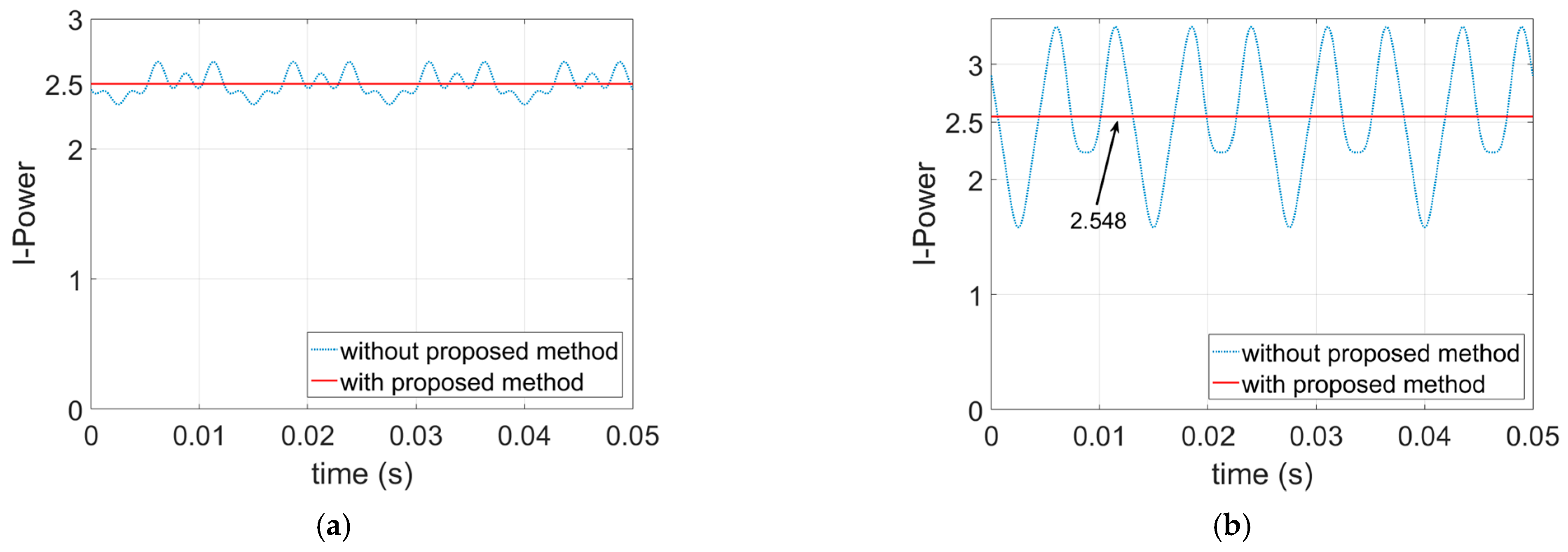
2. Instantaneous Power Approach

The torque produced by a five-phase PM machine is given in (1) below, where ω r is the rotor angular speed and θ is the electrical angle.
T = 1 ω r [ i a ( θ ) e a ( θ ) + i b ( θ ) e b ( θ ) + i c ( θ ) e c ( θ ) + i d ( θ ) e d ( θ ) + i e ( θ ) e e ( θ ) ]
The combined fundamental plus third harmonic currents can be given as in (2).
i a ( θ ) = i a 1 ( θ ) + i a 3 ( 3 θ ) + i b ( θ ) = i b 1 ( θ ) + i b 3 ( 3 θ ) + i c ( θ ) = i c 1 ( θ ) + i c 3 ( 3 θ ) + i d ( θ ) = i d 1 ( θ ) + i d 3 ( 3 θ ) + i e ( θ ) = i e 1 ( θ ) + i e 3 ( 3 θ ) +
Multiphase machines can be supplied by using only the fundamental component or fundamental plus higher-order current harmonics. Generally, higher-order current harmonics are injected to improve the torque of the machine. For a five-phase machine, phase coils can be supplied with fundamental or fundamental plus third harmonic current components. The third harmonic stator current can be applied to a nonsinusoidal multiphase machine that includes the third harmonic in the back-EMF to improve the torque. The fundamental current components are given in (3), and the third harmonic of these currents can be written as in (4), where Im1 and Im3 are the amplitudes of the fundamental and third harmonic current components, respectively. The phasor diagram of the fundamental and third harmonic current components is illustrated in Figure 1.
i a 1 ( θ ) = I m 1 sin ( θ ) i b 1 ( θ ) = I m 1 sin ( θ 2 π 5 ) i c 1 ( θ ) = I m 1 sin ( θ 4 π 5 ) i d 1 ( θ ) = I m 1 sin ( θ 6 π 5 ) i e 1 ( θ ) = I m 1 sin ( θ 8 π 5 )
i a 3 ( θ ) = I m 3 sin ( 3 θ ) i b 3 ( θ ) = I m 3 sin ( 3 θ 6 π 5 ) i c 3 ( θ ) = I m 3 sin ( 3 θ 2 π 5 )     i d 3 ( θ ) = I m 3 sin ( 3 θ 8 π 5 )     i e 3 ( θ ) = I m 3 sin ( 3 θ 4 π 5 )    
The I-power of each phase can be expressed as a product of the phase current and back-EMF waveform of the related phase. The back-EMF waveform can be written as in (5) for a nonsinusoidal back-EMF machine, where E n represents the amplitude of the back-EMF harmonic, and k represents each of the five phases in a five-phase machine, i.e., k = 1 , 2 , 3 , 4 , 5 to represents phases a, b, c, d, and e, respectively.
e k ( θ ) = n = 1 , 3 , 5 , E n sin [ n ( θ ( k 1 ) 2 π 5 ) ]
For example, the back-EMF of phase A is as follow:
e a ( θ ) = E 1 sin ( θ ) + E 3 sin ( 3 θ ) + E 5 sin ( 5 θ ) +
According to the above definition, the I-power of the five-phase PM machine can be written as in (7). Back-EMF waveforms are obtained from the FEA model of the five-phase PM, as shown in Figure 2 and these back-EMF waveforms are taken as a reference to obtain the relative harmonic components of the back-EMFs, it is assumed that if E 1 = 1 pu, E 3 = 0.096 , E 5 = 0 , E 7 = 0.0332 , E 9 = 0.0301 , and E 11 = 0.0052 and if I m 1 = 1 pu then I m 3 = 0.2 I m 1 to ease the calculations.
P = [ i a ( θ ) e a ( θ ) + i b ( θ ) e b ( θ ) + i c ( θ ) e c ( θ ) + i d ( θ ) e d ( θ ) + i e ( θ ) e e ( θ ) ]

3. Methodology of Proposed Torque Ripple Reduction Method

In this section, a method is introduced to reduce the torque ripple by using the I-power approach in a PM multiphase machine. The I-power, due to the fundamental current component, can be written for a nonsinusoidal back-EMF five-phase PM machine as follow:
P 1 = i a 1 ( θ ) e a ( θ ) + i b 1 ( θ ) e b ( θ ) + i c 1 ( θ ) e c ( θ ) + i d 1 ( θ ) e d ( θ ) + i e 1 ( θ ) e d ( θ )
The resultant I-power, due to the fundamental current is given in (9).
P 1 = 5 2 I m 1 E 1 + I m 1 [ E 11 11 E 9 9 ] cos ( 10 θ ) +
The first term of Equation (9) produces smooth torque. However, the second term causes pulsations in the torque, since it is a cosine function, and its frequency is ten times the fundamental frequency of the phase current.
When the fundamental plus third harmonic current is applied to the coils of the multiphase PM machine, the resultant I-power can be written as in (10). The I-power ‘ P 1 ’ is already derived in (9).
P = P 1 + P 3
The I-power, due to the third harmonic current, can be given in (11).
P 3 = i a 3 ( θ ) e a ( θ ) + i b 3 ( θ ) e b ( θ ) + i c 3 ( θ ) e c ( θ ) + i d 3 ( θ ) e d ( θ ) + i e 3 ( θ ) e d ( θ )
And the resultant I-power, due to the third harmonic, is given by:
P 3 = 5 2 I m 3 E 3 + I m 3 [ E 13 13 E 7 7 ] cos ( 10 θ ) +
The summation of the I-powers, due to fundamental and third harmonic currents, is the resultant I-power, given in (13).
P = 5 2 I m 1 E 1 + 5 2 I m 3 E 3 + I m 1 [ E 11 11 E 9 9 ] cos ( 10 θ ) + I m 3 [ E 13 13 E 7 7 ] cos ( 10 θ )
The first and second terms of (13) will produce smooth torque. However, the third and fourth parts of (13) will produce ripples in torque. Both of the pulsating terms have the same frequency, and it is ten times the fundamental frequency. These pulsation parts should be eliminated to produce a smooth torque. The I-power with the third harmonic current component of each phase can be expressed as below in (14), where k is to represent phases a, b, c, d, and e, respectively.
P k = [ i k 1 ( θ ) + i k 3 ( 3 θ ) ] e k ( θ )
The I-power of the fundamental and third harmonic current components for each phase can be expressed in (15) and (16), respectively.
P k 1 = i k 1 ( θ ) e k ( θ )
P k 3 = i k 3 ( 3 θ ) e k ( θ )
In Equation (15), the fundamental current component will produce smooth torque when it interacts with the fundamental component of the back-EMF. Interaction of the fundamental current with the other back-EMF components apart from the fundamental back-EMF component will cause ripples in the torque in (15). As in (15), there will be smooth torque production when the third harmonic current component interacts with the third harmonic back-EMF components in (16). Pulsations will be produced due to interactions with the other back-EMF harmonics apart from the third harmonic back-EMF component. An additional current term can be added to remove the pulsating parts as in (17).
P k = [ i k 1 ( θ ) + i k 3 ( 3 θ ) + i k + ] e k ( θ )
Then, Equation (17) can be extended as below in (18):
P k = i k 1 ( θ ) e k 1 ( θ ) + i k 3 ( 3 θ ) e k 3 ( 3 θ ) + i k 1 ( θ ) [ e k ( θ ) e k 1 ( θ ) ] + i k 3 ( 3 θ ) [ e k ( θ ) e k 3 ( 3 θ ) ] + i k + e k ( θ )
The above Equation (18) can be split into two parts: One of the parts contributes to the smooth I-power, and the other part causes pulsations. The terms that contribute to the smooth torque is as below:
P k _ s m o o t h = I k 1 ( θ ) e k 1 ( θ ) + I k 3 ( 3 θ ) e k 3 ( 3 θ )
And the terms that cause pulsations are as follows:
P k _ p u l s a t i n g = i k 1 ( θ ) [ e k ( θ ) e k 1 ( θ ) ] + i k 3 ( 3 θ ) [ e k ( θ ) e k 3 ( 3 θ ) ] + i k + e k ( θ )
The pulsating part of the I-power should be equated to zero to derive the additional current component for eliminating the pulsating parts:
0 = i k 1 ( θ ) [ e k ( θ ) e k 1 ( θ ) ] + i k 3 ( 3 θ ) [ e k ( θ ) e k 3 ( 3 θ ) ] + i k + e k ( θ )
Then the additional current for each phase can be expressed as below:
i k + = i k 1 ( θ ) [ e k ( θ ) e k 1 ( θ ) ] + i k 3 ( 3 θ ) [ e k ( θ ) e k 3 ( 3 θ ) ] e k ( θ )
Hence, the new phase currents can be written as below in (23).
i a ( θ ) = i a 1 ( θ ) + i a 3 ( 3 θ ) + i a + i b ( θ ) = i b 1 ( θ ) + i b 3 ( 3 θ ) + i b + i c ( θ ) = i c 1 ( θ ) + i c 3 ( 3 θ ) + i c + i d ( θ ) = i d 1 ( θ ) + i d 3 ( 3 θ ) + i d + i e ( θ ) = i e 1 ( θ ) + i e 3 ( 3 θ ) + i e +
In Equation (23), the new currents are not balanced. Therefore, a neutral connection and a divided power bus are required for this proposed method.

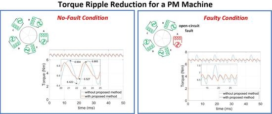
4. Torque Ripple Reduction Method for the No-Fault Condition

For the healthy (no-fault) condition, there are two ways to eliminate the torque ripples. The first one is to consider all the back-EMF harmonics as in (22) and calculating the additional current components according to this equation. The second approach is to take into account only the back-EMF harmonics that cause ripples in the torque. For example, the fundamental current components interact with the fundamental, 9th, and 11th harmonics of the back-EMF for the healthy condition. Interaction with the fundamental component of the back-EMF produces smooth torque. However, interaction with the 9th and 11th harmonics of the back-EMF causes ripples in the torque. Therefore, instead of considering all the back-EMF harmonics, considering only the 9th and 11th harmonics of the back-EMF will be enough for the fundamental current component to calculate the additional current component for the elimination of the torque ripples. So, the resultant I-power with the additional current components can be expressed as below in (24) for the healthy condition.
P k = I k 1 ( θ ) e k 1 ( θ ) + I k 3 ( 3 θ ) e k 3 ( 3 θ ) + I k 1 ( θ ) [ e k 9 ( 9 θ ) + e k 11 ( 11 θ ) ] + I k 3 ( 3 θ ) [ e k 7 ( 7 θ ) + e k 13 ( 13 θ ) ] + x k e k ( θ )
Then the alternative additional current for each phase can be expressed as in (25).
x k = I k 1 ( θ ) [ e k 9 ( 9 θ ) + e k 11 ( 11 θ ) ] + I k 3 ( 3 θ ) [ e k 7 ( 7 θ ) + e k 13 ( 13 θ ) ] e k ( θ )
By adding an additional current component in Equations (22) and (25) to each phase current in a PM five-phase machine, the resultant I-power for healthy conditions can be seen in Figure 3. I-power graphs are plotted when only the fundamental current components, and the fundamental plus third harmonic current components are applied to the windings. Without the proposed method, there are ripples in the I-power graphs. This means there will be ripples in the torque. With the proposed method, a smooth I-power has been obtained, so the overall torque will be smooth.

5. Torque Ripple Reduction for the Open-Circuit Fault-Tolerant Conditions

In this section, the proposed method has been applied to five OCFT conditions with and without third harmonic current components. In the healthy condition, there is no interaction between the fundamental current components and the third harmonic component of the back-EMF, and vice versa. However, for the OCFT conditions, the fundamental current component interacts with the third harmonic component of the back-EMF and vice versa. These interactions cause ripples in the torque. Therefore, it is better to use Equation (22) to calculate the additional current components for each phase to eliminate the torque ripples. The fault-tolerant method with third harmonic current components has been considered and developed by Yi Sui et al. [29], and the resulting torque under the healthy condition has been considered as a reference for the post fault conditions.

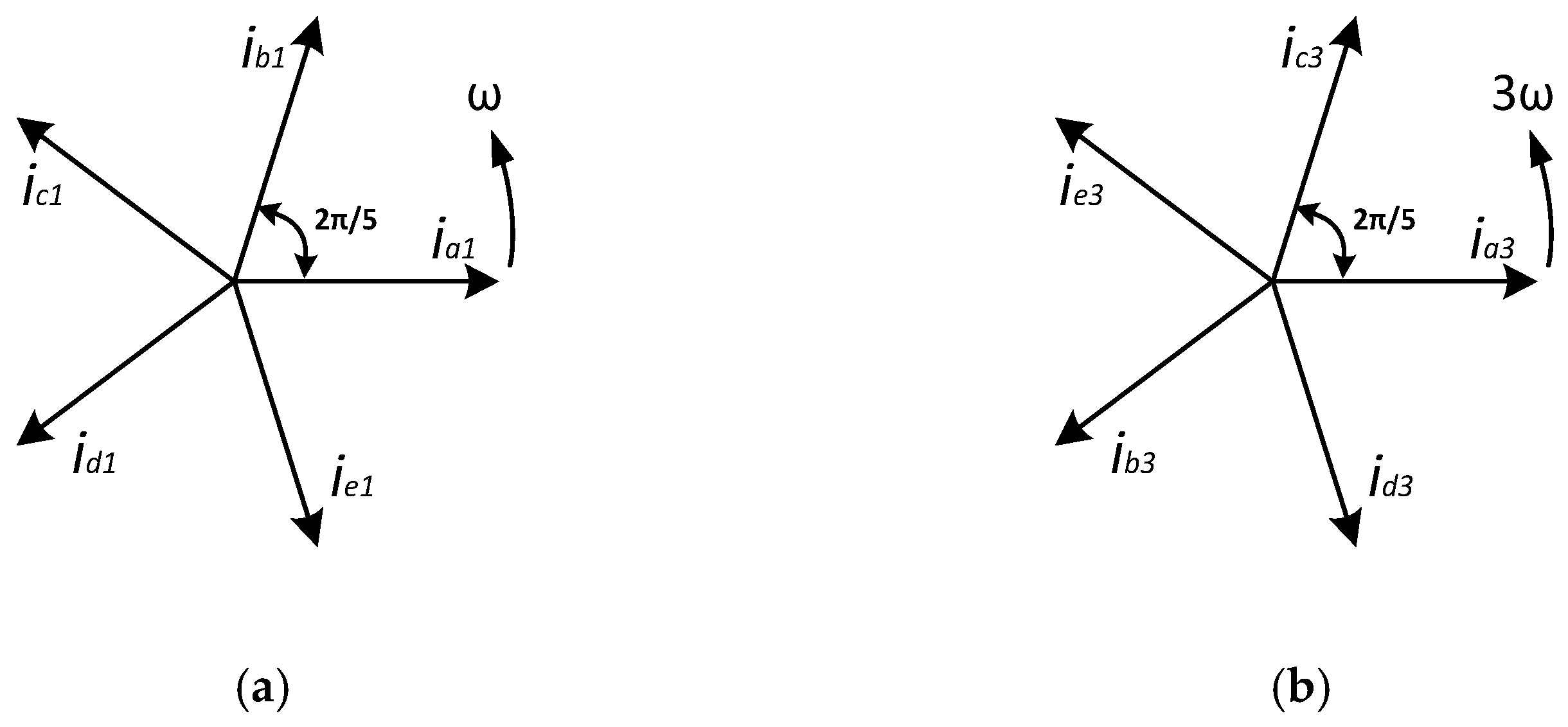
5.1. Single Phase Open-Circuit Fault-Tolerant Currents

It is assumed that Phase A is open-circuited. The fault-tolerant control currents with the third harmonic current component and the additional current are given in (26).
i b * ( θ ) = 1.314 [ I m 1 sin ( θ 3 π 10 ) + I m 3 sin ( 3 θ 11 π 10 ) ] + i b + i c * ( θ ) = 1.314 [ I m 1 sin ( θ 9 π 10 ) + I m 3 sin ( 3 θ 3 π 10 ) ] + i c + i d * ( θ ) = 1.314 [ I m 1 sin ( θ 11 π 10 ) + I m 3 sin ( 3 θ 17 π 10 ) ] + i d + i e * ( θ ) = 1.314 [ I m 1 sin ( θ 17 π 10 ) + I m 3 sin ( 3 θ 9 π 10 ) ] + i e +
I-power graphs have been plotted when only the fundamental, and fundamental plus third harmonic current components are applied. I-power graphs for the single-phase open-circuit (SPOC) conditions can be seen in Figure 4. Without the proposed method, there are ripples in the torque. However, it is clear from the graphs, ripples have been removed when the proposed method has been implemented.

5.2. Adjacent Double Phase Open-Circuit Fault-Tolerant Currents

It is assumed that Phase A and B are open-circuited for the adjacent double phase open-circuit (ADPOC) condition. Fault-Tolerant currents with the third harmonic and the additional current components are given in (27).
i c * ( θ ) = 1.77 I m 1 sin ( θ 14 π 15 ) + 2.14 I m 3 sin ( 3 θ 2 π 15 ) + i c + i d * ( θ ) = 1.77 I m 1 sin ( θ 6 π 5 ) + 2.14 I m 3 sin ( 3 θ 8 π 5 ) + i d + i e * ( θ ) = 1.77 I m 1 sin ( θ 22 π 15 ) + 2.14 I m 3 sin ( 3 θ 16 π 15 ) + i e +
I-power graphs with and without the proposed method for the ADPOC conditions can be seen in Figure 5.

5.3. Nonadjacent Double Phase Open-Circuit Fault-Tolerant Currents

It is assumed that Phase A and C are open-circuited for the nonadjacent double phase open-circuit (NADPOC) condition. Fault-Tolerant currents with the third harmonic and the additional current components are given in (28).
i b * ( θ ) = 2.14 I m 1 sin ( θ 2 π 5 ) + 1.77 I m 3 sin ( 3 θ 6 π 5 ) + i b + i d * ( θ ) = 2.14 I m 1 sin ( θ 14 π 15 ) + 1.77 I m 3 sin ( 3 θ 22 π 15 ) + i d + i e * ( θ ) = 2.14 I m 1 sin ( θ 28 π 15 ) + 1.77 I m 3 sin ( 3 θ 14 π 15 ) + i e +
I-power graphs with and without the proposed method for the NADPOC conditions are shown in Figure 6.

5.4. Adjacent Three-Phase Open-Circuit Fault-Tolerant Currents

Phase A, B, and E are assumed to be open-circuited for the adjacent three-phase open-circuit (ATPOC) fault-tolerant condition. Phase currents with the third harmonic component for the healthy phases are given in (29). I-power graphs with and without the proposed method for the ATPOC conditions are shown in Figure 7.
i c * ( θ ) = 2.63 I m 1 sin ( θ 7 π 10 ) + 4.25 I m 3 sin ( 3 θ π 10 ) + i c + i d * ( θ ) = 2.63 I m 1 sin ( θ 13 π 10 ) + 4.25 I m 3 sin ( 3 θ 19 π 10 ) + i d +

5.5. Nonadjacent Three-Phase Open-Circuit Fault-Tolerant Currents

Phase A, C, and D are assumed to be open-circuited for the nonadjacent three-phase open-circuit (NATPOC) fault-tolerant condition. Phase currents with the third harmonic component for the healthy phases are given in (30). I-power graphs with and without the proposed method for the NATPOC conditions are shown in Figure 8.
i b * ( θ ) = 4.25 I m 1 sin ( θ π 10 ) + 2.63 I m 3 sin ( 3 θ 13 π 10 ) + i b + i e * ( θ ) = 4.25 I m 1 sin ( θ 19 π 10 ) + 2.63 I m 3 sin ( 3 θ 7 π 10 ) + i e +

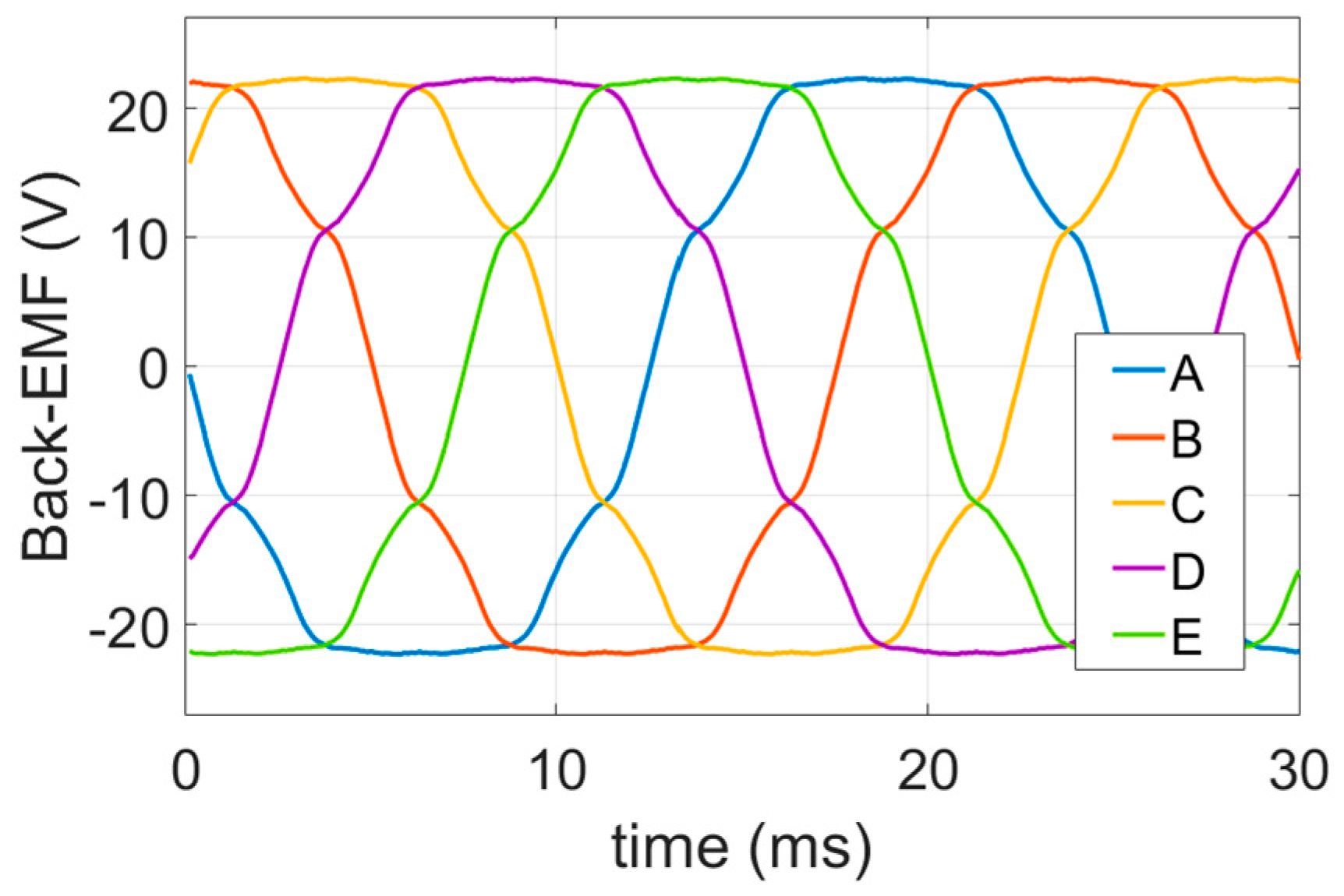
6. FEA Simulation Results of the Proposed Method

In this section of the paper, validation of the proposed method has been undertaken by using an FEA model of the five-phase fractional slot PM machine shown in Figure 9a. The machine is a double-layer fractional slot PM machine. The parameters of the five-phase PM machine model are given in Table 1. The back-EMF waveform of the machine is also shown in Figure 2, and the harmonic content includes: 100% fundamental, the 3rd harmonic: 9.6%, 5th: 0%, 7th: 3.32%, 9th: 3.01%, 11th: 0.52%. Cogging torque of the FEA model of the five-phase PM machine is shown in Figure 9b. The peak to the peak value of the cogging torque is 0.33 Nm.
Simulations have been done at 600 rpm rotor speed (or 10 rps), and at the electrical frequency of 40 Hz. 26 FEA simulations have been undertaken for both fundamental only, and fundamental plus third harmonic currents with and without the proposed method. Six of the simulations belong to the healthy condition, and the remaining simulations are for the five different OCFT conditions. The rated current of the five-phase PM multiphase machine has been used as a reference current for the simulations, so the fundamental current component I m 1 = 3.39 A and the third harmonic current component I m 3 = 0.2 x I m 1 .

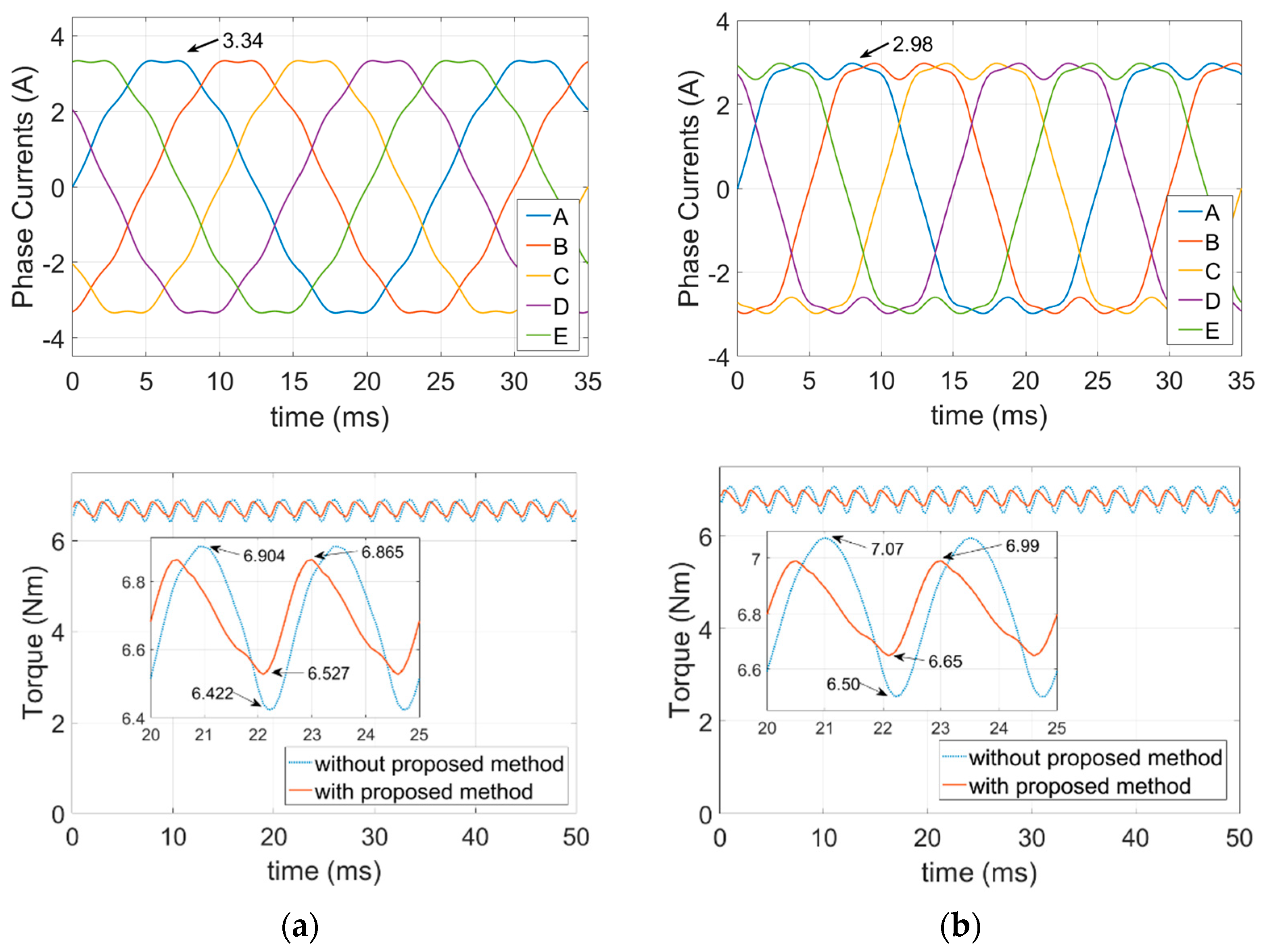
6.1. FEA Simulations of the Healthy Condition

Two different additional currents for each phase have been obtained in (22) and (25) for the healthy condition (Healthy1 and Healthy2, respectively). Simulations have been undertaken by using these additional currents. The new set of phase currents can be seen in Figure 10a,b by using Equation (22). Figure 10a is for the fundamental only currents, and Figure 10b shows the fundamental plus third harmonic currents with the proposed method. FEA torque results of these new sets of currents also can be seen in the same figures. Torque ripples caused by the higher-order harmonics of the back-EMF are all nearly eliminated by using the proposed method. The only torque ripples that remain are those from the cogging torque.
The new set of currents also obtained by using Equation (25) for the healthy condition. The new set of currents and the torque results are shown in Figure 11a,b. Figure 11a is for the fundamental only currents, and Figure 11b belongs to the fundamental plus third harmonic currents. Torque ripples caused by the higher-order harmonics in the back-EMF are nearly eliminated for both conditions.

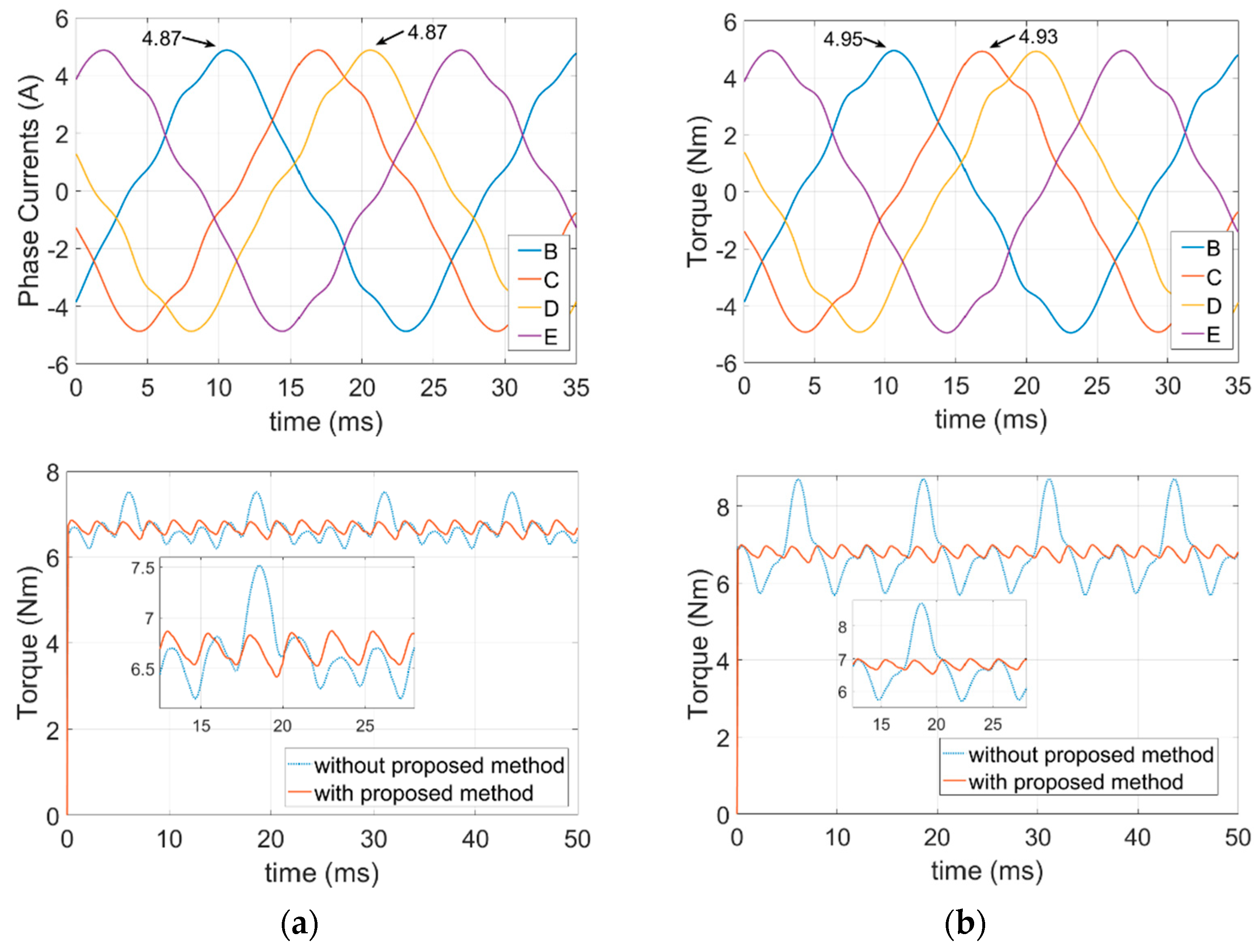
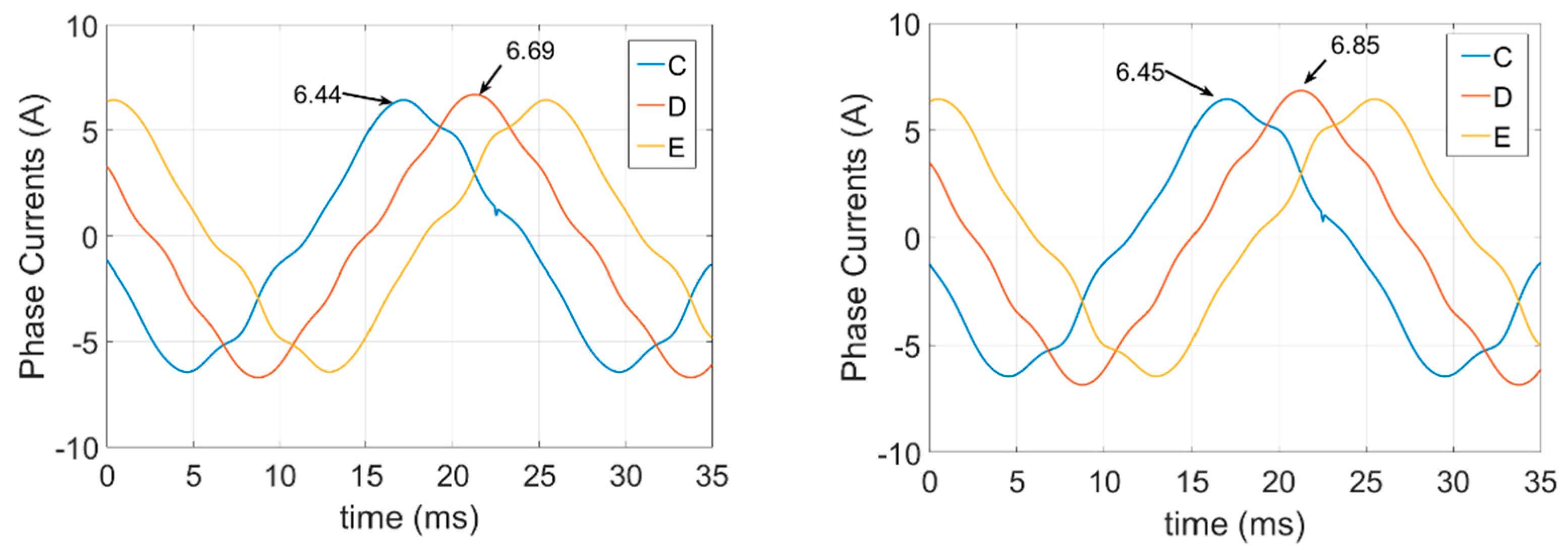
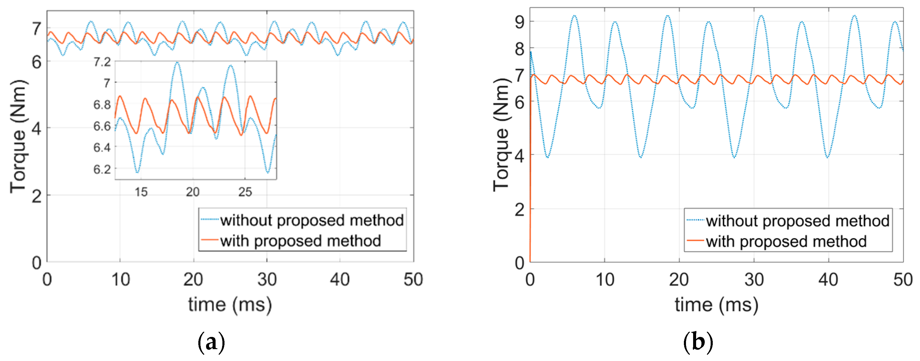
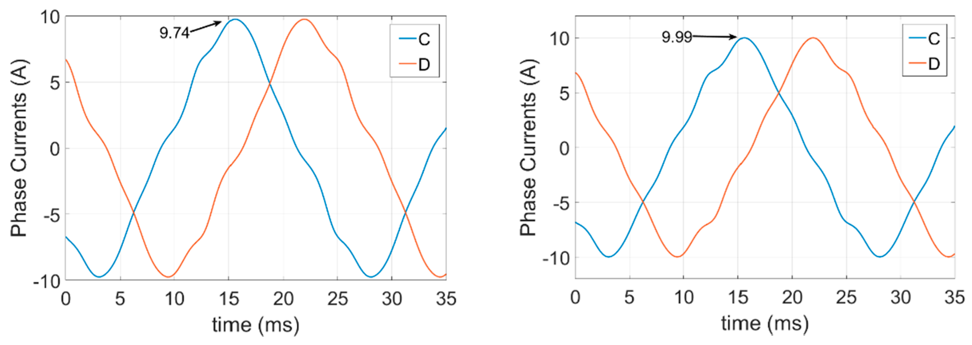
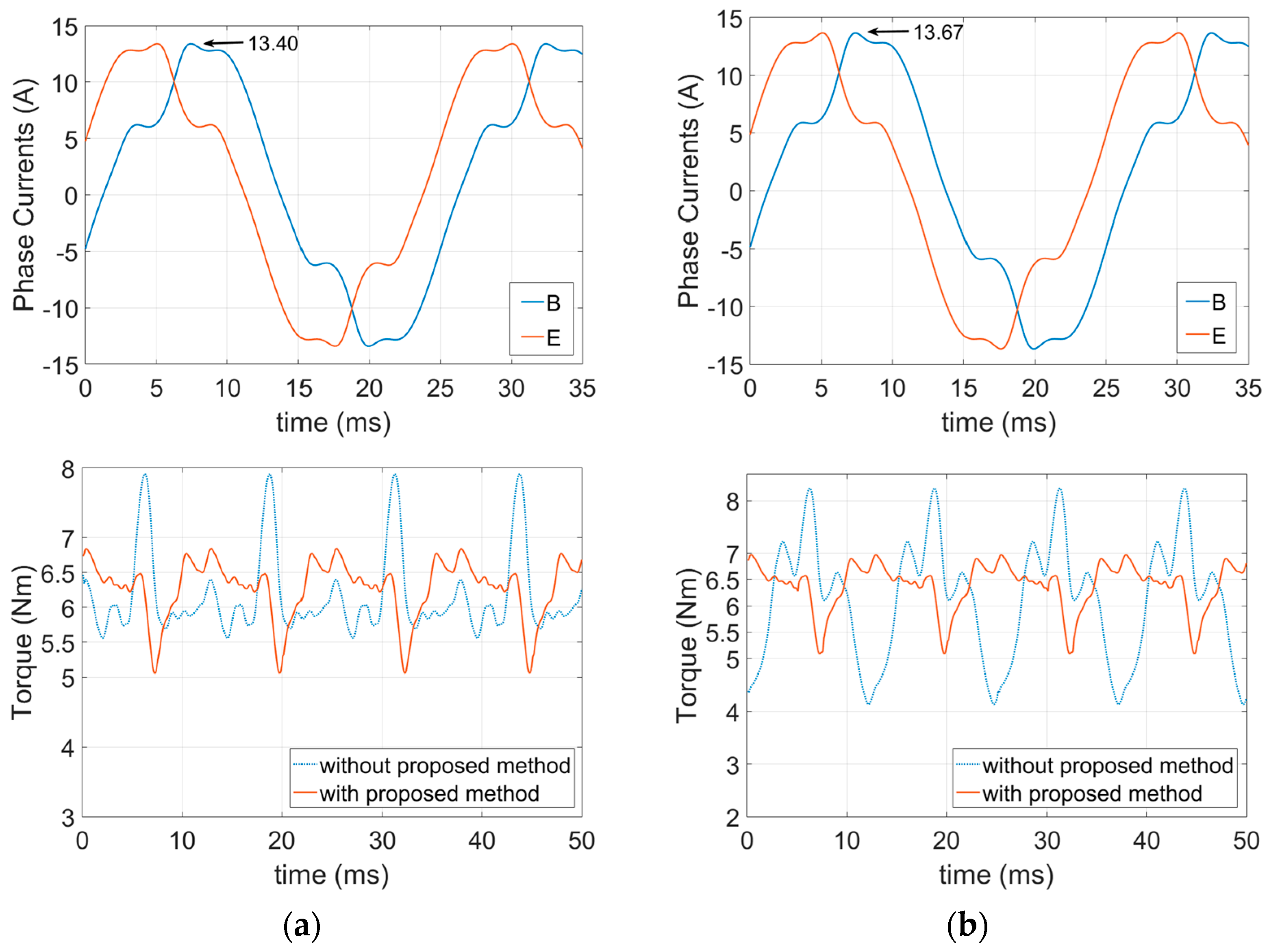
6.2. FEA Simulations of the Open-Circuit Fault-Tolerant Conditions

In this section, the simulation of five OCFT conditions has been undertaken to validate the proposed method. Additional current component derived in (17) has been used to obtain the new set of currents for the OCFT conditions.
Torque ripples for the SPOC (Phase A open) and ADPOC (Phase A and B open) conditions have almost been removed. This can be clearly seen in Figure 12, Figure 13, Figure 14, Figure 15 and Figure 16. Torque ripples for the NADPOC (Phase A and C open) and ATPOC (Phase A, B, and E open) conditions have also been nearly eliminated by using the proposed method apart from small ripples occurring at eight times per revolution. For the NATPOC (A, C, and D open) condition, there are still huge torque ripples with the proposed method. However, the percentage of the torque ripples of the proposed method is better than without the proposed method. Moreover, the level of the average torque has been drawn higher.
Average torque values and the percentage of the ripples can be seen in Table 2. It is clear from Table 2 that the torque ripple has been reduced compared to the torque ripple obtained without the proposed method. It is also clear from Table 2 that the torque has been improved by injecting the third harmonic component of the phase currents into the coils of the five-phase PM machine, as well as the various higher order harmonics.

7. Conclusions

Pulsations caused by the higher-order back-EMF harmonics should be eliminated to obtain a nearly smooth torque. For this purpose, a method has been developed to reduce the torque ripples for both the healthy and the OCFT conditions in terms of the I-power approach by adding an additional current component to each phase.
In the healthy condition, the 9th and 11th harmonic of the back-EMF causes ripples in torque for the fundamental component of the phase currents. When the third harmonic current component is injected into the phase coils, there will be other interactions with the 7th and 13th back-EMF harmonics that cause ripples in the torque, as well. All the ripples produced by interaction with the higher-order back-EMF harmonics have the same frequency, which is ten times the fundamental component of the phase currents. An additional current component has been added to each phase current to reduce the torque ripples for the healthy condition.
For the OCFT conditions, there is also an interaction between the fundamental component of the phase current and the third harmonic of the back-EMF, and vice versa. However, in the healthy condition, the sum of the interaction between the fundamental current and the third harmonic back-EMF is zero. For OCFT conditions, the sum of the interaction between the fundamental and the third harmonic back-EMF and vice versa is not zero, and it will produce ripples in the torque. Preventing these interactions will reduce the torque ripples. Adding an additional current component to each phase prevented these unwanted interactions.
Only the cogging torque of the multiphase machine is left when the proposed method has been applied to the machine’s windings under the healthy condition. Also, ripples of the torque have been reduced for the SPOC and ADPOC fault-tolerant conditions like in the healthy condition. Torque results of the NADPOC and ATPOC conditions have been nearly eliminated apart from small ripples. For the NATPOC condition, there are still huge ripples. However, these ripples are smaller than those obtained without the proposed method.

Author Contributions

Conceptualization, A.A.; methodology, A.A. and P.L.; software, A.A. and P.L.; validation, A.A. and P.L.; formal analysis, A.A.; investigation, A.A.; writing—original draft preparation, A.A.; writing—review and editing, A.A. and P.L.; visualization, A.A.; supervision, P.L.; project administration, P.L.; funding acquisition, A.A. and P.L. All authors have read and agreed to the published version of the manuscript.

Funding

This research received no external funding.

Institutional Review Board Statement

Not applicable.

Informed Consent Statement

Not applicable.

Data Availability Statement

Data is contained within the article.

Conflicts of Interest

The authors declare no conflict of interest.

References

  1. Levi, E. Multiphase electric machines for variable-speed applications. IEEE Trans. Ind. Electron. 2008, 55, 1893–1909. [Google Scholar] [CrossRef]
  2. Levi, E. Advances in converter control and innovative exploitation of additional degrees of freedom for multiphase machines. IEEE Trans. Ind. Electron. 2015, 63, 433–448. [Google Scholar] [CrossRef] [Green Version]
  3. Parsa, L. On advantages of multi-phase machines. In Proceedings of the IECON 2005—31st Annual Conference of IEEE Industrial Electronics Society, Raleigh, NC, USA, 6–10 November 2005; p. 6. [Google Scholar]
  4. Huang, J.; Zheng, P.; Sui, Y.; Zheng, J.; Yin, Z.; Cheng, L. Third Harmonic Current Injection in Different Operating Stages of Five-Phase PMSM With Hybrid Single/Double Layer Fractional-Slot Concentrated Winding. IEEE Access 2021, 9, 15670–15685. [Google Scholar] [CrossRef]
  5. Cervone, A.; Slunjski, M.; Levi, E.; Brando, G. Optimal Third-Harmonic Current Injection for Asymmetrical Multiphase Permanent Magnet Synchronous Machines. IEEE Trans. Ind. Electron. 2021, 68, 2772–2783. [Google Scholar] [CrossRef] [Green Version]
  6. Slunjski, M.; Jones, M.; Levi, E. Control of a symmetrical nine-phase PMSM with highly non-sinusoidal back-electromotive force using third harmonic current injection. In Proceedings of the IECON 2019—45th Annual Conference of the IEEE Industrial Electronics Society, Lisbon, Portugal, 14–17 October 2019; Volume 1, pp. 969–974. [Google Scholar]
  7. Zhang, L.; Wang, K.; Sun, H.; Zhu, S. Multiphase PM machines with Halbach array considering third harmonic flux density. IEEE Trans. Ind. Electron. 2018, 66, 9184–9193. [Google Scholar] [CrossRef]
  8. Wang, K.; Zhang, J.; Gu, Z.; Sun, H.; Zhu, Z. Torque improvement of dual three-phase permanent magnet machine using zero sequence components. IEEE Trans. Magn. 2017, 53, 1–4. [Google Scholar] [CrossRef]
  9. Sui, Y.; Zheng, P.; Fan, Y.; Zhao, J. Research on the vector control strategy of five-phase permanent-magnet synchronous machine based on third-harmonic current injection. In Proceedings of the 2017 IEEE International Electric Machines and Drives Conference (IEMDC), Miami, FL, USA, 21–24 May 2017; pp. 1–8. [Google Scholar] [CrossRef]
  10. Zimmermann, M.; Centner, M.; Stiebler, M. Five-phase permanent magnet synchronous machine under consideration of the third current harmonic. In Proceedings of the 2016 XXII International Conference on Electrical Machines (ICEM), Lausanne, Switzerland, 4–7 September 2016; pp. 2784–2788. [Google Scholar]
  11. Scuiller, F.; Zahr, H.; Semail, E. Maximum reachable torque, power and speed for five-phase SPM machine with low armature reaction. IEEE Trans. Energy Convers. 2016, 31, 959–969. [Google Scholar] [CrossRef]
  12. Scuiller, F. Magnet shape optimization to reduce pulsating torque for a five-phase permanent-magnet low-speed machine. IEEE Trans. Magn. 2013, 50, 1–9. [Google Scholar] [CrossRef] [Green Version]
  13. Parsa, L.; Toliyat, H.A. Five-phase permanent-magnet motor drives. IEEE Trans. Ind. Appl. 2005, 41, 30–37. [Google Scholar] [CrossRef]
  14. Toliyat, H.A.; Rahimian, M.M.; Lipo, T. dq modeling of five phase synchronous reluctance machines including third harmonic of air-gap MMF. In Proceedings of the Conference Record of the 1991 IEEE Industry Applications Society Annual Meeting, Dearborn, MI, USA, 28 September–4 October 1991; pp. 231–237. [Google Scholar]
  15. Levi, E.; Barrero, F.; Duran, M.J. Multiphase machines and drives—Revisited. IEEE Trans. Ind. Electron. 2016, 63, 429–432. [Google Scholar] [CrossRef] [Green Version]
  16. Jones, M.; Levi, E.; Vukosavic, S.; Toliyat, H. Independent vector control of a seven-phase three-motor drive system supplied from a single voltage source inverter. In Proceedings of the PESC’03—IEEE 34th Annual Conference on Power Electronics Specialist, Acapulco, Mexico, 15–19 June 2003; Volume 4, pp. 1865–1870. [Google Scholar]
  17. Levi, E.; Iqbal, A.; Vukosavic, S.; Toliyat, H. Modeling and control of a five-phase series-connected two-motor drive. In Proceedings of the IECON’03—29th Annual Conference of the IEEE Industrial Electronics Society (IEEE Cat. No. 03CH37468), Roanoke, VA, USA, 2–6 November 2003; Volume 1, pp. 208–213. [Google Scholar]
  18. Jones, M.; Vukosavic, S.N.; Levi, E.; Iqbal, A. A novel six-phase series-connected two-motor drive with decoupled dynamic control. In Proceedings of the Conference Record of the 2004 IEEE Industry Applications Conference—39th IAS Annual Meeting, Seattle, WA, USA, 3–7 October 2004; Volume 1. [Google Scholar]
  19. Levi, E.; Jones, M.; Vukosavic, S.N.; Toliyat, H.A. A novel concept of a multiphase, multimotor vector controlled drive system supplied from a single voltage source inverter. IEEE Trans. Power Electron. 2004, 19, 320–335. [Google Scholar] [CrossRef]
  20. Jones, M.; Vukosavic, S.; Levi, E. Combining induction and permanent magnet synchronous machines in a series-connected six-phase vector-controlled two-motor drive. In Proceedings of the 2005 IEEE 36th Power Electronics Specialists Conference, Dresden, Germany, 16 June 2005; pp. 2691–2697. [Google Scholar]
  21. Levi, E.; Jones, M.; Vukosavic, S.N. A series-connected two-motor six-phase drive with induction and permanent magnet machines. IEEE Trans. Energy Convers. 2006, 21, 121–129. [Google Scholar] [CrossRef]
  22. Levi, E.; Jones, M.; Vukosavic, S.N.; Iqbal, A.; Toliyat, H.A. Modeling, control, and experimental investigation of a five-phase series-connected two-motor drive with single inverter supply. IEEE Trans. Ind. Electron. 2007, 54, 1504–1516. [Google Scholar] [CrossRef]
  23. Parsa, L.; Toliyat, H.A. Fault-tolerant five-phase permanent magnet motor drives. In Proceedings of the Conference Record of the 2004 IEEE Industry Applications Conference—39th IAS Annual Meeting, Seattle, WA, USA, 3–7 October 2004; Volume 2, pp. 1048–1054. [Google Scholar] [CrossRef]
  24. Dwari, S.; Parsa, L. An Optimal Control Technique for Multiphase PM Machines Under Open-Circuit Faults. IEEE Trans. Ind. Electron. 2008, 55, 1988–1995. [Google Scholar] [CrossRef]
  25. Dwari, S.; Parsa, L. Fault-Tolerant Control of Five-Phase Permanent-Magnet Motors With Trapezoidal Back EMF. IEEE Trans. Ind. Electron. 2011, 58, 476–485. [Google Scholar] [CrossRef]
  26. Mohammadpour, A.; Sadeghi, S.; Parsa, L. A generalized fault-tolerant control strategy for five-phase PM motor drives considering star, pentagon, and pentacle connections of stator windings. IEEE Trans. Ind. Electron. 2013, 61, 63–75. [Google Scholar] [CrossRef]
  27. Mohammadpour, A.; Parsa, L. Global fault-tolerant control technique for multiphase permanent-magnet machines. IEEE Trans. Ind. Appl. 2014, 51, 178–186. [Google Scholar] [CrossRef]
  28. Zhao, J.; Gao, X.; Li, B.; Liu, X.; Guan, X. Open-phase fault tolerance techniques of five-phase dual-rotor permanent magnet synchronous motor. Energies 2015, 8, 12810–12838. [Google Scholar] [CrossRef]
  29. Sui, Y.; Zheng, P.; Yin, Z.; Wang, M.; Wang, C. Open-circuit fault-tolerant control of five-phase PM machine based on reconfiguring maximum round magnetomotive force. IEEE Trans. Ind. Electron. 2018, 66, 48–59. [Google Scholar] [CrossRef]
  30. Islam, R.; Husain, I.; Fardoun, A.; McLaughlin, K. Permanent-Magnet Synchronous Motor Magnet Designs With Skewing for Torque Ripple and Cogging Torque Reduction. IEEE Trans. Ind. Appl. 2009, 45, 152–160. [Google Scholar] [CrossRef]
  31. Flieller, D.; Nguyen, N.K.; Wira, P.; Sturtzer, G.; Abdeslam, D.O.; Mercklé, J. A self-learning solution for torque ripple reduction for nonsinusoidal permanent-magnet motor drives based on artificial neural networks. IEEE Trans. Ind. Electron. 2013, 61, 655–666. [Google Scholar] [CrossRef] [Green Version]
  32. Gómez-Espinosa, A.; Hernández-Guzmán, V.M.; Bandala-Sánchez, M.; Jiménez-Hernández, H.; Rivas-Araiza, E.A.; Rodríguez-Reséndiz, J.; Herrera-Ruíz, G. A new adaptive self-tuning Fourier coefficients algorithm for periodic torque ripple minimization in permanent magnet synchronous motors (PMSM). Sensors 2013, 13, 3831–3847. [Google Scholar] [CrossRef] [PubMed]
  33. Zheng, Z.; Sun, D.; Zhu, J. Torque ripple suppression of open-winding PMSMs by current injection considering magnetic saturation. In Proceedings of the 2016 IEEE Vehicle Power and Propulsion Conference (VPPC), Hangzhou, China, 17–20 October 2016; pp. 1–5. [Google Scholar]
  34. He, K.; Zhu, W.; Xu, L. Research on Torque Ripple Suppression of Permanent Magnet Synchronous Motor. IOP Conf. Ser. Earth Environ. Sci. 2018, 170, 042129. [Google Scholar] [CrossRef]
  35. Li, J.; Li, X.; Zhang, Y.; Gui, X. Torque Ripple Suppression Based Fast Harmonics Decomposition. In Proceedings of the 2019 22nd International Conference on Electrical Machines and Systems (ICEMS), Harbin, China, 11–14 August 2019; pp. 1–6. [Google Scholar] [CrossRef]
  36. Liang, Q.; Wei, F.; Li, Z.; Deng, Y.; Wang, Y. Torque Ripple Suppression of Permanent Magnet Synchronous Motor Based On Robust Current Injection. IOP Conf. Ser. Mater. Sci. Eng. 2020, 782, 032082. [Google Scholar] [CrossRef] [Green Version]
  37. Wang, K.; Gu, Z.; Zhu, Z.; Wu, Z. Optimum injected harmonics into magnet shape in multiphase surface-mounted PM machine for maximum output torque. IEEE Trans. Ind. Electron. 2017, 64, 4434–4443. [Google Scholar] [CrossRef]
  38. Bianchi, N.; Bolognani, S. Design techniques for reducing the cogging torque in surface-mounted PM motors. IEEE Trans. Ind. Appl. 2002, 38, 1259–1265. [Google Scholar] [CrossRef]
  39. Parsa, L.; Hao, L. Interior Permanent Magnet Motors With Reduced Torque Pulsation. IEEE Trans. Ind. Electron. 2008, 55, 602–609. [Google Scholar] [CrossRef]
  40. Yan, L.; Liao, Y.; Lin, H.; Sun, J. Torque ripple suppression of permanent magnet synchronous machines by minimal harmonic current injection. IET Power Electron. 2019, 12, 1368–1375. [Google Scholar] [CrossRef]
  41. Jędryczka, C.; Danielczyk, D.; Szeląg, W. Torque Ripple Minimization of the Permanent Magnet Synchronous Machine by Modulation of the Phase Currents. Sensors 2020, 20, 2406. [Google Scholar] [CrossRef] [Green Version]
  42. Arafat, A.; Choi, S. Active current harmonic suppression for torque ripple minimization at open-phase faults in a five-phase PMa-SynRM. IEEE Trans. Ind. Electron. 2018, 66, 922–931. [Google Scholar] [CrossRef]
  43. Guo, Y.; Wu, L.; Huang, X.; Fang, Y.; Liu, J. Adaptive Torque Ripple Suppression Methods of Three-Phase PMSM During Single-Phase Open-Circuit Fault-Tolerant Operation. IEEE Trans. Ind. Appl. 2020, 56, 4955–4965. [Google Scholar] [CrossRef]
  44. Akay, A.; Lefley, P. Research on torque ripple under healthy and open-circuit fault-tolerant conditions in a PM multiphase machine. CES Trans. Electr. Mach. Syst. 2020, 4, 349–359. [Google Scholar] [CrossRef]
Figure 1. Phasor diagram of the phase current components: (a) Fundamental; (b) third harmonic.
Energies 14 02615 g001
Figure 2. Back-EMF waveform of the simulated five-phase PM machine “Reprinted from Publisher, 2021 [44]”.
Energies 14 02615 g002
Figure 3. I-power with and without proposed method: (a) Considering all the back-EMF harmonics; (b) considering the harmonics that cause ripples.
Energies 14 02615 g003
Figure 4. I-power graphs for the single-phase OCFT condition currents: (a) Fundamental; (b) fundamental plus third harmonic.
Energies 14 02615 g004
Figure 5. I-power graphs for the adjacent double-phase OCFT condition currents: (a) Fundamental; (b) fundamental plus third harmonic.
Energies 14 02615 g005
Figure 6. I-power graphs for the nonadjacent double-phase OCFT condition currents: (a) Fundamental; (b) fundamental plus third harmonic.
Energies 14 02615 g006
Figure 7. I-power graphs for the adjacent three-phase OCFT condition currents: (a) Fundamental; (b) fundamental plus third harmonic.
Energies 14 02615 g007
Figure 8. I-power graphs for the nonadjacent three-phase OCFT condition currents: (a) Fundamental; (b) fundamental plus third harmonic.
Energies 14 02615 g008
Figure 9. Simulated five-phase PM machine: (a) FEA model “Reprinted from Publisher, 2021 [44]”; (b) Cogging torque.
Energies 14 02615 g009
Figure 10. FEA torque waveforms for the Healthy1 condition with and without proposed method: (a) Only fundamental; (b) fundamental plus third harmonic.
Energies 14 02615 g010
Figure 11. FEA torque waveforms for the Healthy2 condition with and without proposed method: (a) Only fundamental; (b) fundamental plus third harmonic.
Energies 14 02615 g011
Figure 12. FEA torque waveforms for the fault-tolerant control currents of the SPOC condition with and without proposed method: (a) Only fundamental; (b) fundamental plus third harmonic.
Energies 14 02615 g012
Figure 13. FEA torque waveforms for the fault-tolerant control currents of the ADPOC condition with and without the proposed method: (a) Only fundamental; (b) fundamental plus third harmonic.
Energies 14 02615 g013aEnergies 14 02615 g013b
Figure 14. FEA torque waveforms for the fault-tolerant control currents of the NADPOC condition with and without the proposed method: (a) Only fundamental; (b) fundamental plus third harmonic.
Energies 14 02615 g014
Figure 15. FEA torque waveforms for the fault-tolerant control currents of the ATPOC condition with and without the proposed method: (a) Only fundamental; (b) fundamental plus third harmonic.
Energies 14 02615 g015aEnergies 14 02615 g015b
Figure 16. FEA torque waveforms for the fault-tolerant control currents of the NATPOC condition with and without proposed method: (a) Only fundamental; (b) fundamental plus third harmonic.
Energies 14 02615 g016
Table 1. Parameters of The Five-Phase PM Machine “Reprinted from Publisher, 2021 [44]”.
Rated Power (kW)1
Rated Speed (rpm)2000
Rated Current (Amps)(Peak)3.39
Rated Torque (Nm)6.6966
Number of Poles8
Number of slots10
Table 2. FEA average torque results and ripples.
Only Fundamental CurrentFundamental + Third Harmonic Current
without Proposed Methodwith Proposed Methodwithout Proposed Methodwith Proposed Method
AverageRipple (%)AverageRipple (%)AverageRipple (%)AverageRipple (%)
Healthy16.69647.19346.69435.06406.82338.42996.81795.0705
Healthy26.69647.19346.69425.04176.82338.42996.81895.0399
A Open6.672119.72496.67536.79306.777244.51196.80096.9170
A and B Open6.688915.36996.68695.56726.807578.01806.81425.4545
A and C Open6.503223.47506.551513.53746.582934.53356.668913.7595
A, B and E Open6.504222.41546.548113.33046.5873108.13076.661613.8070
A, C and D Open6.168038.29066.274428.56546.108067.13716.380029.5695
Publisher’s Note: MDPI stays neutral with regard to jurisdictional claims in published maps and institutional affiliations.

