Article

Energy Efficient Parallel Configuration Based Six Degree of Freedom Machining Bed

1
Department of Mechatronics and Biomedical Engineering, Air University, Islamabad 44000, Pakistan
2
Department of Mechanical Engineering, Khwaja Fareed University of Engineering and IT, Rahim Yar Khan 64200, Pakistan
3
Department of Control Science and Engineering, School of Automation, Beijing Institute of Technology, Beijing 100081, China
4
Innovative Educational Technologies, Andijan Machine Building Institute, Andizhan 170100, Uzbekistan
5
Department of Intelligent Systems and Control Engineering, School of Automation Science and Electrical Engineering, Beihang University, Beijing 100191, China
6
School of Mechanical, Aerospace and Automotive Engineering, Faculty of Engineering, Environmental and Computing, Coventry University, Coventry CV1 5FB, UK
*
Authors to whom correspondence should be addressed.
Energies 2021, 14(9), 2642; https://doi.org/10.3390/en14092642
Submission received: 20 March 2021 / Revised: 29 April 2021 / Accepted: 29 April 2021 / Published: 5 May 2021
(This article belongs to the Special Issue Biofuels and Sustainable Energy Materials Development)

Abstract

:
The process of material removal from a workpiece to obtain the desired shape is termed machining. Present-day material removal technologies have high spindle speeds and thus allow quick material removal. These high-speed spindles are highly exposed to vibrations and, as a result, the accuracy of the final workpiece’s dimensions is compromised. To overcome this problem, the motion of the tool is restricted, and multiple degrees of freedom are given through the motion of the workpiece in different axes. A machining bed configured as a parallel manipulator capable of giving six degrees of freedom (DOF) to the workpiece is proposed in this regard. However, the proposed six DOF machining bed should be energy efficient to avoid an increase in machining cost. The benefit of using the proposed configuration is a reduction in dimensional error and computational time which, as a result, reduces the energy utilization, vibrations, and machining time in practice. This paper presents kinematics, dynamics and energy efficiency models, and the development of the proposed configuration of the machining bed. The energy efficiency model is derived from the dynamics model. The models are verified in simulation and experimentally. To minimize error and computation time, a PID controller is also designed and tested in simulation as well as experimentally. The resulting energy efficiency is also analyzed. The results verify the efficacy of the proposed configuration of the machining bed, minimizing position error to 2% and reducing computation time by 27%, hence reducing the energy consumption and enhancing the energy efficiency by 60%.

1. Introduction

The machining technologies available today allow very high spindle speeds and hence the material is removed very quickly [1]. These high spindle speeds are vulnerable to internal and external vibrations and thus the accuracy of the product is compromised [2]. A solution to this problem is to restrict the motion of the tool and give motion to the workpiece, contrary to the current CNC machining techniques [3]. For this purpose, a parallel manipulator configuration having the capability to give six degrees of freedom is proposed in this study. However, the proposed six DOF machining bed should be energy efficient to avoid increase in machining cost.
The proposed mechanism is given the name of the machining bed. Such a parallel mechanism was first designed by Gough and Stewart [4]. These kinds of manipulators are widely known for their high stiffness and rigidity when compared to serial manipulators [5]. The early work on the Gough and Stewart Platform was performed for its applications in the flight simulation industry, the original purpose for which this design was built [6]. In recent years parallel manipulators have gained a lot of attention from the research community and the industrial sector as well. These manipulators are now being widely used in various applications such as precision surgery [7] and simulators for different devices [8].
The hurdle in using the parallel mechanisms of manipulators is their limited workspace [9], and difficulty in solving the kinematics of these manipulators [10]. Due to insufficient lower-dimensional spaces, it becomes difficult to solve the kinematics problems for parallel manipulators [11]. Hung et al. proposed the solution for the closed-form kinematics chain of the Stewart Platform [12]. Liu et al. gave the numerical algorithm to solve the kinematics problem of the parallel manipulators using the simultaneous equation method [13]. Hrib et al. presented a numerical iterative scheme to evaluate the kinematics of parallel manipulators-based machine tools [14]. The geometric method for solving the kinematics of the planar parallel robots was studied by Yang et al. [15]. Inverse kinematics for parallel manipulators using the graphical method and vector addition method are presented in [16] and [17], respectively. The screw theory method [18] and the Newton Raphson method [19] are also used in the literature to solve the kinematics problem of the parallel manipulators [20]. Developing a dynamic model for parallel manipulators is also a tedious and complicated task [21]. Most of the researchers have used the Lagrange method [22], the Newton Euler Method [23], and the principle of virtual work [24] to develop the dynamic model for the parallel manipulators [25,26,27,28]. The driving force for the Platform by neglecting the leg inertia is presented by Fichter [29]. This study proved to be helpful in many applications of parallel mechanisms as there are many applications in which the leg forces are negligible [30]. For practical implementation, however, legs have inertia, which demands more power for their motion and this ultimately increases the energy demand.
The energy efficiency of parallel manipulators has been the subject of many studies. Li and Bone in their study demonstrated that parallel manipulators can be more highly energy-efficient than serial manipulators [31]. For a 3(P) RRR manipulator, an energy optimization was proposed by Pasand et al. [32]. Kuck proposed an algorithm to optimize the masses of the links and end effector of the parallel manipulator to achieve low power consumption [33]. Scaleara et al., studied the dynamic and electromechanical models to analyze the energy consumption [34]. However, these studies are for parallel manipulators with up to 4 DOF, whereas the parallel manipulator proposed here for the machining bed has 6 DOF. The objective of this research, therefore, is to design an algorithm and methodology to analyze energy efficiency of the 6DOF parallel manipulator, proposed for the machining bed. The approach used in this research to achieve the objective is two staged, as follows:
  • The dynamics of the proposed machining bed is presented in detail to formulate the energy efficiency model.
  • An algorithm is proposed to reduce the computation time for the calculation of the leg lengths of the machining bed, which reduces the energy consumed.
The flow chart for the methodology of the research is shown in Figure 1. The breakdown of the paper is as follows:
  • Section 2 describes the mechanism of the proposed machining bed. The configuration of the mechanism is presented
  • Section 3 presents the mathematical model for the machining bed. This section presents the kinematics model and the dynamics model of the machining bed. Using the dynamics model the energy efficiency model developed is also discussed in this section.
  • Section 4 presents the verification of models in simulation
  • Section 5 discusses the controller design for the machining bed to minimize the effects of overshoot and error obtained
  • Section 6 discusses the fabrication of the proposed machining bed. This section also presents the experimental testing of the developed machining bed for model validation presented in Section 3 and Section 5.

2. Mechanism Description

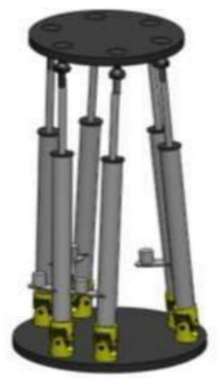
The proposed mechanism mainly consists of a movable top plate, a fixed base plate, and linear actuators. The linear actuators are connected to the fixed base plate by universal joints and with the movable top plate by ball and socket joints. This combination of ball and socket joint, linear actuator, and universal joint forms a kinematic chain. The mechanism consists of six kinematic chains and hence can give six degrees of freedom motion. Both translational and rotational motions are associated with the machining bed. The proposed machining bed can give three translational motions in the X, Y, and Z axes and three rotational motions—roll, pitch, and yaw. The software model of the machining bed is shown in Figure 2. For such parallel manipulators, many configurations have been proposed in the literature [35]. An overview from selected studies is given in Table 1. The machining bed is designed in a 6–3 configuration. The kinematic chains are attached at an equal angle at the movable top plate. At the base plate, the kinematic chains are attached at three different points with two legs connected adjacently. The schematic representation of kinematic chain connections and angle distribution on the top and base plate is shown in Figure 3.
For simplicity, it was assumed that there are no actuator constraints, leg interfaces, or singularities in the mechanism.

3. Modeling

3.1. Kinematics Model of the Machining Bed

Kinematics refers to the study of the motion of the body without regard to forces. Generally, kinematics is categorized as forward and inverse kinematics. In inverse kinematics, the position of the end effector is known, and the leg lengths are found accordingly. For parallel manipulators developing the inverse kinematics model is simpler as compared to forward kinematics [41]. For simplicity, all legs of the machining bed were considered to be identical. A schematic diagram for the ith leg of the machining bed is shown in Figure 3. Using the vector addition method and head and tail rule, the equation for the ith leg of the machining bed is written as in Equation (1). A description of the symbols used in the equation can be seen in the nomenclature list given at the end of the manuscript. The distribution of legs on the movable top plate and a fixed base plate is shown in Figure 4. Each leg is attached to the movable top plate at an equal angle of 60°. Using Equation (1), and angle information from Figure 4, a kinematic equation for each leg was obtained. Equation (2) shows the rotation matrix for the movable top plate. In Equations (3)–(8), “r” is the radius of the movable top plate, “R” is the radius of the fixed base plate, “c” and “s” represent cosine and sine angles, respectively and ψ , θ , and ω are the angles in x, y, and z-axis, respectively.
L i = V t + B P R X p X b
( B P ) R = R Z ( ψ ) R Y ( θ ) R X ( ω )
L 1 = r c ψ c θ R c 12.5 r s ψ c θ R c 12.5 a r s θ
L 2 =          r c 60 c ψ c θ r s 60 s ψ s ω + r s 60 c ψ s θ s ω R c 47.5 r c 60 s ψ c θ r s 60 c ψ c ω r s 60 s ψ s ω s θ R s 47.5 a r c 60 s θ + r s 60 c θ s ω
L 3 =      r c 60 c ψ c θ r s 60 s ψ s ω + r s 60 c ψ s θ s ω +   R c 47.5 r c 60 s ψ c θ + r s 60 c ψ c ω + r s 60 s ω s ψ s θ R s 47.5 a + r c 60 s θ + r s 60 c θ s ω
L 4 = r c ψ c θ + R c 12.5 r s ψ c θ R s 12.5 a + r s θ
L 5 = r c 60 c ψ c θ + r s 60 s ψ c ω + r s 60 c ψ s θ s ω + R c 17.5 r c 60 s ψ c θ r s 60 c ψ c 60 r s 60 s φ s ψ s θ + R s 17.5 a + r c 60 s θ r s 60 c θ s ω
L 6 =   r c 60 c ψ c θ + r s 60 s ψ c ω r s 60 c ψ s θ s ω R c 17.5 r c 60 s ψ c θ r s 60 c ψ c 60 r s 60 s ω s ψ s θ + R s 17.5 a r c 60 s θ r s 60 c θ s ω

3.2. Dynamics Model

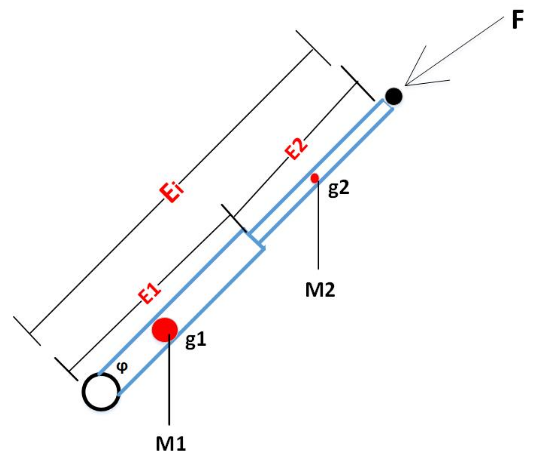
The machining bed is a special case of a closed chain mechanism. To control the machining bed, a formulation that is specific for such mechanisms was studied. For a single leg, the free body diagram is shown in Figure 5. Both translational and rotational energies comprise the total kinetic energy of the machining bed. For the moving top plate of the machining bed, the translational and rotational kinetic energies are given as in Equations (9) and (10), where f x , f y and f z are the positions in the x, y, and z axes, respectively. Potential energy for the movable top plate is given by Equation (11).
K t r a n s = 1 2 M f x     2 f y 2    f z 2
K r o t = 1 2 V i T I m V i   
P = 0   0   m p g   0   0   0   P x P y P z f x f y f z  
The machining bed consists of six kinematic chains, referred to as the machining bed legs. The leg of the machining bed consists of a linear actuator, universal joint, and ball and socket joint. The linear actuator consists of two parts: one is stationary and the other is movable. This movable part of the linear actuator produces different leg lengths. A description of the symbols can be found in the nomenclature section of this paper. The total kinetic energy of the leg can be written as given in Equation (12). The total potential energy of the leg is shown in Equation (16).
K i = 1 2      M 1 + M 2   V i T h i V T J L i Q i L i
where
h i = I E i + M 2 M 1 + M 2 2
And,
I = 1 M 1 + M 2 Δ M 1 E 1 1 2 M 2 E 2
And,
Q i = h i ( M 2 M 2 M 1 )
P l e g s = ( M 1 + M 2 ) g i = 1 6 { I 1 E 2 i + 1 E 2 i 1 + 2 M 2 M 1 + M 2 }

3.3. Dynamics Modelling of the Linear Actuator

In comparison to the rotational motion produced by a DC motor, the actuator that has the potential to produce motion in the straight line is known as a linear actuator. Generally, in a current-carrying armature, the speed and the voltage produced are related as given in Equation (17).
V b t = k b d θ m t d t    
In Equation (17), kb is the constant of proportionality. Laplace transform of Equation (17) yields Equation (18),
V b s = K b s θ m s
The armature current Ia, applied armature voltage Ea, and back electromotive force can be related as shown in Equation (19).
R a I a s + L a s I a s + V b s = E a s       
where Ra is the resistance, La is the inductance. The torque produced by the motor is proportional to the armature current as given in Equation (20). Kt is the constant of proportionality.
T m s = K t I a s   
Substituting Equations (18) and (20) in (19) yields Equation (21).
R a + L a s T m s K t + K b s θ m s = E a s
To obtain the transfer function θ m s E a s , T m s is calculated in terms of θ m s Figure 6 shows a conventional equivalent mechanical loading on a motor. “J” is the equivalent inertia of the motor.
D” is the equivalent viscous damping at the armature. It includes both the armature viscous damping.
T m s = J s 2 + D s   θ m s
Solving Equations (21) and (22) yields,
R a + L a s J s 2 + D s   θ m s K t + K b s θ m s = E a s
Assuming that L a is small in comparison to R a which is typical for a dc motor, so Equation (24) gives,
R a K t J s + D + K b   s θ m s = E a s
Simplifying Equation (24) gives transfer function as shown in Equations (25) and (26).
θ m s E a s = K t R a J s s + 1 J D + K t K b R a   
θ m s E a s = K t R a J   s 2 + R a D + K t K b  
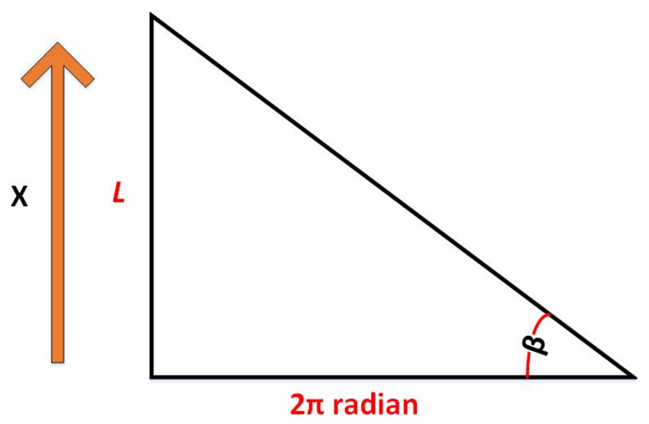
Figure 7 shows the relationship between the angular advance produced by the motor and the linear advance after the ball screw. In Figure 6, β represents the angle of the ball-screw lead l represents the step of the lead, and x(t) represents the linear advance.
x t = L 2 π θ m t
In Equation (27)   θ m t is in radians. It represents the angular advance generated by the motor. Therefore, Equation (27) yields,
θ m t = 2 π   x t L   
So,
X s E a s = L K t 2 π R a J   s 2 + R a D + K t K b s    
The transfer function obtained in Equation (29) was computed using MATLAB®. The values for mass and constants were used from the datasheet of a linear actuator.

3.4. Energy Efficiency Model

The dynamics model presented in Section 3.2 serves to give the required torque in each trajectory. Energy being consumed by each actuator can be computed as given in Equation (30).
E i = 0 t P i d t
For the proposed machining bed, the energy efficiency is the ratio of the output energy of the moving platform and the total energy of the machining bed. Using Equations (9) and (10), the total energy for the moving platform can be derived as given in Equation (31).
E m = K ( t r a s n ) + K ( r o t )
As mentioned in Section 2, the machining bed comprises joints and linear actuators. The total energy of the machining bed is the sum of the power required for the execution of machining. The total energy of the machining bed is given in Equation (32). The energy efficiency of the proposed machining bed is given by Equation (33).
E b = 0 t [ i = 1 6 f i ( t ) v i ( t ) +   i = 1 6 T m i ( t ) ω m i ( t ) ]
η = E m E b

4. Model Verification

4.1. Kinematics Model Verification

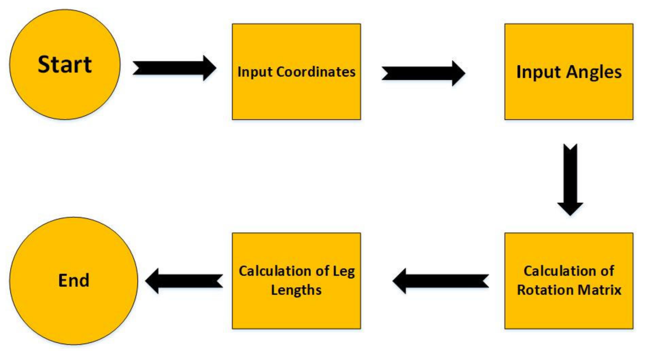
The kinematics model developed for the machining bed was verified in simulation using MATLAB®. The flow chart of the algorithm for solving the inverse kinematics of the machining bed is shown in Figure 8. As proposed in Section 3.1, the kinematics model presented can give the same lengths for any two legs of the machining bed for an arbitrary position. This hypothesis was verified by a case study. Initially, different sets of random coordinates were given. The leg lengths obtained for different coordinates are shown in Table 2. The results show that any two legs have the same value. The benefit of using this kinematics model is that the computation time is reduced and hence the machining time will also be reduced in practice.
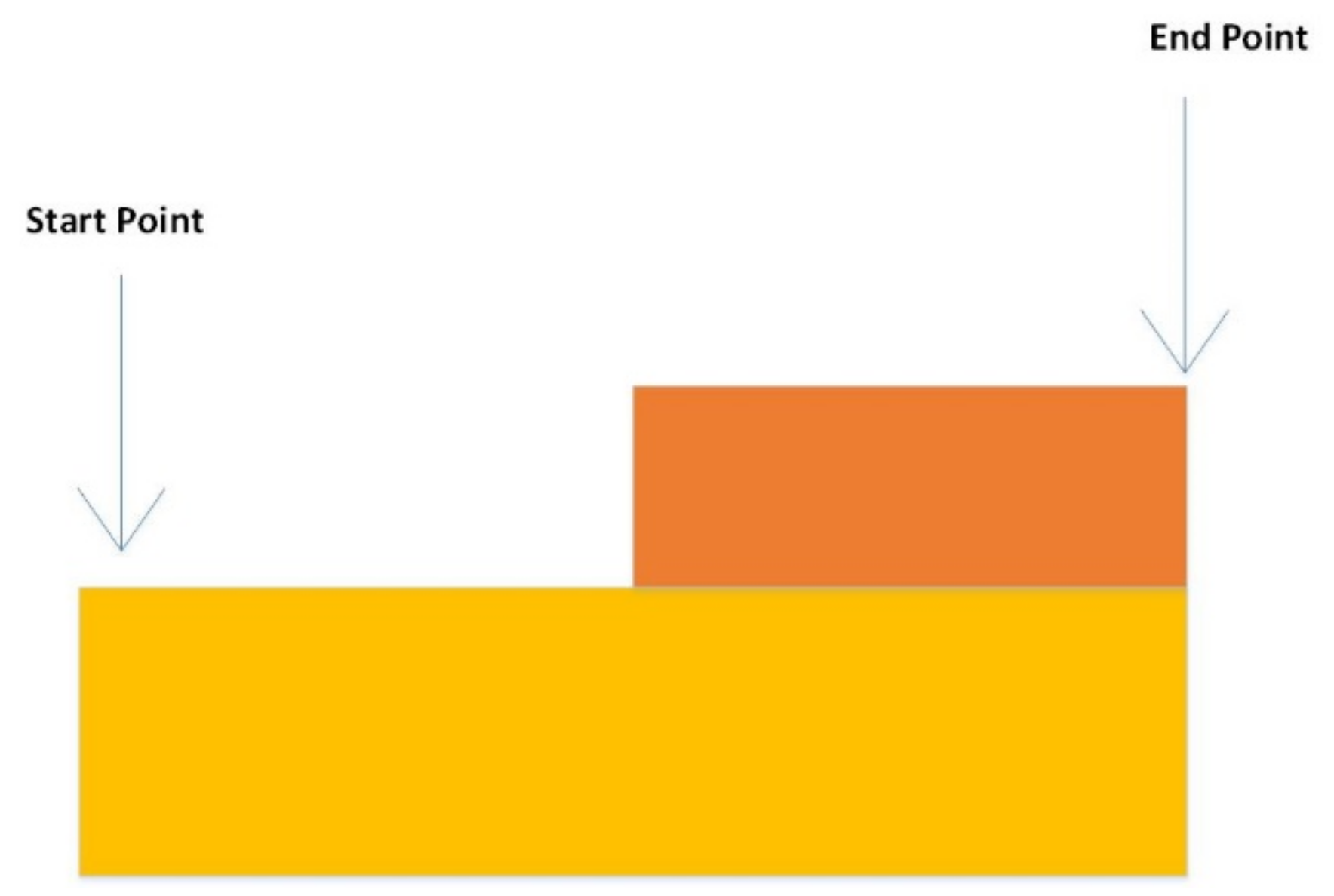
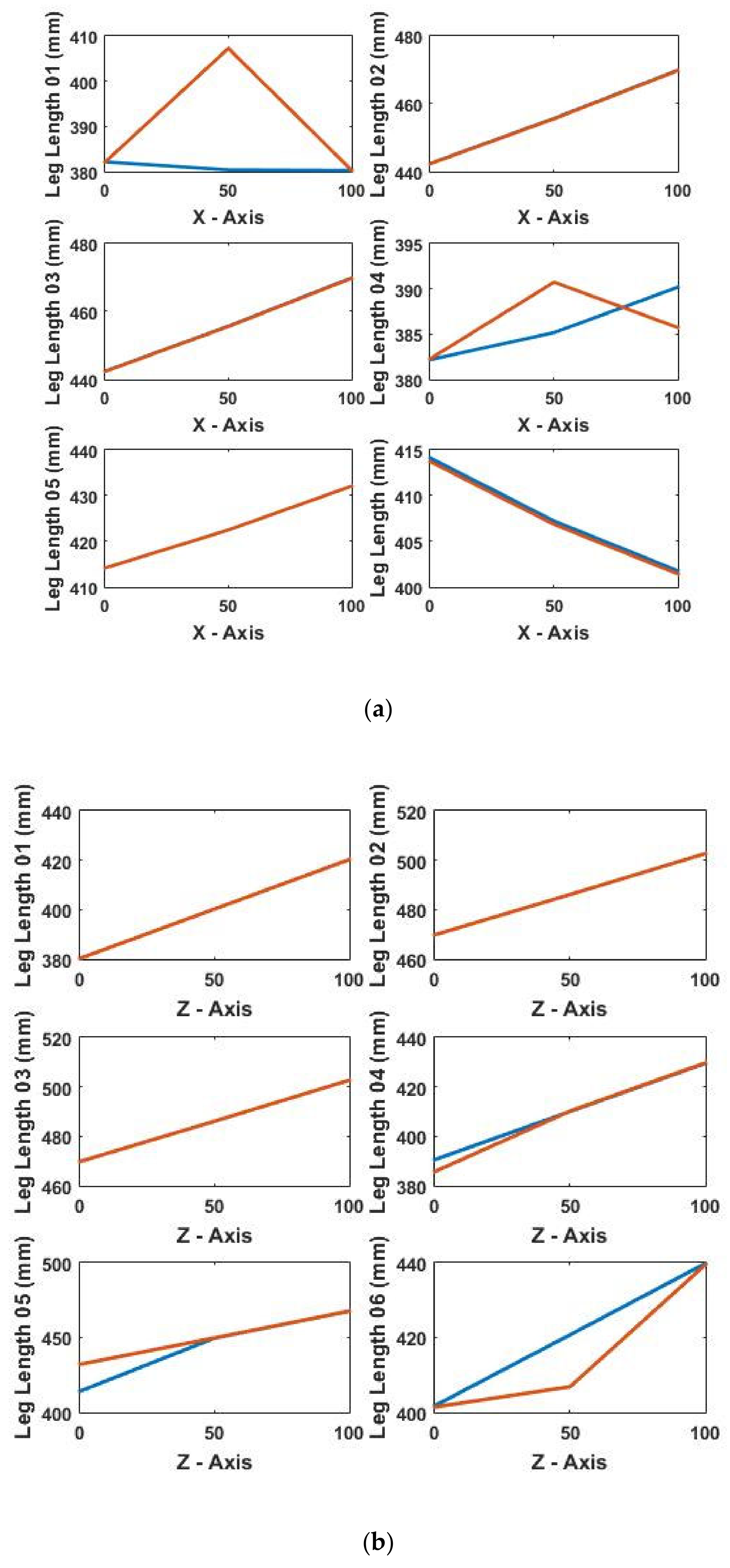
The kinematics model proposed was then tested through experiments in simulation for a workpiece. The schematic of the workpiece is shown in Figure 9. The machining process was divided into three steps. The description of these tests is given in Table 3. The first test was performed with the movement in X-axis only. The leg lengths obtained for this test are shown in Figure 10a–c. The results obtained show that leg 2 and leg 3 have the same value for every point for this test. The initial values for leg 1 and leg 4, leg 5 and leg 6 are the same.

4.2. Energy Efficiency Analysis

For the proposed workpiece, the energy efficiency was calculated using the dynamics model presented in Section 3.2 and Section 3.3 and the energy efficiency model presented in Section 3.4. The information provided in Table 3 was used to perform the simulations. For a given workpiece to be machined it was desired that the machining bed should be able to work at the highest energy efficiency possible in its workspace. Table 4 shows the results obtained for different tests. The energy consumed by the actuators, the moving platform and the machining bed is presented in Table 4. The energy efficiency achieved shows that for the given workpiece, the machining bed was able to achieve maximum of 60% efficiency. It was observed that high energy efficiency results in the high effective energy of the moving platform of the machining bed. The losses in energy during the transmission phase can also be controlled by higher energy efficiency.

5. Controller Design

5.1. Position Control

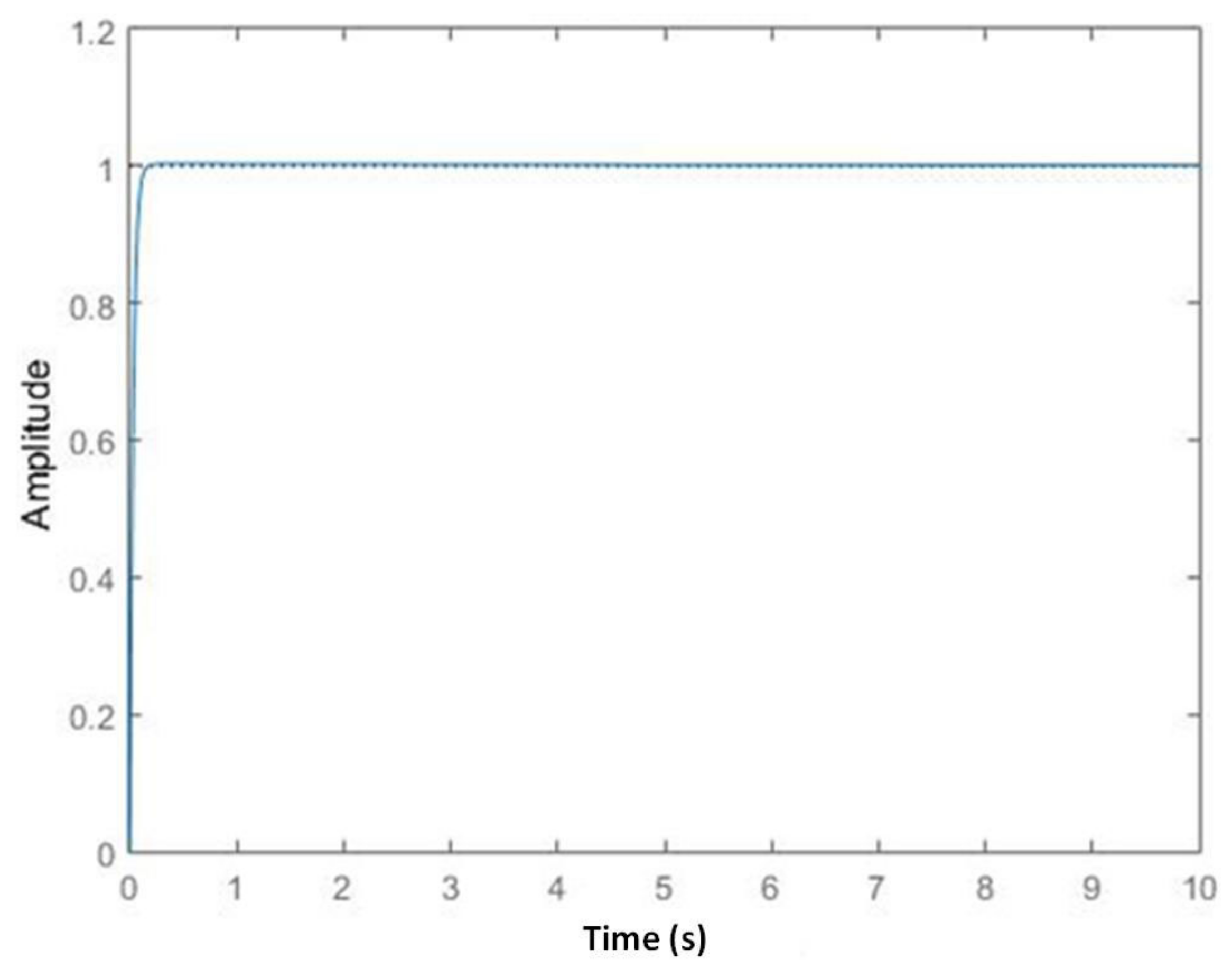
To verify the dynamics model for the machining bed obtained in Section 3, a closed-loop model was developed in SIMULINK, a toolbox of MATLAB®. A step input was given to the system to analyze the close loop response. Figure 11 presents the closed-loop response.
The rise time of the system is 0.0177 s, the settling time is observed to be 0.0842 s and a maximum peak amplitude of 1.15 is obtained at 0.0395 s. From Figure 10, it is evident that there is an overshoot in the close loop response of the machining bed. This overshoot is not desired in achieving the objective of machining.
To minimize the effect of the overshoot a Proportional-Integral-Derivative (PID) controller was designed. Simplicity in designing, ease of usage, and effortless implementation are the advantages of the PID controller, due to which this controller was selected [42]. In this controller, the process variables are controlled by a closed-loop mechanism. The PID controller corrects the error between the input parameter obtained from the feedback loop and the desired parameter. The output is then corrected to adjust the process [43]. The general form of the control law is given as in Equation (32), where Kp, Kd, and Ki are controller gains.
u ( t ) = K p e ( t ) + K i 0 t e ( T ) d t   + K d d e d t
In a PID controller, the proportional parameter influences the current error response. This decreases the rise time but not eliminates steady-state error completely. The integral parameter affects the response over time by summing up errors. The parameter derivative refers to the error change rate [44]. The effect of controller gains is shown in Table 5.
The objective for designing the controller was to control the position of the linear actuator minimizing the error. A feedback system is thus developed in SIMULINK. The schematic of the closed-loop system developed in SIMULINK is shown in Figure 12. The control law of the PID controller is based on the variable detected by the sensor, its time integral, and its first derivative. The plant has two main parts, the machining bed subsystem, and the controller subsystem. The machining bed subsystem consists of a parallel manipulator, actuators, and sensors, while the controller subsystem controls the motion of the machining bed. A predefined motion is fed into the plant and the controller assures the minimum error between the reference and actual trajectory. Reference trajectory to the plant was given using the leg reference trajectory system. For this machining bed, the sinusoidal wave is given as a reference trajectory. The reason for selecting this as a reference is to check the errors in the motion of the legs for complex shapes. This system was capable of handling any kind of reference trajectory. The response of the machining bed system to the PID controller is shown in Figure 13.

5.2. Computational Time Control

The graphical and vector addition method is proposed in this research to solve the inverse kinematics model of the machining bed. The leg lengths for the tests are obtained accordingly. From Section 4, it was deduced that for movements in different axes, the same leg lengths are obtained. It can be noted that if the position is in the Y and Z axis only, then each pair of legs has the same leg lengths. Similarly, if the coordinates of the position are in all three axes then leg 2 and leg 3 have the same length. Therefore, to reduce the computational time an algorithm (CTA: Computation Time Algorithm) is proposed. The pseudocode of the algorithm is given in Table 6.
The computational time to compute the leg lengths of the machining bed is directly proportional to the total time consumed to perform machining operations on the workpiece. The proposed CTA has the advantage of computing the leg lengths efficiently, hence saving time and energy.

6. Development of Machining Bed

6.1. Fabrication

The physical model of the machining bed is shown in Figure 14. The fabricated model was first tested for six degrees of freedom motion. In this regard, it was desired that the machining bed would give translational and rotational motions in three axes. Figure 15 shows the pictorial view of the motion of the machining bed in different axes.

6.2. Testing on Workpiece

After testing the motion of the machining bed in different axes, it was tested for machining a workpiece. In this regard, the workpiece presented in Section 4 for the verification of the models was chosen. The purpose of selecting the same workpiece was to validate the mathematical model through experimental results, comparing its results with those obtained using a theoretical model. A wooden workpiece was thus machined for this test. A stationary tool was cut into a fine cutting tool. The experimental setup for said test can be seen in Figure 16.
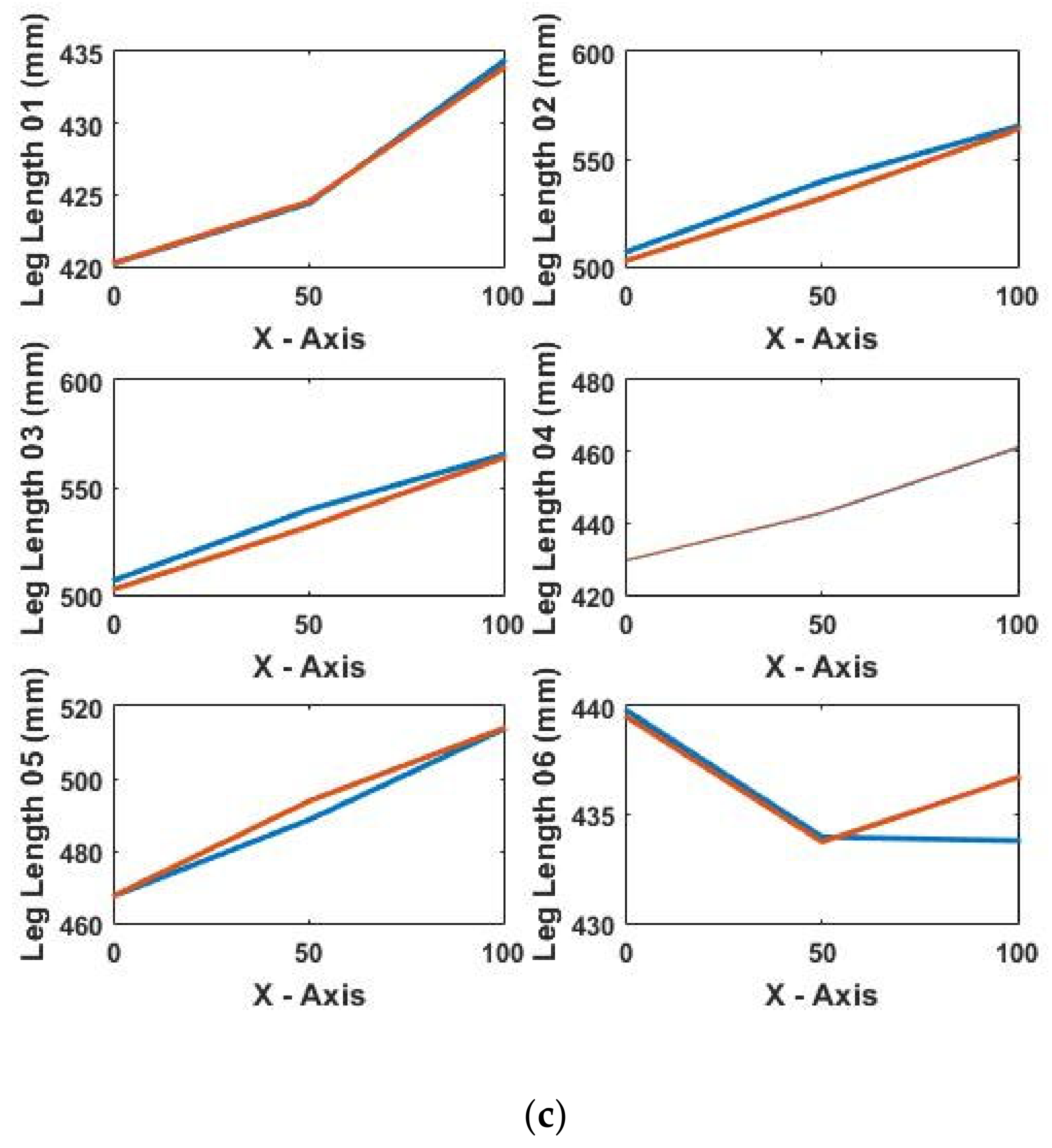
From Figure 17a–c it can be seen that there is some difference in the experimental and theoretical leg lengths obtained. There may be numerous reasons leading to this error. The error may be due to dislocation of the workpiece from the center of the moving platform of the bed (origin), clearance in the joints, and actuation errors of the linear actuators, to name a few. It is also noted that there was a measurement uncertainty up to 1% maximum that was contributing to the error. Figure 18 shows the errors in the actual and desired leg lengths for tests 01 to 03. It was observed that the maximum error was encountered when the machining bed was moving in the Z-axis. In Figure 18, leg 5 while moving from the X-axis to the Z-axis, produces more errors than the other legs, the reason being that for the workpiece under consideration, leg 5 had achieved maximum length and it encountered an error while tilting in the Z-axis.

6.3. Computational Time Algorithm Results

The computational time algorithm (CTA) was then applied to check for computational time reduction. Table 7 shows the comparison between the machining time with CTA and without CTA. It is evident that the machining time was reduced by 27%, hence reducing the energy consumed. In Table 7, the same leg lengths are shown in red.

7. Conclusions

A comprehensive study on the proposed machining bed was carried out in this research. The main contribution of this paper is to enhance the energy efficiency of the proposed machining bed. For this purpose, an energy efficiency model was presented. The significant findings in this research are:
  • The inverse kinematics model was presented and verified through different case studies and a workpiece.
  • The dynamics model for the machining bed was presented. Using this dynamics model, an energy efficiency model was presented. The energy efficiency model gives the efficiency of more than 50% which is a satisfactory result in case of a machining bed.
  • A PID controller was developed and implemented to reduce the errors in the workpiece trajectory through the leg lengths of the machining bed.
  • Another objective of this paper was to reduce the computational time for the workpiece trajectory on the machining bed so the machining time can be reduced. To achieve this objective an algorithm was developed. The results obtained show that the machining time was reduced by 27% approximately. The computational time is reduced to a reasonable percentage which eventually reduced the energy utilization and hence this model can be applied for commercial machining purposes. Future studies will consider better controller designs for better machining and reduction in energy consumption.

Author Contributions

All authors contributed equally to the literature review and fabrication of the proposed model. M.F.S., H.Y. and Z.K. proposed the research; M.T.S., O.R. and Z.M. developed the kinematics model; S.K., H.Z.U.R. and M.F.S. developed the dynamics model for the motor and machining bed; Z.K. and M.F.S. verified the kinematics model; H.Z.U.R., Z.K. and S.K. developed the controller for the system; M.F.S. and Z.K. developed the CTA. M.F.S., Z.K., Z.M., M.T.S. and O.R. contributed to analyzing the experimental data. All authors have read and agreed to the published version of the manuscript.

Funding

This research received no external funding.

Institutional Review Board Statement

Not Applicable.

Informed Consent Statement

Not Applicable.

Acknowledgments

Support from the Department of Mechanical Engineering, Khwaja Fareed University of Engineering and IT, Rahim Yar Khan, Pakistan is acknowledged.

Conflicts of Interest

The authors declare no conflict of interest.

Nomenclature

LiLeg Length of the ith leg of the proposed machining bed
TiTranslation Vector
XpDistance between the center and the attachment of ith leg at the movable top plate
XbDistance between the center and the attachment of ith leg at the fixed base plate
B P R Rotation Matrix
M1Mass of the fixed part of the linear actuator
M2Mass of the movable part of the linear actuator
ViAngular velocity of the moveable top plate
ImRotational inertia matrix of the movable top plate
E1Length of the fixed part of the linear actuator
E2Length of the movable part of the linear actuator
g1Center of mass for the fixed part of the linear actuator
g2Center of mass for the movable part of the linear actuator
KiTotal kinetic energy of the leg
VbBack emf
ωmAngular velocity of the DC motor attached to the linear actuator
TmThe torque of the DC motor attached to the linear actuator
JMass inertia of the DC motor attached to the linear actuator
DViscous damping of the DC motor attached to the linear actuator
ƟmAngular displacement of the DC motor attached to the linear actuator
EiEnergy consumed by the linear actuator
EmEnergy of the movable platform
EbTotal energy of the machining bed
PiPower consumed by the linear actuator
fiForce exerted by the linear actuator
viVelocity of the linear actuator

References

  1. Subagio, D.G.; Subekti, R.A.; Saputra, H.M.; Rajani, A.; Sanjaya, K.H. Three axis deviation analysis of CNC milling machine. J. Mechatron. Electr. Power Veh. Technol. 2019, 10, 93. [Google Scholar] [CrossRef]
  2. Lasemi, A.; Xue, D.; Gu, P. Recent development in CNC machining of freeform surfaces: A state-of-the-art review. CAD Comput. Aided Des. 2010, 42, 641–654. [Google Scholar] [CrossRef]
  3. Yamazaki, T. Development of A hybrid multi-tasking machine tool: Integration of additive manufacturing technology with CNC machining. Procedia CIRP 2016, 42, 81–86. [Google Scholar] [CrossRef]
  4. Stewart, D. A platform with six degrees of freedom. Proc. Inst. Mech. Eng. Part 1 1966, 180, 371. [Google Scholar] [CrossRef]
  5. Dasgupta, B.; Mruthyunjaya, T.S. Stewart platform manipulator: A review. Mech. Mach. Theory 2000, 35, 15–40. [Google Scholar] [CrossRef]
  6. Merlet, J.P. Force-Feedback control of parallel manipulators. In Proceedings of the IEEE International Conference on Robotics and Automation, Philadelphia, PA, USA, 24–29 April 1988; pp. 1484–1489. [Google Scholar]
  7. Wapler, M.; Urban, V.; Weisener, T.; Stallkamp, J.; Dürr, M.; Hiller, A. A Stewart platform for precision surgery. Trans. Inst. Meas. Control 2003, 25, 329–334. [Google Scholar] [CrossRef]
  8. Hu, B.; Zhang, L.; Yu, J. Kinematics and dynamics analysis of a novel serial-parallel dynamic simulator. J. Mech. Sci. Technol. 2016, 30, 5183–5195. [Google Scholar] [CrossRef]
  9. Uchiyama, M. Structures and characteristics of parallel manipulators. Adv. Robot. 1993, 8, 545–557. [Google Scholar] [CrossRef]
  10. Staicu, S. Dynamics of the 6-6 Stewart parallel manipulator. Robot. Comput. Integr. Manuf. 2011, 27, 212–220. [Google Scholar] [CrossRef]
  11. Shah, M.F.; Kausar, Z.; Farooq, S.S. Workspace design for 6 degree of freedom machining bed. J. Phys. Conf. Ser. 2018, 1016, 012018. [Google Scholar] [CrossRef]
  12. Huang, X.; Liao, Q.; Wei, S. Closed-Form forward kinematics for a symmetrical 6-6 Stewart platform using algebraic elimination. Mech. Mach. Theory 2010, 45, 327–334. [Google Scholar] [CrossRef]
  13. Liu, K.; Fitzgerald, J.M.; Lewis, F.L. Kinematic analysis of a Stewart platform manipulator. IEEE Trans. Ind. Electron. 1993, 40, 282–293. [Google Scholar] [CrossRef]
  14. Harib, K.; Srinivasan, K. Kinematic and dynamic analysis of Stewart platform-based machine tool structures. Robotica 2003, 21, 541–554. [Google Scholar] [CrossRef]
  15. Yang, G.; Chen, W.; Chen, I.M. A geometrical method for the singularity analysis of 3-RRR planar parallel robots with different actuation schemes. In Proceedings of the IEEE International Conference on Intelligent Robots and Systems, Lausanne, Switzerland, 30 September–4 October 2002; Volume 3, pp. 2055–2060. [Google Scholar]
  16. Shah, M.F.; Kausar, Z.; Farooq, M.U. Kinematic modeling and analysis of a 6 dof parallel machining bed. In Proceedings of the 22nd International Multitopic Conference INMIC 2019, Islamabad, Pakistan, 29–30 November 2019; IEEE: Piscataway, NJ, USA, 2019; pp. 1–5. [Google Scholar]
  17. Shah, M.F.; Kausar, Z.; Durrani, F.K. Design, modeling and simulation of six degree of freedom machining bed. Proc. Pak. Acad. Sci. 2016, 53, 163–176. [Google Scholar]
  18. Hao, K.; Ding, Y. Screw theory and singularity analysis of parallel robots. In Proceedings of the IEEE International Conference on Mechatronics and Automation ICMA 2006, Luoyang, China, 25–28 June 2006; Volume 2006, pp. 147–152. [Google Scholar]
  19. Boudreau, R. A real time solution to the forward kinematic problem of a general spherical three-degree-of-freedom parallel manipulator. Trans. Can. Soc. Mech. Eng. 1997, 21, 19–32. [Google Scholar] [CrossRef]
  20. Wang, L.-C.T.; Oen, K.-T. Numerical direct kinematic analysis of fully parallel linearly actuated platform type manipulators. J. Robot. Syst. 2002, 19, 391–400. [Google Scholar] [CrossRef]
  21. Lee, S.; Song, J.; Choi, W.; Hong, D. Position control of a Stewart platform using inverse dynamics control with approximate dynamics. Mechatronics 2003, 13, 605–619. [Google Scholar] [CrossRef]
  22. Glazunov, V.; Kheylo, S. Dynamics and control of planar, translational, and spherical parallel manipulators. In Dynamic Balancing of Mechanisms and Synthesizing of Parallel Robots; Springer: Cham, Switzerland, 2016; pp. 365–402. ISBN 9783319176833. [Google Scholar]
  23. Cheng, H.; Yiu, Y.K.; Li, Z. Dynamics and control of redundantly actuated parallel manipulators. IEEE ASME Trans. Mechatron. 2003, 8, 483–491. [Google Scholar] [CrossRef]
  24. Zhang, C.-D.; Song, S.-M. An efficient method for inverse dynamics of manipulators based on the virtual work principle. J. Robot. Syst. 1993, 10, 605–627. [Google Scholar] [CrossRef]
  25. Dasgupta, B.; Mruthyunjaya, T.S. Closed-Form dynamic equations of the general Stewart platform through the Newton-Euler approach. Mech. Mach. Theory 1998, 33, 993–1012. [Google Scholar] [CrossRef]
  26. Lebret, G.; Liu, K.; Lewis, F.L. Dynamic analysis and control of a stewart platform manipulator. J. Robot. Syst. 1993, 10, 629–655. [Google Scholar] [CrossRef]
  27. Zhang, Y.; Liao, Q.; Wei, S.; Wei, F.; Li, D. A novel geometric modeling and solution method for forward displacement analysis of 6-3 Stewart platforms. Mathematics 2021, 9. [Google Scholar] [CrossRef]
  28. Fichter, E.F. A Stewart platform-based manipulator: General theory and practical construction. Int. J. Robot. Res. 1986, 5, 157–182. [Google Scholar] [CrossRef]
  29. Luces, M.; Mills, J.K.; Benhabib, B. A review of redundant parallel kinematic mechanisms. J. Intell. Robot. Syst. Theory Appl. 2017, 86, 175–198. [Google Scholar] [CrossRef]
  30. Li, Y.; Bone, G. Are parallel manipulators more energy efficient? In Proceedings of the IEEE International Symposium on Computational Intelligence in Robotics and Automation, Banff, AB, Canada, 29 July–1 August 2001; IEEE: Piscataway, NJ, USA, 2001; pp. 41–46. [Google Scholar]
  31. Pasand, A.M.; Naderi, D. Energy optimization of a planar parallel manipulator with kinematically redundant degrees of freedom. In Proceedings of the RSI/ISM International Conference on Robotics and Mechatronics, Tehran, Iran, 13–15 February 2013; pp. 362–367. [Google Scholar]
  32. Kucuk, S. Energy minimization for 3-RRR fully planar parallel manipulator using particle swarm optimization. Mech. Mach. Theory 2013, 62, 129–149. [Google Scholar] [CrossRef]
  33. Saclera, L.; Boscario, P.; Carabin, G.; Vidoni, R.; Gasparetto, A. Enhancing energy efficiency of a 4-DOF parallel robot through task-related analysis. Machines 2020, 8, 10. [Google Scholar] [CrossRef] [Green Version]
  34. Pierrot, F.; Dauchez, P.; Fournier, A. HEXA: A fast six-DOF fully-parallel robot. In Proceedings of the Fifth International Conference on Advanced Robotics ‘Robots in Unstructured Environments, Pisa, Italy, 19–22 June 1991; Institute of Electrical and Electronics Engineers (IEEE): Piscataway, NJ, USA, 2002; Volume 2, pp. 1158–1163. [Google Scholar]
  35. Li, Y.; Staicu, S. Inverse dynamics of a 3-PRC parallel kinematic machine. Nonlinear Dyn. 2012, 67, 1031–1041. [Google Scholar] [CrossRef]
  36. Zhufeng, S.; Xiaoqiang, T.; Xu, C.; Liping, W. Inertia match of a 3-RRR reconfigurable planar parallel manipulator. Chin. J. Mech. Eng. 2009, 22, 791–799. [Google Scholar] [CrossRef]
  37. Patel, Y.D.; George, P.M. Simulation of kinematic and workspace analysis of 3-PRS parallel manipulator. Int. J. Model. Simul. Sci. Comput. 2015, 6, 1550007. [Google Scholar] [CrossRef]
  38. Zhang, Y.; Liao, Q.; Su, H.J.; Wei, S. A new closed-form solution to the forward displacement analysis of a 5-5 in-parallel platform. Mech. Mach. Theory 2012, 52, 47–58. [Google Scholar] [CrossRef]
  39. Gan, D.; Liao, Q.; Dai, J.S.; Wei, S. Design and kinematics analysis of a new 3CCC parallel mechanism. Robotica 2010, 28, 1065–1072. [Google Scholar] [CrossRef]
  40. Shah, M.F.; Kausar, Z.; Farooq, M.U.; Khan, L.A.; Farooq, S.S. Accuracy analysis of machining trajectory contemplating workpiece dislocation on a six degree of freedom machining bed. Proc. Inst. Mech. Eng. Part C J. Mech. Eng. Sci. 2020. [Google Scholar] [CrossRef]
  41. Shah, M.F.; Kausar, Z.; Ahmad, M.M. PID control and stability analysis of a six degree of freedom machining bed. Procedia Manuf. 2018, 17, 927–934. [Google Scholar] [CrossRef]
  42. Zhang, S.; Zhang, Y.H.; Zhang, X.N.; Dong, G.X. 1888. Fuzzy PID control of a two-link flexible manipulator. J. Vibroeng. 2016, 18, 250–266. [Google Scholar]
  43. Moradi, M.H. New techniques for PID controller design. In Proceedings of the IEEE Conference on Control Applications, Istanbul, Turkey, 25 June 2003; Volume 2, pp. 903–908. [Google Scholar] [CrossRef]
  44. Verma, B.; Padhy, P.K. Indirect IMC-PID controller design. IET Control Theory Appl. 2019, 13, 297–305. [Google Scholar] [CrossRef]
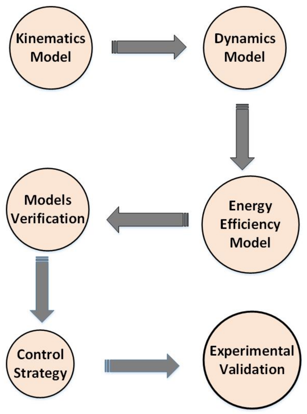
Figure 1. Block diagram representation of the proposed methodology.
Energies 14 02642 g001
Figure 2. SolidWorks(R) model of the proposed Machining Bed.
Energies 14 02642 g002
Figure 3. Schematic and vector representation of the proposed machining bed. (Right) schematic representation of kinematic chain connections and angle distribution. (Left) the schematic diagram for the ith leg of the mechanism.
Energies 14 02642 g003
Figure 4. Angle distribution on the movable top plate and fixed base plate.
Energies 14 02642 g004
Figure 5. Schematic representation of a linear actuator as a manipulator’s leg.
Energies 14 02642 g005
Figure 6. Representation of mechanical load in motor.
Energies 14 02642 g006
Figure 7. Relationship between angular and linear movement of linear actuator.
Energies 14 02642 g007
Figure 8. Flowchart for solving the inverse kinematics of the machining bed.
Energies 14 02642 g008
Figure 9. Schematic diagram of the workpiece selected for machining.
Energies 14 02642 g009
Figure 10. (a). Leg Length obtained for test 01 (Leg 2 and Leg 3 have same lengths); (b). Leg Length obtained for test 02 (Leg 2 and Leg 3 have same lengths); (c). Leg Length obtained for test 03 (Leg 2 and Leg 3 have same lengths).
Energies 14 02642 g010aEnergies 14 02642 g010b
Figure 11. Closed loop response of the machining bed to a step input.
Energies 14 02642 g011
Figure 12. Block diagram of the feedback control model for the machining bed.
Energies 14 02642 g012
Figure 13. The response of the machining bed system when PID controller is applied.
Energies 14 02642 g013
Figure 14. Fabricated model of the six DOF machining bed.
Energies 14 02642 g014
Figure 15. (a) Rotation in Z-Axis, (b) Translation in Z-Axis, (c) Rotation in Y-Axis, (d) Translation in Y- Axis, (e) Rotation in X-Axis, (f) Translation in X-Axis.
Energies 14 02642 g015
Figure 16. Experimental setup. (A pictorial view of the test being carried out by machining bed on a workpiece).
Energies 14 02642 g016
Figure 17. (a) Actual and desired leg lengths during test 01 for experimental validation; (b) Actual and desired leg lengths during test 02 for experimental validation; (c) Actual and desired leg lengths during test 03 for experimental validation.
Energies 14 02642 g017aEnergies 14 02642 g017b
Figure 18. Error in leg lengths of six legs (L1 to L6) for three different tests positions (C1, C2 and C3).
Energies 14 02642 g018
Table 1. Literature review of various configurations of six degrees of freedom parallel manipulators.
Sr. No.Proposed Configuration *Reference
13-PRC[36]
23-RRR[37]
33-PRS[38]
45-5-SPS[39]
53-CCC[40]
* P = Prismatic Joint, R = Revolute Joint, C = Cylindrical Joint, S = Spherical Joint.
Table 2. Tests results for verification of kinematics model.
TestCoordinates (mm)Leg NumberPredicted Length Computed from Kinematic Model (mm)
1[0;100;380]Leg 1397.38
Leg 2458.10
Leg 3458.10
Leg 4397.10
Leg 5404.37
Leg 6404.37
2[200;50;380]Leg 1416.66
Leg 2574.84
Leg 3574.84
Leg 4453.17
Leg 5503.78
Leg 6391.18
3[200;100;380]Leg 1426.6
Leg 2583.12
Leg 3583.12
Leg 4462.38
Leg 5500.68
Leg 6387.19
Table 3. Description of tests conducted on the workpiece.
Test NumberStart Coordinates (mm)End Coordinates (mm)Movement of Workpiece in Axis
1[50;0;380][125;0;380]X-Axis
2[125;0;380][125;0;430]Z-Axis
3[125;0;430][175;0;430]X-Axis
Table 4. Energy efficiency and calculations for linear actuator, moving platform and the machining bed.
Test NumberLeg Number E i ( mJ ) E m ( mJ ) E b ( mJ ) η (%)
1Leg 17.308.1215.753%
Leg 27.66
Leg 37.67
Leg 47.35
Leg 58.32
Leg 67.32
2Leg 15.337.813.160%
Leg 26.21
Leg 36.21
Leg 45.60
Leg 57.80
Leg 67.30
3Leg 16.457.714.752%
Leg 27.33
Leg 37.33
Leg 46.34
Leg 57.20
Leg 66.66
Table 5. Effect of PID gains on response parameters of the system [42].
Parameter *Rise TimeSettling TimeSteady State ErrorOvershoot
Kpδ
KiX
KdΔ
* ▼ = Decrease, ▲ = Increase, δ = Small change, X = Eliminate.
Table 6. Pseudocode for the algorithm (CTA) to reduce computational time.
Step No.Action
Step 1Initialize
Step 2Input coordinates and angles
Step 3Calculation of rotation matrix
Step 4If (Coordinates are in Y and Z axis only)
Step 5Compute leg length for leg 1, leg 2 and leg 5
Step 6If else (Coordinates are in X and Z axis)
Step 7Compute leg lengths for leg 1, leg 2, leg 4, leg 5, leg 6
Step 8Else
Step 9Calculate all leg lengths
Step 10End
Table 7. Comparison of machining time obtained with and without CTA.
Position Coordinates (mm)Leg NumberLeg Length (mm) *Machining Time (without CTA) (s)Machining Time (with CTA) (s)Reduction in Computation Time (s)
[50;0;380]L1380.250.760.550.21
L2469.8
L3469.8
L4390.55
L5431.99
L6401.78
[125;0;430]L1438.470.430.280.15
L2555.11
L3555.11
L4460.55
L5560.05
L6442.89
[175;0;430]L1450.880.480.310.17
L2587.96
L3587.96
L4480.7
L5537.47
L6445.6
* Leg Lengths in red have the same value.
Publisher’s Note: MDPI stays neutral with regard to jurisdictional claims in published maps and institutional affiliations.