Article

A Heater-Assisted Air Source Heat Pump Air Conditioner to Improve Thermal Comfort with Frost-Retarded Heating and Heat-Uninterrupted Defrosting

1
School of Energy and Power Engineering, Xi’an Jiaotong University, 28 Xianning West Road, Xi’an 710049, China
2
Qingdao Haier Air Conditioner General Corp., Ltd., Qingdao 266103, China
*
Author to whom correspondence should be addressed.
Energies 2021, 14(9), 2646; https://doi.org/10.3390/en14092646
Submission received: 5 April 2021 / Revised: 26 April 2021 / Accepted: 29 April 2021 / Published: 5 May 2021

Abstract

:
Frost deposits on the outdoor heat exchanger of an air source heat pump (ASHP) air conditioner and reduces its capacity during winter operation. However, the prevailing reverse-cycle defrosting (RCD) turns the indoor heat exchanger into an evaporator and ceases heat supply to the living space. Consequently, the thermal comfort for indoor occupants is deteriorated. This article proposes a heater-assisted ASHP to tackle this problem. With an 800 W electromagnetic heater equipped upstream of the outdoor heat exchanger to provide refrigerant with additional heat, the ASHP retarded frost under original throttling control and compressor speed during the heating cycle (frostless mode), and even removed frost with uninterrupted heat supply to indoor space under little throttling and reduced compressor speed (anti-frost mode). Compared with the original operation of the ASHP when the heater was off (baseline mode), frostless and anti-frost modes extended heating duration by 17.9% and 99.7%, respectively, with comparative time-averaged supply-air temperature. Moreover, COP for baseline and anti-frost modes was similar by average, about 3% higher than for the frostless mode. Further optimizations will be done on the co-adjustment of throttling control and compressor speed to better fulfill the potential of the heater-assisted ASHP.

Graphical Abstract

1. Introduction

One of the most challenging problems for the residential air source heat pump (ASHP) air conditioner is the phenomenon of frosting during winter operation. In this case, the ASHP capacity is degraded with reduced air flow rate and increased thermal resistance of the outdoor heat exchanger [1,2,3,4], thus necessitating timely defrosting. Currently, the prevailing method is reverse cycle defrosting (RCD). The ASHP is switched to the cooling mode, and hot refrigerant vapor is discharged to the outdoor heat exchanger to remove frost. During RCD cycles, however, the living space obtains no heat supply from the indoor heat exchanger since it serves as an evaporator. That is to say, both frosting and defrosting deteriorate the thermal comfort for occupants, which calls for improvements for the present form of an ASHP.
Many researchers have explored methods of retarding frost to enhance the thermal performance of the ASHP during heating cycles. Some used solid desiccant to reduce inlet air humidity and then the frost formation on the outdoor heat exchanger, so as to increase capacity and COP of the ASHP system [5,6]. Kwak and Bai [7] applied an electric heater in front of the outdoor unit of an ASHP to preheat the inlet air. The heating capacity increased by 38.0% and COP by 57.0% under the outdoor dry/wet bulb temperature of 2 °C/1 °C, which was attributed to the reduced frost formation. Lee et al. [8] investigated the effects of fin pitches, tube rows, and tube alignment on the heat transfer performance of fin-tube heat exchangers under frosting conditions, and found that fin pitch and staggered tube alignment had greater effects on the airflow reduction and thus affected frost retardation. Park et al. [9] studied frosting behaviors and thermal performance of the louvered-fin evaporator. Results showed that frost blocking between louvers was delayed and the thermal performance was improved by 21% with unequal louver-fin design. Okoroafor and Newborough [10] found that frost growth on cold surfaces was greatly reduced by means of cross-linked hydrophilic polymeric coatings. Frost thickness was decreased by 10–30% compared to using an uncoated metallic surface. Yang et al. [11] studied the frosting performance of a nanoporous hydrophilic aluminum surface in an ASHP, and found that nanoporous hydrophilic aluminum behaved better at lessening frost than polished aluminum, which revealed that manufacturing nanopores and promoting hydrophilicity can delay the formation of frost. Tang et al. [12,13] proposed a modified ASHP equipped with auxiliary electric heaters between the capillary and the evaporator, and introduced a comprehensive model to predict its performance. Results showed that the novel design effectively delayed frost formation and the model predicted COP and heating capacity of the ASHP with a deviation of 2.91% and 3.76%, respectively. Byun et al. [14] proposed a hot-gas bypass method to retard frost in a 1.12 kW capacity ASHP. The best performance was shown with a bypass refrigerant flow rate of 0.2 kg/min (20% of the whole refrigerant flow rate). During 210 min of heat pump operation, the hot gas bypass method improved COP and heating capacity by 8.5% and 5.7%, respectively, relative to the normal system. Mei et al. [15] proposed a frost-less heat pump to retard frost formation. By adding a moderate amount of heat to the refrigerant in the accumulator, the evaporator coil temperature was raised considerably. Therefore, the frost deposition was reduced and the frequency of defrosting cycles was decreased accordingly.
In addition, efforts were also made to improve the defrosting performance of the ASHP, mostly for RCD cycles. Song et al. [16] studied the effects of the accumulator on frosting/defrosting performance of an ASHP, and found that the removal of the accumulator produced 10% reduction in defrosting duration but 25% reduction in the integrated cyclic COP. Wang et al. [17] used a refrigerant charge compensator instead of an accumulator. Results showed that the defrosting performance improved with the increase in refrigerant flowrate and suction pressure. Niu et al. [18] used thermal energy storage (TES) and phase change material (PCM) in the ASHP system, and obtained better thermal comfort due to shorter defrosting duration and higher indoor supply-air temperature during RCD cycles. Song et al. [19] studied the effects of downward flowing of the melted frost over a vertical multi-circuit outdoor coil in an ASHP during RCD cycles. Results showed that with water-collecting trays to restrict the flow of melted frost, the duration of RCD cycles reduced and the defrosting efficiency increased by, at most, 13.2%. Other types of defrosting were also examined for the ASHP. Zheng et al. [20] proposed an ASHP combined with a refrigerant direct-condensation radiant floor heating system with composite PCMs, and found that the floor surface temperature, indoor air temperature, and heating capacity of the proposed system with composite PCMs were higher than those without composite PCMs in defrosting conditions. Liang et al. [21] adopted a self-organizing fuzzy control system in an ASHP unit to explore the sensible heat defrosting method. In this way, the four-way valve acted during the switching from heating to defrosting. The hot gas was discharged into the evaporator though the hot-gas solenoid valve, and melted frost with its sensible heat. However, a prolonged duration was shown in this new method. Liu et al. [22] designed the defrost system of an ASHP using compressor-case heat storage combined with the hot-gas bypass cycle. Results shows that the defrosting duration and energy consumption of this new method were 9% and 21.7% lower, respectively, than those for the RCD cycle. Moreover, the air temperature of the indoor heat exchanger outlet declined to only 3.3 °C and exerted less influence on the indoor temperature than the RCD cycle. Yin et al. [23] proposed a novel defrost method combining a tubular metal-sheathed heater and an air bypass channel in a food storage room. Results showed that the defrost duration decreased by 62.1%, while the defrost efficiency increased by 193% compared to the traditional electric heater defrosting method only. Tan et al. [24] introduced ultrasonic array defrosting into the ASHP system. Results showed that ultrasonic vibration assisted heat transfer efficiency and reduced the difference between ambient temperature and fin surface temperature. Moreover, it also assisted COP of the ASHP and suppressed frost deposition even if the frequency of power supply and ultrasonic vibration system were not well matched. Byrne et al. [25,26] studied the ASHP for simultaneous heating and cooling. Energy recovered by refrigerant subcooling was stored at first in a water tank and used subsequently as a cold source at the water evaporator to carry out defrosting of the air evaporator using a two-phase thermosiphon, so as to improve the overall performance.
From the aforementioned articles, it is concluded that though much work has been done on frosting and defrosting for ASHP systems, few of them have obtained uninterrupted heat supply to the indoor space during defrosting. Most existing defrosting methods demand shut-down or cycle switches of the ASHP system. Consequently, the living space obtains little heating and even gets cooling from the indoor heat exchanger during defrosting cycles. In addition, few of the methods above can be used for both frost retardation and defrosting improvement. That is to say, at least two of them should be combined to enhance both frosting and defrosting performance of the ASHP system, which will result in complicated system modifications.
Therefore, this study proposes an assisted ASHP system to improve thermal comfort for occupants with frost-retarded heating and heat-uninterrupted defrosting. An electromagnetic heater is equipped upstream of the outdoor heat exchanger to provide refrigerant with additional heat. Note that though heaters were used for the ASHPs in researches [7,12,15], there are three main differences between these researches and the present work, in terms of heater location, purpose, and effect. First, only Tang et al. [12] placed the heater upstream of the evaporator instead of downstream of it, while Kwak and Bai [7] and Mei et al. [15] place the heater in front of the HX and on the accumulator, respectively. By contrast, the present work installs the heater only upstream of the evaporator. Second, these researches [7,12,15] used heaters merely to retard frost during heating cycles for the ASHP unit, while the present work adopts the heater not only to retard frost during heating cycles but also to remove frost for defrost needs. Third, the researches [7,12,15] only achieved longer heating duration with the heater used, while the present work also obtains heat-uninterrupted defrosting. Therefore, both frosting and defrosting performance of the ASHP system is improved.

2. Experimental Apparatus and Procedures

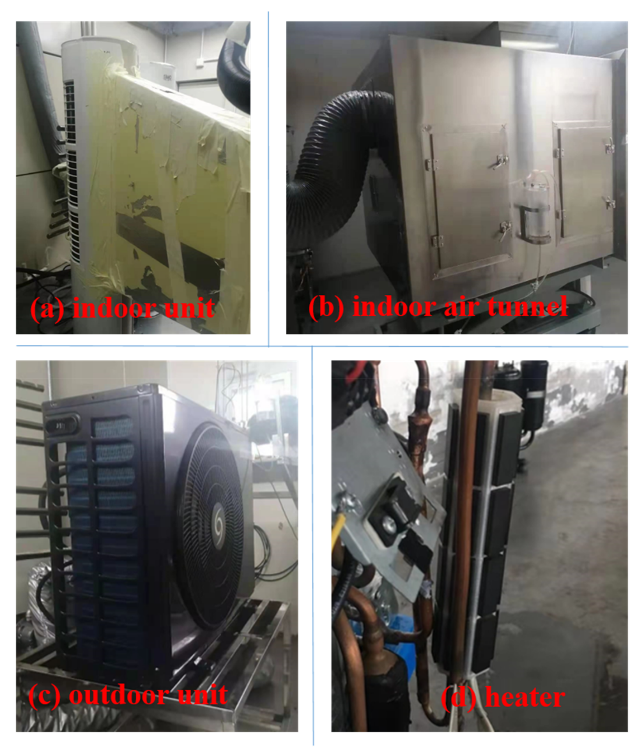
2.1. Experiment Apparatus

The experimental apparatus mainly consisted of three parts: the tested ASHP prototype, the standard calorimeter, and the data acquisition system.
Figure 1 schematically shows the tested ASHP prototype, which is fundamentally composed of a compressor, two finned-tube heat exchangers, and an electronic expansion valve (EEV). The compressor is a variable-frequency type Mitsubishi SV200 with the displacement of 47.5 cm3/rev. The outdoor heat exchanger has 60 tubes and the indoor coil 92 tubes, both spaced in two rows. The outer diameter of the tubes for both coils is 7 mm. The EEV is a Sanhua DPF (T01) 1.6C-45 model with full opening of 500 steps. The four-way valve enables the ASHP system to switch between heating and RCD modes. Refrigerant flows along the solid arrows in Figure 1 during heating cycles but the dashed arrows in RCD cycles, depending on the position of the four-way valve. The refrigerant is R32 with the charge of 1500 g.
To enhance thermal comfort performance of the ASHP prototype, an electromagnetic heater is added upstream of the outdoor heat exchanger to provide refrigerant with additional heat, as highlighted in Figure 1. With the synergic adjustment of the heater, the compressor, and the EEV, the refrigerant temperature in the outdoor heat exchanger is raised to an extent that can retard frost (higher than the original but below 0 °C) or even remove frost (above 0 °C), thus enhancing both frosting and defrosting performance of the ASHP.
Tests of the ASHP were conducted in a standard calorimeter with the indoor air enthalpy difference method according to Chinese Standard GB 21455-2013, as shown in Figure 2. The indoor and outdoor units of the ASHP system were placed in the indoor and outdoor rooms of the calorimeter, respectively. The dry/wet bulb temperature was set to 20/15 °C for the indoor room and 2/1 °C for the outdoor room. This condition is the most susceptible to frost of the three heating conditions designated in GB 21544-2013 for room air conditioners. Detailed information about the air enthalpy difference method and the standard calorimeter is referred to in the literature [27].
The data acquisition system collects and stores experiment data automatically during tests. Temperatures of the ASHP system and indoor supply air are captured by T-type thermocouples, which are calibrated in a standard thermal bath over the temperature range of −30 to 120 °C. The relative error of the thermocouples is ±0.2 °C. In addition, the power input of the system, which changes instantly at the initiation/termination of the ASHP, is monitored by a power meter with an error of ±0.4%. The capacity of the tested ASHP system is measured and read integrated with the air enthalpy difference method, and the relative error is ±1.0% according to the manufacturer of the calorimeter. COP is derived from the measured capacity and power input, whose uncertainty of ±1.1% was estimated following the single-sample methods proposed by Moffat [28]. The uncertainties of the measured and derived items are listed in Table 1.

2.2. Test Procedures

In this study, the ASHP was tested in three different modes, i.e., baseline, frostless, and anti-frost modes. The actions of the heater and other components in the three modes during the heating period are shown in Table 2.
In the baseline mode, the heater was OFF during the whole tests and the system was operated under cyclic heating and RCD cycles just as a normal ASHP unit. The compressor worked at constant speed of 90 Hz, and the EEV opening was controlled by the compressor discharge temperature with the target of 85 °C. The RCD cycle was initiated once the defrosting sensor on the outdoor coil dropped below −2 °C, and was terminated when defrosting sensor exceeded 10 °C for 20 s.
In the frostless mode, by contrast, the heater was always ON with 800 W power input during heating cycles under the same compressor speed, EEV control logic, and RCD scheme as the baseline mode. In this way, the surface temperature of the outdoor heat exchanger was elevated but still lower than 0 °C. Hence, frost deposition was retarded.
In the anti-frost mode, the heater was activated with 800 W power every 30 min in between heating cycles. The compressor speed and EEV control logic were the same within the baseline mode when the heater was OFF. However, the compressor was slowed down to 65 Hz and the EEV opening fixed at 480 steps once the heater was activated. In this way, refrigerant entering the outdoor coil was warmer than 0 °C and could remove frost as expected. During the electromagnetic-heater-defrosting (EHD) period, the ASHP called for no shut-down or reverse-cycle and the indoor unit still supplied heat to the living space, thus achieving uninterrupted heating under defrosting conditions. Note that this was a preliminary attempt and the 5 min EHD cycle was hardly enough to remove frost completely, so RCD was still triggered to protect the ASHP system with the same activation/termination scheme in the baseline mode.
Each of the three modes was tested for several steady cycles. The main performance data, such as capacity, power, and COP were the arithmetic average values generated from three repetitive experiments to obtain reliable and accurate experimental results, so as to improve the accuracy of the comparison.

3. Results and Discussion

Figure 3 illustrates four consecutive frosting/defrosting cycles for the baseline mode of the ASHP prototype. Each of these lasted for 70.2 min on average, of which the frosting cycle accounted for 65.1 min and the defrosting cycle, 5.1 min. All curves for the temperatures and the power input show good repetitiveness due to the consistent control logic. Moreover, the repetitiveness is also shown in frostless and anti-frost modes, which would not be repeated here. Then, the three operation modes of the ASHP were investigated comparatively, in terms of thermal comfort and energy performance.

3.1. Heating Duration

Thermal comfort performance of the ASHP is indicated first by heat-supply duration, since it is an overall reflection of both frost retardation and uninterrupted heating effect. Figure 4 comparatively illustrates the single frosting/defrosting cycle of the ASHP in all three modes. The heating supply lasted for 64.7 min, 76.3 min, and 128.8 min, respectively, in baseline, frostless, and anti-frost modes. The power input of the ASHP exhibits repeated oscillations at minimum points of the curve in the anti-frost mode, which is mainly attributed to the adjustment of compressor speed and EEV opening during the transition from EHD to heating cycles. Note that the heating duration in the anti-frost mode covered both the 30-min heating cycles and the 5-min EHD periods, since the indoor unit of the assisted ASHP still supplied warm air to the living space during the EHD process. To sum up, 17.9% longer heating duration was achieved in the frostless mode and 99.7% in the anti-frost mode. Longer heating duration means lower frequency of RCD actions during winter seasons, which would no doubt enhance thermal comfort for occupants.
For the frostless mode, longer heating duration was obtained due to frost retardation. Figure 5 shows frost on the outdoor heat exchanger at 40th min in both baseline and frostless modes. Obviously, frost coverage was thinner in the frostless mode than in the baseline one. The reason is that the 800 W electromagnetic heating increases the enthalpy of refrigerant into the evaporator, which increases its quality and pulls up the evaporation temperature. Figure 4 illustrates that the surface temperature of the evaporator is about 1.5 °C higher in the frostless mode than in the baseline mode. This complies with the work of Kim et al. [29], where it was seen that frost grows slower with higher surface temperature of the heat exchanger. Consequently, the heating cycle duration is prolonged with the identical RCD initiation signal. Longer heating duration is also obtained in the researches [7,12,15], where evaporation temperature was raised by adopting heaters upstream the inlet air, in tubes before and after the evaporator and on the accumulator.
For the anti-frost mode, by contrast, the extended heating duration was achieved by periodical removal of frost without ceasing heat supply to the indoor test section. With the compressor speed dropped by 25 Hz and the EEV almost fully open, the refrigerant entering the outdoor heat exchanger turned out to be warmer than 0 °C under the 800 W electromagnetic heating. Therefore, frost was removed to certain extent, as seen from the 0 °C evaporator temperature in the first three EHD cycles in Figure 4. The EHD actions recover part of the capacity loss of the ASHP during later heating operation. Moreover, it demands no shut-down or reverse-cycle of the ASHP, which means that warm air is still supplied to the indoor room of the calorimeter. Consequently, the heating duration is extended greatly from both aspects. In the work of Mei et al. [15], the heater on the accumulator provided heat for defrosting, which prevented the indoor space from being cooled down. However, heat supply to the living space was still ceased. The present study achieves uninterrupted heating even during EHD cycles, which would no doubt further promote the thermal comfort for the occupants.

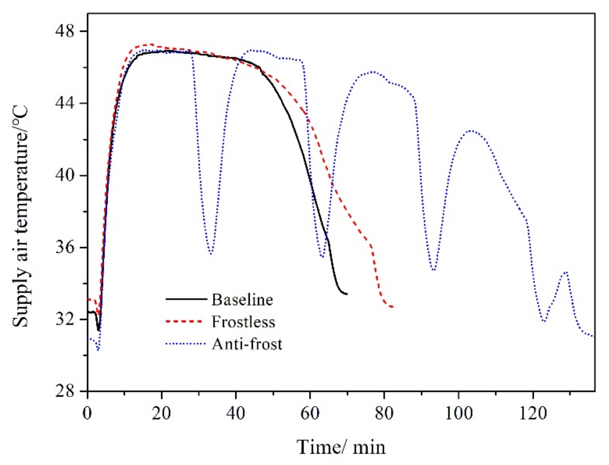
3.2. Supply-Air Temperature

Then, the supply-air temperature was compared among the three modes of the ASHP unit. Figure 6 shows the temperature curves for the supply air during frosting/defrosting cycles in baseline, frostless, and anti-frost modes, respectively. Generally speaking, the supply air was warmer in the frostless mode than in the baseline mode, and the reason is that the 800 W electromagnetic heating raises evaporator surface temperature with the increased refrigerant enthalpy, as shown in Figure 4. Besides, the supply-air temperature curves for baseline and anti-frost modes almost overlap with each other in the first 30 min due to the identical control logic. However, after the first 5 min EHD action, the supply air was obviously warmer in the anti-frost mode than in the other two modes, which indicates in turn that frost was partly removed on the outdoor coil and the hearting capacity was recovered to some extent.
Table 3 lists the time-averaged supply-air temperature during frosting/defrosting cycles of the ASHP. The supply-air temperature was 43.3 °C, 43.0 °C, and 41.3 °C by average, respectively, in baseline, frostless, and anti-frost modes. In general, the difference between the three average values was small, which means that all of the three modes exhibit comparative heating effect for occupants in the living space. The time-averaged supply-air temperature in the anti-frost mode was slightly lower than in the other two modes, which is mainly attributed to the cooler supply air during the EHD process when the compressor is slowed down and the EEV is almost fully open. However, even the supply-air temperature during EHD periods was about 36 °C, close to human body temperature of 36.3 °C and far higher than ambient temperature of 20 °C. That is to say, uninterrupted heating is realized in the anti-frost mode of the assisted ASHP system. Though the heater-assisted ASHP in this study hardly raises the average supply-air temperature, it reduces the frequency of RCDs, when the fluctuation is larger and may overweigh the advantage of the slight higher supply-air temperature, as indicated by Tang et al. [12].
The uninterrupted heat supply during EHD cycles was achieved in the anti-frost mode of the heater-assisted ASHP system, which shows the possibility of constant heating during the whole winter operation. In this study, however, the RCD action was still triggered after 2 h operation in the anti-frost mode, when the system supplies no heating to the living space. The reason is that a 5 min duration and 800 W heater power are hardly enough to remove frost completely, which is seen from Figure 4 which shows that the evaporator surface temperature never went higher than 0 °C during EHD cycles. Accordingly, the supply-air temperature also reduced in the later stage of the operation, as shown in Figure 6. In the future, the operation parameters will be optimized, covering heater power, EHD duration, compressor speed, and EEV opening in this mode, so as to fulfill the potential of constant heating of the ASHP.

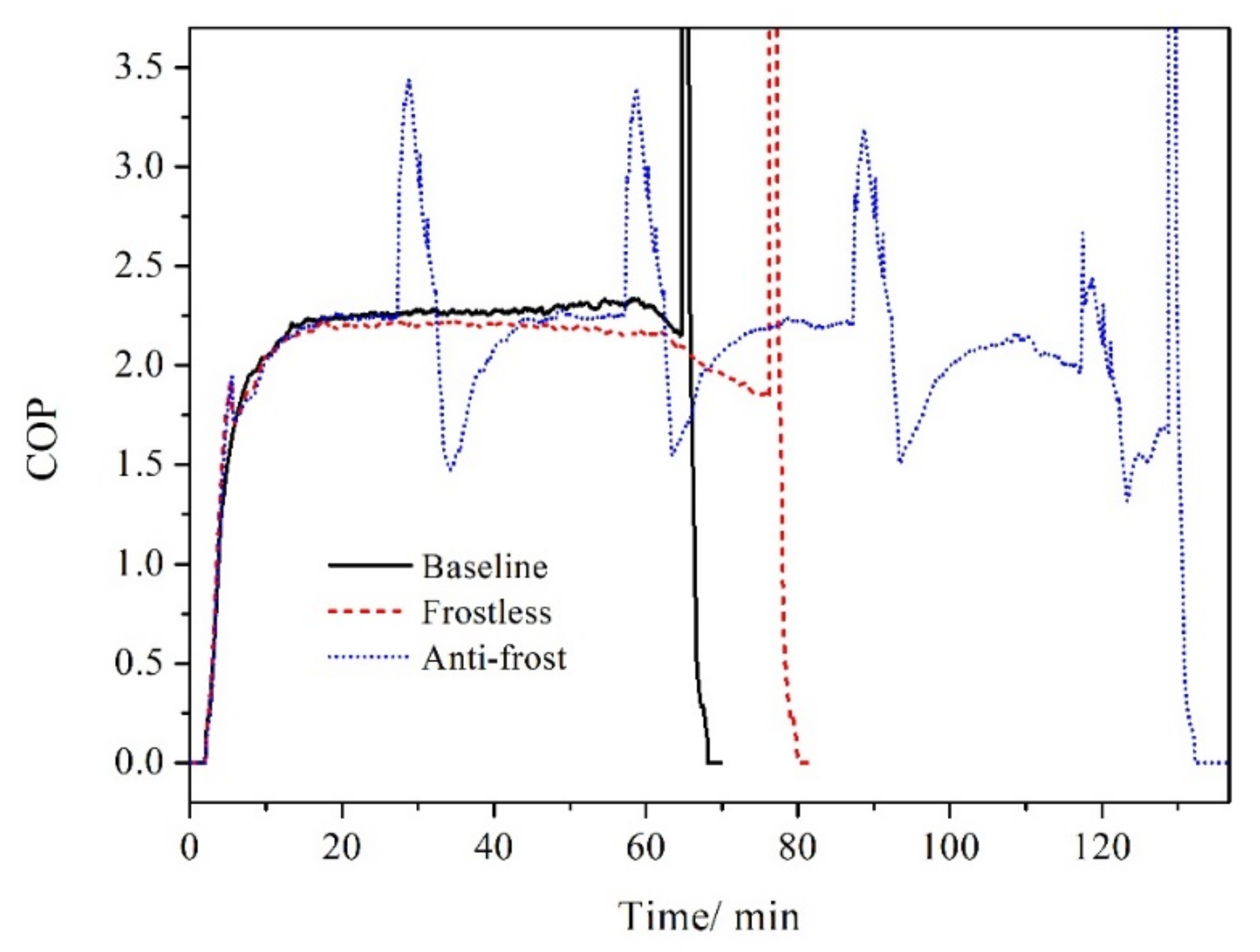
3.3. Energy Performance

The above results show that the heater-assisted ASHP extends heating duration with comparative time-averaged supply-air temperature in frostless and anti-frost modes, thus increasing thermal comfort for indoor occupants. In this section, we examine the energy effect of the additional heating on the ASHP unit.
Figure 7 and Figure 8 illustrate heating capacity and power input for the frosting/defrosting cycles, respectively, of the ASHP during the three modes. In general, both capacity and power in the frostless mode were slightly higher than in the baseline mode during the heating period with the 800 W additional electromagnetic heating. Besides, both of them were similar in baseline and anti-frost modes during the first 30 min due to the identical control logic, but started to be higher in the anti-frost modes than in the other two modes after the first EHD when part of the frost was removed. Note that the difference in capacity between baseline and frostless modes of this research is smaller than that of Mei et al. [15], which indicates again that there is still room for optimization of heater power, compressor speed, and EEV opening, so as to better fulfill the potential of performance enhancement for this heater-assisted ASHP.
Figure 9 comparatively presents COP of the heater-assisted ASHP for all the three modes. The curves share similar trends in baseline and frostless modes, i.e., rises at first, then keeps in the plateau, and finally drops before defrosting. In the anti-frost mode, by contrast, the COP curve undergoes several ups and downs in the whole heating duration, which is mainly attributed to the drop in both capacity and power during the EHD process (as seen in Figure 7 and Figure 8).
Table 3 comparatively lists the energy parameters during heating supply periods of the ASHP by average in all three modes. Seen from Table 4, the baseline mode exhibited the largest average capacity of 8780.8 W with the shortest descending period. By contrast, the anti-frost mode presented the smallest one of 8077.8 W because of the drop during the EHD process and the longest descending period. As for the power, the frostless mode had the largest average value of 4229.4 W, which was mainly due to the 800 W added heating. The anti-frost mode, however, also showed the smallest one due to the drop during the EHD process. Consequently, COP of the ASHP was similar in baseline and anti-frost modes, about 3% larger than that in the frostless mode.
To sum up, the anti-frost mode showed the longest heating duration, followed sequentially by the frostless and baseline modes. In addition, the time-averaged supply-air temperature was comparable among the three modes, with that in the anti-frost mode only slightly lower due to the periodic EHD actions. However, even the supply air in this period was no cooler than human body temperature, indicating that the heater-assisted ASHP succeeds in improving thermal comfort for occupants with longer heating duration and comparative supply-air temperature. Note that better thermal comfort is obtained at the price of reduced energy performance. The heater increases the power input with similar capacity of the ASHP by average, leading to reduced COP in the frostless mode. Moreover, the periodic EHD actions decrease both time-averaged capacity and power input, with similar COP for the baseline mode. However, there is still room for further improvement in terms of heater power, compressor speed, EEV opening, and other components, so as to better fulfill the potential of the heater-assisted ASHP system.

4. Conclusions

The frequent RCD actions turn the indoor heat exchanger into an evaporator and cease heat supply to the living space during winter operation of an ASHP air conditioner, thus reducing thermal comfort for occupants. In this article, a heater-assisted ASHP was proposed to address this problem. An 800 W electromagnetic heater was added upstream of the outdoor heat exchanger to provide refrigerant with additional heat. Three modes were tested experimentally for the ASHP system, i.e., the baseline mode with the heater always off, the frostless mode with the heater on during heating cycles, and the anti-frost mode with the heater on every 30 min in between heating cycles and lasting for 5 min. Meanwhile, the three modes shared the same control regime, except that the compressor speed reduces by 25 Hz and the EEV keeps almost fully open during the heater-on period in the anti-frost mode. The thermal comfort and energy performance are compared between the three modes. Detailed conclusions are as follows.
(1)
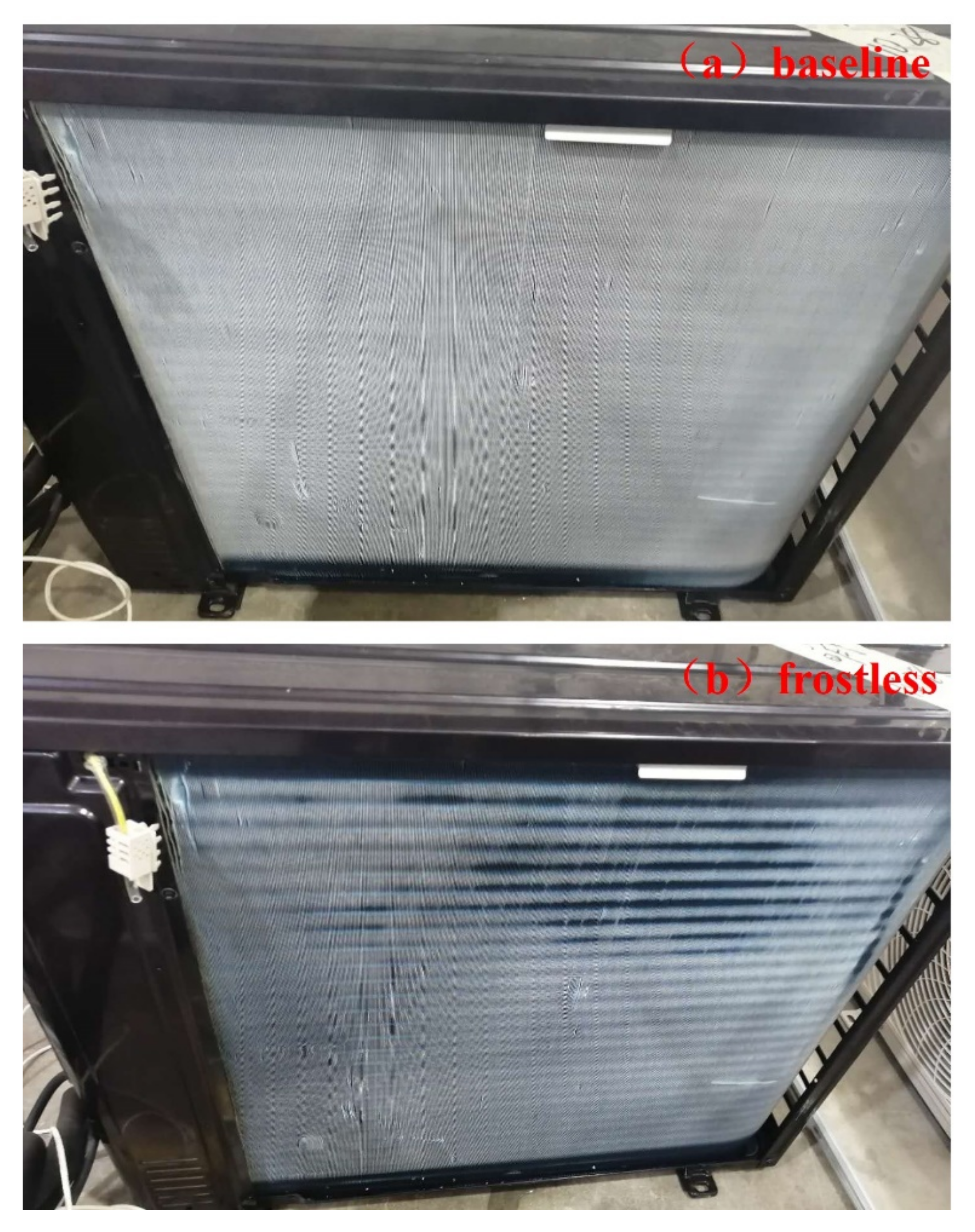
The 800 W heating elevates evaporator surface temperature by 1.5 °C, which contributes to retarding frost and extending heating cycle duration by 17.9% in the frostless mode.
(2)
The intermittent action of the heater removes part of the frost on the outdoor heat exchanger without ceasing heat supply to indoor spacing. Consequently, the heating duration is extended by 97.9% in the anti-frost mode.
(3)
Both frostless and anti-frost modes exhibit comparative supply-air temperature by average to the baseline mode. Moreover, even the supply-air temperature during the EHD process in the anti-frost modes are higher than 36 °C.
(4)
The anti-frost mode yields similar COP with the baseline mode, which is 3% larger than that in the frostless modes.
In short, the heater-assisted ASHP exhibits the longest heating duration in the anti-frost mode, followed by frostless and baseline modes sequentially. The time-averaged supply-air temperature is comparative in the three modes, of which that in the anti-frost mode is only slightly lower due to the periodic EHD actions. However, energetic price is paid to obtain the improvement in thermal comfort performance. The heater increases the power input with similar capacity of the ASHP by average, leading to reduced COP in the frostless mode. Meanwhile, the periodic EHD actions decrease time-averaged capacity of the ASHP for the baseline mode. In the future, the co-actions of system components will be further investigated, including heater power, EHD duration, compressor speed, and throttling, so as to better fulfill the overall performance of heater-assisted ASHP.

Author Contributions

F.W. and R.Z. implemented the main research; W.X. was involved in the experiment work; D.H. and Z.Q. provided guidance and supervision. All authors have read and agreed to the published version of the manuscript.

Funding

The present work is supported by the National Natural Science Foundation of China (No. 51806161) and Key Technology Research and Development Program of China (NO. 2019JZZY020813).

Institutional Review Board Statement

Not applicable.

Informed Consent Statement

Not applicable.

Data Availability Statement

Not applicable.

Conflicts of Interest

The authors declare no conflict of interest.

References

  1. Silva, D.; Hermes, C.; Melo, C. Experimental study of frost accumulation on fan-supplied tube-fin heat evaporators. Appl. Therm. Eng. 2011, 31, 1013–1020. [Google Scholar] [CrossRef] [Green Version]
  2. Kondepudi, S.N.; O’Neal, D.L. The effects of different fin configurations on the performance of finned-tube heat exchangers under frosting conditions. ASHRAE Trans. 1990, 96, 439–444. [Google Scholar]
  3. Kristian, L.; Anica, T.; Frankovic, B. Prediction of an effective cooling output of the fin-and-tube heat exchanger under frosting conditions. Appl. Therm. Eng. 2009, 29, 2534–2543. [Google Scholar]
  4. Zhao, R.; Qiao, L.; Gao, Z.; Huang, D. Effect of Vacuum Insulation Panels on Energy Consumption and Thermal Load Transfer between Compartments in a Three-Temperature Frost-Free Refrigerator. Energies 2020, 13, 1559. [Google Scholar] [CrossRef] [Green Version]
  5. Wang, F.; Wang, Z.; Zheng, Y.; Lin, Z. Performance investigation of a novel frost-free air-source heat pump water heater com-bined with energy storage and dehumidification. Appl. Energy 2015, 139, 212–219. [Google Scholar] [CrossRef]
  6. Giampieri, A.; Ma, Z.; Smallbone, A.; Roskilly, A.P. Thermodynamics and economics of liquid desiccants for heating, ventilation and air-conditioning—An overview. Appl. Energy 2018, 220, 455–479. [Google Scholar] [CrossRef] [Green Version]
  7. Kwak, K.; Bai, C. A study on the performance enhancement of heat pump using electric heater under the frosting condition: Heat pump under frosting condition. Appl. Therm. Eng. 2010, 30, 539–543. [Google Scholar] [CrossRef]
  8. Lee, M.; Kim, Y.; Lee, H. Air-side heat transfer characteristics of flat plate finned-tube heat exchangers with large fin pitches under frosting conditions. Int. J. Heat Mass Transf. 2010, 53, 2655–2661. [Google Scholar] [CrossRef]
  9. Park, J.-S.; Kim, D.R.; Lee, K.-S. Frosting behaviors and thermal performance of louvered fins with unequal louver pitch. Int. J. Heat Mass Transf. 2016, 95, 499–505. [Google Scholar] [CrossRef]
  10. Okoroafor, E.; Newborough, M. Minimizing frost growth on cold surfaces exposed to humid air by means of crosslinked hy-drophilic polymeric coatings. Appl. Therm. Eng. 2000, 20, 737–758. [Google Scholar] [CrossRef]
  11. Yang, W.; Zeng, B.; Zhang, Y.; He, S.; Zhao, X. Frosting Performance of a Nanoporous Hydrophilic Aluminum Surface. Energies 2018, 11, 3483. [Google Scholar] [CrossRef] [Green Version]
  12. Tang, J.; Gong, G.; Su, H.; Wu, F.; Herman, C. Performance evaluation of a novel method of frost prevention and retardation for air source heat pumps using the orthogonal experiment design method. Appl. Energy 2016, 169, 696–708. [Google Scholar] [CrossRef]
  13. Tang, J.; Hu, X.; Herman, C.; Gong, G. Computational modeling and prediction of the performance of air source heat pumps under frost prevention and retardation conditions. Energy Build. 2020, 224, 110264. [Google Scholar] [CrossRef]
  14. Byun, J.-S.; Lee, J.; Jeon, C.-D. Frost retardation of an air-source heat pump by the hot gas bypass method. Int. J. Refrig. 2008, 31, 328–334. [Google Scholar] [CrossRef]
  15. Mei, V.C.; Domitrovic, R.E.; Chen, F.C.; Kilpatrick, J. A frost-less heat pump. ASHRAE Trans. 2002, 108, 452–459. [Google Scholar]
  16. Song, M.; Deng, S.; Pan, D.; Mao, N. An experimental study on the effects of downwards flowing of melted frost over a ver-tical multi-circuit outdoor coil in an air source heat pump on defrosting performance during reverse cycle defrosting. Appl. Therm. Eng. 2014, 67, 258–265. [Google Scholar] [CrossRef]
  17. Wang, Z.; Wang, X.; Dong, Z. Defrost improvement by heat pump refrigerant charge compensating. Appl. Energy 2008, 85, 1050–1059. [Google Scholar]
  18. Niu, F.; Ni, L.; Yao, Y.; Yu, Y.; Li, H. Performance and thermal charging/discharging features of a PCM assisted HP system in heating mode. Appl. Therm. Eng. 2013, 58, 536–541. [Google Scholar] [CrossRef]
  19. Song, M.; Pan, D.; Li, N.; Deng, S.S. An experimental study on the negative effects of downwards flow of the melted frost over a multi-circuit outdoor coil in an air source heat pump during reverse cycle defrosting. Appl. Energy 2015, 138, 598–604. [Google Scholar] [CrossRef]
  20. Zheng, C.; You, S.; Zhang, H.; Liu, Z.; Zheng, W.; Wu, Z.; Fan, M. Defrosting performance improvement of air-source heat pump combined refrigerant di-rect-condensation radiant floor heating system with phase change material. Energies 2020, 13, 1459. [Google Scholar] [CrossRef]
  21. Liang, C.-H.; Zhang, X.-S.; Li, X.-W.; Chen, Z.-Q. Control strategy and experimental study on a novel defrosting method for air-source heat pump. Appl. Therm. Eng. 2010, 30, 892–899. [Google Scholar] [CrossRef]
  22. Liu, Z.; Fan, P.; Wang, Q.; Chi, Y.; Zhao, Z.; Chi, Y. Air source heat pump with water heater based on a bypass-cycle defrosting system using compressor casing thermal storage. Appl. Therm. Eng. 2018, 128, 1420–1429. [Google Scholar] [CrossRef]
  23. Yin, H.-J.; Yang, Z.; Chen, A.-Q.; Zhang, N. Experimental research on a novel cold storage defrost method based on air bypass circulation and electric heater. Energy 2012, 37, 623–631. [Google Scholar] [CrossRef]
  24. Tan, H.; Zhang, X.; Zhang, L.; Tao, T.; Xu, G. Ultrasonic Guided Wave Phased Array Focusing Technology and Its Application to Defrosting Performance Improvement of Air-Source Heat Pumps. Energies 2019, 12, 3117. [Google Scholar] [CrossRef] [Green Version]
  25. Byrne, P.; Miriel, J.; Lenat, Y. Experimental study of an air-source heat pump for simultaneous heating and cooling—Part 1: Basic concepts and performance verification. Appl. Energy 2011, 88, 1841–1847. [Google Scholar] [CrossRef] [Green Version]
  26. Byrne, P.; Miriel, J.; Lenat, Y. Experimental study of an air-source heat pump for simultaneous heating and cooling—Part 2: Dynamic behavior and two-phase thermosiphon defrosting technique. Appl. Energy 2011, 88, 3072–3078. [Google Scholar] [CrossRef] [Green Version]
  27. Song, X.; Huang, D.; Liu, X.; Chen, Q. Effect of non-uniform air velocity distribution on evaporator performance and its im-provement on a residential air conditioner. Appl. Therm. Eng. 2012, 40, 284–293. [Google Scholar] [CrossRef]
  28. Kim, J.-S.; Lee, K.-S.; Yook, S.-J. Frost behavior on a fin considering the heat conduction of heat exchanger fins. Int. J. Heat Mass Transf. 2009, 52, 2581–2588. [Google Scholar] [CrossRef]
  29. Moffat, R.J. Describing the uncertainties in experimental results. Exp. Therm. Fluid Sci. 1988, 1, 3–17. [Google Scholar] [CrossRef] [Green Version]
Figure 1. Schematic diagram of the tested ASHP prototype.
Energies 14 02646 g001
Figure 2. Pictures for the test apparatus: (a) indoor unit; (b) indoor air tunnel; (c) outdoor unit; (d) heater.
Energies 14 02646 g002
Figure 3. Four consecutive frosting/defrosting cycles in baseline mode.
Energies 14 02646 g003
Figure 4. Frosting/defrosting operations of the ASHP in the three modes.
Energies 14 02646 g004
Figure 5. Frost on evaporator surface at 40th min in (a) baseline and (b) frostless modes.
Energies 14 02646 g005
Figure 6. Supply-air temperature during frosting/defrosting cycles for the three modes.
Energies 14 02646 g006
Figure 7. Heating capacity of the ASHP for the three modes.
Energies 14 02646 g007
Figure 8. Power input of the ASHP for the three modes.
Energies 14 02646 g008
Figure 9. COP of the ASHP for the three modes.
Energies 14 02646 g009
Table 1. Uncertainties of measured and derived items in this research.
ItemAverage Supply-Air Temperature
Temperature±0.2 °C
Power±0.4%
Capacity±1.0%
COP±1.1%
Table 2. Co-actions of system components in the three modes during heating periods.
ModesHeater ActionCompressor SpeedEEV Opening
BaselineOFF90 Hz85 °C discharge control
FrostlessAlways ON90 Hz85 °C discharge control
Anti-frostON at 30-min intervals (for 5 min)65 Hz if heater on
90 Hz if heater off
480 steps if heater on;
85 °C discharge control if heater off
Table 3. Average values of supply-air temperature during frosting/defrosting cycles of the ASHP.
ModesAverage Supply-Air Temperature
Baseline43.3 °C
Frostless43.0 °C
Anti-frost41.3 °C
Table 4. Time-averaged energy outputs of the ASHP during heating supply for all modes.
ModesCapacity/WPower/WCOP
Baseline8780.84108.12.09
Frostless8761.04229.42.02
Anti-frost8077.83876.52.08
Publisher’s Note: MDPI stays neutral with regard to jurisdictional claims in published maps and institutional affiliations.

