Article

An Experimental Analysis of Water–Air Two-Phase Flow Pattern and Air Entrainment Rate in Self-Entrainment Venturi Nozzles

1
Department of Mechanical Engineering, Graduate School, Seoul National University of Science and Technology, Seoul 01811, Korea
2
Department of Mechanical and Automotive Engineering, Seoul National University of Science and Technology, Seoul 01811, Korea
*
Author to whom correspondence should be addressed.
Energies 2021, 14(9), 2664; https://doi.org/10.3390/en14092664
Submission received: 16 April 2021 / Revised: 2 May 2021 / Accepted: 3 May 2021 / Published: 6 May 2021

Abstract

:
For self-entrainment venturi nozzles, the effects of nozzle shapes and operating conditions on the water–air two-phase flow pattern, and the characteristics of the air entrainment rate have been investigated. A rectangular venturi nozzle with width and height dimensions of 3 mm and 0.5 mm was used with a vertically downward flow direction. The pressure ratio, which is the ratio of the inlet and outlet pressures, water flow rate, and diverging angle were set as experimental parameters. From the flow visualization, annular and bubbly flows were observed. In the case of bubbly flow, the more bubbles that are generated with a higher water flow rate, the smaller the pressure ratio. In the case of annular flow, the increased pressure ratio and water flow rate induce the breakup of air core in the diverging area and make the interfacial oscillation stronger, which finally causes the flow transition from annular to bubbly flow, by accompanying a sharp increase in the air entrainment rate. During this flow transition, the frictional pressure drop of the two-phase flow is reduced, showing that a two-phase multiplier gets smaller.

1. Introduction

A venturi nozzle has various flow characteristics according to flow velocity and pressure as the working fluid passes through the channel. In particular, several studies have been reported in diverse fields of research, such as water quality improvement [1,2], bioreactors [3], and dust-laden gases [4], regarding the characteristics of two-phase flows that occur when an immiscible mixture of liquids and gases is injected together. The venturi nozzle is also one of the most well-known devices for generating micro-bubbles when the working fluid is water and air. As such, there has been active, ongoing research into the effect of nozzle shape and flow conditions on the quantity and size of micro-bubbles [5,6,7,8].
A self-entrainment venturi nozzle has the same operating principle as a regular venturi nozzle but is also equipped with an air hole. The negative pressure formed when the fluid passes through the narrow throat enables the self-entrainment of ambient air into the channel. It has the advantage of being able to entrain the air automatically, without the supply of additional power. In addition, this type of venturi nozzle has a relatively simple structure and a higher efficiency than other devices for micro-bubbles, which have been widely used as water purification devices [1,9]. However, it is difficult to control the discharge characteristics and flow rate because the amount of air entrainment is indirectly determined by the negative pressure formed inside the nozzle. It should also be noted that unlike single-phase flow, two-phase flow has a different pressure drop depending on the flow pattern, even if the geometry of the venturi nozzle is the same.
Prior studies [10,11] on self-entrainment venturi nozzles identified the characteristics of the air entrainment rate as well as various design variables, including the diverging and converging angles, the total length of the nozzle, and the size and location of an air hole. In addition, Guerra et al. [12] and Baylar et al. [13] numerically investigated the flow distribution within the channel, as well as the air entrainment rate. Lee et al. [9] found that the air entrainment rate peaked at a diverging angle of 60° and smaller micro-bubbles were generated at a larger diverging angle due to flow separation.
Previous research has also analyzed the pressure drop for two-phase flow through diverging channels in a venturi nozzle. Roul and Dash [14] performed a numerical analysis of the two-phase flow through a sudden diverging channel to investigate pressure and velocity distributions and presented a new correlation for the two-phase frictional pressure drop. Huang et al. [15] investigated the pressure drop formed when an ethanol-carbon dioxide gas two-phase flow passes through the diverging channel. Lee and Pan [16] experimented on slug bubbles flowing through the horizontal and diverging channels to figure out the effect of the channel shape on the pressure drop.
The above studies on the self-entrainment venturi nozzle have been mostly related to micro-bubble generation and as a result, the experimental conditions have been limited to bubbly flow. However, a wide spectrum of research is needed because numerous types of two-phase flow patterns can be formed inside a self-entrainment venturi nozzle, depending on the driving conditions and geometries.
In this study, experiments on self-entrainment venturi nozzles driven under various conditions are conducted. The effect of pressure, as well as the water flow rate and diverging angle on the self-entrainment venturi nozzle are further investigated. The water–air two-phase flow pattern is visualized by a high-speed CCD camera. The characteristics of the air entrainment rate are analyzed by the measurement of the pressure ratio of inlet and outlet and pressure. In addition, the changes of flow pattern and frictional pressure drop are discussed according to the water flow rate, diverging angle, and pressure ratio.

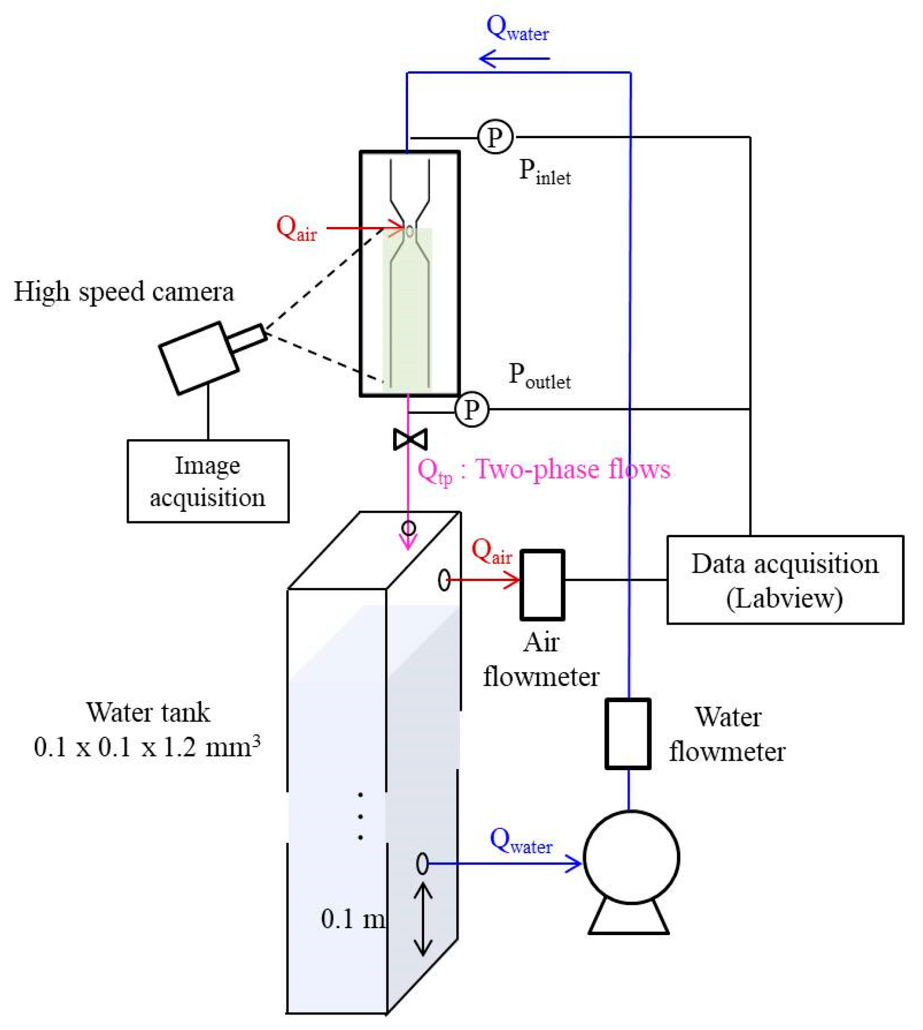
2. Experimental Method

The schematic of the self-entrainment venturi nozzle is shown in Figure 1. The nozzle has a rectangular cross-section with a width (d) and height (h) of 3 mm and 0.5 mm, respectively, and a throat width (dth) of 1 mm. An air hole with a diameter (dair) of 0.5 mm is formed on the throat section where the negative pressure occurs when water passes through the venturi nozzle. A total of seven specimens with the diverging angle (α) ranging from 20° to 80° were fabricated. The converging angle (θ) was fixed to 20°.
The nozzles are made of transparent acrylic to visualize water–air two-phase flows caused by air entrainment. The images are collected using a CCD camera (VEOE-310L) at 1000 frames per second, and to capture the frozen images of bubbles, the exposure time of the CCD camera is reduced to 2 μs by controlling the shutter speed. Figure 2 shows the experimental setup and data acquisition devices for the self-entrainment venturi nozzle. The venturi nozzle is installed beyond the top of a water tank, so that the water–air two-phase flow is vertical downward. At the top of the tank, an empty space is formed to separate the air from the two-phase flow. An air flowmeter (NEW-FLOW) is installed to measure the air flow rate (Qair). The water flow rate (Qwater), which is controlled by a pump and a flow meter (OF10ZAT), varies from 400 to 700 mL/min. The inlet and outlet pressures of the venturi nozzle are measured using a pressure sensor (Keyence, AP-43, AP-44) and a shut-off valve is installed at the rear of the outlet to control the driving pressure.
The pressure ratio at the inlet and outlet (Pr = Poutlet/Pinlet) is set during the experiments. When the opening ratio of the shut-off valve varies, the pressure ratio changes, which affects the water flow rate depending on the diverging angle. In all cases, experiments are performed from the smallest controllable pressure ratio of 0.02, to the maximum pressure ratio (Pr_max) where air is not entrained. Table 1 shows the maximum pressure ratio according to the water flow rate and the diverging angle. Prior to every data collection, stabilization to reach a steady state is performed for a minute. The data signals of air flow rate and inlet and outlet pressures are synchronized by the Labview program and a total of 5000 data are collected at a 1 kHz sampling rate.
A detailed description of the measuring devices is summarized in Table 2. In the two-phase flow, the Reynolds numbers (Re) for each water and air flow are separately calculated. The results show that the water flow is turbulent, and the air flow is laminar (Rew > 2000, Rea < 2000). The Reynolds number for each phase is defined as follows:
Re w = ρ w v w D h μ w                     Re a = ρ a v a D h μ a    
D h = 2 h d h + d    
where the subtopics ‘w’ and ‘a’ indicated phase of water, and air and ρ, μ, v, and Dh are the density, viscosity, velocity, and hydraulic diameter, respectively.

3. Results and Discussion

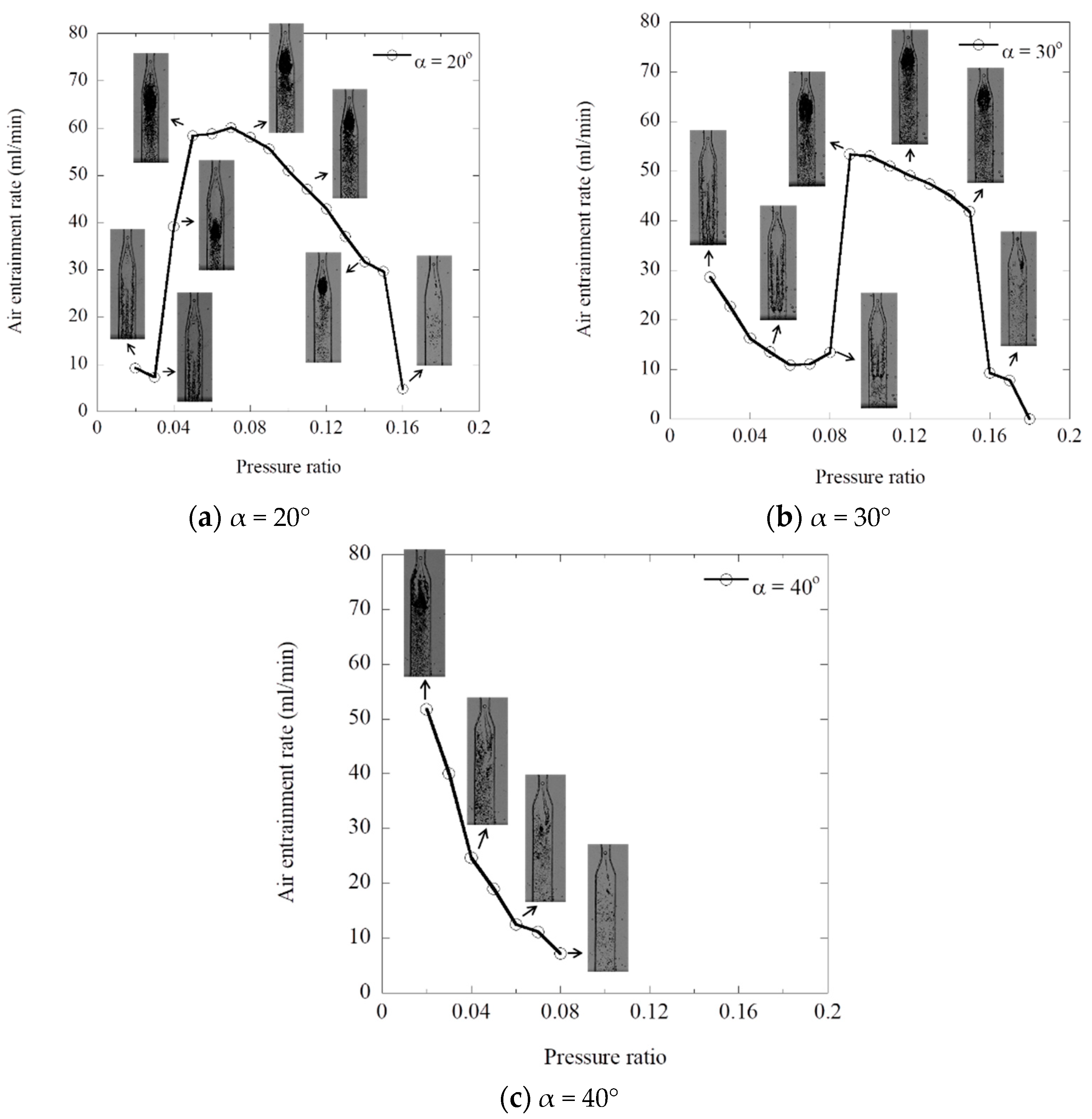
3.1. Visualization of Water–Air Two-Phase Flows

The water–air two-phase flows under various experimental conditions, such as diverging angle, water flow rate, and pressure ratio, are analyzed based on flow visualization. For self-entrainment venturi nozzles, previous studies [9,13] showed that slug or bubbly flow is the primary flow pattern observed when the outlet pressure is set to be the atmospheric pressure. The hydraulic diameter in the previous studies was several centimeters wide, and the water flow rate was 1000 mL/min or more. However, in this study, smaller nozzles with a hydraulic diameter of less than 1 mm are used, and the outlet pressure is also changed.
Figure 3 shows the visualized images of the water–air two-phase flow according to the water flow rate and diverging angle when the pressure ratio is 0.02. The two-phase flow patterns inside the self-entrainment venturi nozzle are formed as annular and bubbly flows. Note that the annular flow is not observed in the previous studies [9,13]. In the present study, the water velocity at the throat is up to 23.3 m/s, which is much faster than that of previous studies [9,13]. Thus, there happens to be higher negative pressure in the venturi throat and more air is entrained, which likely results in annular flow. As shown in Figure 3, air is entrained as a continuous phase through the air hole. Then, the water–air two-phase flow is formed as annular or bubbly flow after the flow passes through the venturi throat. The annular flow consists of a continuous air core in the central channel and a water film on the channel wall. As the water flow rate increases, the air core region gradually expands to downstream and the interfacial oscillation between the air and water phase becomes strong. The oscillation is an important phenomenon, which leads to an increase in the frictional pressure drop in the annular flow and entrains the water into the gas core in the form of droplets [17]. The interfacial oscillation causes a break-up and collapse of the core-shaped air phase, so that bubbles are generated near the air core. The diverging angle affects the interfacial oscillation, as shown in Figure 3b,c. Comparing the results according to the diverging angles, the air core in the gradual diverging nozzle is extended along the diverging wall and stable annular flows are formed. However, in the case of the sudden diverging nozzle, flow separation and eddies are observed in the diverging area. This results in a strong interfacial oscillation, and hence, many bubbles are generated around the interface of the air phase. In the bubbly flow, as shown in Figure 3d–f, the continuous air phase is dispersed and breaks into bubbles. If the pressure ratio is a constant, the amount of bubbles increases as the water flow rate increases and more bubbles are found in the sudden diverging nozzle due to the strong interfacial oscillation.
The two-phase flow behavior, according to the pressure ratio, is compared at the water flow rate of 700 mL/min in Figure 4 and Figure 5. The bubbly flows in Figure 4 occur at the diverging angle of 40° and 80°, and annular flows in Figure 5 occur at the diverging angle of 20°, 30°, 50°, 60° and 70°. In the case of bubbly flow, the number of bubbles gradually decreases as the pressure ratio increases, regardless of the diverging angle. Likewise, in the case of annular flows, the increase in pressure ratio results in the decrease in the air core. However, it is interesting to observe that as the pressure ratio increases, the flow transition from annular to bubbly flow is found as shown in Figure 5a. At the lowest pressure ratio value of 0.02, the air core gradually decreases with the increase in pressure ratio. At the pressure ratio of 0.04, a transitional flow with both annular and bubbly flows is observed. When the pressure ratio reaches 0.05, the flow transition is completed and only bubbly flow is observed. After that, the number of bubbles decreases with the increase in pressure ratio, which is the same phenomenon observed in the bubbly flow of Figure 4. For the other diverging angles, as shown in Figure 5b–e, the flow transition from annular to bubbly flow also occurs. However, the value of pressure ratio where the transition occurs is different.

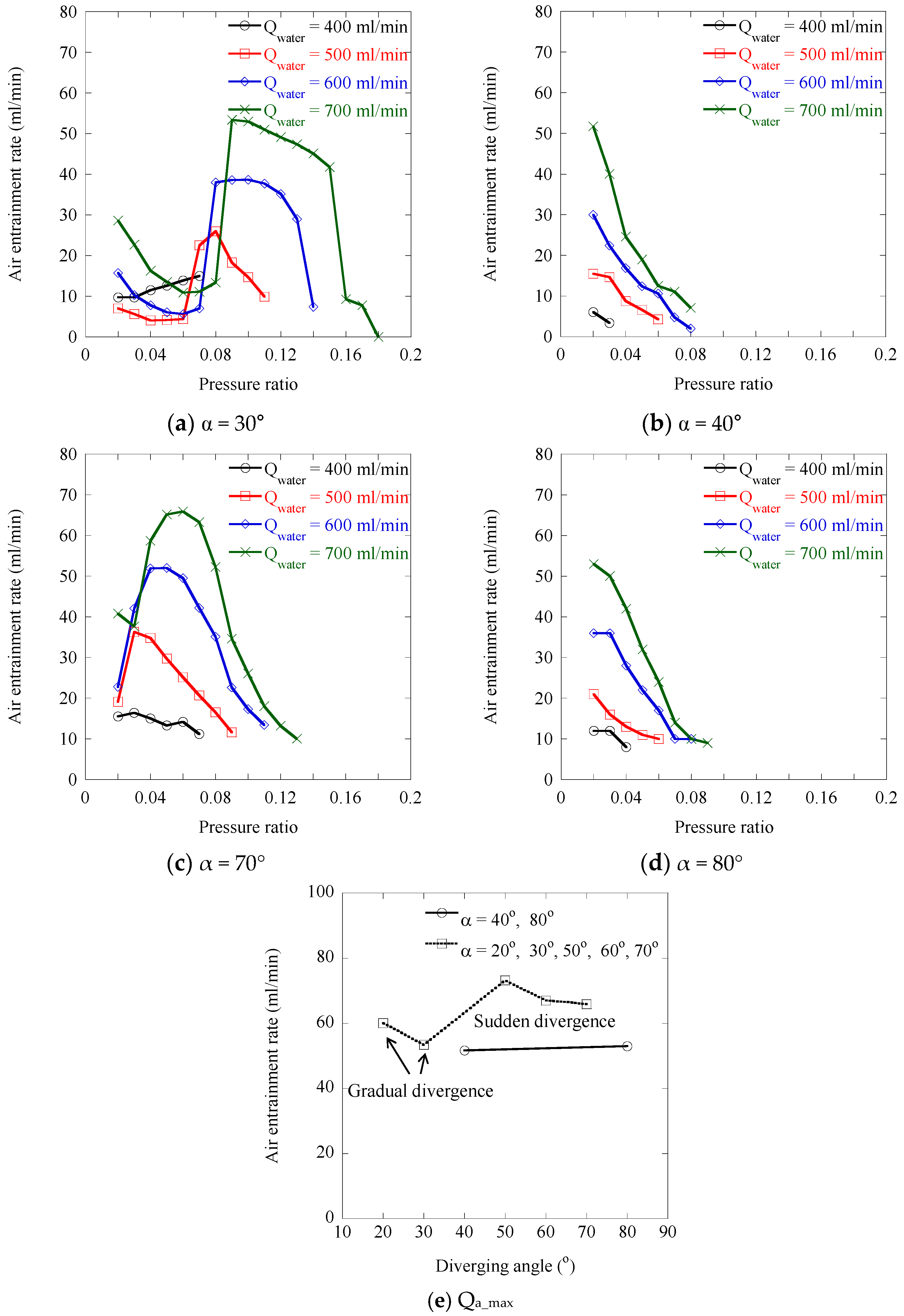
3.2. Effect of the Two-Phase Flow Pattern on Air Entrainment Characteristics

Figure 6 shows the relationship between the air entrainment rate and the pressure ratio for various diverging angles and water flow rates. At a given diverging angle, more air is entrained with the increased water flow rate, but it depends on the pressure ratio. As shown in the figure, the air entrainment rate decreases with an increase in pressure ratio for diverging angles of 40° and 80°. However, for the other diverging angles, the air entrainment rate has a peak value at a specific pressure ratio. For the diverging angles of 30°, the air entrainment rate decreases first and then increases as the pressure ratio increases, whereas for the diverging angles of 70°, the air entrainment rate starts to increase, even at a low pressure ratio. In Figure 6e, the maximum air entrainment rates (Qa_max) are compared according to the diverging angle. The maximum air entrainment rate has a similar value at both the diverging angles of 40° and 80°. However, for the other diverging angles, it is larger in the sudden diverging nozzles than in the gradual diverging nozzles. The largest air entrainment rate is observed at the diverging angle of 50°.
In order to investigate the effect of the water–air two-phase flow pattern on air entrainment characteristics, the visualized images of annular and bubbly flows are compared with the air entrainment rate in Figure 7. As shown in Figure 7a,b, for the low pressure ratio, annular flows are observed. In the status of annular flow, the air entrainment rate decreases with the increase in pressure ratio. If the pressure ratio further increases, the transition of flow pattern from annular to bubbly flow occurs accompanying a sharp increase in the air entrainment rate. When the air entrainment rate reaches a peak value, bubbly flow becomes dominant. However, in the case of the diverging angle of 40° in Figure 7c, no annular flow is found, even at a low pressure ratio. As long as the bubbly flow is maintained, the air entrainment rate decreases with the increase in pressure ratio. The pressure ratio of the peak air entrainment rate varies with the diverging angle.
In summary, the increase in pressure ratio reduces the negative pressure formed in a venturi nozzle’s throat and causes a decrease in the air entrainment rate if there is no change in flow pattern. However, during the transition from annular to bubbly flow, the nozzle experiences a sharp increase in the air entrainment rate. Thus, to achieve a maximum air entrainment through an air hole, it is most effective to apply the pressure ratio at the end of flow transition.

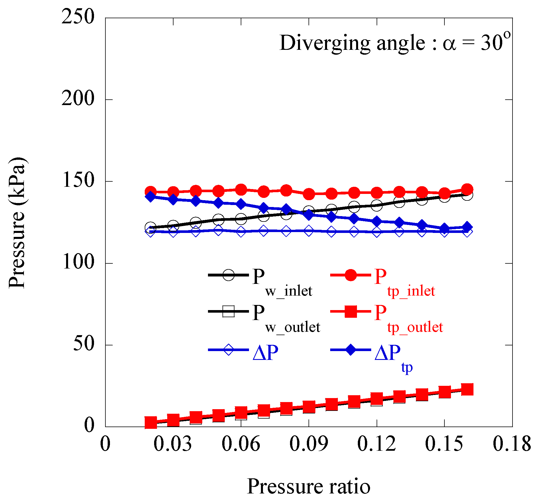
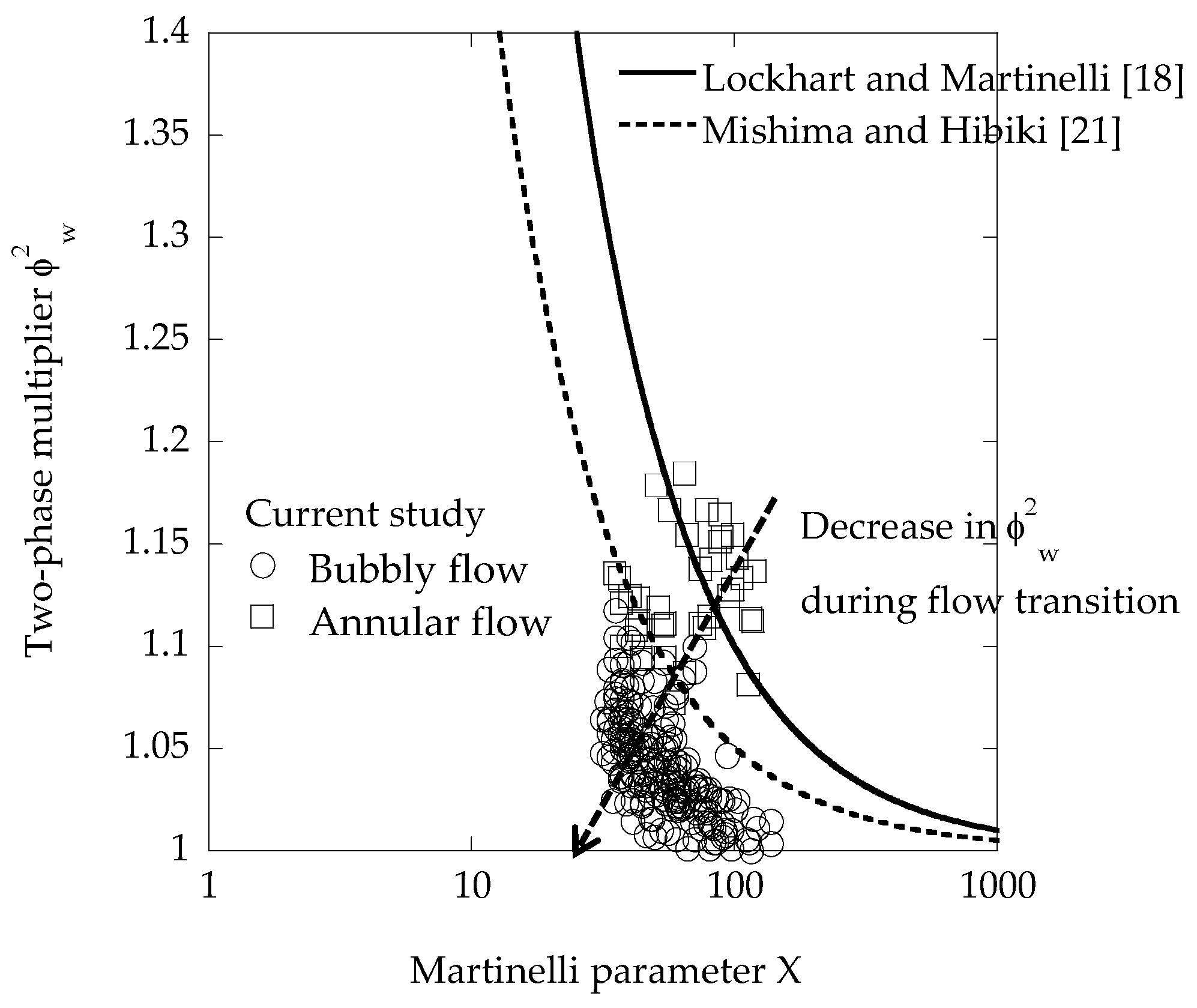
3.3. Pressure Drops According to the Two-Phase Flow Pattern

In order to analyze the pressure drop caused by water–air two-phase flow within the self-entrainment venturi nozzle, the variations of inlet and outlet pressures are plotted in Figure 8 at various pressure ratios. Here, the water flow rate is the same at 700 mL/min. Experiments are conducted for both the water-only single-phase flow (Pw) and water–air two-phase flow (Ptp). The pressures in the water-only single-phase and water–air two-phase flows are measured in the nozzles without and with an air hole, respectively. It is interesting to find out that as the pressure ratio increases, the inlet pressure increases in the single-phase flow, while it remains nearly constant in the two-phase flow. Since the flow rate is constant, the pressure drop in the single-phase flow (△Pw) always remains constant, which results in the increase in outlet pressure by the increased pressure ratio. On the other hand, the pressure drop in the two-phase flow (△Ptp) decreases as the pressure ratio increases. Thus, the difference in pressure drop between the single-phase and two-phase flows becomes smaller at the larger pressure ratio. If the pressure ratio increases up to a critical value, no air is entrained through the air hole and water-only single-phase flow is found even in the existence of an air hole. In this status, there is no difference in both the pressure drops in the single-phase and two-phase flows.
Based on the above results, the pressure drop (∆P) in the self-entrainment venturi nozzle is analyzed. The pressure drop of the water–air two-phase flow passing through the diverging area is expressed in the following equation:
( d p d z ) t p = ( d p d z ) f r i c t i o n + ( d p d z ) a c c e l e r a t i o n + ( d p d z ) expansion
The right side of the equation represents the various factors for the pressure drop. They consist of friction, acceleration, and expansion terms of the pressure drop in the diverging channel. An examination of previous studies [15,16] shows that the pressure drop due to friction at the water–air interface is the primary contributing factor. Several relevant models on frictional pressure have been proposed. A correlation scheme [18], which was the most commonly used for the two-phase frictional pressure drops, is to adopt a two-phase multiplier (ϕw) and a Martinelli parameter (X). The respective definitions are as follows:
( d p f d z ) t p = ϕ w 2 ( d p f d z ) w
X 2 = ( d p f d z ) w / ( d p f d z ) a
Here, (dpf/dz)tp represents the frictional pressure drop in the water–air two-phase flow. (dpf/dz)w and (dpf/dz)a represent the single-phase frictional pressure drop when only water or air is flowing in the channel. The two-phase multiplier (ϕw) denotes the multiplication factor of pressure drop by the two-phase flow, with respect to single water-phase flow. For the same water flow rate, the pressure drop in the two-phase flow is always larger than that in the water-phase flow, thus ϕw is larger than 1. The Martinelli parameter is the ratio of the frictional pressure drops between water and air phases. If the air and water flow conditions are laminar and turbulent, respectively, it is formulated based on friction laws as follows:
X = 0.054 Re w 0.4 ( μ w μ a ) 0.5 ( 1 x x ) 0.5 ( ρ a ρ w ) 0.5
where the parameter x refers to the vapor quality and is calculated as follows if the mass flow rate of water m ˙ w and the mass flow rate of entrained air m ˙ a are given.
x = m ˙ a m ˙ w + m ˙ a
Muzychka and Awad [19] mentioned that the interfacial characteristics affect the frictional pressure drops strongly in the region of 0.01 < X < 100, and hence, the two-phase multiplier is dependent on a two-phase flow pattern.
Chisholm [20] proposed the following correlation between the two-phase multiplier and Martinelli parameter by using Chisholm parameter (C):
ϕ w 2 = 1 + C X + 1 X 2
where the parameter C is set to be 10, regardless of the channel shape or size, if the water and air are turbulent and laminar, respectively. For a micro and mini channel, Mishima and Hibiki [21] modified the parameter C, using hydraulic diameter Dh (millimeter unit) as follows:
C = 21 ( 1 e 0.319 D h )
In this study, the cross-sectional area of the venturi nozzle is not constant so that an average of the hydraulic diameter [15], Dh_a, is calculated as follows for the length of the tube, l:
D h _ a = 2 h l 0 l w ( z ) h + w ( z ) d z
Figure 9 shows the relationship between the two-phase multiplier and the Martinelli parameter for all 243 experimental data, which is compared with the previous curve-fit data proposed by Lockhart and Martinelli [18] and Mishima and Hibiki [21] for the annular and bubbly flows. In this figure, the two-phase multiplier decreases as the Martinelli parameter increases, and this tendency has a good agreement with the results of Lockhart and Martinelli [18] and Mishima and Hibiki [21]. In this experimental condition, the two-phase multiplier for the bubbly flow is smaller than that for the annular flow. Thus, it can be found that if there happens to be a flow transition from annular to bubbly flow, the two-phase frictional pressure drops decrease. Flow pattern changes and transitions have been heavily studied by the previous studies [22,23,24,25]. When the exit pressure is held constant, the flow transition makes the pressure at the throat lower. Lower throat pressure means a higher pressure difference between the air and throat, and therefore a higher entrainment rate occurs. However, in this study, the exit pressure is not constant but varied. The flow transition occurs when the exit pressure is increased. This means that the exit pressures of annular and bubbly flow are different, and an increase in the air entrainment rate cannot be wholly explained only by the decrease in the two-phase multiplier. Since the literature on the self-entrainment venturi nozzle is not sufficient, the present results can contribute to understanding the working mechanism of the self-entrainment venturi nozzle physically. In future studies, it is required to find out the reason why the flow pattern is changed by the increase in pressure ratio, and to disclose the relationship between the increase in the air entrainment rate and flow transition.

4. Conclusions

In this study, the flow patterns and air entrainment rate in water–air two-phase flows inside self-entrainment venturi nozzles have been investigated experimentally, according to various diverging angles, water flow rates, and pressure ratios of inlet and outlet pressures. Based on the flow visualization and the measurements of the air entrainment rate, the following results were obtained.
The two-phase flow patterns found inside the self-entrainment venturi nozzles are annular and bubbly flows. As the water flow rate increases, the interfacial oscillation between the air and water phase becomes strong. The diverging angle also affects the interfacial oscillation; especially, in the case of the sudden diverging nozzle, flow separation and eddies in the diverging area make the interfacial oscillation stronger.
In the case of bubbly flow, more bubbles are generated with the higher water flow rate, but the number of bubbles decreases with the increase in pressure ratio. In the case of annular flow, the increased pressure ratio causes the area of air core in the annular flow to decrease, which finally causes the flow to transition from annular to bubbly flow.
The increase in pressure ratio reduces the negative pressure formed in a venturi nozzle’s throat and air entrainment rate if there is no change in the flow pattern. However, during the transition from annular to bubbly flow, the nozzle experiences a sharp increase in air entrainment rate. To achieve a maximum air entrainment through an air hole, it is most effective to apply the pressure ratio at the end of the flow transition.
Pressure drop due to friction at the water–air interface is the primary contributing factor. The difference in pressure drop between the single-phase and two-phase flows becomes smaller at the larger pressure ratio. To analyze the frictional pressure drop of the two-phase flow, a two-phase multiplier is applied. As a result, the two-phase multiplier of bubbly flow is smaller than that of the annular flow, which means a reduction in the frictional pressure drop. Thus, during the flow transition from annular flow to bubbly flow, the frictional pressure drop of the two-phase flow is reduced.

Author Contributions

Conceptualization, H.B. and J.S.; visualization, H.B.; data curation, H.B.; investigation, H.B. and J.S.; writing—original draft preparation, H.B.; writing—review and editing, J.S.; funding acquisition, J.S.; All authors have read and agreed to the published version of the manuscript.

Funding

This study was supported by the Research Program funded by SeoulTech (Seoul National University of Science and Technology).

Institutional Review Board Statement

Not applicable.

Informed Consent Statement

Not applicable.

Data Availability Statement

Not applicable.

Conflicts of Interest

The authors declare no conflict of interest.

References

  1. Baylar, A.; Ozkan, F. Applications of venturi principle to water aeration systems. Environ. Fluid Mech. 2006, 6, 341–357. [Google Scholar] [CrossRef]
  2. Temesgena, T.; Bui, T.T.; Han, M.Y.; Kim, T.I.; Park, H.J. Micro and nanobubble technologies as a new horizon for water-treatment techniques: A review. Adv. Colloid Interface Sci. 2017, 246, 40–51. [Google Scholar] [CrossRef]
  3. Thalasso, F.; Naveau, H.; Nyns, E.H. Design and performance of a bioreactor equipped with a venturi injector for high gas transfer rates. Chem. Eng. J. Biochem. Eng. J. 1995, 57, B1–B5. [Google Scholar] [CrossRef]
  4. Pak, S.L.; Chang, K.S. Performance estimation of a venturi scrubber using a computational model for capturing dust particles with liquid spray. J. Hazard. Mater. 2006, 138, 560–573. [Google Scholar] [CrossRef]
  5. Zhao, L.; Sun, L.; Mo, Z.; Tang, J.; Hu, L.; Bao, J. An investigation on bubble motion in liquid flowing through a rectangular venturi channel. Exp. Therm. Fluid Sci. 2018, 97, 48–58. [Google Scholar] [CrossRef]
  6. Gordiychuk, A.; Svanera, M.; Benini, S.; Poesio, P. Size distribution and sauter mean diameter of micro bubbles for a venturi type bubble generator. Exp. Therm. Fluid Sci. 2016, 70, 51–60. [Google Scholar] [CrossRef]
  7. Huang, J.; Sun, L.; Du, M.; Mo, Z.; Zhao, L. A visualized study of interfacial behavior of air-water two-phase flow in a rectangular venturi channel. Theor. Appl. Mech. Lett. 2018, 8, 334–344. [Google Scholar] [CrossRef]
  8. Reichmann, F.; Tollkötter, A.; Körner, S.; Kockmann, N. Gas-liquid dispersion in micronozzles and microreactor design for high interfacial area. Chem. Eng. Sci. 2017, 169, 151–163. [Google Scholar] [CrossRef]
  9. Lee, C.H.; Choi, H.; Jerng, D.W.; Kim, D.E.; Wongwises, S.; Ahn, H.S. Experimental investigation of microbubble generation in the venturi nozzle. Int. J. Heat Mass Transf. 2019, 136, 117–138. [Google Scholar] [CrossRef]
  10. Emiroglu, M.E.; Baylar, A. Study of the influence of air holes along length of convergent-divergent passage of a venturi device on aeration. J. Hydraul. Res. 2003, 41, 513–520. [Google Scholar] [CrossRef]
  11. Kim, D.J.; Park, S.K.; Yang, H.C. Mixed flow and oxygen transfer characteristics of vertical orifice ejector. Trans. Korean Soc. Mech. Eng. B 2015, 39, 61–69. [Google Scholar] [CrossRef] [Green Version]
  12. Guerra, V.G.; Béttega, R.; Gonçalves, J.A.S.; Coury, J.R. Pressure drop and liquid distribution in a venturi scrubber: Experimental data and CFD simulation. Ind. Eng. Chem. Res. 2012, 51, 8049–8060. [Google Scholar] [CrossRef]
  13. Baylar, A.; Aydin, M.C.; Unsal, M.; Ozkan, F. Numerical modeling of venturi flows for determining air injection rates using Fluent V6. 2. Math. Comput. Appl. 2009, 14, 97–108. [Google Scholar]
  14. Roul, M.K.; Dash, S.K. Two-phase pressure drop caused by sudden flow area contraction/expansion in small circular pipes. Int. J. Numer. Methods Fluids 2011, 66, 1420–1446. [Google Scholar] [CrossRef]
  15. Hwang, J.J.; Tseng, F.G.; Pan, C. Ethanol-CO2 two-phase flow in diverging and converging microchannels. Int. J. Multiph. Flow 2005, 31, 548–570. [Google Scholar] [CrossRef]
  16. Lee, P.C.; Pan, C. Boiling heat transfer and two-phase flow of water in a single shallow microchannel with a uniform or diverging cross section. J. Micromech. Microeng. 2008, 18, 025005. [Google Scholar] [CrossRef]
  17. Kishore, B.N.; Jayanti, S. A multidimensional model for annular gas–liquid flow. Chem. Eng. Sci. 2004, 59, 3577–3589. [Google Scholar] [CrossRef]
  18. Lockhart, R.W.; Martinelli, R.C. Proposed correlation of data for isothermal two-phase, two-component flow in pipes. Chem. Eng. Prog. 1949, 45, 39–48. [Google Scholar]
  19. Muzychka, Y.S.; Awad, M.M. Asymptotic generalizations of the Lockhart-Martinelli method for two phase flows. J. Fluids Eng. 2010, 132, 031302. [Google Scholar] [CrossRef]
  20. Chisholm, D. A theoretical basis for the Lockhart-Martinelli correlation for two phase flow. Int. J. Heat Mass Transf. 1967, 10, 1767–1778. [Google Scholar] [CrossRef]
  21. Mishima, K.; Hibiki, T. Some characteristics of air-water two phase flow in small diameter vertical tubes. Int. J. Multiph. Flow 1996, 22, 703–712. [Google Scholar] [CrossRef]
  22. Yang, Z.; Dang, Z.; Yang, X.; Ishii, M.; Shan, J. Downward two phase flow experiment and general flow regime transition criteria for various pipe sizes. Int. J. Heat Mass Transf. 2018, 125, 179–189. [Google Scholar] [CrossRef]
  23. Taitel, Y.; Barnea, D.; Dukler, A.E. Modeling flow pattern transition for gas–liquid transitions for steady upward gas–liquid flow in vertical tubes. AIChE J. 1980, 26, 345–354. [Google Scholar] [CrossRef]
  24. Barnea, D.; Luninski, Y.; Taitel, Y. Flow pattern in horizontal and vertical two phase flow in small diameter pipes. Can. J. Chem. Eng. 1983, 61, 617–620. [Google Scholar] [CrossRef]
  25. Barnea, D.; Shoham, O.; Taitel, Y. Flow pattern transition for vertical downward two phase flow. Chem. Eng. Sci. 1982, 37, 741–746. [Google Scholar] [CrossRef]
Figure 1. Schematic of the self-entrainment venturi nozzle with an air hole.
Energies 14 02664 g001
Figure 2. Experimental setup.
Energies 14 02664 g002
Figure 3. Visualized images of water–air two-phase flows at the pressure ratio of 0.02 according to water flow rate and diverging angle: annular flow (a) α = 30°, Qwater = 400 mL/min, (b) α = 30°, Qwater = 700 mL/min, (c) α = 70°, Qwater = 700 mL/min; bubbly flow (d) α = 40°, Qwater = 500 mL/min, (e) α = 80°, Qwater = 500 mL/min, (f) α = 80°, Qwater = 700 mL/min.
Energies 14 02664 g003
Figure 4. In the case of the bubbly flow, water–air two-phase flows according to the pressure ratio at the diverging angle of (a) α = 40°, (b) α = 80°.
Energies 14 02664 g004
Figure 5. In the case of the annular flow, water–air two-phase flows according to the pressure ratio at the diverging angle of (a) α = 20°, (b) α = 30°, (c) α = 50°, (d) α = 60°, (e) α = 70°.
Energies 14 02664 g005
Figure 6. For a various diverging angle, characteristic of air entrainment rate according to the pressure ratio and water flow rate.
Energies 14 02664 g006
Figure 7. Air entrainment rate and behavior of a water–air two-phase flow according to pressure ratio at the water flow rate of 700 mL/min: (a) α = 20°, (b) α = 30°, (c) α = 40°.
Energies 14 02664 g007
Figure 8. In the case of the diverging angle of 30°, pressure variation for a water single phase and a water–air two-phase according to the pressure ratio.
Energies 14 02664 g008
Figure 9. Two-phase multiplier for all experimental data based on annular and bubbly flow.
Energies 14 02664 g009
Table 1. Maximum pressure ratio (Pr_max) according to the diverging angle (α) and water flow rate (Qwater).
αQwater (mL/min)Pr_maxαQwater (mL/min)Pr_max
20°4000.0960°4000.04
5000.125000.08
6000.156000.10
7000.167000.11
30°4000.0770°4000.07
5000.115000.09
6000.146000.11
7000.187000.13
40°4000.0380°4000.04
5000.065000.06
6000.086000.08
7000.087000.09
50°4000.11
5000.12
6000.14
7000.15
Table 2. The specifications of measurement devices.
Measurement DeviceFull ScaleAccuracy
Water flowmeter~5 L/min2% R.S.
Air flowmeter~200 mL/min1% F.S.
Pressure sensorInlet0~1 MPa1 kPa
Outlet−101 kPa~101 kPa0.1 kPa
Publisher’s Note: MDPI stays neutral with regard to jurisdictional claims in published maps and institutional affiliations.

