Article

Enhancing PV Hosting Capacity Using Voltage Control and Employing Dynamic Line Rating

by
Eshan Karunarathne
1,
Akila Wijethunge
2 and
Janaka Ekanayake
1,3,*
1
Department of Electrical and Electronic Engineering, University of Peradeniya, Peradeniya 20400, Sri Lanka
2
Department of Materials and Mechanical Technology, Faculty of Technology, University of Sri Jayewardenepura, Homagama 10200, Sri Lanka
3
Institute of Energy, Cardiff School of Engineering, Cardiff University, Cardiff CF10 3AT, UK
*
Author to whom correspondence should be addressed.
Energies 2022, 15(1), 134; https://doi.org/10.3390/en15010134
Submission received: 29 October 2021 / Revised: 28 November 2021 / Accepted: 22 December 2021 / Published: 25 December 2021
(This article belongs to the Special Issue Enhancing PV Hosting Capacity into Distribution Networks)

Abstract

:
Photovoltaic (PV) system installation has encouraged to be further expedited to minimize climate change and thus, rooftop solar PV systems have been sparkled in every corner of the world. However, due to technological constraints linked to voltage and currents, the PV hosting capacity has been substantially constrained. Therefore, this paper proposes a competent approach to maximize PV hosting capacity in a low voltage distribution network based on voltage control and dynamic line rating of the cables. Coordinated voltage control is applied with an on-load tap changing transformer, and reactive power compensation and active power curtailment of PV inverters. A case study with probabilistic and deterministic assessments is carried out on a real Sri Lankan network to show how the PV hosting capacity is constrained. The findings revealed the capability of integrated voltage control schemes and dynamic line rating in maximizing hosting capacity. The study is expanded by incorporating the PV rephasing approach in conjunction with the aforementioned control techniques, and the effectiveness of PV-rephasing is clearly demonstrated. When compared to voltage control and conductor static rating, the combined rephasing, voltage control, and DLR yielded a 60% increase in PV hosting capacity.

1. Introduction

The imprudent dependence on fossil fuels in the worldwide economy is increasingly threatened by a variety of causes, predominantly by climate change and the security of supply [1]. The globe’s oil and gas reserves are expected to be exhausted by the mid-21st century, trailed by coal reserves [2]. As a result, scientific and public alarms about this voracious use of fossil fuels have intensified and have been also fueled by discussions about remedies. It was identified that transitioning from fossil fuels to renewables is critical if the world is addressing the aforementioned causes reaching the goals agreed in Paris. For instance, a new climate and energy framework has been initiated by the European Union targeting a minimum of 32% energy contribution by renewables by 2030 [3].
As a low carbon technology, solar photovoltaic (PV) installations have been dominated the renewables industry in all the continents among all renewable technologies [4]. According to the Renewables Global Status Report (REN21) [5], the cumulative installed capacity of solar PV has reached 627 GW in 2019 as a consequence of relaxed policies and government incentives on solar PVs. Further to that, due to space constraints and the liberalization of electrical systems by opening access to distribution networks, rooftop solar PV has experienced spectacular development in recent years. In Australia, 21.6% of all the residential rooftops are covered with solar PV systems, whereas Queensland and South Australia have more than 30% of residents with rooftop PVs [6].
Nonetheless, the highly unpredictable nature of solar PV generation and the abrupt and stochastic changes in the load levels could cause voltage swings due to the high R/X ratio of the distribution networks, and unexpectedly, operating envelope violations in voltage could occur [7,8]. As a result, the PV hosting capacity (PVHC) of a distribution network would be constrained [9,10]. The most significant and pervasive problem concerning voltage envelope is the voltage rise at the end and middle portions of the feeder owing to reverse power flow at high penetration levels. Moreover, the size, location, and amount of PVs in a low voltage network (LVDN) are all unpredictable variables that are determined by the customers’ choices. Thus, adopting a large number of PVs in an LVDN is considerably challenging.
The use of voltage regulators (i.e., on-load tap changers (OLTCs) and switching capacitors) to decrease substation voltage is a primary technique for resolving voltage issues and increasing PVHC. In [11], the maximum PVHC is determined with and without OLTC tapping options, and the comparison is presented showing the maximization of the PVHC with the OLTC employment. To increase PVHC, the coordinated regulation of OLTC and Var resources has been proposed in [12], taking into account the role of electric cars and battery energy storage systems. The preceding traditional voltage regulators cannot adequately address these voltage problems due to their sluggish control response operation (hourly) which is intentionally defined by their lifetime [13,14]. Moreover, under these circumstances, power electronic converter (PEC) interfaced solar PV systems, which could offer quick and smooth reactive power assistance, become a sustainable option for distribution networks to deal with real-time breeches/fluctuations of the voltage envelope on a short time horizon (i.e., min-min) [15].
With these advances in power distribution systems, PV inverters (i.e., PEC of the PV systems) are being urged to actively engage in voltage regulation at the point of common coupling (PCC) by enabling reactive power compensation (RPC) as per the IEEE 1547.8 standard [16] and, Electric Power Research Institute [17] also brings protocols for PV inverter-based RPC. This method could be portrayed as a low-cost option owing to the usage of existing assets (i.e., the PV inverter). Most existing RPC methods are the fixed power factor control, power factor control as a function of injected active power (cosφ(P)), and voltage-dependent reactive power control (Q(U)—also known as Volt/Var control) [18]. The PV inverters are operated at fixed, non-unity power factors in fixed power factor control, whereas in cosφ(P) and Volt/Var controls, the droop settings of PV inverters are adjusted to regulate the grid voltage. The authors of [18] have utilized the fixed power factor approach and the cosφ(P) method to investigate the possibility of voltage control in a distribution network with a large PVHC. In [6,19], a two-level Volt/Var control approach has been employed to absorb and inject reactive power into the distribution system. It reduces the large fluctuation in network voltage and thereby retains within its envelope. As a result, the network may be able to support a significant PVHC. In [20], the Volt/Var control has been utilized to enhance the solar PVHC of the distribution network by reducing the overvoltage problems. In [21], the overvoltage issues of an LVDN have been mitigated by using the Volt/Var control of PV inverters and have compared the different sets of Volt/Var set points. The authors in [22] have proposed a technique for optimizing the PVHC of a distribution network by determining the optimal scale, dispatch, and control settings for both PVs and battery systems’ Volt/Var functions through smart inverters. An optimization-based framework has been presented in [23] to evaluate the PVHC while considering the voltage control capabilities via active and reactive power control as well as OLTC transformers. The impact of different autonomous voltage control approaches, such as PV-based local control measures (i.e., Volt/Var and Volt/Watt), as well as modifying the transformer’s OLTC, on PVHC in radial distribution systems were studied in [23] using 128 node UK LVDN. Moreover, the PV inverters could manage the active power and perform the active power curtailment (APC) approaches to alleviate the overvoltage issues. A real-world APC and Volt/Var control approach has been implemented and demonstrated in [24] in compliance with the standards proposed by the Smart Inverter Working Group. The fairness-based APC methods have been explored in [25,26] with the objective of increasing total PVHC since the location-dependent penalization of active power might often be unfair and overly prohibitive to many households.
Though the voltage could be kept in its envelope, there are other things to consider with PVHC. According to the literature, the thermal limit (ampacity) of cables is the second leading major bottleneck after voltage infringement for the maximum PVHC. Furthermore, it was discovered that the cable overloading restriction is more stringent than the transformer overloading limit in an LVDN [27]. In [28], a risk-based study is performed to estimate the PVHC of 50,000 distinct LVDNs in the southeast of Brazil while taking voltage limitations, conductor thermal limits, and a few other limiting variables into account. The study in [29] has investigated the thermal limitations of the cables and identified them as a barrier in expanding the PVHC of a Finnish LVDN. Reference [30] has focused on the PVHC of the future LVDNs in relation to the violations in the thermal limit of the cables and proposed to increase the cable sizes as a countermeasure to improve the PVHC of the network. The authors in [31] identified thermal overloading in transformers and cables to be the primary limiting constraint for PVHC in an urban LVDN in New Orleans, emphasizing the 105% as cable overloading. The PVHC investigation studied in [32] has defined the current ampacity of the cable of an urban LVDN as 85% of the line rating which inhibits the system’s maximum PVHC. In addition to the thermal limit, the feeder currents are restricted by protective devices, which reduces the maximum PVHC that an LVDN can bear [33].
Even if we can regulate the voltage at the point of common coupling (PCC) and thereby the whole LVDN, thermal limit—here in it is introduced as static line rating (SLR)- violations in the cables cannot be eliminated. On the contrary, SLR is conservative and result in substantial under-utilization in the real transfer capacity of the cable. The aforementioned underutilization exacerbates LVDN congestion and restricts PVHC, resulting in a curtailment of PV power output during peak irradiation hours. Unless the LVDN must be reinforced by a larger cable size to increase the PVHC without curtailments, which necessitates a significant expenditure. Thus, to precisely assess the PVHC, the effective dynamic line parameters must be determined. Accordingly, a dynamic line rating (DLR) has been proposed by scholars in which the ampacity of a distribution cable is dynamically determined based on real-time meteorological conditions (i.e., wind speed, ambient temperature, and solar radiation). DLR has been proven in the literature to alleviate line congestion in LVDNs [34], improve power system reliability [35], and offer economic benefits [36]. In [37], the findings of the research have revealed that DLR can enhance the ampacity of overhead lines around 96% of the time in particular circumstances. The authors in [38] have demonstrated that DLR can assist to minimize the demand for new transmission lines by testing DLR in a stochastic planning expansion study. Reference [39] has demonstrated the capacity benefits of dynamic ratings in distribution networks for wind power expansions and the results have depicted an increment of wind power resources by 1.2 times through the same. The distribution network project applying the DLR in [40] has been presented that the implementation of real-time thermal ratings could facilitate the integration of more wind energy sources into the network.
Further to the above, to minimize voltage and ampacity congestions in distribution networks, the phases in the system should be balanced while they are affecting the system. Some phase balancing methods, such as load re-sequencing and load re-phasing, have previously been developed and published [41,42,43,44]. However, they need a significant initial investment in execution and impair customer service reliability. Furthermore, there is the possibility of device damage during the rephasing process. As a result, it is straightforward to rephase PV systems with fewer switching parts to alleviate voltage and ampacity congestion in the distribution network. In [45], the PV-rephasing method has been implemented to reduce unbalance in the network during peak irradiance time.
To the best of the authors’ knowledge, much research on DLR has been focused mostly on lodging wind power resources rather than providing accommodation for solar PVs, which is more comprehensive and not practical in LVDNs. Moreover, as discussed in the preceding literature, the voltage control has been adopted in many studies to maximize PVHC; however, the DLR has been unconcerned and thus the PVHC has been capped at a particular level by the SLR. Similarly, voltage control has not been considered in the studies that demonstrate the utilization of the cables’ real-time current capacity on PVHC. Hence, it is of great importance to take into account both concepts as the integrated studies of the use of voltage control techniques with DLR to increase PVHC are limited.
Therefore, this paper fills the above-mentioned gap by demonstrating how an integrated approach of DLR of the cables and voltage control of the PV inverters could enhance PVHC. The RPC and APC have been employed in smart PV inverters to control the voltages within their allowed envelope. In addition, a rephasing arrangement is also integrated to stretch the limits of the PVHC along with DLR and voltage control as this technique has not been involved in studies related to maximization of PVHC.
To summarize, the main contributions of this study are three-fold:
  • Instead of employing the usual practice of voltage control of PV inverters, an integrated approach of DLR and voltage control has been introduced to enhance PVHC.
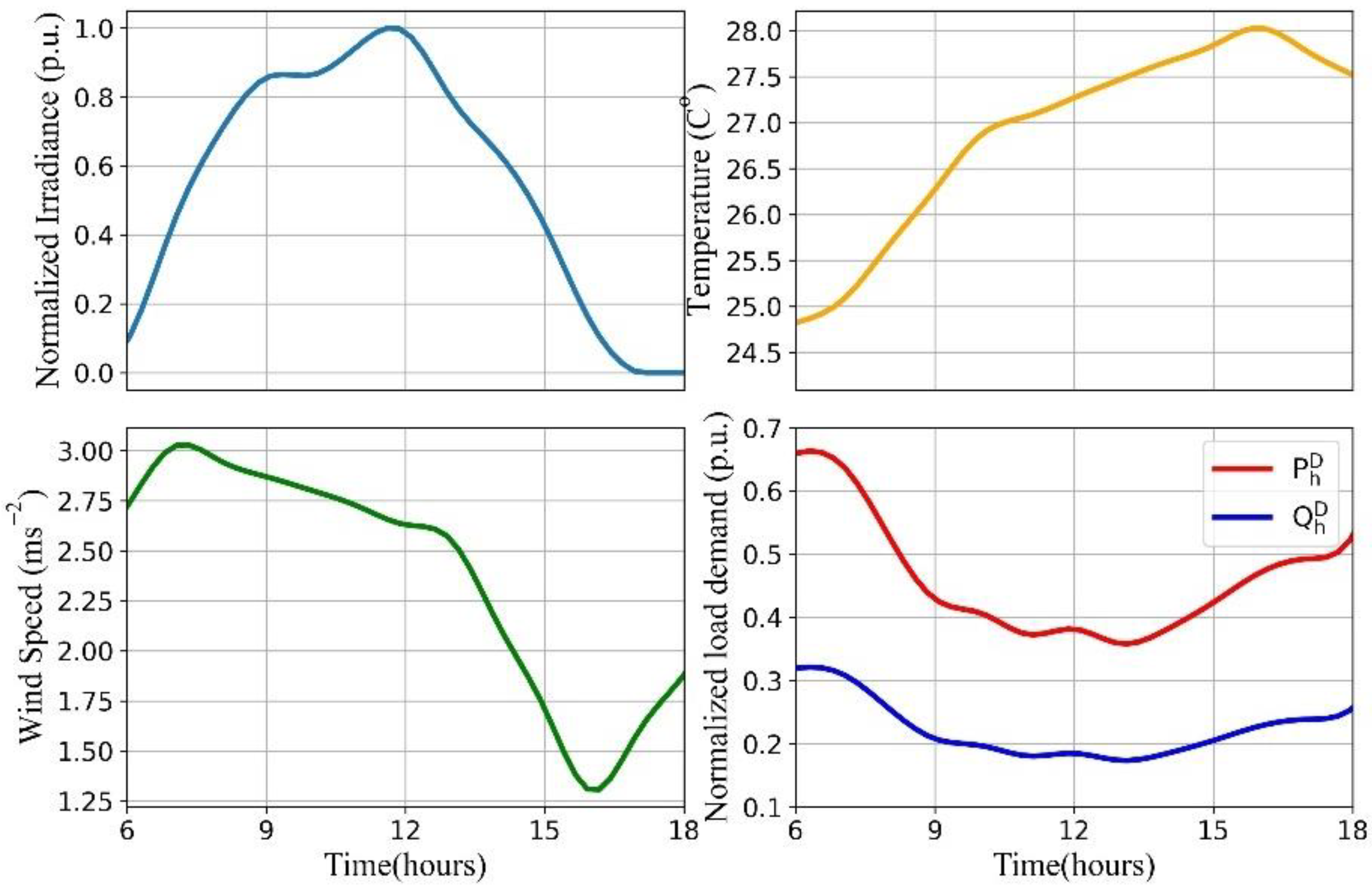
    • To that end, a simulation model for obtaining PVHC with varied PV generation, voltage control, and DLR on a real PV-rich distribution network is outlined, together with real system characteristics and real-time weather data. Furthermore, the obtained PVHCs under indicated enhancing strategies were compared.
  • The suggested approach is utilized together with rephasing PV connections to extend the PVHC in LVDN.
    • To the best of the author’s knowledge, PV re-phasing has never been utilized to improve PVHC and has never been involved in conjunction with voltage control and DLR.
  • The energy capture with various PVHC boosting approaches is produced to illustrate the economic benefit of the integration of voltage control, DLR, and rephasing.

2. Methodology

2.1. Probabilistic Assessment of Voltages and Currents to Enhance PVHC

Owing to the variability and uncertainty of the capacity and the connecting location of PV panels, a probabilistic method based on Monte Carlo simulation was utilized in this study to examine the nodal voltages and branch currents of the LVDN. The location (i.e., the connecting node) and the phase of a particular household h   ( H ) are indicated by n h   ( N ) and h   (   = { A , B , C } ) , respectively. All LVDN-connected households are single-phase, which is the most prevalent type of household in urban areas. P h D and Q h D denotes the active and reactive power demand of each household which was preset by a power factor. P h G presents the generated power by the households with PV installations (i.e., h G H ). The maximum power that could be generated from a given household depends on the maximum available power at the moment ( P h G ¯ ) and the inverter capacity ( C h P V ) . If there is no active power curtailment, then P h G is equal to P h G ¯ .
In the Monte Carlo simulation, the PV capacities, and also the associated nodes and phases to where and which the PV installations are coupled were produced at random, and a large number of PV deployment scenarios were formed by varying the random factors stated above. The total PV capacity attached to the LVDN was kept constant in all deployment scenarios. After each snapshot power flow simulation, all nodal voltages and branch currents for each network model with a specific scenario were retrieved and saved for further analysis. This procedure was repeated by varying the total PV capacity attached to the network and was assessed the voltage and ampacity limit breaches.

2.2. RPC and APC of PV Inverters

The PV inverters’ voltage control method has a significant impact on the LVDN’s PVHC. These methods are designed to actively limit the breaches in the voltage envelope at the PCC by controlling the PV inverters’ active and reactive powers based on the local voltage measurement. The range of active and reactive power generation of the hth PV system could express as follows:
( P h , t G ) 2 + ( Q h , t G ) 2 = ( C h P V ) 2
where, ( P h , t G ) 2 and ( Q h , t G ) 2 represent the square of the generated active power and generated or absorbed reactive power of the PV installation at the hth household on tth time. C h P V is the inverter capacity of the PV installation at the hth household. Nonetheless, the Q i , t G , which is the reactive power output at a given moment depends on P i , t G ¯ as follows.
Q i , t G = P i , t G ¯ × tan ( acos ( P F h ) )
where P F h is the pre-defined power factor of the PV system at hth household. When in RPC mode, the PV inverter injects or absorbs reactive power if the PCC voltage varies below or beyond specified thresholds, as shown in Figure 1 (red curve). It could be mathematically presented by a piecewise linear function as in (3).
Q h , t G = f ( V i , t ) = { + Q h , m a x G                                         ; V i , t < V 0 q ( V 1 q V i , t V 1 q V 0 q ) Q h , m a x G ; V 0 q < V i , t < V 1 q 0                                                             ; V 1 q < V i , t < V 2 q ( V 3 q V i , t V 3 q V 2 q ) Q h , m a x G ; V 2 q < V i , t < V 3 q Q h , m a x G                                         ; V 3 q < V i , t < V 4 q
where, Q h , m a x G = min ( Q h , t G , Q i , t G ¯ ) and the + and sign convention denotes the absorption and the injection.
Similarly, in the APC mode, the active power is curtailed if the PCC voltage varies below or beyond the specified threshold, as shown in Figure 1 (blue curve). The piecewise linear function for APC is given as follows.
P h , t G = f ( V i , t ) = { P h , t G ¯                                         ; V i , t < V 0 P ( V 1 P V i , t V 1 P V 0 P ) P h , t G ¯ ; V 0 P < V i , t < V 1 P 0                                                 ; V 1 P < V i , t < V 1 P

2.3. Parallel Operation of PV Inverters and OLTC

It is assumed that the RPC and APC modes of the inverters have fixed voltage setpoints. In case if the above modes are unable to keep the nodal voltages within the envelope, the OLTC operates and triggers its positions to regulate the voltages of the LVDN. This control approach decreases the OLTC’s wear and tear by giving precedence to the PV inverters to regulate the voltage.

2.4. Time Series Evaluation (Deterministic Assessment) of DLR and VC Methods to Enhance PVHC and Energy Capture

To give real-time ratings to LVDN lines, it is crucial to analyze the physical properties and characteristics that constitute these ratings. The maximum current that a conductor could handle is determined by the maximum allowable conductor temperature, above which the conductor may experience excessive sag or annealing in the long run. Different standards have been published on this and “IEEE 738” [46] is used in this study since it is one of the prominent technical standards on the same that uses the worst-case weather conditions; 80 °C as the maximum allowable conductor temperature, 0.6 ms−1 as the wind speed, and 30 °C as the ambient temperature.
Static line rating (SLR) is the current rating obtained under specified environmental conditions at the highest allowable conductor temperature. The thermal state of an overhead conductor can be determined by considering the conductor’s heat absorption and heat loss (i.e., heat balance). Different heating and cooling effects, as indicated in Figure 2, affect conductor heat balance depending on meteorological conditions.
The steady-state heat balance equation (HBE) in the IEEE 738 standard is given by,
q r + q c = q s + q l
where, q r and q c are the radiative and convective heat losses while q s and q l are the solar heat gain and the joule heating. This HBE could be further elaborated as,
q r + q c = q s + I 2 R a c T c
where I , R a c , and T c are the current flowing through the conductor, a function of conductor temperature and conductor temperature. The R a c could be calculated according to (7).
R a c = R d c K a c [ 1 + α 0 ( T c T 0 ) ]
where, R d c , K a c , α 0 , T c , and T 0 are the dc resistance at the reference temperature, the ratio between the ac and dc resistance, temperature coefficient of the resistance, conductor temperature, and initial temperature respectively. The solar heat gain is calculated using (8) and the conductive heat loss is calculated as Equations (9)–(11).
q s = α s D ( S b + S d )
q c = h π D ( T c T a )
h = [ λ 0.64 R e 0.2 + 0.2 R e 0.61 D ] K w d
R e = D ( w V f )
The α s , D , S b , and S d are the solar absorption, conductor diameter, beamed, and diffused solar radiations. Further, λ , T a , K w d , w , and V f are the thermal conductivity of ambient air, ambient temperature, wind direction, wind speed, and kinematic viscosity of air.
q r = σ ε π D [ ( T c + 273 ) 4 ( T a + 273 ) 4 ]
where σ and ε are the Stephan Boltzmann constant and the emissivity. By rearranging the terms in the steady-state HBE in (5), the DLR of the overhead line is determined as in (13).
D L R ( I r a t i n g ) = 1 R a c T m a x ( q r + q c q s )
The maximum allowable current of a conductor at real-time weather conditions which is called the DLR is determined at the maximum conductor temperature ( T m a x ). According to the standards, T m a x is 75–80 °C and is determined by the operator.

3. Case Study

3.1. Test Cases and Scenarios
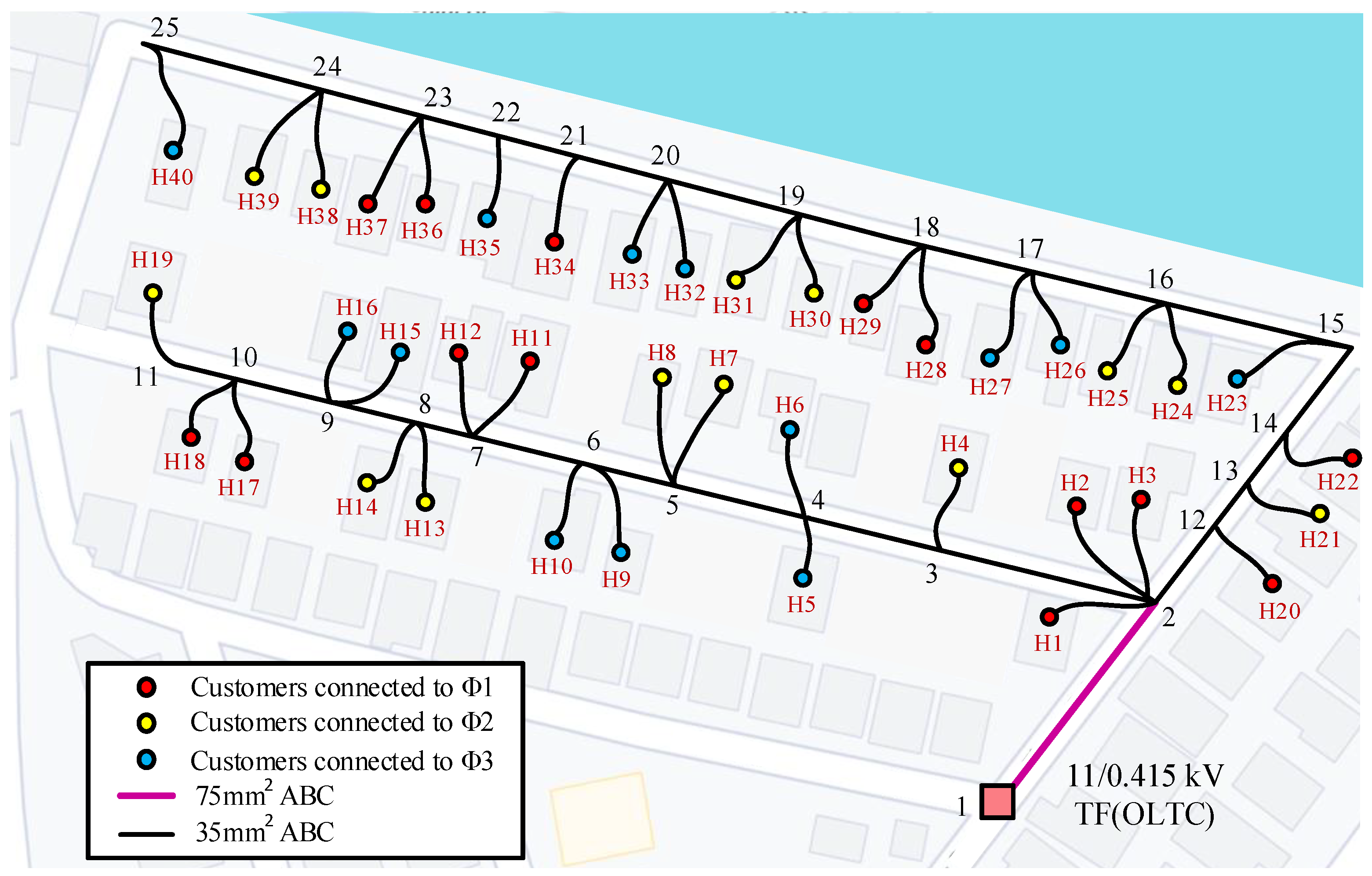
In this study, two test cases were investigated. Initially, a probabilistic technique was used to evaluate the influence of the stochastic effect of PV installations on voltage and ampacity, which directly affect PVHC. In this method, the PV installations are assigned using the Monte Carlo technique. The size, placement, and number of PVs in LVDN are all unpredictable variables decided by the customers’ choices and not under the network operator’s control. As a result, future PV installations are fraught with uncertainty. A Monte Carlo simulation takes into account a wide variety of possibilities and aids in the reduction of uncertainty. Therefore, from the perspective of PVHC, it provides flexibility in assessing future PV scenarios in LVDNs with high PVHCs. When compared to other approaches for random allocation, the Monte Carlo method exhibits uniform randomness. It is extremely adaptable, allowing to adjust risk assumptions across all parameters and so model a wide range of possible outcomes. Further to that, this method is simple, intuitive, and is quite easy to understand.
Following that, the deterministic approach was used (i.e., PVs were installed at known locations) to investigate the capabilities of the aforementioned voltage control methods, as well as the feasibility of using the DLR in overhead power lines and rephasing to increase the ampacity.
Accordingly, the test cases were mainly divided as (a) Probabilistic impact assessment and (b) Deterministic impact assessment. They are further subdivided as in Table 1.
In the probabilistic impact assessment, all households ( h G H ) are permitted to connect a PV system to the grid, which varies in a specified inverter capacity range. The PV sites are known in advance ( G H ) in the deterministic method, and the total size of the PV systems integrated into the LVDN varies according to the scenario.

3.2. Test Network

The simulations employed a part of the urban LV distribution network topology (Lotus Grove) in Sri Lanka. Sri Lanka is a tropical nation with consistent irradiance throughout the year with the sun beating down directly over the country in March and April. Residents have been encouraged to install a PV system in their homes owing to incentives and relaxed policies on roof-top solar PV. Currently, the installation process has been hampered with the technical constraints, thus providing an ideal platform to study alternative ways of enhancing PVHC. Even though a network from Sri Lanka is used for this case study, the methodology and findings can be universally adopted. This Lotus Grove network was only used as a case study to demonstrate the concepts outlined in this study. As this is not a proper design, the exact geographic data was ignored.
The LVDN consists of a single OLTC transformer and 25 nodes, as illustrated in Figure 3. The given distribution system’s root node was symbolized by a “Pink Square—1st node“ and was linked to the secondary side of the MV/LV Transformer with a rated capacity of 250 kVA and a voltage rating of 11/0.415 kV. The primary side of the transformer was retained at a constant voltage (1 p.u.). The thick, solid black lines in Figure 3 depict three-phase overhead lines wired by 35 mm2 ariel bundled cables (ABC), which deliver electricity to single-phase households and the purple colored line depicts a 70 mm2 ABC cable that ends by merging into two 35 mm2 ABC laterals. There are 40 households ( H ) connected to this distribution system and the households associated with each phase are portrayed by red (Phase A), yellow (Phase B), and blue (Phase C) color circles. The reactive power consumption by the households was limited by a preset fixed power factor of 0.9.

4. Simulation Results and Discussions

In this section, a detailed comparison of the proposed impact assessment methodologies which are based on probabilistic and deterministic considerations are provided with an emphasis on the voltage and the ampacity of the distribution system. An RPC scheme that ensures 100% injection/absorption of available reactive power below/beyond the voltage statutory limits of LVDNs in Sri Lanka (i.e., 0.94 p.u., 1.06 p.u.) was used. The APC scheme curtails all the available active power when the voltage reaches 1.06 p.u. These points were chosen concerning the voltage statutory limits for LVDNs provided by the electric utility of Sri Lanka to guarantee that the voltage at the point of connection is within the regulatory limitations. Peak irradiance and peak load are taken into account for the snapshot simulations in probabilistic assessment, while the assessment period in the deterministic method corresponds to 6 h and 18 h on a weekday, as it necessitates voltage control and changes in DLR. The simulation time step for deterministic assessment is set to 15 min and the power flow simulations are performed using OpenDSS (Open Distribution Simulation System).

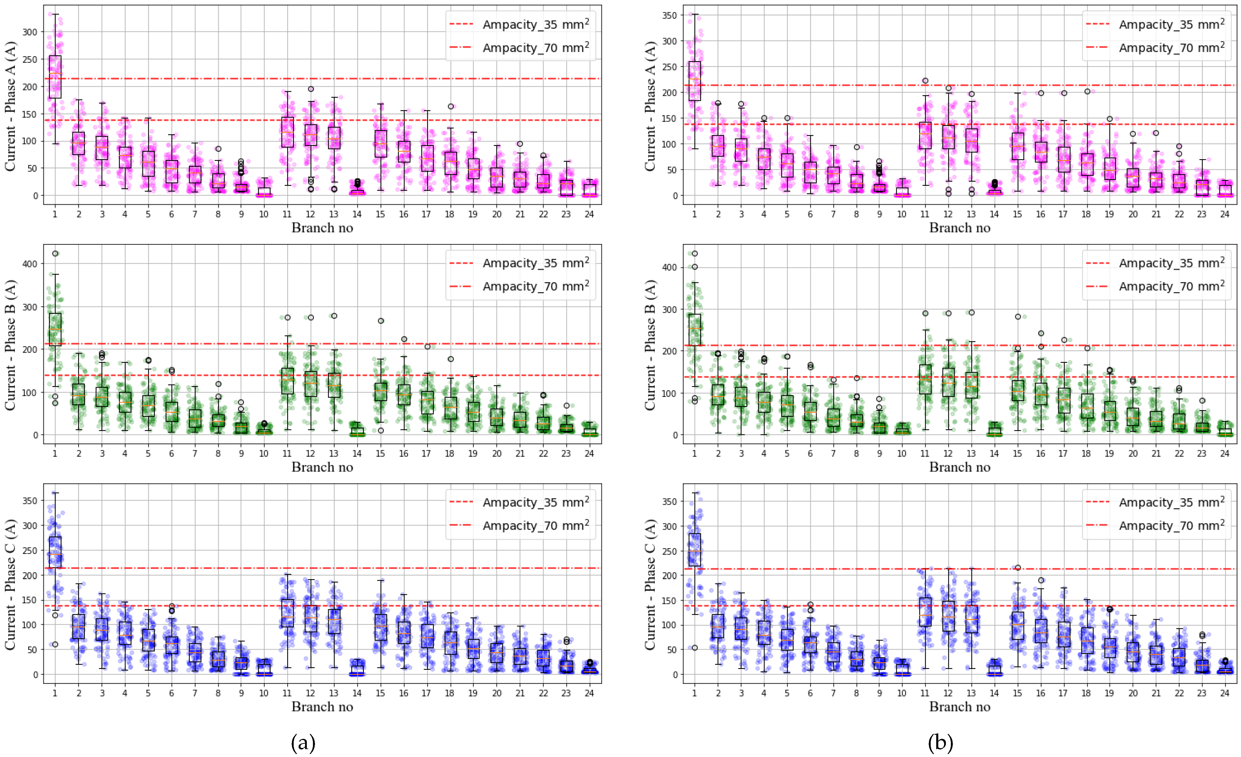
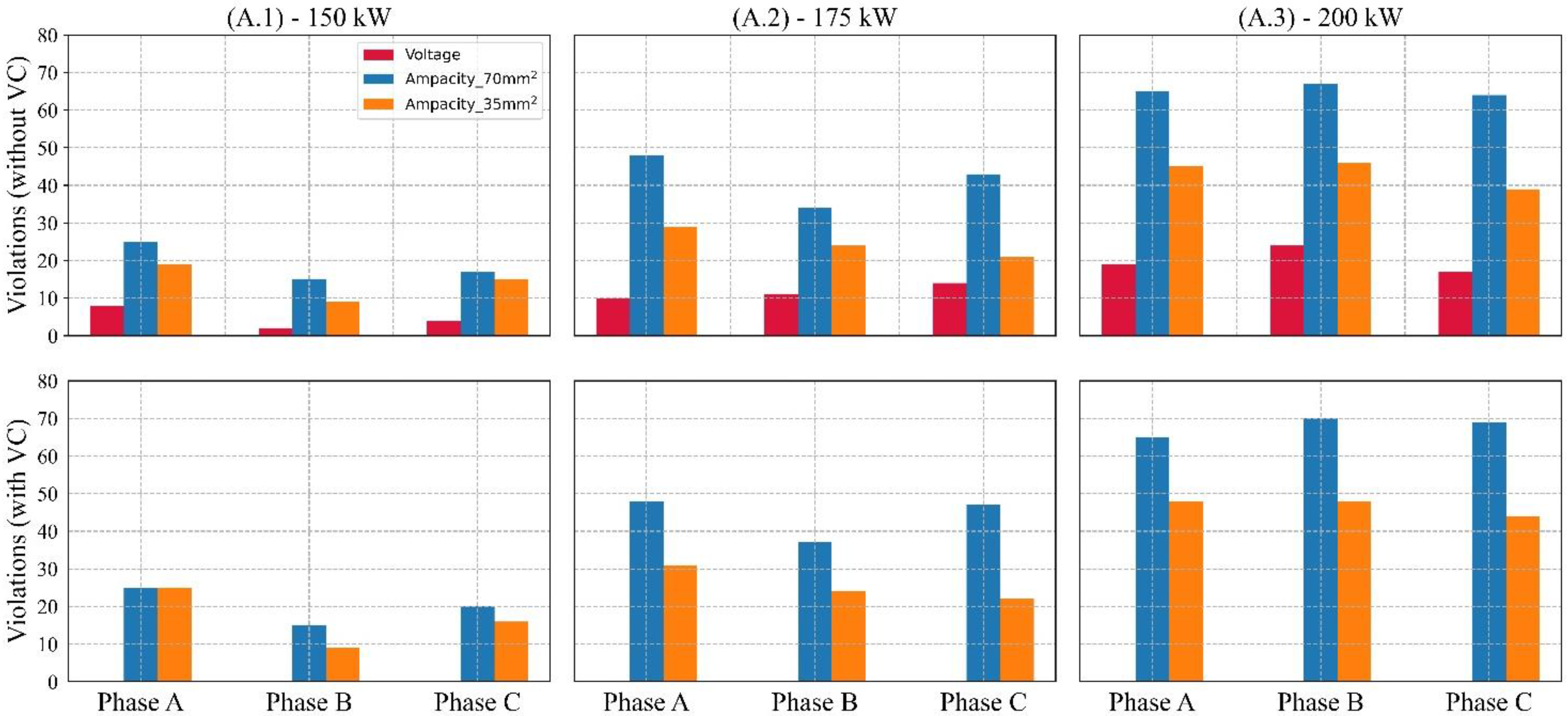
4.1. (a)—Probabilistic Assessment of Voltages and Currents

The capacity of each PV system was varied randomly between 3 and 8 kW, and they were uniformly dispersed in the distribution system while randomly picking the phase to which they are connected. During this assessment, the total capacities of all the PV systems connected to the network were maintained at a constant level. Moreover, the power demands in all the households and the PV capacity were kept constant at their peaks to evaluate the detrimental impacts in each scenario. For each defined total cumulative PV capacity, hundred Monte Carlo simulations were performed, and the nodal voltages and branch currents were extracted. Thereafter, the violations in the voltage statutory limit and the cable ampacities were computed in each simulation. Figure 4 and Figure 5 illustrate the variation of nodal voltages and branch currents for 100 Monte Carlo simulations with different random PV deployment scenarios, (a) with and (b) without voltage control at a 200 kW of total installed PV capacity.
Each graph utilized three distinct colors to depict the three phases, and the regulatory limits are marked in red with unique line styles. In the absence of voltage regulation, all three-phase voltages exceed the upper voltage limit, with maximums at feeder ends of approximately 1.1 p.u. In terms of branch currents, the breaches emerged at the feeder beginning as a result of excess energy being transferred to the transformer. It was apparent that the application of voltage control resulted in a decrease in nodal voltages and an increase in ampacity violations (i.e., increased number of scatter points above the ampacity limits). The number of violations was counted and shown in Figure 6 after performing identical simulations for 150 kW, 175 kW, and 200 kW total installed PV capacities.
As demonstrated in Table 1, in the first test scenario (A.1) under probabilistic assessment, the overall PV capacity was adjusted to 150 kW, and voltage limit breaches were recorded in all three phases. The number of ampacity violations in 70 mm2 cable is higher than in 35 mm2 cable since it is the most upstream cable section that delivers power to the two 35 mm2 laterals. However, owing to the increased PV capacity in the network in the other two cases, which was 175 kW (A.2) and 200 kW (A.3), a greater number of violations were noticed and illustrated the same trend. It is clearly shown in the subplots under violations (“without VC”) in Figure 6.
Following that, the RPC method according to the aforementioned voltage statutory limits was used for all Monte Carlo simulations, and the number of voltage violations was evaluated. As shown in the subplots under violations (“with VC”) in Figure 6, the method was shown to be capable of removing breaches in all three scenarios; (A.1), (A.2), and (A.3). However, controlling the voltage at PCCs above 200 kW is challenging. Furthermore, as shown in Figure 6, there is an increased incidence of breaches in ampacity with voltage control. As a result, it is possible to conclude that the violations in ampacity continue to impede PVHC, despite the ability to eliminate the influence of voltage violations.

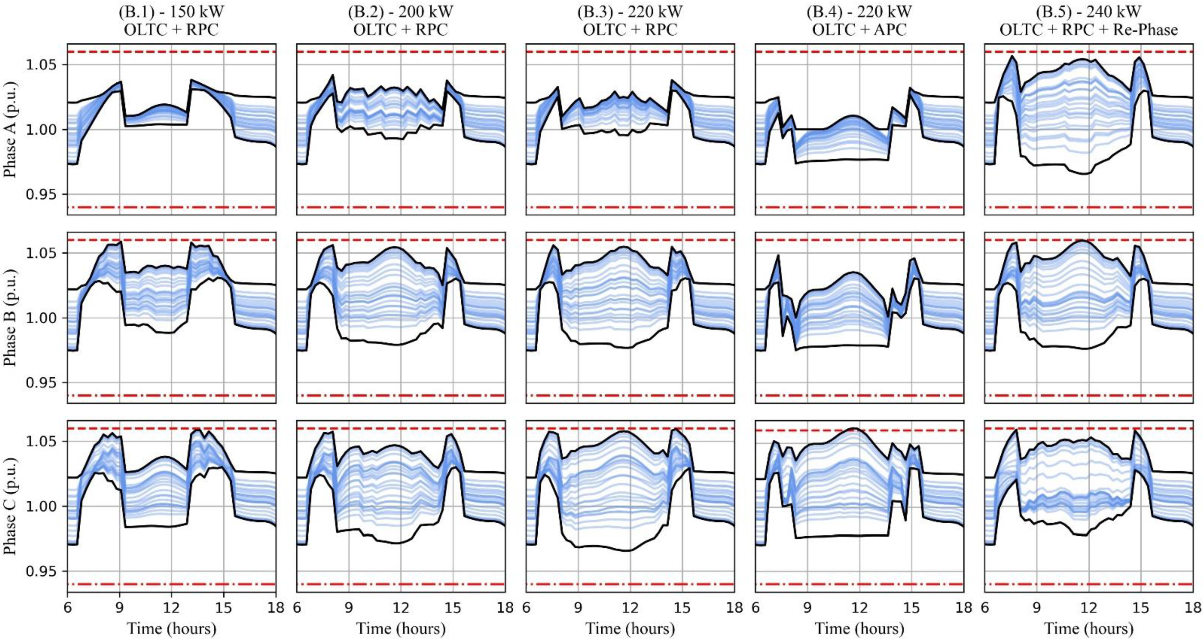
4.2. (b)—Deterministic Assessment of Voltages and Currents

Deterministic techniques use a model with known and fixed input data to assess the influence of solar PV on a particular LVDN. The said LVDN, household power demand, and variation of the weather (i.e., solar irradiance and wind speed) employ known single input values to produce single output values. Furthermore, for a given installed PV capacity, the size, location, and property of every individual solar PV system are expected to be known. Figure 7 depicts the used irradiance, temperature, wind speed, and load demand variations during the assessment period, and these data were used to calculate the DLR using (13). It was assumed that all of the PV panels on the rooftops in the LVDN are perpendicular to the incidence irradiance of the sun, where the PV panels get the peak irradiance. Moreover, all the meteorological and electrical data are related to a weekday when the load demand of the residences is significantly lower during peak irradiance time in typical resident LVDNs. As a result, voltage and thermal control are required to restore the LVDN to normal operation.
Figure 8 depicts the computed DLR for the specified simulation time (6 h to 18 h) for 35 mm2 ABC cable based on the weather circumstances according to the data in [47] which are shown in Figure 7. It should be mentioned that the DLR limit in this research is set at 75% of the computed DLR of 35 mm2 ABC cable.
As stated in the methodology section, the variation of the PV sizes at known locations and the corresponding phases are given in Figure 9. The subplots indicate the PV sizes and phases for total capacities of (a) 150 kW, (b) 200 kW, (c) 220 kW, and (d) 240 kW, respectively, while the last subplot depicts the altered PV phases (re-phased) with a black color ring around the phase representation dot.
The simulations were performed using the provided irradiance, temperature, wind speed, load demand, electrical and topological LVDN data, and the PV data. The extracted variations in voltage and branch current in the LVDN under five different scenarios are illustrated in Figure 10 and Figure 11, respectively. The red colored dashed line and dashed-dotted line in the voltage profiles in Figure 10 reflect the upper and lower voltage statutory limitations, respectively. All of the nodal voltages in the LVDN are indicated by all of the subplots and the maximum and minimum voltages. When (B.1)—150 kW, (B.2)—200 kW, and (B.3)—220 kW total PV capacity is connected, the coordinated OLTC and RPC approaches are used to regulate the nodal voltages of the three phases in the LVDN within the specified limits as shown in Figure 10. It was evident that as the PV capacity increased, the nodal voltages approached the upper voltage limit.
Figure 11 depicts the variations in branch currents that correspond to the previously described test scenarios under test case B in Table 1. In subplots in Figure 11, the blue dashed line indicates the SLR, whereas the orange dashed-dotted line represents 75% of the calculated DLR. Further to that, the maximum values in currents are shown in black solid lines.
As shown in Figure 11, in (B.1) test scenario, there are no SLR violations with a total PV capacity of 150 kW with voltage control through OLTC and RPC. The branch current surpasses the SLR of 138A for 35 mm2 in two of three phases (i.e., phases B and C) under the (B.2) test scenario, which connects 200 kW PV capacity to the network with OLTC + RPC and approaches 75% of the calculated DLR at peak irradiance. The SLR breeches in Figure 11 are shown by a yellow rectangle, the location of which corresponds to the violation time. The branch currents, however, violate the DLR with a PV capacity of 220 kW (B.3) in phase C, as indicated by a red rectangle. From the results obtained under these three test cases, it could suggest that SLR has a significant influence on PVHC early on, and then dynamic line rating inhibits PVHC even when the voltages are at their needed levels.
The APC is one of the methods to increase the PVHC of the network when a line rating violation occurs, which is a simple yet effective approach to alleviate technical difficulties with voltage and ampacity. However, from the standpoint of prosumers with PV installations, this is not a desirable technique because it lowers revenues from PV power production. The voltage profiles in (B.4) with a total capacity of 220 kW indicate a decrease owing to APC, and the ampacity violations that occurred with RPC have been removed by two phases, but with only one phase exhibiting SLR violations. Despite the fact that it provides headroom for raising PVHC by way of branch currents till DLR in this case, the voltage acts as a deterrent by reaching the upper limit in one phase. Nonetheless, the re-phasing, as well as the voltage control using OLTC and RPC methods used in the test case (B.5), appeared to have the greatest influence on PVHC because of the balanced PV installation in all phases. Figure 9d depicts the re-phased PV installations in black circles, with a total installed PV capacity of 240 kW. In that case (B.5), all of the voltage profiles in Figure 10 are lower than the upper voltage limit, and the branch currents in Figure 11 exceeded the SLR, but not the DLR. This illustration suggests that re-phasing, in conjunction with voltage control through OLTC and RPC techniques, has the capacity to enhance PVHC in an LVDN without causing any technical glitches with voltages and currents. The increments of PVHC compared to the only voltage control are listed in Table 2.
As an extension of this simulation study, the energy under various metrics is measured throughout the course of a complete day under each test case described by the deterministic approach to show the efficacy of the proposed approach. Those metrics are solar generation, load demand, grid-import, grid-export, and network loss, and they are presented in Figure 12.
The total energy required by the load throughout the day is consistent in all the test scenarios, and as well as the grid import, which occurs during sundown. Nonetheless, the solar PV energy varies with the PVHC, except in (B.4) scenario (i.e., 220 kW with OLTC + APC) where APC and voltage control are employed. It generates significantly less energy than the (B.3) scenario (i.e., 220 kW with OLTC + RPC) which utilized the same PVHC. The maximum solar energy was produced with a higher PVHC, which was reported in (B.5) scenario with rephasing. During solar energy generation, reverse power flow occurs, and therefore grid-exported energy changes with the PVHC. Furthermore, the network energy loss exhibits a similar pattern to solar energy, which decreases with APC employment, showing a clear relationship between active power and network energy loss.

5. Conclusions

Traditionally, PVHC has been constrained primarily by voltage limitations, and solutions have been explored using OLTC, RPC, and APC, while thermal breaches in LVDN cables have gone unnoticed. Despite the fact that it takes into account thermal constraints, utility caps PVHC at the SLR of the cable resulting in an underestimate of PV accommodation. However, the thermal limit’s behavior has been influenced by meteorological conditions, and as a result, the notion of the DLR has been proposed. This paper analyzes the integrated usage of voltage control and DLR in an LVDN to maximize the PVHC by comprehensively considering the technical limitations and the meteorological factors. Based on the real electrical, topological, and meteorological data, a case study was conducted, and the conclusions are as follows.
  • Voltage and SLR violations in LVDNs were induced by the unpredictability of PV connections and the intermittent nature of sunlight, and they were examined using a probabilistic methodology based on the Monte Carlo approach. It has been revealed that with greater PVHCs, the percentage of infractions increases, and mitigation of the aforementioned issues becomes more challenging.
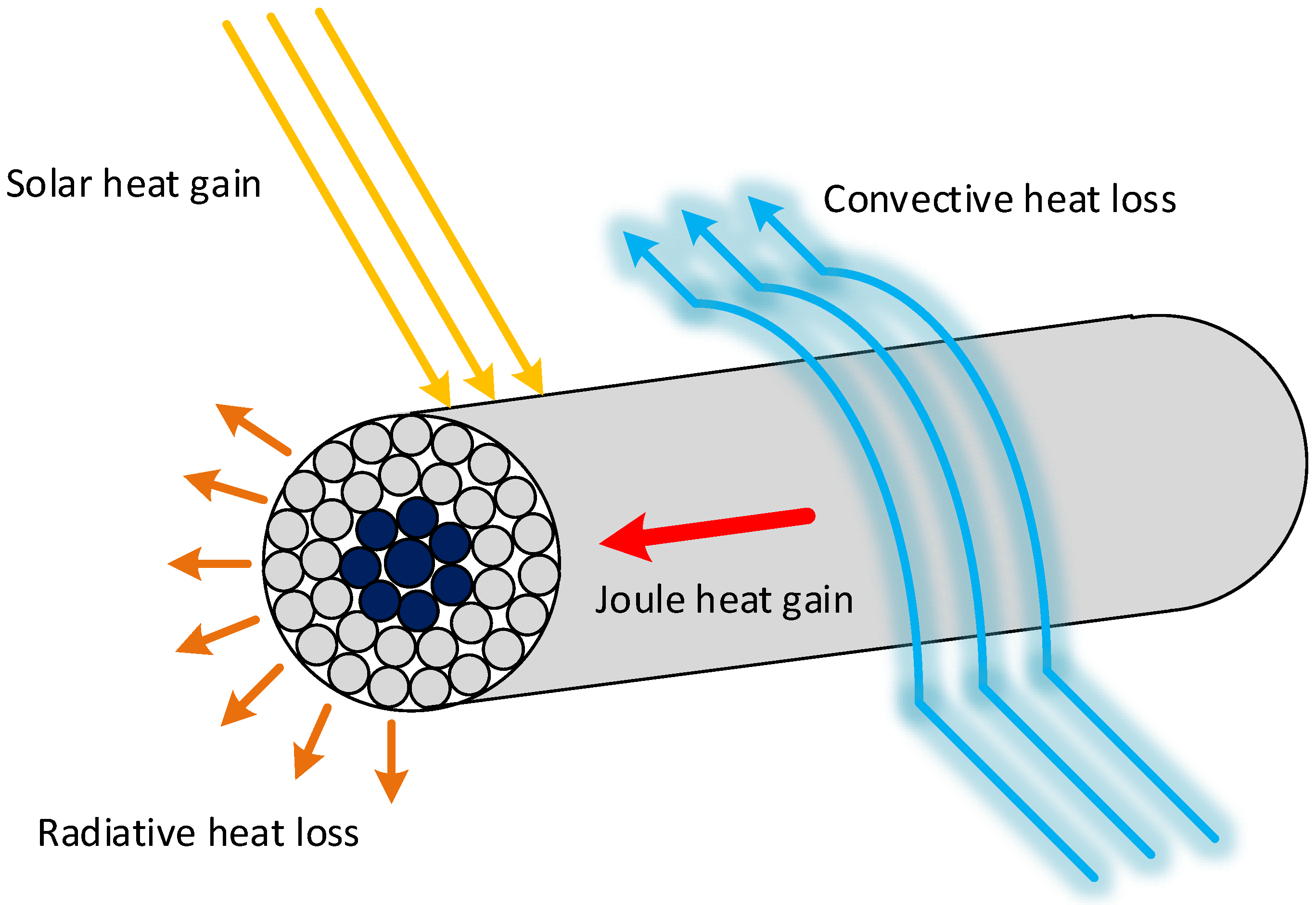
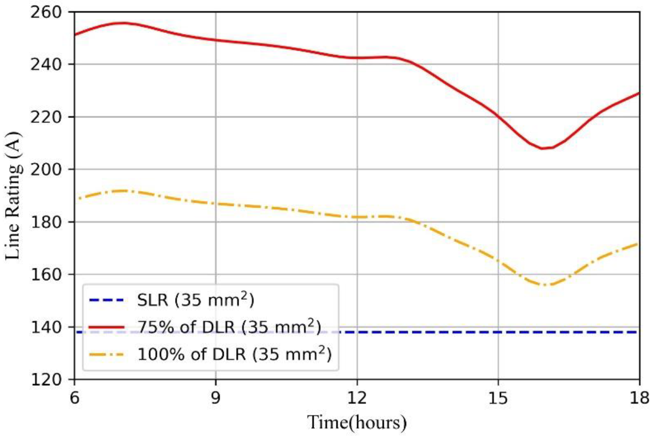
  • In terms of meteorological characteristics, the DRL raises the current carrying capacity of a cable over SLR at certain time instants and eliminates the risk of thermal congestion, hence indirectly giving investment advantages.
  • The given simulation model could be used to examine both voltage and current in order to raise PVHC, and the various methodologies utilized in the deterministic study (i.e., OLTC, RPC, APC, and re-phasing) indicate their ability to improve PVHC.
  • The usage of OLTC, RPC, and re-phasing with the DRL has successfully expanded the scope to enhance PVHC in an LVDN and according to the case study, it depicted a 60% increase in PVHC compared to the case with only voltage control.
  • The energy captured in a PV system could be maximized by rephasing with the OLTC and RPC, providing households with extra-economic benefits.
  • The proposed integrated voltage control and DLR technique postponed grid reinforcement and permitted a large PVHC.

Author Contributions

Conceptualization, E.K. and A.W.; methodology, E.K., A.W. and J.E.; software, validation, formal analysis, E.K. and A.W.; writing—original draft preparation, E.K. and A.W.; writing—review and editing, E.K., A.W. and J.E.; supervision, J.E.; project administration, J.E. All authors have read and agreed to the published version of the manuscript.

Funding

This research received no external funding.

Institutional Review Board Statement

Not applicable.

Informed Consent Statement

Not applicable.

Data Availability Statement

This study did not report any data.

Conflicts of Interest

The authors declare that they have no known competing financial interest or personal relationships that could have appeared to influence the work reported in this article.

Nomenclature

ABCAriel Bundle Cable
APCActive Power Curtailment
DLRDynamic Line Rating
HBEHeat Balance Equation
LVLow Voltage
LVDNLow Voltage Distribution Network
MVMedium Voltage
OLTCOn-Load Tap Changer
PCCPoint of Common Coupling
PECPower Electronic Converter
PVPhotovoltaic
PVHCPhotovoltaic Hosting Capacity
RPCReactive Power Compensation
SLRStatic Line Rating

References

  1. Li, H.X.; Edwards, D.J.; Hosseini, M.R.; Costin, G.P. A Review on Renewable Energy Transition in Australia: An Updated Depiction. J. Clean. Prod. 2020, 242, 118475. [Google Scholar] [CrossRef]
  2. Musa, S.D.; Zhonghua, T.; Ibrahim, A.O.; Habib, M. China’s Energy Status: A Critical Look at Fossils and Renewable Options. Renew. Sustain. Energy Rev. 2018, 81, 2281–2290. [Google Scholar] [CrossRef]
  3. 2030 Climate & Energy Framework | Climate Action. Available online: https://ec.europa.eu/clima/policies/strategies/2030_en (accessed on 17 September 2021).
  4. International Renewable Energy Agency—IRENA. Future of Solar Photovoltaic; International Renewable Energy Agency: Abu Dhabi, United Arab Emirates, November 2019. [Google Scholar]
  5. REN21. Renewables 2020 Global Status Report; REN21 Secretariat: Paris, France, 2020. [Google Scholar]
  6. Wang, Y.; Zhao, T.; Ju, C.; Xu, Y.; Wang, P. Two-Level Distributed Volt/Var Control Using Aggregated PV Inverters in Distribution Networks. IEEE Trans. Power Deliv. 2020, 35, 1844–1855. [Google Scholar] [CrossRef]
  7. Tonkoski, R.; Turcotte, D.; El-Fouly, T.H.M. Impact of High PV Penetration on Voltage Profiles in Residential Neighborhoods. IEEE Trans. Sustain. Energy 2012, 3, 518–527. [Google Scholar] [CrossRef]
  8. Samadi, A.; Eriksson, R.; Söder, L.; Rawn, B.; Boemer, J. Coordinated Active Power-Dependent Voltage Regulation in Distribution Grids with PV Systems. IEEE Trans. Power Deliv. 2014, 29, 1454–1464. [Google Scholar] [CrossRef]
  9. Jain, A.K.; Horowitz, K.; Ding, F.; Gensollen, N.; Mather, B.; Palmintier, B. Quasi-Static Time-Series PV Hosting Capacity Methodology and Metrics. In Proceedings of the 2019 IEEE Power and Energy Society Innovative Smart Grid Technologies Conference, Gramado, Brazil, 15–18 September 2019. [Google Scholar] [CrossRef]
  10. Bollen, M.H.J.; Rönnberg, S.K. Hosting capacity of the power grid for renewable electricity production and new large consumption equipment. Energies 2017, 10, 1325. [Google Scholar] [CrossRef] [Green Version]
  11. Arshad, A.; Lehtonen, M. A Stochastic Assessment of PV Hosting Capacity Enhancement in Distribution Network Utilizing Voltage Support Techniques. IEEE Access 2019, 7, 46461–46471. [Google Scholar] [CrossRef]
  12. Ali, A.; Mahmoud, K.; Lehtonen, M. Maximizing Hosting Capacity of Uncertain Photovoltaics by Coordinated Management of OLTC, VAr Sources and Stochastic EVs. Int. J. Electr. Power Energy Syst. 2021, 127, 106627. [Google Scholar] [CrossRef]
  13. Zhang, C.; Xu, Y. Hierarchically-Coordinated Voltage/VAR Control of Distribution Networks Using PV Inverters. IEEE Trans. Smart Grid 2020, 11, 2942–2953. [Google Scholar] [CrossRef]
  14. Xu, Y.; Dong, Z.Y.; Zhang, R.; Hill, D.J. Multi-Timescale Coordinated Voltage / Var Control Of. IEEE Trans. Power Syst. 2017, 32, 4398–4408. [Google Scholar] [CrossRef]
  15. Kabir, M.N.; Mishra, Y.; Ledwich, G.; Dong, Z.Y.; Wong, K.P. Coordinated Control of Grid-Connected Photovoltaic Reactive Power and Battery Energy Storage Systems to Improve the Voltage Profile of a Residential Distribution Feeder. IEEE Trans. Ind. Inform. 2014, 10, 967–977. [Google Scholar] [CrossRef]
  16. IEEE 1547-2018—IEEE Standard for Interconnection and Interoperability of Distributed Energy Resources with Associated Electric Power Systems Interfaces. Available online: https://standards.ieee.org/standard/1547-2018.html (accessed on 17 September 2021).
  17. Common Functions for Smart Inverters, Version 2. Available online: https://www.epri.com/research/products/1023059 (accessed on 17 September 2021).
  18. Almeida, D.; Pasupuleti, J.; Ekanayake, J. Comparison of Reactive Power Control Techniques for Solar Pv Inverters to Mitigate Voltage Rise in Low-Voltage Grids. Electronics 2021, 10, 1569. [Google Scholar] [CrossRef]
  19. Hu, Y.; Liu, W.; Wang, W. A Two-Layer Volt-Var Control Method in Rural Distribution Networks Considering Utilization of Photovoltaic Power. IEEE Access 2020, 8, 118417–118425. [Google Scholar] [CrossRef]
  20. Anonas, S.D.S.; Orillaza, J.R.C. Solar PV Integrated Hosting Capacity Analysis with Volt-VAr Compensation. In Proceedings of the International Conference on Innovative Smart Grid Technologies ISGT Asia 2018, Singapore, 22–25 May 2018; pp. 1044–1049. [Google Scholar] [CrossRef]
  21. Almeida, D.; Pasupuleti, J.; Ekanayake, J.; Karunarathne, E. Mitigation of Overvoltage Due to High Penetration of Solar Photovoltaics Using Smart Inverters Volt/Var Control. Indones. J. Electr. Eng. Comput. Sci. 2020, 19, 1259–1266. [Google Scholar] [CrossRef]
  22. Gush, T.; Kim, C.H.; Admasie, S.; Kim, J.S.; Song, J.S. Optimal Smart Inverter Control for PV and BESS to Improve PV Hosting Capacity of Distribution Networks Using Slime Mould Algorithm. IEEE Access 2021, 9, 52164–52176. [Google Scholar] [CrossRef]
  23. Abad, M.S.S.; Ma, J. Photovoltaic Hosting Capacity Sensitivity to Active Distribution Network Management. IEEE Trans. Power Syst. 2021, 36, 107–117. [Google Scholar] [CrossRef]
  24. Faruque, R.B.; Scudder, M.F.; Ula, S. Real-World Implementation of Advanced PV Curtailment and Reactive Power Control Using Non-Smart PV Inverter: A Case Study. In Proceedings of the 2020 IEEE Power & Energy Society General Meeting, Virtual Event, 3–6 August 2020. [Google Scholar] [CrossRef]
  25. Zabihinia Gerdroodbari, Y.; Razzaghi, R.; Shahnia, F. Decentralized Control Strategy to Improve Fairness in Active Power Curtailment of PV Inverters in Low-Voltage Distribution Networks. IEEE Trans. Sustain. Energy 2021, 12, 2282–2292. [Google Scholar] [CrossRef]
  26. Liu, M.Z.; Procopiou, A.T.; Petrou, K.; Ochoa, L.F.; Langstaff, T.; Harding, J.; Theunissen, J. On the Fairness of PV Curtailment Schemes in Residential Distribution Networks. IEEE Trans. Smart Grid 2020, 11, 4502–4512. [Google Scholar] [CrossRef]
  27. Fatima, S.; Püvi, V.; Lehtonen, M. Review on the PV Hosting Capacity in Distribution Networks. Energies 2020, 13, 4756. [Google Scholar] [CrossRef]
  28. Torquato, R.; Salles, D.; Pereira, C.O.; Meira, P.C.M.; Freitas, W. A Comprehensive Assessment of PV Hosting Capacity on Low-Voltage Distribution Systems. IEEE Trans. Power Deliv. 2018, 33, 1002–1012. [Google Scholar] [CrossRef]
  29. Arshad, A.; Lindner, M.; Lehtonen, M. An Analysis of Photo-Voltaic Hosting Capacity in Finnish Low Voltage Distribution Networks. Energies 2017, 10, 1702. [Google Scholar] [CrossRef] [Green Version]
  30. Kikuchi, S.; Machida, M.; Tamura, J.; Imanaka, M.; Baba, J.; Iioka, D.; Miura, K.; Takagi, M.; Asano, H. Hosting Capacity Analysis of Many Distributed Photovoltaic Systems in Future Distribution Networks. In Proceedings of the 2017 IEEE Innovative Smart Grid Technologies—Asia: Smart Grid for Smart Community, Auckland, New Zealand, 4–7 December 2017; pp. 1–5. [Google Scholar] [CrossRef]
  31. Mohammadi, P.; Mehraeen, S. Challenges of PV Integration in Low-Voltage Secondary Networks. IEEE Trans. Power Deliv. 2017, 32, 525–535. [Google Scholar] [CrossRef]
  32. Weisshaupt, M.J.; Schlatter, B.; Korba, P.; Kaffe, E.; Kienzle, F. Evaluation of Measures to Operate Urban Low Voltage Grids Considering Future PV Expansion. IFAC Pap. 2016, 49, 336–341. [Google Scholar] [CrossRef]
  33. Hoke, A.; Butler, R.; Hambrick, J.; Kroposki, B. Steady-State Analysis of Maximum Photovoltaic Penetration Levels on Typical Distribution Feeders. IEEE Trans. Sustain. Energy 2013, 4, 350–357. [Google Scholar] [CrossRef]
  34. Mahmoudian Esfahani, M.; Yousefi, G.R. Real Time Congestion Management in Power Systems Considering Quasi-Dynamic Thermal Rating and Congestion Clearing Time. IEEE Trans. Ind. Inform. 2016, 12, 745–754. [Google Scholar] [CrossRef]
  35. Teh, J.; Lai, C.M. Reliability Impacts of the Dynamic Thermal Rating System on Smart Grids Considering Wireless Communications. IEEE Access 2019, 7, 41625–41635. [Google Scholar] [CrossRef]
  36. Xu, B.; Ulbig, A.; Andersson, G. Impacts of Dynamic Line Rating on Power Dispatch Performance and Grid Integration of Renewable Energy Sources. In Proceedings of the 2013 4th IEEE/PES Innovative Smart Grid Technologies Europe, Copenhagen, Denmark, 6–9 December 2013; pp. 4–8. [Google Scholar] [CrossRef]
  37. Ausen, J.; Fitzgerald, B.F.; Gust, E.A.; Lawry, D.C.; Lazar, J.P.; Oye, R.L. Dynamic Thermal Rating System Relieves Transmission Constraint. In Proceedings of the 2006 IEEE International Conference on Transmission and Distribution Construction and Live Line Maintenance, Albuquerque, NM, USA, 15–20 October 2006; pp. 1–5. [Google Scholar] [CrossRef]
  38. Zhan, J.; Liu, W.; Chung, C.Y. Stochastic Transmission Expansion Planning Considering Uncertain Dynamic Thermal Rating of Overhead Lines. IEEE Trans. Power Syst. 2019, 34, 432–443. [Google Scholar] [CrossRef]
  39. Ochoa, L.F.; Cradden, L.C.; Harrison, G.P. Demonstrating the Capacity Benefits of Dynamic Ratings in Smarter Distribution Networks. In Proceedings of the 2010 Innovative Smart Grid Technologies Conference, Gothenburg, Sweden, 11–13 October 2010; pp. 1–6. [Google Scholar] [CrossRef] [Green Version]
  40. Jupe, S.C.E.; Kadar, D.; Murphy, G.; Bartlett, M.G.; Jackson, K.T. Application of a Dynamic Thermal Rating System to a 132 kV Distribution Network. In Proceedings of the 2011 2nd IEEE PES International Conference and Exhibition on Innovative Smart Grid Technologies, Manchester, UK, 5–7 December 2011; pp. 1–8. [Google Scholar] [CrossRef]
  41. Zhu, J.; Chow, M.Y.; Zhang, F. Phase Balancing Using Mixed-Integer Programming [Distribution Feeders]. IEEE Trans. Power Syst. 1998, 13, 1487–1492. [Google Scholar]
  42. Soltani, S.H.; Rashidinejad, M.; Abdollahi, A. Dynamic Phase Balancing in the Smart Distribution Networks. Int. J. Electr. Power Energy Syst. 2017, 93, 374–383. [Google Scholar] [CrossRef]
  43. Hooshmand, R.A.; Soltani, S. Fuzzy Optimal Phase Balancing of Radial and Meshed Distribution Networks Using BF-PSO Algorithm. IEEE Trans. Power Syst. 2012, 27, 47–57. [Google Scholar] [CrossRef]
  44. Zhu, J.; Bilbro, G.; Chow, M.Y. Phase Balancing Using Simulated Annealing. IEEE Power Eng. Rev. 1999, 19, 56. [Google Scholar] [CrossRef] [Green Version]
  45. Chaminda Bandara, W.G.; Godaliyadda, G.M.R.I.; Ekanayake, M.P.B.; Ekanayake, J.B. Coordinated Photovoltaic Re-Phasing: A Novel Method to Maximize Renewable Energy Integration in Low Voltage Networks by Mitigating Network Unbalances. Appl. Energy 2020, 280, 116022. [Google Scholar] [CrossRef]
  46. IEEE Power and Energy Society. 738 Standard for Calculating the Current-Temperature Relationship of Bare Overhead Conductors; IEEE Std.: Piscataway, NJ, USA, 2012; ISBN 0738152706. [Google Scholar]
  47. JRC. Photovoltaic Geographical Information System (PVGIS)—European Commission. Available online: https://re.jrc.ec.europa.eu/pvg_tools/en/tools.html#TMY (accessed on 14 September 2021).
Figure 1. Reactive power compensation (RPC—Volt/Var—red) and Active power curtailment (APC—Volt/Watt—blue) schemes.
Energies 15 00134 g001
Figure 2. Heat balance of an overhead conductor.
Energies 15 00134 g002
Figure 3. Single line diagram of the low voltage distribution network (Lotus Grove, Sri Lanka) used for the simulations.
Energies 15 00134 g003
Figure 4. Variation of nodal voltages of the LVDN for (a) without VC and (b) with VC conditions for 100 Monte Carlo simulations—200 kW.
Energies 15 00134 g004
Figure 5. Variation of branch currents of the LVDN for (a) without VC and (b) with VC conditions for 100 Monte Carlo simulations—200 kW.
Energies 15 00134 g005
Figure 6. Number of voltage and ampacity (i.e., SLR) violations occurred for (A.1)—150 kW, (A.2)—175 kW, and (A.3)—200 kW total installed capacities.
Energies 15 00134 g006
Figure 7. Variation of the irradiance, temperature, wind speed, and the load demand during the assessment period.
Energies 15 00134 g007
Figure 8. Line ratings of 35 mm2 ABC cable.
Energies 15 00134 g008
Figure 9. Variation of the PV sizes and the connected phases in different total PV capacities. (a) 150 kW, (b) 200 kW, (c) 220 kW, and (d) 240 kW.
Energies 15 00134 g009
Figure 10. Time-series variation of nodal voltages under different scenarios during PV generation.
Energies 15 00134 g010
Figure 11. Time series variation of branch currents under different scenarios during PV generation.
Energies 15 00134 g011
Figure 12. Energy capture per day under different scenarios during PV generation.
Energies 15 00134 g012
Table 1. Test cases studied.
(A) Probabilistic Assessment(B) Deterministic Assessment
(A.1) 1 150 kW—with/without VC 2(B.1) 3 150 kW—OLTC + RPC
(A.2) 175 kW—with/without VC(B.2) 200 kW—OLTC + RPC
(A.3) 200 kW—with/without VC(B.3) 220 kW—OLTC + RPC
VC 2—voltage control(B.4) 220 kW—OLTC + APC
(B.5) 240 kW—OLTC + RPC + Re-Phase
1 A.1—Scenario 1 in probabilistic assessment, 2 VC—voltage control, 3 B.1—Scenario 1 in deterministic assessment.
Table 2. Summary of the case study.
CaseTotal PV Capacity (kW)Voltage Limit ViolationsSLR Violations/PhaseDLR Violations/PhasePVHC Increment (%)
(B.1) OLTC + RPC150NoNoNoBase case
(B.2) OLTC + RPC200NoYes/B, CNo33.33
(B.3) OLTC + RPC220NoYes/BYes/C46.67
(B.4) OLTC + APC220NoYes/CNo46.67
(B.5) OLTC + RPC + Re-Phase240NoYes/A, B, CNo60.00
Publisher’s Note: MDPI stays neutral with regard to jurisdictional claims in published maps and institutional affiliations.

