Article

Study on Performance of the Thermoelectric Cooling Device with Novel Subchannel Finned Heat Sink

School of Mechanical & Power Engineering, Zhengzhou University, No.100 Kexuedadao Road, Zhengzhou 450001, China
*
Author to whom correspondence should be addressed.
Energies 2022, 15(1), 145; https://doi.org/10.3390/en15010145
Submission received: 16 November 2021 / Revised: 13 December 2021 / Accepted: 20 December 2021 / Published: 26 December 2021

Abstract

:
The thermoelectric refrigeration system is an application of the Peltier effect, and good refrigeration performance is dependent on effective heat dissipation performance. To enhance the cooling performance of the thermoelectric system, this paper designs a new type of finned heat sink, which does not change the overall size of the thermoelectric system. The performance of the refrigeration system under the new fin is tested by experiments under various conditions. During the experiment, the cooling wind speed, the temperature of the hot and cold side of the TEC, the power consumption of the fan, and other parameters were directly recorded through the measuring instrument. The results show that the use of new finned heat sinks can improve the COP of the thermoelectric refrigeration system. Within the scope of the study, the thermal resistance of the new fins can be reduced by 42.6%, and the system COP value can be increased by 22.8%. In addition, increasing the cooling wind speed can further reduce the cold side temperature. Within the research range, the lowest temperature can reach −8.25 °C, but the power consumed by the fan is 166% of that of the conventional fin heat sink refrigeration device.

1. Introduction

The Peltier effect is used in thermoelectric refrigeration (TEC), which is the direct conversion of electrical energy into heat and cold. Thermoelectric refrigeration has many benefits over traditional compressors, which include small size, no noise, long life, precise temperature control, and no need for refrigerant. Because of these advantages, it has a high application value in refrigeration, electronic device cooling, LED lamp cooling, and medical device temperature control. However, its cooling capacity is limited, the coefficient of performance (COP) is lower than that of compressors [1,2], and this obstacle has prompted researchers to pursue new ways to elevate efficiency.
Researchers have conducted extensive research to try to improve the cooling performance of thermoelectric modules. In general, there are two ways to improve thermoelectric cooling efficiency [3]. (1) Change the inherent properties of the materials inside the TEC module, such as changing the geometry and length of thermocouples [4,5], segmenting P-type and N-type thermocouples [6], or researching the constituent materials of thermocouples to improve the figure of merit [7]. However, when the TEC is in use, its inherent internal properties cannot be changed, which requires another method to improve its cooling performance [3]. (2) Based on the existing thermoelectric modules, improve the thermal design and optimization of the thermoelectric refrigeration system. He et al. [8] stated that improving heat dissipation conditions can improve the cooling performance of thermoelectric cooling units and the system’s COP value. When optimizing thermoelectric cooling modules, the hot side heat dissipation conditions should be prioritized. For the heat dissipation of TEC equipment, the most commonly used cooling methods are air cooling, heat pipe cooling, liquid cooling, phase change material cooling, and so on [9]. Liu et al. [10] established five different cooling methods and explored the effects of different cooling methods on the COP of thermoelectric refrigeration modules through experiments. The better the cooling performance, the higher the average COP of the thermoelectric device. Riffat et al. [11] designed a phase change material heat sink and found that good heat dissipation performance can increase the refrigeration performance of the entire system. Astrain et al. [12,13] proposed a phase change siphon principle thermoelectric cooling module hot side heat dissipation device. Through analytical calculations, computational fluid dynamics simulation, and experimental verification phase change siphon heat dissipation can increase the refrigeration performance by 32%. Karwa et al. [14] designed a low-thermal-resistance water-cooled heat sink. Through CFD simulation and 3D printing technology, the experimental test results proved that the water-cooled heat sink had a low thermal resistance value, which further improved the refrigeration performance of the thermoelectric refrigeration module. Cuce et al. [15] used comprehensive experimental methods to investigate the effect of nanofluid heat dissipation on the cooling performance of thermoelectric refrigeration modules and discovered that different types of nanofluids have better thermal conductivity than pure water. The COP of thermoelectric cooling is enhanced by enhancing the hot-end’s heat dissipation performance. Summarizing the above techniques, researchers are more interested in improving the thermoelectric refrigeration system’s thermal performance than changing the thermoelectric material’s internal structural parameters when it comes to improving the refrigeration performance of thermoelectric devices. Experiments have shown that high-performance heat sinks can optimize the thermoelectric refrigeration system’s performance, but increase energy consumption.
On the other hand, in the above research, the efficiency of the thermoelectric system is improved through the design of a new type of heat dissipation system, but the new type of system designed requires additional space and thermal budget. For this reason, plate finned heat sinks are a good choice. Researchers have conducted extensive research on the plate-fin heat sink and further optimized the radiator. For example, the shape of the fins becomes cylindrical [16], conical [17], rectangular [18], trapezoidal [19], irregular [20], and arranged irregularly [21,22,23] to improve its heat dissipation performance. In this regard, a new type of finned heat sink is designed for use in the heat dissipation of the hot-end of the thermoelectric refrigeration system. As far as the author knows, this new type of finned radiator has not been studied by previous researchers.
To improve the performance of the thermoelectric cooler, this study proposes two new types of hot-end heat sinks under the premise that the external dimensions of the hot-end heat sink of the thermoelectric cooling module remain unchanged. The new heat sink enhances the general system’s heat dissipation performance, further improving the thermoelectric device’s refrigeration performance. It also has the advantage of consuming less power and taking up less space. Finally, experiments are conducted to verify the effectiveness of the new heat sink in improving the cooling performance of the thermoelectric refrigeration system under different working conditions.

2. Materials and Methods
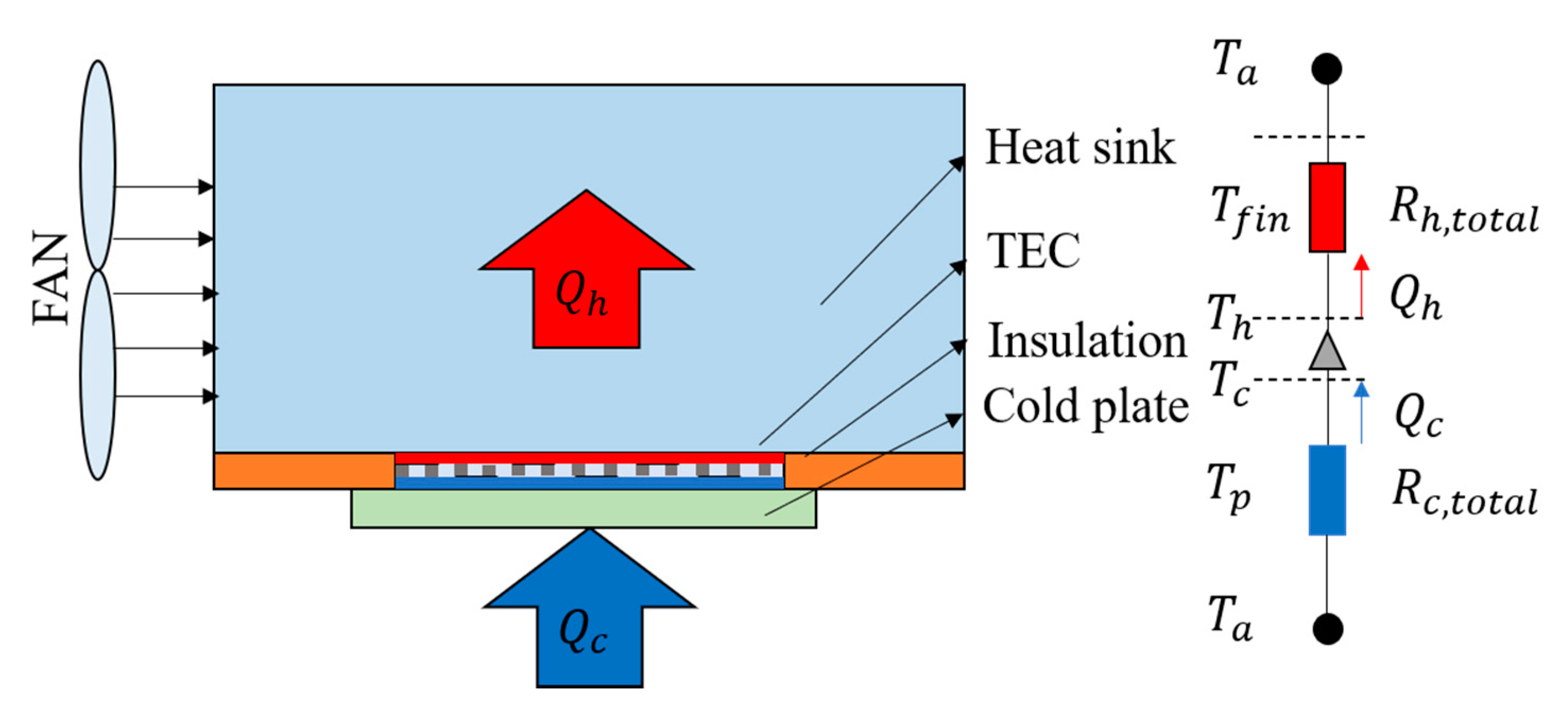
2.1. TEC Model

Figure 1 shows the schematic diagram of the thermoelectric refrigeration model and thermal resistance network diagram. It consists of a hot-end heat sink, thermoelectric module, insulation plate, and a cold plate. At the same time, to enhance the heat dissipation effect, the hot side is usually equipped with a fan.
As illustrated in Figure 1, Q h and Q c are the total heat and cooling capacity of the thermoelectric units, respectively, which may be calculated using Equations (1) and (2).
Q h = S m I t T h + 1 2 I t 2 R m K m ( T h T c )
Q c = S m I t T c 1 2 I t 2 R m K m ( T h T c )
All T h and T c values can be measured according to the experiment. I t is the current passing through the TEC module. In the equation, S m , R m and K m represent the Seebeck coefficient, electrical resistance and thermal conductivity of the TEC module, respectively, and these values are physical property parameters of the TEC module. According to the performance table (Table 1) of the thermoelectric module given by the merchant, it can be obtained by the following (Equations (3)–(5)) proposed by Zhang et al. [24].
S m = V t max T h 0
R m = ( T h 0 Δ T max ) V t max T h 0 I t max
K m = ( T h 0 Δ T max ) V t max I t max 2 T h 0 Δ T max
The TEC module works between the cold plate and the heat sink. The heat transfer model of a typical thermoelectric system can be discussed using the thermal resistance network model shown in Figure 1. The thermal resistance on both sides is simplified in the thermal resistance network diagram, which only includes the total hot side thermal resistance ( R h , t o t a l ) and cold side thermal resistance ( R c , t o t a l ). The thermoelectric cooling module is modeled by the one-dimensional steady-state method used in most previous literature. The total thermal resistance of a thermoelectric refrigeration device is the ratio of the heating capacity of the device to the temperature difference of its corresponding ambient temperature.
R h , t o t a l = ( T h T a ) Q h
COP is an important index for evaluating the refrigeration performance of thermoelectric refrigeration devices. COP is defined as the ratio of the total cooling capacity of the equipment to the total energy consumption.
COP = Q c P t
In Equation (7), Q c can be calculated according to Equation (2), and P t is the electrical power of TEC module. Therefore,
P t = Q h Q c = I t 2 R m + S m I t ( T h T c )
The power consumption of the fan is also an important performance indicator, P f is the electrical power of the fan.
P f = V f I f

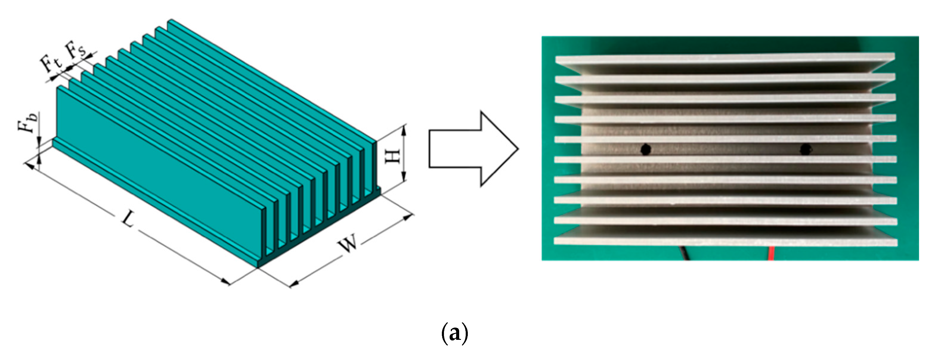
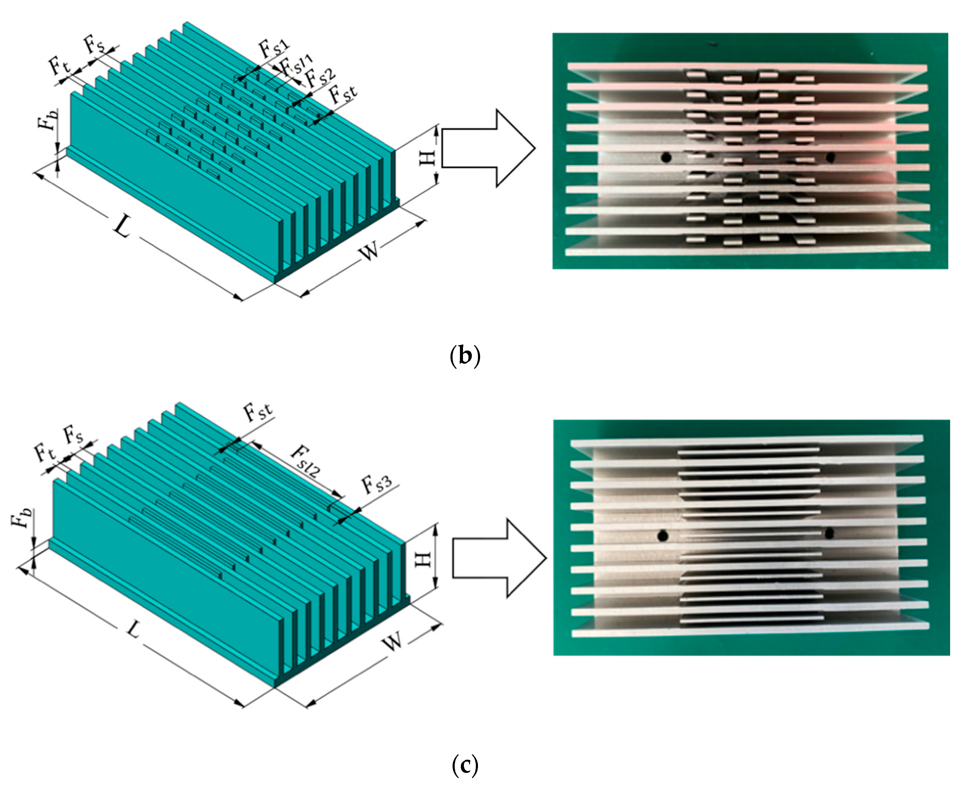
2.2. Heat Sink Model
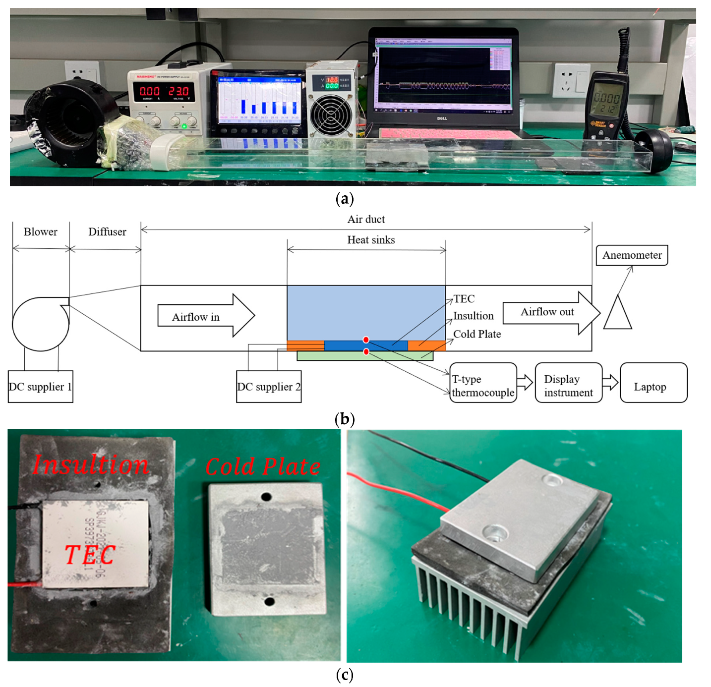
The finned heat sink is built of a thermally conductive aluminium alloy, and its overall size is 100 mm ( L ) × 60 mm ( W ) × 23 mm ( H ). At the same time, on the premise that the overall appearance size of the heat sink fin does not change, to increase the heat sink’s heat dissipation capacity, a sub-channel between the heat sink fin is added, that is, a new fin between the two fins (as shown in Figure 2b,c). The finned heat sink is manufactured by Beijing Terris Technology Co., Ltd. in China by wire-electrode cutting. Its goal is to increase the heat sink’s heat dissipation performance by extending the finned heat sink’s heat dissipation area and modifying the air-flow pattern.
The structural specifications of the finned heat sink are listed in Table 2. These parameters comprise fin thickness ( F t ), fin spacing ( F s ), fin base thickness ( F b ), sub-fin thickness ( F s t ), sub-fin length ( F s l 1 , F s l 2 ), sub-fin and fin spacing ( F s 1 , F s 2 , F s 3 ).

2.3. Experiments

To begin, a small test to compare three finned heat sinks was set up. The most important thing to do to test the performance of the new heat sink was to take a series of measurements and collect data under the same environmental conditions. The experimental platform included some TEC modules, fans, DC power supplies, air ducts, thermocouples and, most importantly, different hot-end heat sinks. The commercial TEC module used in this experiment is by Henan Guan jing Technology Company in China (product number HNGJ-085B). The size of TEC is 40 × 40 × 3.68 mm, and the number of crystal grains is 127 pairs. The specific product parameters are shown in Table 1.
The schematic structure of the test and the physical structure of the experiment are shown in Figure 3. The TEC module’s cold side is a cold conducting plate with threaded holes that primarily secures the TEC module. The TEC module’s hot side is an aluminium heat sink with a blower fan to inject air-fluid into the heat sink to lower the latter’s temperature. In the experiment, the temperature of the heat sink, the temperature of the TEC module’s cold surface, and the air temperature were all measured with T-type thermocouples and recorded by a display instrument (model SIN-R5000C). The speed and temperature of the incoming air were measured with an anemometer. Table 3 shows the accuracy of all the instruments. The wind speed of the blower fan can be changed by adjusting the voltage of the DC power supply 1. The power of the TEC module can also be changed by the DC power supply 2.
The TEC module used in the experiment was the same to limit the experimental error. At the same time, thermal grease must be applied equally between the TEC module, the heat sink, and the cold plate to reduce thermal resistance. On the other hand, as shown in Figure 3, the TEC module is surrounded by thermal insulation cotton to reduce heat loss. When installing the fixing screws, a torque wrench was used to ensure that the tightening force of each screw was 0.8. The temperature of the experimental environment was kept constant. The results of all tests are compared under the same conditions. Each group of experiments was repeated three times to ensure that the experimental results were accurate.

3. Results and Discussions

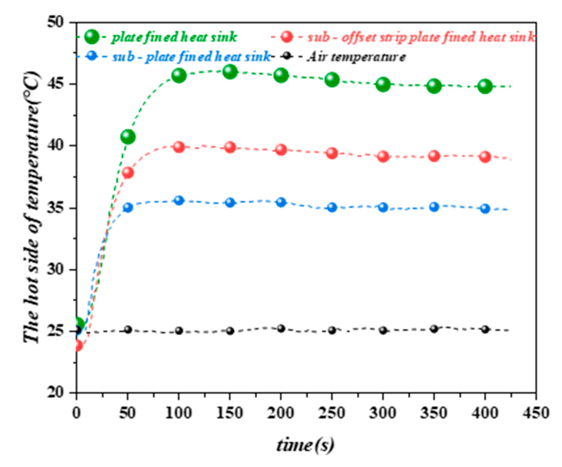
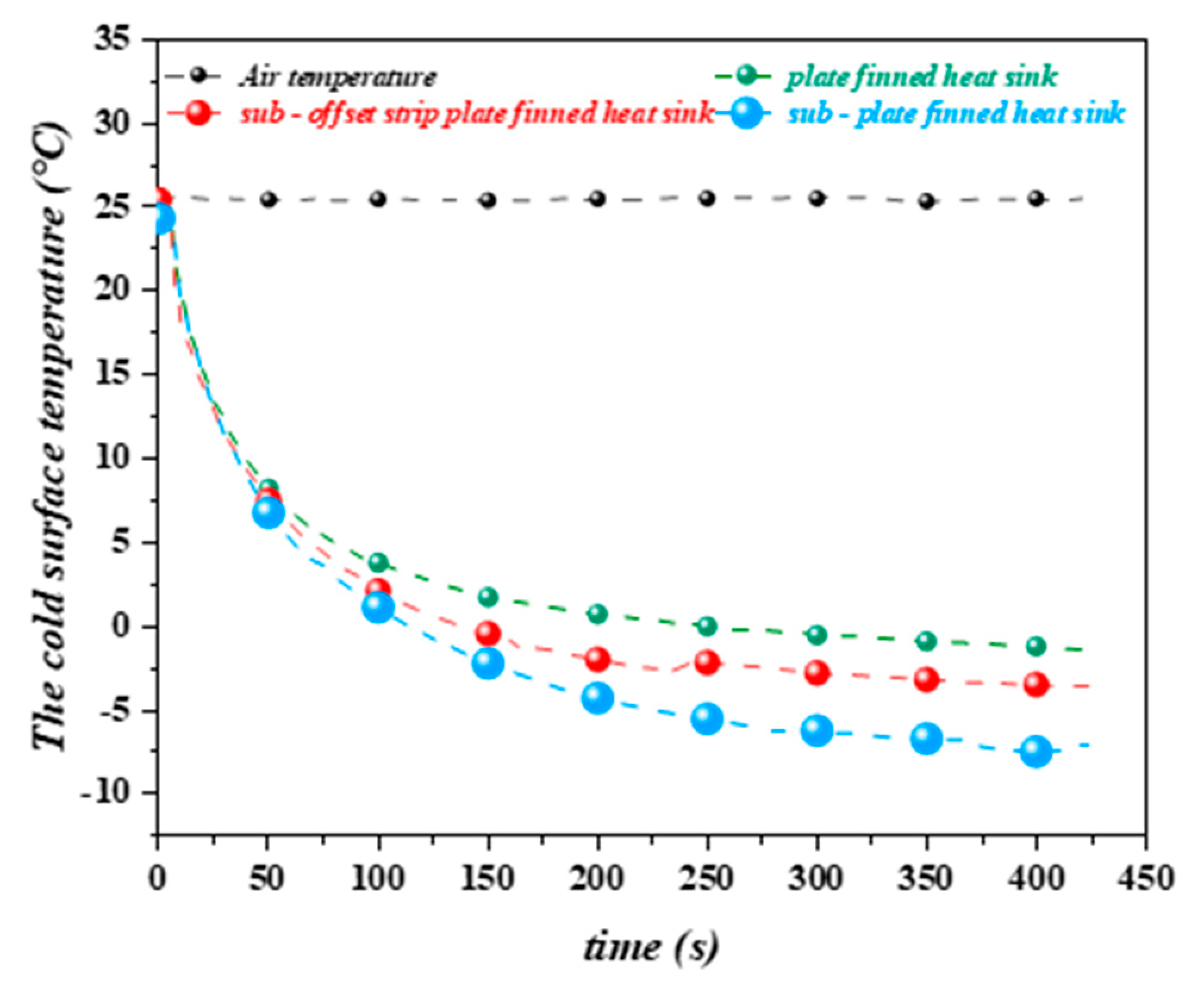
3.1. Basic Thermal Performance of Heat Sink Comparison

Two different improvement methods are proposed for the hot-end radiator of the thermoelectric cooling module. Figure 4 depicts the experimental outcomes. The results reveal that both heats sink effectively increase thermal performance under the same input current and wind speed. This phenomenon can be explained as when the heat sink on the hot side of the TEC module is constant, adding sub-channel fins is comparable to expanding the heat dissipation area of the heat sink, which enhances the heat exchange rate between solids and fluids. In addition, the formation of sub-channels can alter the temperature gradient between the fins. These effects all improve the thermal performance of the heat sink. Moreover, the sub-channel fins and the sub-channel offset fins change the flow state of the air, increase the turbulence of the air, and make the boundary layer periodically broken, thereby further enhancing the heat transfer capacity.
.

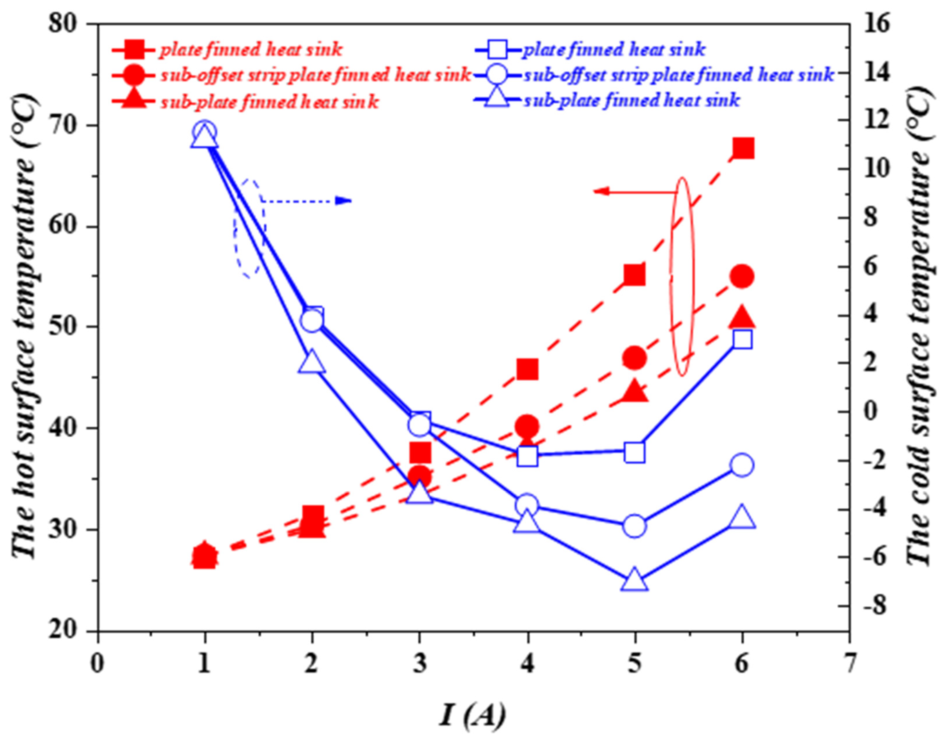
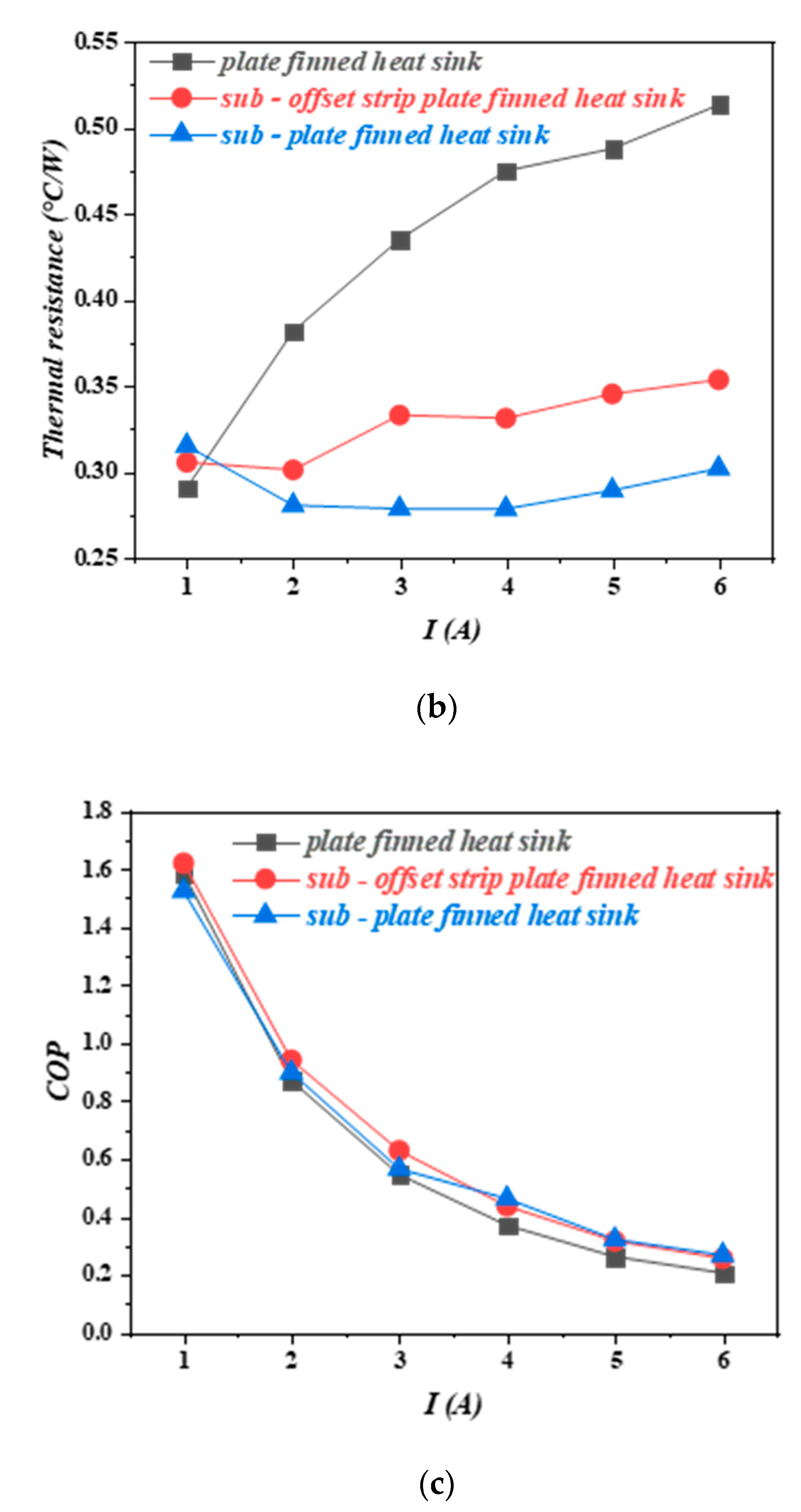
3.2. Thermal Performance under Different Current of Heat Sink Comparison

The temperature of the hot and cold surfaces of the TEC module changes with input current, as shown in Figure 5a. The following can be seen in the diagram, the hot surface temperature of the TEC module rises as the input current is increased. When the input current I = 1   A , the temperature of the hot surface is basically the same, due to the fact that all three types of heat sink effectively diffuse heat into the air. As the input current increases, the TEC module generates more heat, and the advantages and disadvantages of the three heat sinks are highlighted, which can be seen from the thermal surface diagram. When the current I = 5   A , the thermal surface temperature of the TEC module is reduced by about 15.1 % and 21.4 % , respectively, when the sub-offset strip plate finned heat sink and the sub-plate finned heat sink are compared to the plate finned heat sink.
The thermal resistance of the heat sink and the COP of the overall thermoelectric cooling module will change as the input current changes, in addition to the temperature of the TEC module’s hot and cold surfaces. As indicated in Figure 5b,c, at the same output wind speed, the thermal resistance rises gradually with the increasing current. This is because as the input current increases, a large amount of Joule heating effect will be generated inside the TEC device, and the heat is not exported in time, which leads to an enlargement in the temperature concerning the hot surface. While the external environment temperature does not change, according to Fourier’s first law, the total thermal resistance of the thermoelectric device increases. Nonetheless, the COP decreases as the input current increases, which has been proven in all research. The experimental results show that when the input current I = 5   A , the thermal resistance of the sub-offset strip plate finned heat sink and sub-plate finned heat sink is reduced by 29.2 % and 40.8 % , respectively, compared with that of plate finned heat sink. The thermal performance of the new heat sink is remarkable. It can be explained that the good heat dissipation capacity of the new fin keeps the temperature of the TEC module’s hot surface low. According to Fourier’s first law, we can get that the thermal resistance will inevitably be reduced. At the same time, the reduction of heat resistance of the heat sink will inevitably lead to the improvement of the refrigeration performance of the thermoelectric refrigeration unit. When the input current I = 4   A , the COP value of sub-offset strip plate finned heat sink and sub-plate finned heat sink increased by 15.0 % and 19.7 % , respectively, compared with that of the plate finned heat sink.

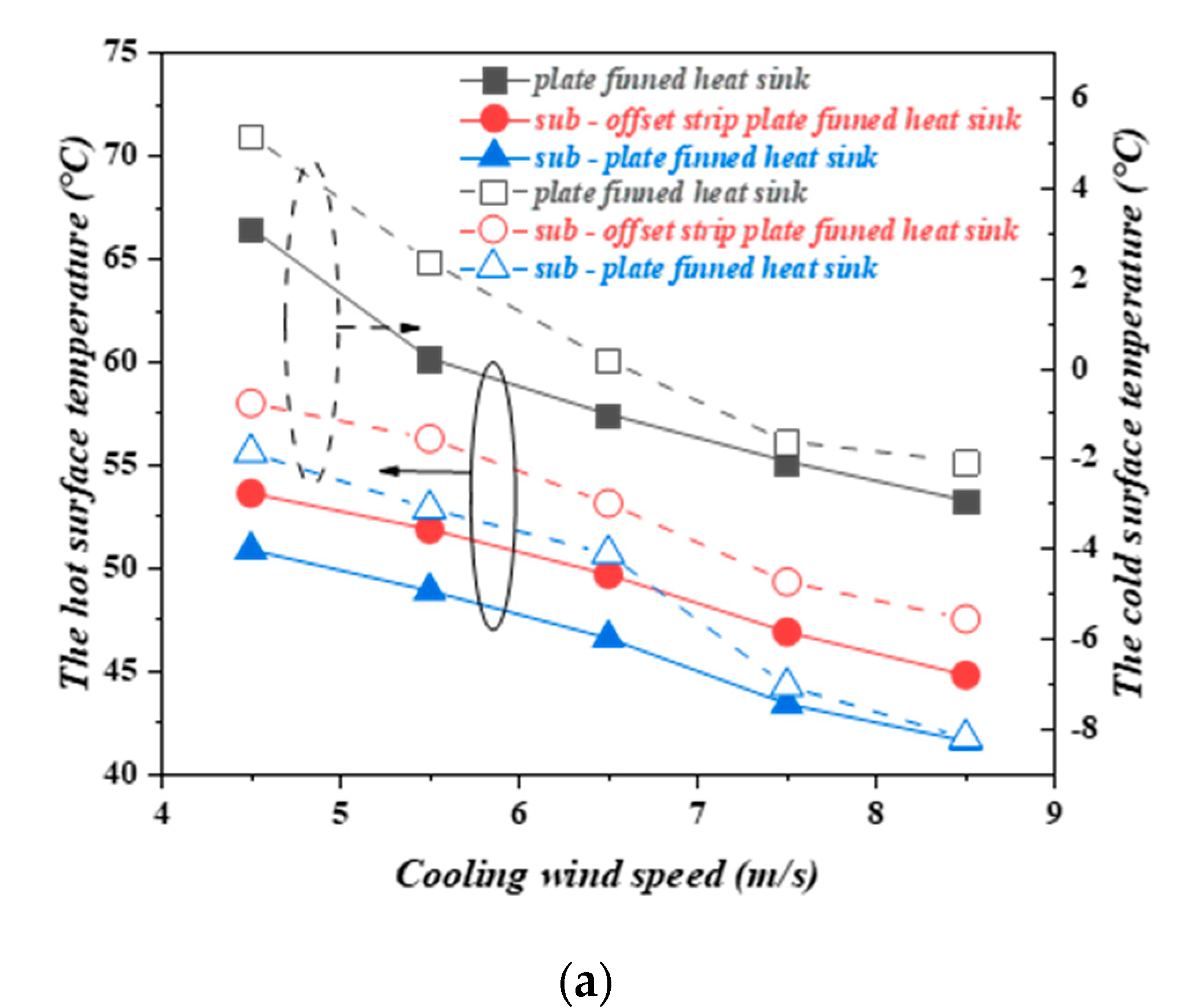
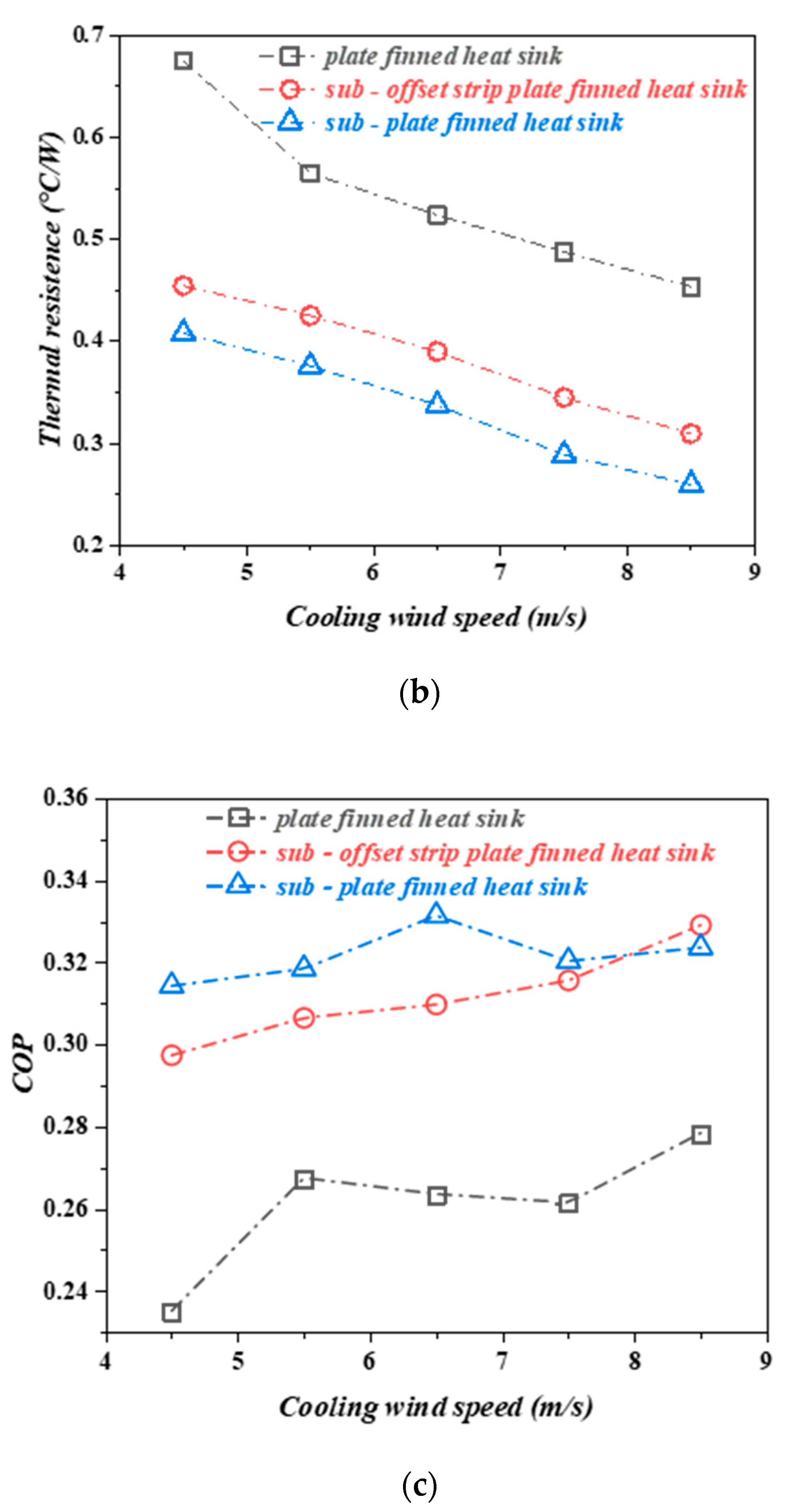
3.3. Thermal Performance under Different Wind Speed of Heat Sink Comparison

In this study, the influence of the cooling wind speed of the heat sink on the performance of the TEC module was also evaluated in detail. Under varying cooling wind speeds, the experimental findings of the TEC module’s hot and cold surface temperatures, total thermal resistance, and total COP are seen in Figure 6. The experimental results clearly show that increasing the TEC device’s cooling wind speed decreased the TEC module’s hot and cold surface temperatures, decreased the total thermal resistance, and enhanced the COP. In addition, we can obviously see from Figure 6a that the new heat sink still maintains superior thermal performance under different wind speeds. When the cooling wind speed is U = 6.5   m / s , the average cold surface temperature of the TEC device of sub-offset strip plate finned heat sink and sub-plate finned heat sink is reduced by 3.18 °C and 4.3 °C respectively, compared with the plate finned heat sink. When the cooling wind speed reaches 8.5   m / s , a thermoelectric refrigeration unit’s average cold side temperature using a sub-plate finned heat sink may reach −8.25 °C, which is 6.35 °C lower than the temperature of a plate finned heat sink. The findings demonstrate that the novel heat sink can maintain excellent thermal performance in both low and high wind speeds.
As shown in Figure 6b, the thermal resistance of the three types of heat sinks rapidly reduces as the cooling wind speed increases. This is because a higher cooling wind speed allows for more heat transfer between the air and the heat sink, resulting in a higher local convective heat transfer coefficient, improved heat transfer performance, and lower thermal resistance. Under the same cooling wind speed, the thermal resistance of the new heat sink is reduced by 24.7 % ~ 42.6 %   compared to the original heat sink. Figure 6c shows that a higher cooling wind speed might result in a higher COP value. This does not imply that the air-flow rate can be increased indefinitely to increase the thermoelectric device’s COP value. This occurs because the internal friction between the cooling air flowing through the fin and the fin absorbs the radiator’s heat dissipation capacity. If the cooling wind speed increases any further, the wind speed will reach a critical value, and the thermoelectric device’s COP value will stop increasing. As shown in Figure 6c, under the same cooling wind speed, the COP of the thermoelectric device under the new finned heat sink is 13.9 % ~ 20.5 %   higher than that under the ordinary finned heat sink. However, under different cooling wind speeds, the COP value of the thermoelectric device of the same heat sink will gradually increase. When it reaches a specific value (the cooling wind speed in this experiment is 6.5   m / s ), although the thermal resistance will still decrease, the COP value of the system changes very little.

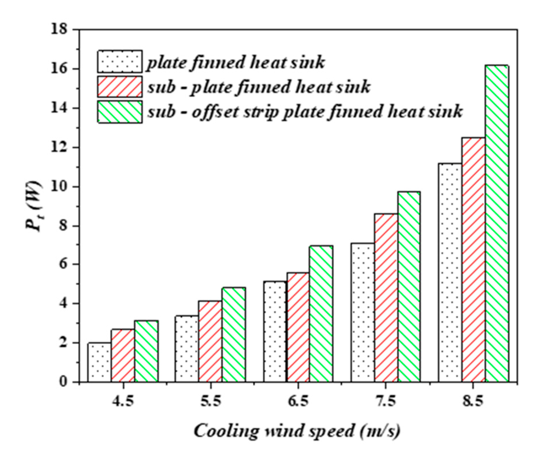
3.4. Additional Power of Thermoelectric Devices Comparison

Two new types of finned heat sinks are designed based on thermal optimization to enhance the cooling capacity of the thermoelectric refrigeration equipment. Experiments were conducted on three different types of finned heatsinks. It is impossible to overlook the fact that increasing the heat sink’s heat dissipation capacity will increase internal friction, which will lead to an increase in pressure drop. As a result, this additional power must be quantified to overcome the pressure drop caused by the heat sink change. Under the experimental conditions, the power required for the three heat sinks to reach the corresponding cooling wind speed is shown in Figure 7.
The power consumption of fans is also a very important parameter in thermoelectric refrigeration devices. The power required by the fan gradually increases as the cooling wind speed increases. The fan’s power consumption under the three heat sink types is significantly less when the cooling wind rate is meager. As the wind speed gradually increases, the power required by the fans in the thermoelectric units with sub-plate finned heat sink and sub-offset strip plate finned heat sink to achieve a cooling wind speed of   7.5   m / s   is increased by   11.4 %   and 26.7 % , respectively, compared to the plate finned heat sink. This is because, as the wind speed at the outlet increases, the boundary layer friction resistance of the air-fluid on the fin increases, resulting in the fan requiring greater input power to overcome the friction resistance. In fact, in order to achieve a cooling wind speed of 8.5   m / s , the power consumed by the fan under the sub-offset strip plate finned heat sink unit would be 166 %   of the power consumed at a cooling wind speed of   7.5   m / s . Although an increase in cooling wind speed reduces the heat sink’s thermal resistance by   10.2 % , the COP value of thermoelectric units has remained relatively unchanged, which has been explained above. Therefore, if it is not that the temperature of the cold side must reach a certain low temperature, the cooling wind speed of the hot side should not be too high, otherwise, the power consumed by the fan will increase sharply.

4. Conclusions

This paper mainly studies the performance of a new type of thermoelectric refrigeration unit with the finned heat sink. The impact of various input currents and cooling wind speeds on the cooling effect is investigated, as well as the power consumption of the auxiliary equipment. We reached the following conclusions.
  • The new finned heat sink has a stronger heat dissipation function than the conventional finned heat sink and its thermal resistance is reduced by 42.6%.
  • The thermoelectric refrigeration system using the new fin heat sink has a higher coefficient of refrigeration performance, and the COP of the thermoelectric refrigeration system under the new fin can be increased by 22.8%.
  • Cooling wind speed can further improve the refrigeration performance, and increasing the wind speed can make the lowest temperature of the refrigeration performance reach −8.25 °C.
  • The additional power consumed by the fan of the thermoelectric refrigeration system under the new finned radiator can be up to 166% compared with the conventional refrigeration device.

Author Contributions

Conceptualization, X.S.; experimental investigation, G.X.; validation, J.Z.; resources, H.Y. and B.F.; data curation, G.X.; writing—original draft preparation, G.X.; writing—review and editing, X.S.; visualization, Q.Z.; supervision, J.Z.; project administration, H.Z. All authors have read and agreed to the published version of the manuscript.

Funding

This study was funded by Zhongyuan Science and Technology Innovation Leadership Program of China (Grant No. 214200510014).

Institutional Review Board Statement

Not applicable.

Informed Consent Statement

Not applicable.

Data Availability Statement

There was no data.

Conflicts of Interest

The authors declare no conflict of interest.

Abbreviations

COPcoefficient of performance
F b fin base thickness, mm
F s fin spacing, mm
F s 1 sub-fin and fin spacing 1, mm
F s 2 sub-fin and fin spacing 2, mm
F s 3 sub-fin and fin spacing 3, mm
F s t sub-fin thickness, mm
F s l 1 sub-fin length 1, mm
F s l 2 sub-fin length 2, mm
F t fin thickness, mm
H height of heat sink, mm
I electrical current, A
L length of heat sink, mm
P t TEC input electrical power, W
P f FAN input electrical power, W
Q c cooling capacity of TEC, W
Q h heat generation of TEC, W
R thermal resistance, ◦C/W
R m electrical resistance of TEC, Ω
K m thermal conductivity of TEC, W/m K
S m Seebeck coefficient of TEC, V/K
T temperature, °C
T a ambient temperature, °C
T c TEC module cold side temperature, °C
T h 0 TEC hot side temperature in supplier’s datasheet, °C
T p plate temperature, °C
T h TEC module hot side temperature, °C
T E C thermoelectric cooler
U cooling wind speed, m/s
V voltage, V
W width of heat sink, mm
Greece symbols
T m a x maximum temperature difference between hot and cold ends of TEC module, °C
Subscripts
a ambient
c cold side
f fan
h hot side
m a x maximum
p plate
t tec

References

  1. Choudhary, V.; Kumar, M.; Patil, A.K. Experimental investigation of enhanced performance of pin fin heat sink with wings. Appl. Therm. Eng. 2019, 155, 546–562. [Google Scholar] [CrossRef]
  2. Goswami, R.; Das, R. Waste heat recovery from a biomass heat engine for thermoelectric power generation using two-phase thermosyphons. Renew. Energy 2020, 148, 1280–1291. [Google Scholar] [CrossRef]
  3. Sharma, S.; Dwivedi, V.K.; Pandit, S.N. A review of thermoelectric devices for cooling applications. Int. J. Green Energy 2014, 11, 899–909. [Google Scholar] [CrossRef]
  4. Huang, Y.X.; Wang, X.D.; Cheng, C.H.; Lin, D.T.W. Geometry optimization of thermoelectric coolers using simplified conjugate-gradient method. Energy 2013, 59, 689–697. [Google Scholar] [CrossRef]
  5. Fabián-Mijangos, A.; Min, G.; Alvarez-Quintana, J. Enhanced performance thermoelectric module having asymmetrical legs. Energy Convers. Manag. 2017, 148, 1372–1381. [Google Scholar] [CrossRef]
  6. Dongxu, J.; Zhongbao, W.; Pou, J.; Mazzoni, S.; Rajoo, S.; Romagnoli, A. Geometry optimization of thermoelectric modules: Simulation and experimental study. Energy Convers. Manag. 2019, 195, 236–243. [Google Scholar] [CrossRef]
  7. Lu, X.; Zhao, D.; Ma, T.; Wang, Q.; Fan, J.; Yang, R. Thermal resistance matching for thermoelectric cooling systems. Energy Convers. Manag. 2018, 169, 186–193. [Google Scholar] [CrossRef]
  8. He, Y.; Cao, C.; Wu, J.; Chen, G. Investigations on coupling between performance and external operational conditons for a simiconductor refrigeration system. Int. J. Refrig. 2020, 109, 172–179. [Google Scholar] [CrossRef]
  9. Elghool, A.; Basrawi, F.; Ibrahim, T.K.; Habib, K.; Ibrahim, H.; Idris, D.M.N.D. A review on heat sink for thermo-electric power generation: Classifications and parameters affecting performance. Energy Convers. Manag. 2017, 134, 260–277. [Google Scholar] [CrossRef]
  10. Liu, Y.; Su, Y. Experimental investigations on COPs of thermoelectric module frosting systems with various hot side cooling methods. Appl. Therm. Eng. 2018, 144, 747–756. [Google Scholar] [CrossRef]
  11. Riffat, S.B.; Qiu, G.Q. Design and characterization of a cylindrical, water-cooled heat sink for thermoelectric air-conditioners. Int. J. Energy Res. 2006, 30, 67–80. [Google Scholar] [CrossRef]
  12. Astrain, D.; Vián, J.G.; Domínguez, M. Increase of COP in the thermoelectric refrigeration by the optimization of heat dissipation. Appl. Therm. Eng. 2003, 23, 2183–2200. [Google Scholar] [CrossRef] [Green Version]
  13. Astrain, D.; Vián, J.G. Study and optimization of the heat dissipater of a thermoelectric refrigerator. J. Enhanc. Heat Transf. 2005, 12, 159–170. [Google Scholar] [CrossRef]
  14. Karwa, N.; Stanley, C.; Intwala, H.; Rosengarten, G. Development of a low thermal resistance water jet cooled heat sink for thermoelectric refrigerators. Appl. Therm. Eng. 2017, 111, 1596–1602. [Google Scholar] [CrossRef]
  15. Cuce, E.; Guclu, T.; Cuce, P.M. Improving thermal performance of thermoelectric coolers (TECs) through a nanofluid driven water to air heat exchanger design: An experimental research. Energy Convers. Manag. 2020, 214, 112893. [Google Scholar] [CrossRef]
  16. Kim, D.K.; Kim, S.J.; Bae, J.K. Comparison of thermal performances of plate-fin and pin-fin heat sinks subject to an impinging flow. Int. J. Heat Mass Transf. 2009, 52, 3510–3517. [Google Scholar] [CrossRef]
  17. Izci, T.; Koz, M.; Koşar, A. The effect of micro pin-fin shape on thermal and hydraulic performance of micro pin-fin heat sinks. Heat Transf. Eng. 2015, 36, 1447–1457. [Google Scholar] [CrossRef]
  18. Wiriyasart, S.; Naphon, P. Heat spreading of liquid jet impingement cooling of cold plate heat sink with different fin shapes. Case Stud. Therm. Eng. 2020, 20, 100638. [Google Scholar] [CrossRef]
  19. Rao, A.K.; Somkuwar, V. Heat transfer of a tapered fin heat sink under natural convection. Mater. Today Proc. 2021, 46, 7886–7891. [Google Scholar] [CrossRef]
  20. Lee, G.; Lee, I.; Kim, S.J. Topology optimization of a heat sink with an axially uniform cross-section cooled by forced convection. Int. J. Heat Mass Transf. 2020, 168, 120732. [Google Scholar] [CrossRef]
  21. Abbas, A.; Wang, C.C. Augmentation of natural convection heat sink via using displacement design. Int. J. Heat Mass Transf. 2020, 154, 119757. [Google Scholar] [CrossRef]
  22. Leong, K.C.; Li, H.Y.; Jin, L.W.; Chai, J.C. Numerical and experimental study of forced convection in graphite foams of different configurations. Appl. Therm. Eng. 2010, 30, 520–532. [Google Scholar] [CrossRef]
  23. Hong, F.; Cheng, P. Three dimensional numerical analyses and optimization of offset strip-fin microchannel heat sinks. Int. Commun. Heat Mass Transf. 2009, 36, 651–656. [Google Scholar] [CrossRef]
  24. Zhang, H.Y.; Mui, Y.C.; Tarin, M. Analysis of thermoelectric cooler performance for high power electronic packages. Appl. Therm. Eng. 2010, 30, 561–568. [Google Scholar] [CrossRef]
Figure 1. Schematic diagram of thermoelectric refrigeration model and thermal resistance network diagram.
Energies 15 00145 g001
Figure 2. Dimensions and physical drawings of three types of finned heat sinks; (a) plate finned heat sink; (b) sub-offset strip plate finned heat sink; (c) sub-plate finned heat sink.
Energies 15 00145 g002aEnergies 15 00145 g002b
Figure 3. The experimental figure. (a) The physical structure of the experiment, (b) the schematic structure of the test, (c) physical picture of thermoelectric refrigeration module.
Energies 15 00145 g003
Figure 4. Temperature diagram of hot and cold surface of TEC module under three kinds of heat sinks ( I = 5   A , U = 7.5   m / s ) .
Energies 15 00145 g004aEnergies 15 00145 g004b
Figure 5. Comparison of heat sink performance under different input current, (a) the hot and cold surface temperature, (b) thermal resistance of hot side, (c) COP. ( U o u t = 7.5   m / s ).
Energies 15 00145 g005aEnergies 15 00145 g005b
Figure 6. Comparison of heat sink performance under different cooling wind speed, (a) the hot and cold surface temperature, (b) thermal resistance of hot side, (c) COP. ( I = 5   A ).
Energies 15 00145 g006aEnergies 15 00145 g006b
Figure 7. Fan power at different cooling speeds.
Energies 15 00145 g007
Table 1. Properties of the TEC module.
Parameters T h 0 I max V max Δ T max Q max
Units°CAV°CW
Values277.613.970.562.6
Table 2. Structural parameters of heat sink.
Parameter F t F s F b F s t F s l 1 F s l 2 F s 1 F s 2 F s 3
Unitmm
Values2431540211.5
Table 3. Measuring devices and their characteristics.
NameTypeAccuracyResolution
DC supplier 1MS-3010D≤0.1%0.01 A
DC supplier 2HYX-1200E30≤0.1%0.1 A
AnemometerAC826±3%0.001 m/s
ThermocoupleT0.1 °C0.01 °C
Display instrumentSIN-R5000C0.2%0.01 °C
Publisher’s Note: MDPI stays neutral with regard to jurisdictional claims in published maps and institutional affiliations.

