Article

Frequency Analysis of Partial Short-Circuit Fault in BLDC Motors with Combined Star-Delta Winding †

The Faculty of Electrical and Computer Engineering, Rzeszow University of Technology, Al. Powstancow Warszawy 12, 35-959 Rzeszow, Poland
*
Author to whom correspondence should be addressed.
The article was presented during 16th International Conference Selected Issues of Electrical Engineering and Electronics WZEE 2021 (Rzeszow September 2021).
Energies 2022, 15(1), 196; https://doi.org/10.3390/en15010196
Submission received: 18 November 2021 / Revised: 20 December 2021 / Accepted: 24 December 2021 / Published: 28 December 2021

Abstract

:
This paper analyses the condition of a partial short-circuit in a brushless permanent magnet motor. Additionally, the problem was analysed for three stator winding configurations: star, delta and star-delta connection. The paper presents an original mathematical model allowing a winding configurations to be analysed. What is more, the said mathematical model allows taking account of the partial short-circuit condition. Frequency analysis (Fast Fourier Transform—FFT) of the artificial neutral point voltage was proposed for the purpose of detecting the partial short-circuit condition. It was demonstrated that a partial short-circuit causes a marked increase in the diagnostic frequencies of the voltage signal. The proposed brushless permanent magnet motor diagnostic method is able to detect the fault regardless of the stator winding configuration type.

1. Introduction

Brushless permanent magnet motors are an attractive alternative to typical induction motors [1,2,3,4,5]. The use of high-energy permanent magnets enables the reduction of the weight of the motor while keeping the power of the motor at the same level. At the same time, the energy conversion efficiency is higher than in the case of induction motors [6,7,8,9]. As it is necessary to use a power-electronic system, brushless permanent magnet motors can be used effectively predominantly in drives with variable rotational speed. In some cases, due to the limitations in terms of the available space and the weight of the driving unit, permanent motors are the only alternative [10,11]. Electric equipment of this type is successfully used in the drives intended for small unmanned aerial vehicles (UAVs) [12]. The basic characteristics of such equipment should include reliability, which means that it is necessary to monitor their operation and prevent possible failures.
Causes of a failure of a drive system featuring a permanent motor may occur in the power supply system (extrinsic causes) or in the equipment itself (intrinsic causes). Intrinsic causes include all sorts of open-circuits or short-circuits in the winding of the motor, e.g., partial short-circuits in the winding [12,13,14,15,16,17,18,19]. The consequences of a partial short-circuit depend, inter alia, on the number of shorted turns. The fault current and phase current are in opposite phase. The fault current generates reverse magnetic flux in the faulty slot, which opposes the main flux. This causes a change in the value of the flux in each pole of the faulty phase. A greater number of shorted turns has a severely negative effect on the performance of the motor. In most cases, it impedes further operation of the drive system. In the case of the so-called critical drives, their operation is monitored. There are various methods for monitoring and diagnosing the operation of electric motors [20,21,22,23]. Electric, temperature or vibration signals are used for monitoring and diagnostic purposes. As far as electric signals are concerned, it is very often the case that, e.g., in the case of induction motors, the motor currents are used as diagnostic signals [24]. These are effective tools for detecting, e.g., rotor damage [25]. Detection of a partial short-circuit in brushless permanent motors is a much more complex problem. Machine Current Signature Analysis (MCSA) is used to detect inter-turn short circuit [17]. In this case, different signal processing techniques can be applied, e.g., Hilber-Huang (HHt), wavelet transform (WT) or fast Fourier transform (FFT). In general, the method extracts current harmonics. Depending on the technique, for example, the 3rd harmonic or the 9th harmonic are significant. The appearance of these harmonics usually indicates an internal short-circuit condition. A typical disadvantage of the method is the dependence of the diagnostic signals on the operating point of the machine (speed, torque).
The voltage approach to the detection of partial short-circuit conditions is almost independent of the load torque. Additionally, in this case, there are various fault detection techniques based on the voltage analysis, e.g., zero-sequence-voltage components (ZSVC), voltage asymmetry, Park vector, wavelet transform [17]. The most popular is ZSVC [21,23]. It is reliable and can detect single short-circuit. Nevertheless, it can be applied only for star connection and requires access to the winding neutral point.
An artificial neutral point is used in senseless control systems. Such control method does not require connection to the winding neutral point. The rotor position is calculated on the basis of BEMF third-harmonic analysis. An artificial neutral point voltage also can be used for the purpose of detecting various fault conditions of a BLDC motor. The authors of this paper have successfully applied this method to detect a typical fault condition, i.e., an open-circuit in one of the windings of a BLDC motor [26]. The same method can be also applied to detect a partial short-circuit, as described herein.
This article presents an analysis of various partial-short-circuit conditions of a BLDC motor that is type of PMM used as a component of a hybrid drive system of an unmanned aerial vehicle (UAV). To demonstrate the universal nature of the method, partial short-circuit conditions were analysed for three stator winding configurations, i.e., star (Y), delta (Δ) and, as a new addition, star-delta (YΔ) configuration. The paper includes an original mathematical model of a BLDC motor allowing for the partial short-circuit condition in the selected phase for the star-delta (YΔ) winding configuration. The paper analyses symmetrical operation as well as the performance of the drive system in the selected fault condition, i.e., a partial short-circuit, in one of the phases of the stator winding of the BLDC motor for star, delta as well as star-delta winding configuration. Fast Fourier Transform (FFT) of the voltage signal in the form of the voltage of the so-called artificial neutral point, a method which can be used regardless of the motor winding configuration type, was used for the purpose of monitoring the performance of the drive system featuring a BLDC motor. Selected results of simulations and laboratory tests were presented, particularly of line currents, the content of higher harmonics of the voltage of the artificial neutral point as well as thermal tests for the symmetrical operation and for the analysed short-circuit conditions. The conclusions section demonstrates the usefulness of the proposed methods for diagnosing fault conditions in the form of a partial short-circuit in BLDC motors.
The machine diagnostics is especially important in the critical drives where high reliability is required. This can be achieved by using, for example, a multi-channel power supply. According to the authors, each channel can be considered as an independent machine. Information about the status of each channel is crucial for the operation of the critical drive. The proposed method based on FFT analysis of the artificial neutral point voltage is, in the authors’ opinion, suitable for multi-channel power supply.

2. Analysis of the Winding Configuration

2.1. Star, Delta and Star-Delta Windings Configuration

Typical configurations of the windings of brushless permanent motors are star connection and, much less commonly, delta connection. Delta connection is successfully used in low-voltage, low-power motors. A mixed star-delta connection is an unusual configuration. At this point, there are very few papers on this non-standard winding configuration type [27,28]. This applies particularly to brushless permanent motors [29].
Figure 1 presents a hybrid drive system featuring a brushless DC motor to be used in an unmanned aerial vehicle (UAV). Selected motor parameters are listed in Table 1.
Reconfiguration of the motor windings was taken into account at their design stage. Apart from the typical star or delta configurations, it is also possible to use the mixed star-delta connection type. All of the analysed configurations were illustrated in Figure 2b–d.
Figure 2a presents the system for the detection of the voltage of the artificial neutral point u0. The system for the detection of the voltage of the artificial neutral point u0 is independent of the winding configuration (Figure 2a).
In the analysed winding configurations, shorted turns were highlighted. A partial short-circuit in the star configuration was labelled as SC1. Similarly, in the case of a mixed star-delta configuration, a short-circuit in the star section was also labelled as SC1. A short-circuit for the delta connection or in the delta section (of a mixed, star-delta connection) was labelled as SC2.

2.2. Static Characteristics

Static characteristics in the symmetry conditions and in the partial short-circuit condition were identified based on the numerical models. The star winding configuration was assumed to the basic variant (Figure 2b). In the case of windings with a star connection, the current value IY = 10 A was used for the tests. This corresponds to current density of 8 A/mm2. Current values for the remaining configurations were recalculated allowing for maintaining identical copper loss values [30].
In the case of delta type or the mixed-type connection (fault in the delta section), in static conditions it is necessary to perform calculations/measurements in the situation of a short-circuit of the so-called short (Figure 2c Δ, Figure 2d YΔ I1 = −I3, I2 = 0) and long (Figure 2c Δ, Figure 2d YΔ I1 = −I2, I3 = 0) path.
Figure 3 presents the results of the calculations for the analysed winding configurations.
Table 2 presents torque constants (kT = Teav/Irms) corresponding to particular configurations and the partial short-circuit condition.

2.3. Induced Voltage

In the case of the line induced voltage (BEMF), identical tests were performed at 1000 rpm. Figure 4 presents the results of the calculations.
Table 3 presents voltage constants (KE) corresponding to particular configurations as well as the partial short-circuit condition.

3. Mathematical Model of the Stator Short-Circuit in BLDC Motor with Star-Delta Winding

The mathematical model of a BLDC are presented for BLDC machines with YΔ winding configurations. The following simplifying assumptions are adopted in proposed model of the three-phase BLDC motor:
-
symmetric cylindrical stator and permanent magnet type rotor, linear magnetic circuit, cogging and reluctance torques are neglected,
-
short-circuit of the Y winding coils in phase 1 (YΔ configuration) with current i 1 Ysc and BEMF voltage e 1 Ysc , respectively,
-
the short-circuit parameters are referred as R 1 Ysc -resistance, L 1 Ysc -inductance.
Final equations of the model are derived from the base equations without constraints and constraint equations resulting from the YΔ stator winding configuration of the BLDC motor.

3.1. No-Constraints Phase Voltages, Three-Phase BLDC Star-Delta Model

The general structure of the mathematical model of the three-phase BLDC motor with combined YΔ windings can be written in the following form:
u Y u Δ 0 = R Y 0 0 0 R Δ 0 0 0 R 1 Ysc i Y i Δ i 1 Ysc + L YY L Y Δ L Ysc L Δ Y L Δ Δ L Δ sc L scY L sc Δ L 1 Ysc d d t i Y i Δ i 1 Ysc + e Y e Δ e 1 Ysc
J d ω m d t + D ω m + T L = T e
where total electromagnetic torque T e is given by:
T e = 1 ω m i Y T e Y + i Δ T e Δ + i 1 Ysc e 1 Ysc
In Equations (1)–(3) vectors representing phase voltages u Y , u Δ , phase currents i Y , i Δ , phase BEMF voltages e Y , e Δ , as well as matrices of stator resistances R Y , R Δ and coefficients of self- and mutual inductances L YY , L Δ Δ , L Y Δ , L Δ Y , L Ysc , L Δ sc , L scY , L sc Δ are defined as follows:
u Y = u 1 Y , u 2 Y , u 3 Y T ; i Y = i 1 Y , i 2 Y , i 3 Y T ; e Y = e 1 Y , e 2 Y , e 3 Y T ; R Y = diag ( R 1 Y , R 2 Y , R 3 Y )
u Δ = u 1 Δ , u 2 Δ , u 3 Δ T ; i Δ = i 1 Δ , i 2 Δ , i 3 Δ T ; e Δ = e 1 Δ , e 2 Δ , e 3 Δ T ; R Δ = diag ( R 1 Δ , R 2 Δ , R 3 Δ )
L YY = L 1 Y 1 Y L 1 Y 2 Y L 1 Y 3 Y L 2 Y 1 Y L 2 Y 2 Y L 2 Y 3 Y L 3 Y 1 Y L 3 Y 2 Y L 3 Y 3 Y ;   L Y Δ = L 1 Y 1 Δ L 1 Y 2 Δ L 1 Y 3 Δ L 2 Y 1 Δ L 2 Y 2 Δ L 2 Y 3 Δ L 3 Y 1 Δ L 3 Y 2 Δ L 3 Y 3 Δ ;   L Ysc = L 1 Y 1 Ysc L 2 Y 1 Ysc L 3 Y 1 Ysc ;   L Δ Y = ( L Y Δ ) T ;  
L Δ Δ = L 1 Δ 1 Δ L 1 Δ 2 Δ L 1 Δ 3 Δ L 2 Δ 1 Δ L 2 Δ 2 Δ L 2 Δ 3 Δ L 3 Δ 1 Δ L 3 Δ 2 Δ L 3 Δ 3 Δ ;   L Δ sc = L 1 Δ 1 Ysc L 2 Δ 1 Ysc L 3 Δ 1 Ysc ;   L scY = ( L Ysc ) T ;   L sc Δ = ( L Δ sc ) T
The following symbols are used in Equations (1)–(3) for i, j = 1,2,3: u iY , u i Δ —phase voltages, i iY , i i Δ —phase currents, R iY , R i Δ —phase resistances, L iYjY , L iYj Δ , L i Δ j Δ , L iY 1 Ysc , L i Δ 1 Ysc -self and mutual inductances, e iY , e i Δ —phase back-EMFs voltages, R 1 Ysc , L 1 Ysc —resistance and inductance of short-circuit, J—rotor moment of inertia, ω m —mechanical angular speed of rotor, D—rotor damping of viscous friction coefficient, T L —load torque.
The phase BEMF voltage vectors e Y , e Δ and voltage e 1 Ysc in Equations (1) and (3) are defined as follows:
e Y = e 1 Y e 2 Y e 3 Y = ω K E 1 Y f Y θ K EY f Y θ 2 π 3 K EY f Y θ 4 π 3 ;   e Δ = e 1 Δ e 2 Δ e 3 Δ = ω K E Δ f Δ θ f Δ θ 2 π 3 f Δ θ 4 π 3 ; e 1 Ysc = ω K E 1 Ysc f Y θ
where θ—electrical rotor angle, ω = d θ / d t = p ω m —electrical angular speed, p—machine pole pairs, K E 1 Y , K EY , K E Δ , K E 1 Ysc —back-EMF constant of one phase and short-circuit, f Y ( θ ) , f Δ ( θ ) —phase trapezoidal functions, profile back-EMF. The permanent magnet flux linking each stator winding of the BLDC motor follows the trapezoidal profile back-EMF. The real phase BEMF is not a flat and ideal trapezoidal waveform and functions f Y ( θ ) , f Δ ( θ ) can be expressed as Fourier series.
Additional constraints on voltages and currents are imposed by the arrangement of motor phase windings in combined star-delta (YΔ) configuration. The relationship of line-to-line and phase voltages, line and phase currents in a Star-Delta (YΔ) connection, for example, can be written as:
u 12 u 23 u 31 = K Y u Y + u Δ ;   K Y = 1 1 0 0 1 1 1 0 1 ; i 1 i 2 i 3 = i 1 Y i 2 Y i 3 Y = K Δ i 1 Δ i 2 Δ i 3 Δ ; K Δ = 1 0 1 1 1 0 0 1 1
Including the constraint Equation (5) in (1) and (3), the final equations of the BLDC motor model can be written for YΔ configurations.

3.2. Final Star-Delta Winding Configuration Line Voltage Model

The model line-to-line voltages and total electromagnetic torques can be written as follows:
u 12 u 23 u 31 0 = R 11 R 12 R 13 0 R 21 R 22 R 23 0 R 31 R 32 R 33 0 0 0 0 R 1 Ysc i 1 Δ i 2 Δ i 3 Δ i 1 Ysc + L 11 L 12 L 13 L 1 sc L 21 L 22 L 23 L 2 sc L 31 L 32 L 33 L 3 sc L sc 1 L sc 2 L sc 3 L 1 Ysc d d t i 1 Δ i 2 Δ i 3 Δ i 1 Ysc + e 12 e 23 e 31 e 1 Ysc
T e = 1 ω m i 1 Δ e 12 + i 2 Δ e 23 + i 3 Δ e 31 + i 1 Ysc e 1 Ysc
The line-to-line back-EMF voltages in Equations (6) and (7) are defined as follows:
e 12 e 23 e 31 = e 1 Δ + e 1 Y e 2 Y e 2 Δ + e 2 Y e 3 Y e 3 Δ + e 3 Y e 1 Y
The equivalent motor parameters in Equation (6) are determined by the following relationships:
R 11 R 12 R 13 R 21 R 22 R 23 R 31 R 32 R 33 = K Y R Y K Δ + R Δ ; L 11 L 12 L 13 L 21 L 22 L 23 L 31 L 32 L 33 = K Y L YY K Δ + L Δ Y K Δ + K Y L Y Δ + L Δ Δ ;
L 1 sc L 2 sc L 3 sc = K Y L Ysc + L Δ sc ;   L sc 1 L sc 2 L sc 3 = L 1 sc L 2 sc L 3 sc T
Line currents of the star-delta (YΔ) winding configuration are calculated based on the phase currents i 1 Δ , i 2 Δ , i 3 Δ of the Δ section calculated based on the Equations (6) and (7) in line with the relation (5).
Equations (6) and (2) with (7) constitute in general a mathematical model of the stator short-circuit fault BLDC Motor with YΔ winding configurations. The equations will feature a similar structure in the event a short-circuit occurs, e.g., in the first phase of the Δ section of the YΔ winding configuration.
The equations allowing for a short-circuit in a winding connected exclusively in the Y or the Δ configuration represent special cases among the presented Equations (6) and (7). For example, the equations for the Y only connection will have the following form:
u 12 u 23 u 31 0 = R 11 R 12 R 13 0 R 21 R 22 R 23 0 R 31 R 32 R 33 0 0 0 0 R 1 Ysc i 1 Y i 2 Y i 3 Y i 1 Ysc + L 11 L 12 L 13 L 1 sc L 21 L 22 L 23 L 2 sc L 31 L 32 L 33 L 3 sc L sc 1 L sc 2 L sc 3 L 1 Ysc d d t i 1 Y i 2 Y i 3 Y i 1 Ysc + e 12 e 23 e 31 e 1 Ysc
T e = 1 ω m i 1 Y e 12 + i 2 Y e 23 + i 3 Y e 31 + i 1 Ysc e 1 Ysc
The line-to-line back-EMF voltages in Equations (11) and (12) are defined as follows:
e 12 e 23 e 31 = e 1 Y e 2 Y e 2 Y e 3 Y e 3 Y e 1 Y
The motor parameters in Equation (11) are determined by the following relationships:
R 11 R 12 R 13 R 21 R 22 R 23 R 31 R 32 R 33 = K Y R Y ;   L 11 L 12 L 13 L 21 L 22 L 23 L 31 L 32 L 33 = K Y L YY ;   L 1 sc L 2 sc L 3 sc = K Y L Ysc ;   L sc 1 L sc 2 L sc 3 = L 1 sc L 2 sc L 3 sc T
The elimination of the equation of the shorted circuit of the given winding from Equations (11) and (12) along with the adjustment of the value of equation coefficients allows obtaining equations for the special case, i.e., a Y configuration without a partial short-circuit in the first phase.

4. Discussion Comparative Analysis, Simulations and Experimental Verifications

All numerical and laboratory tests were conducted in the steady state at 500 rpm. The supply voltage was modified according to the voltage constants KE of particular configurations (Table 3). In the case of laboratory tests, the value of the load torque was modified in order to obtain the required operating point (500 rpm). For the analysed short circuit condition (SC1, SC2), 25% (Nsc = 30, Nph = 120) of the Ph1 winding was shorted.

4.1. Y-Star Configuration, Transient Analysis at Healthy Mode and under Short-Circuit Fault

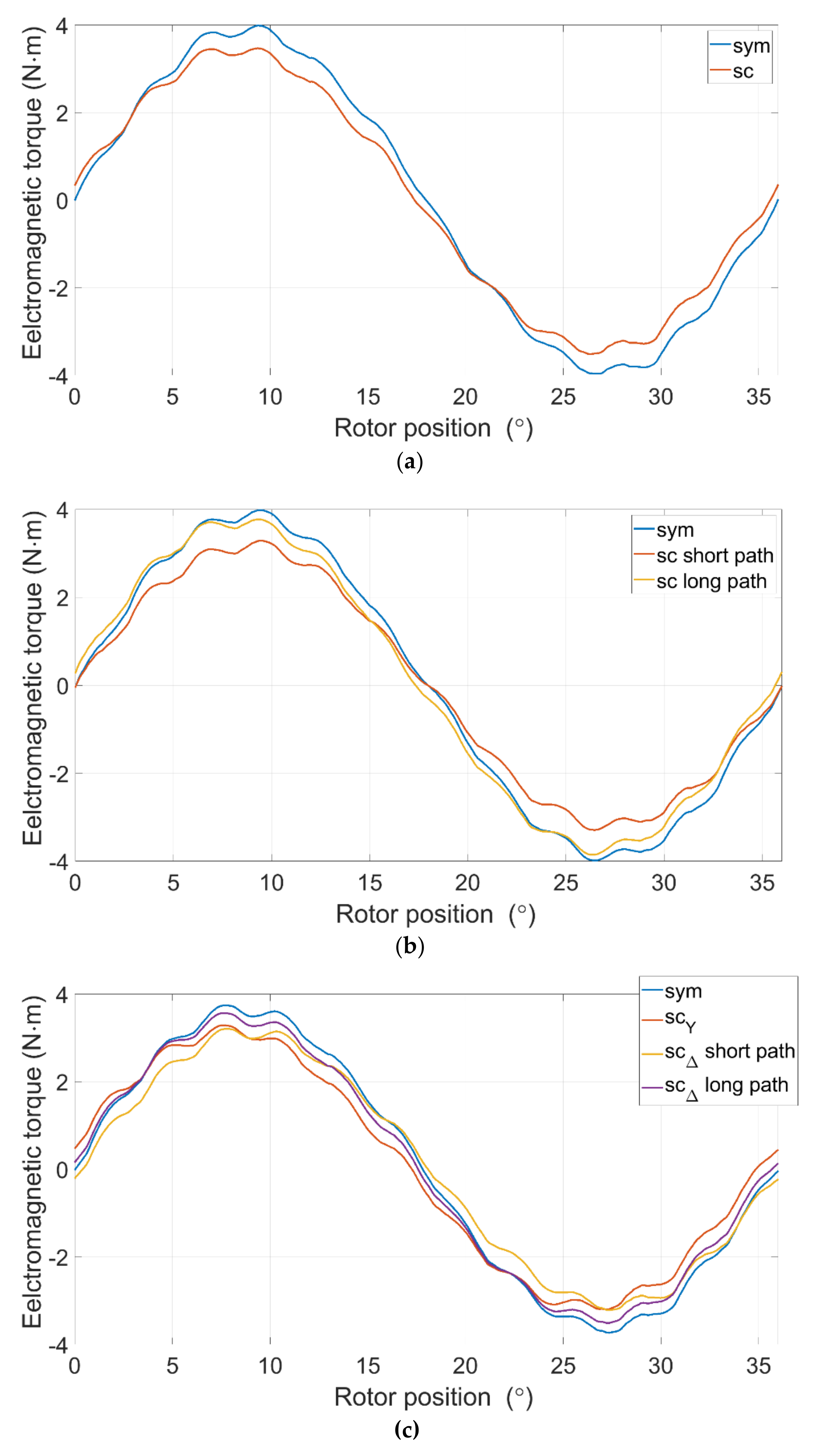
4.1.1. Waveforms of Electromagnetic Torque and Currents
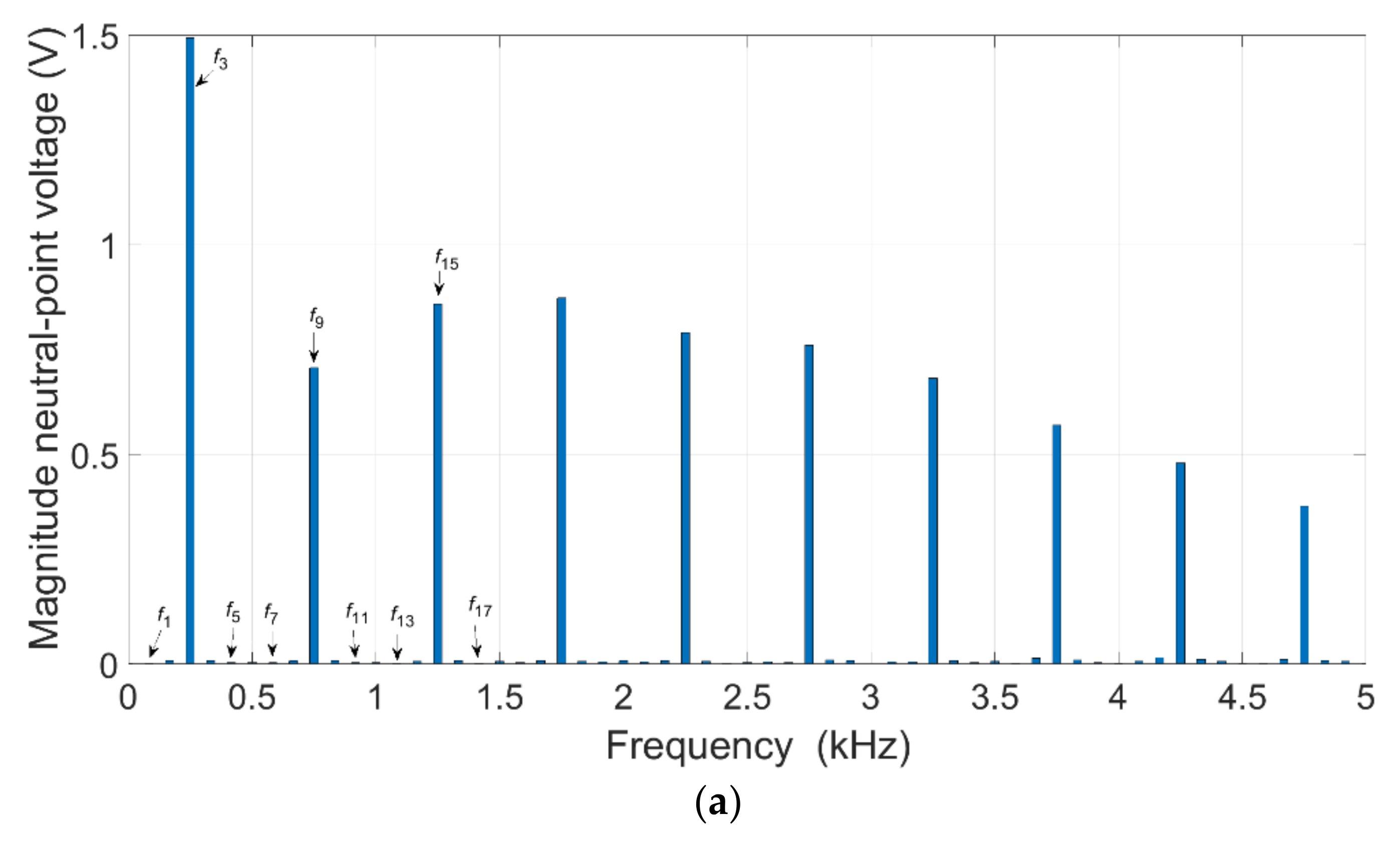
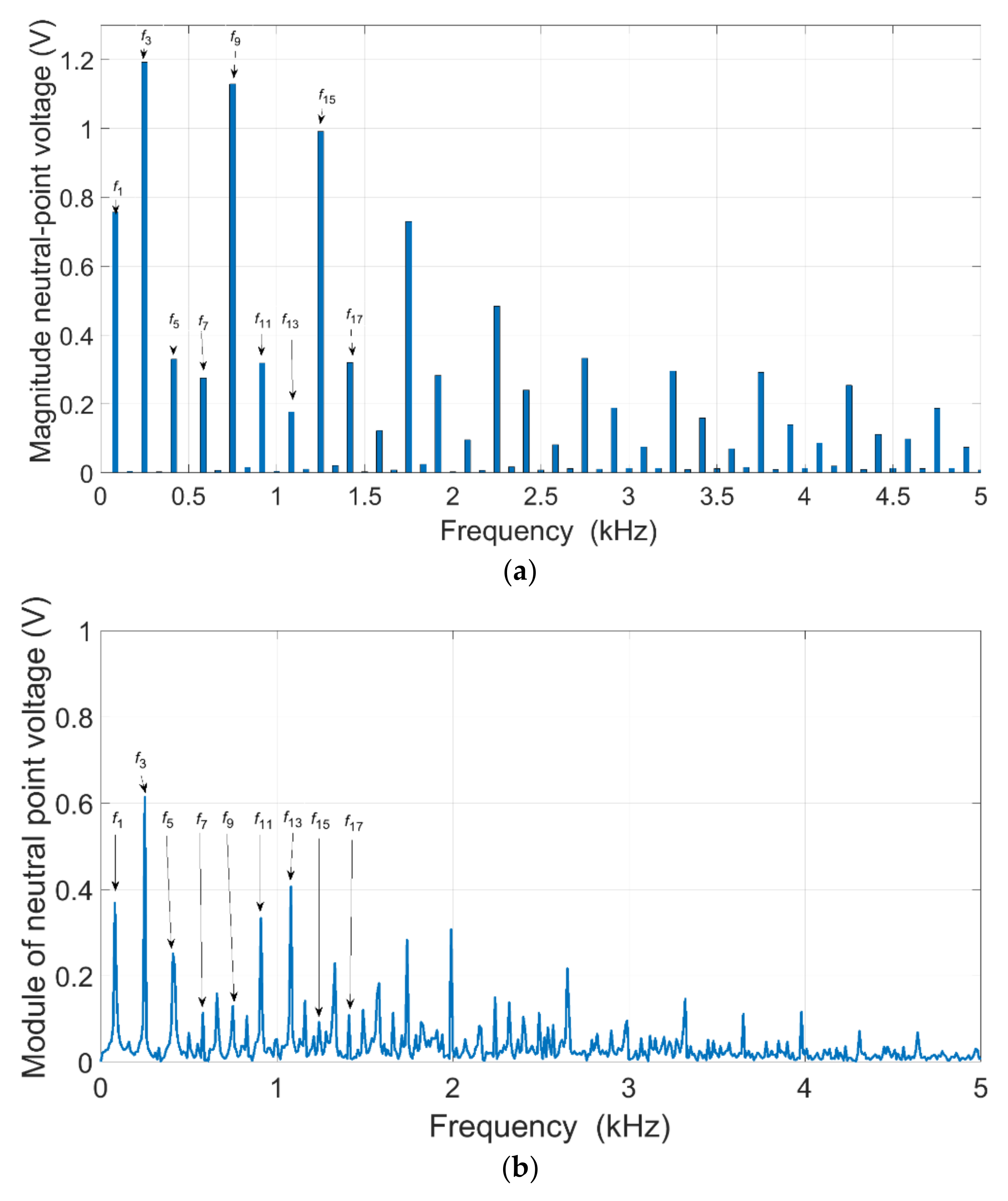
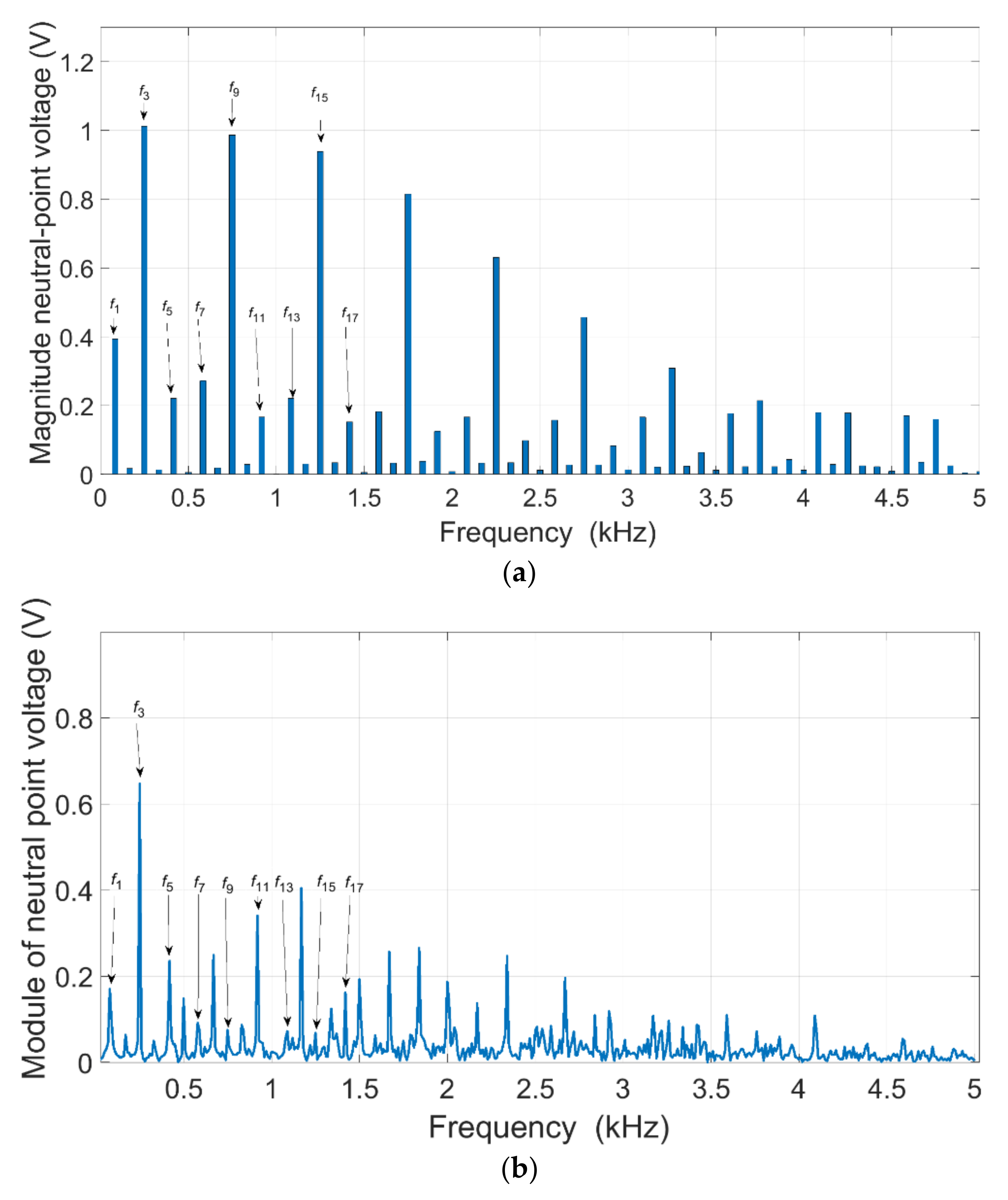
The star configuration is the most commonly used winding connection type. Both numerical calculations as well as laboratory tests were performed for the star configuration. Under numerical tests, motor current and electromagnetic torque waveforms were calculated. Assuming that the rotational speed is constant, the SC1 switch was closed at a certain point in time (t = 20 ms). Figure 5a and Figure 6 present the results of the calculations. Figure 5b presents the results of the laboratory test.
Closing of the SC1 switch, as presented in Figure 2b, causes a partial short-circuit of the Ph1 circuit. Short-circuit current isc flows through the shorted section. The value of the short-circuit current isc depends on the induced voltage (BEMF) as well as the impedance of the shorted section. The said current achieves a fixed value at a certain rotational speed, at which the effect of the resistance of the shorted element is negligible. The partial short-circuit of the winding affects the current value of not just the faulty phase. This results from the reduction of the voltage constant of the faulty Ph1 phase.

4.1.2. Y-FFT of u0

Voltage waveform u0 was recorded for the analysed conditions (Figure 2a). The voltage signal u0 is a key diagnostic signal. Relevant harmonics occurring in the voltage signal were determined based on the frequency analysis (FFT) of the voltage signal u0. Frequency analysis of the voltage u0 diagnostic signal was performed for the determined operating point. Figure 7 presents the results of the numerical calculations and of the practical test of the condition of supply of the drive system (for symmetrical operation). The faulty operation condition was verified in numerical (Figure 8a) as well as laboratory (Figure 8b) conditions.
The analysis of the proposed diagnostic signal indicates that the partial short-circuit condition of a star winding configuration is manifested by a marked increase in the first harmonic of the diagnostic signal u0 (f1 = np/60 = 83.334 Hz). The laboratory results confirm the occurrence of the winding fault condition.

4.2. Delta Configuration, Transient Analysis at Healthy Mode and under Short-Circuit Fault

4.2.1. Waveforms of Electromagnetic Torque and Currents
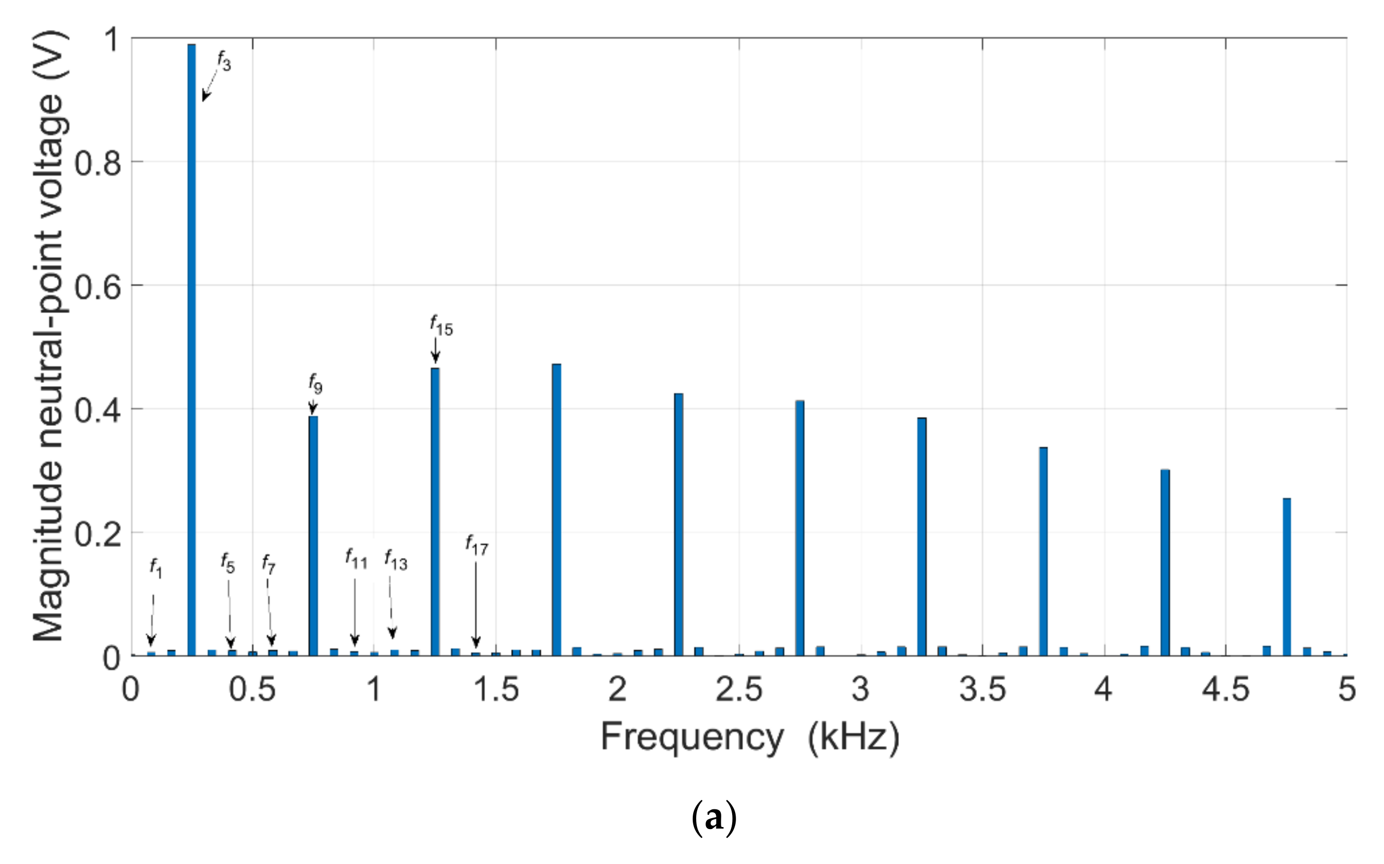
The delta configuration of windings is successfully used in small drive systems intended for use in, e.g., unmanned aerial vehicles. The operating point of the tested motor was determined for the same rotational speed and at the same electromagnetic torque. Figure 9 and Figure 10 present the results of numerical and laboratory tests. Figure 9 illustrates the waveforms of the motor currents in the symmetry condition with a transition into the short-circuit condition labelled as SC2. Figure 10 presents the waveform of the electromagnetic torque obtained in the numerical conditions.
Figure 10 presents numerical tests illustrating the electromagnetic torque.
The analysis of the test results indicates a slightly lower sensitivity of the configuration to the analysed short-circuit case.

4.2.2. FFT of u0

Figure 11 presents the analysis of the diagnostic signal for the symmetrical operation condition. Figure 12 presents faulty operation tests allowing for numerical as well as practical calculations. Voltage waveform u0 was recorded for the analysed conditions (Figure 2a). Relevant harmonics occurring in the voltage signal were determined based on the frequency analysis (FFT).
Similarly to the star configuration, the fault condition is manifested by a marked increase of the first harmonic and of selected factors. This is typical for a short-circuit condition.

4.3. Y△—Star-Delta Configuration, Transient Analysis at Healthy Mode and under Short-Circuit Fault

4.3.1. Waveforms of Electromagnetic Torque and Currents
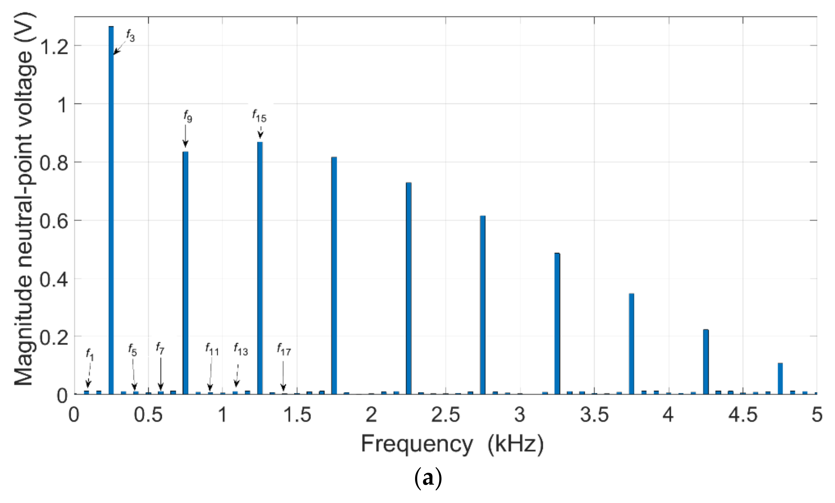
The star-delta configuration is not typically used in practice. Its use is challenging because is necessary to adjust current loads of particular winding groups. In the analysed test, it was assumed that half of the groups would feature a delta configuration. In the case of four groups, two more configurations are possible, which were not analysed in this paper. Figure 13 and Figure 14 present the transition of the star-delta winding configuration from the symmetry condition to the short-circuit condition with the short-circuit occurring in the star section (Figure 14) and in the delta section (Figure 14).
Figure 15 presents the change in the generated electromagnetic torque throughout the analysed partial short-circuit cases at the time of transition from the symmetrical operation condition.
Comparing the calculation results (Figure 14a and Figure 15a) and the test results (Figure 14b and Figure 15b), differences in the shapes and values of the currents can be noticed. The tested prototype of the motor has electrical asymmetry (different winding resistances) and magnetic asymmetry caused by rotor eccentricity. The value of the current in the laboratory tests is limited by the short-circuit resistance. The partial short-circuit condition causes a marked torque ripple increase. However, if the short-circuit occurs in the delta section, the ripple increase is significantly higher.

4.3.2. Y△—FFT of u0

For the star-delta configuration, the content of the analysed harmonics of the diagnostic signal was determined. Figure 16, Figure 17 and Figure 18 present the results of numerical and laboratory calculations for the analysis of the content of the diagnostic signal in the symmetrical operation condition (Figure 16) and after the occurrence of SC1 (Figure 17) and SC2 (Figure 18) partial short-circuit conditions.
The analysis of the relevant harmonics content of the diagnostic signal shows that a partial short-circuit in the star section causes a larger increase in the first harmonic of the diagnostic signal. Comparing the harmonics obtained by calculations (Figure 16a, Figure 17a, and Figure 18a) and by measurement (Figure 16b, Figure 17b and Figure 18b) some differences can be noticed. The calculations were performed assuming electrical and magnetic symmetry. In experimental results, electrical asymmetry causes the appearance of first harmonic (for motor without SC). Differences in the shapes of induced voltages, switching times of the devices, additional resistance of the short-circuit and eccentricity of the rotor causes the appearance of additional even harmonics. It is visible even for experimental tests of the motor without damage. The fault states aggravate this problem due to, e.g., the intensification of the eccentricity effect of the rotor.

5. Comparative Analysis

Table 4 and Table 5 present selected parameters of the tested motor for the analysed operating point (500 rpm). Table 4 presents the results of the numerical calculations, while Table 5 presents the laboratory verification. In the laboratory conditions, motor vibration as well as noise levels were recorded.
The electromagnetic torque ripple was determined based on the following relation:
σ = T e max T e min T e a v
Based on the comparison of the results of the calculations and of the laboratory tests, it is clear that the short-circuit current is significantly lower in the laboratory conditions. Its decrease was caused by the value of the resistance introduced by the extrinsic shorting circuit. The tested motor is characterised by a single-pole resistance of 35 mΩ. The lowest vibration velocity value in the state of symmetrical operation was ensured by the mixed star-delta configuration. Once the fault condition has occurred, the highest rms value of vibration velocity was recorded for the mixed star-delta configuration.
Table 6 and Table 7 present the results of the analysis of the harmonic of the voltage diagnostic signal u0.
The analysis of the content of particular harmonics of the diagnostic signal indicates that both numerical and laboratory tests confirm the increase in the base frequency (f1) as well as its factors being odd numbers (5th, 7th, etc.). In the condition of electric and magnetic symmetry of the motor, the diagnostic signal contains virtually none of these frequencies (minimal values). In actual conditions, there is always a certain degree of electrical and magnetic asymmetry between particular phases of the motor. For this reason, the results of the laboratory tests indicate an approximately fourfold increase in the basic harmonic after the occurrence of the partial short-circuit condition (while an increase of several tenfold was recorded in the course of the numerical tests). The introduction of additional resistance by means of the shorting circuit also limited the increase of the characteristic frequencies in the diagnostic signal. At the same time, the diagnostic signal is independent of the analysed configuration. In each of the analysed winding configurations, there was always an increase in the amplitude of the base frequency, the 5th, the 11th, the 17th.

6. Conclusions

This paper analyses various partial short-circuit conditions of a permanent BLDC motor for three stator winding configurations: star, delta and mixed star-delta configuration. The tests demonstrated that regardless of the winding configuration type, frequency analysis of the proposed diagnostic signal in the form of the voltage of the so-called artificial neutral point detects partial short-circuit. To some degree, the effects of a partial short-circuit depend on the winding configuration type. However, in each case, a marked increase of the 1st, 5th or the 11th harmonic of the diagnostic signal indicated the occurrence of the partial short-circuit condition. This demonstrates the versatility of the proposed diagnostic method.
Further research will be focused on the analysis of the sensitivity of the proposed motor winding fault detection method. It should be noted that in laboratory conditions, the circuit shorting a given part of the winding introduced additional resistance measured in milliohms. This represented a few tens of percent of the parameter of the shorted winding section. This limited, considerably, the value of the current flowing in the shorted section of the winding. Moreover, it limited the effect the fault had and reduced the higher harmonics content of the diagnostic signal.

Author Contributions

Conceptualization, M.K., B.P. and J.P.; methodology, M.K.; software, M.K.; validation, B.P. and J.P.; formal analysis, J.P.; investigation, M.K.; resources, M.K. and B.P.; data curation, M.K.; writing—original draft preparation, M.K.; writing—review and editing, J.P. and B.P.; visualization, M.K.; supervision, J.P.; project administration, M.K.; funding acquisition, M.K. All authors have read and agreed to the published version of the manuscript.

Funding

This research is financed in part by the statutory funds (UPB) of the Department of Electrodynamics and Electrical Machine Systems, Rzeszow University of Technology and in the part by the Minister of Education and Science of the Republic of Poland within the “Regional Initiative of Excellence” program for years 2019–2022. Project number 027/RID/2018/19, amount granted 11 999 900 PLN.

Institutional Review Board Statement

Not applicable.

Informed Consent Statement

Not applicable.

Data Availability Statement

Not applicable.

Conflicts of Interest

The authors declare no conflict of interest.

References

  1. Cao, R.; Lu, M.; Jiang, N.; Cheng, M. Comparison between Linear Induction Motor and Linear Flux-Switching Permanent-Magnet Motor for Railway Transportation. IEEE Trans. Ind. Electron. 2019, 66, 9394–9405. [Google Scholar] [CrossRef]
  2. McElveen, R.F.; Holub, R.A.; Martin, W.E. Replacing Induction Motors with Caged-Rotor Permanent Magnet Motors: Application Considerations and Cost Analysis. IEEE Ind. Appl. Mag. 2020, 26, 67–75. [Google Scholar] [CrossRef]
  3. Marcic, T.; Stumberger, B.; Stumberger, G. Comparison of Induction Motor and Line-Start IPM Synchronous Motor Performance in a Variable-Speed Drive. IEEE Trans. Ind. Appl. 2012, 48, 2341–2352. [Google Scholar] [CrossRef]
  4. Melfi, M.J.; Evon, S.; McElveen, R. Induction versus permanent magnet motors. IEEE Ind. Appl. Mag. 2009, 15, 28–35. [Google Scholar] [CrossRef]
  5. Ni, R.; Xu, D.; Wang, G.; Gui, X.; Zhang, G.; Zhan, H.; Li, C. Efficiency Enhancement of General AC Drive System by Remanufacturing Induction Motor with Interior Permanent-Magnet Rotor. IEEE Trans. Ind. Electron. 2016, 63, 808–820. [Google Scholar] [CrossRef]
  6. Wang, H.; Li, J.; Qu, R.; Lai, J.; Huang, H.; Liu, H. Study on High Efficiency Permanent Magnet Linear Synchronous Motor for Maglev. IEEE Trans. Appl. Supercond. 2018, 28, 0601005. [Google Scholar] [CrossRef]
  7. Chin, J.-W.; Cha, K.-S.; Park, M.-R.; Park, S.-H.; Lee, E.-C.; Lim, M.-S. High Efficiency PMSM with High Slot Fill Factor Coil for Heavy-Duty EV Traction Considering AC Resistance. IEEE Trans. Energy Convers. 2021, 36, 883–894. [Google Scholar] [CrossRef]
  8. Hwang, Y.-H.; Lee, J. HEV Motor Comparison of IPMSM With Nd Sintered Magnet and Heavy Rare-Earth Free Injection Magnet in the Same Size. IEEE Trans. Appl. Supercond. 2018, 28, 5206405. [Google Scholar] [CrossRef]
  9. Park, Y.; Kim, H.; Jang, H.; Ham, S.-H.; Lee, J.; Jung, D.-H. Efficiency Improvement of Permanent Magnet BLDC with Halbach Magnet Array for Drone. IEEE Trans. Appl. Supercond. 2020, 30, 5201405. [Google Scholar] [CrossRef]
  10. Jiang, X.; Huang, W.; Cao, R.; Hao, Z.; Jiang, W. Electric Drive System of Dual-Winding Fault-Tolerant Permanent-Magnet Motor for Aerospace Applications. IEEE Trans. Ind. Electron. 2015, 62, 7322–7330. [Google Scholar] [CrossRef]
  11. Sarigiannidis, A.G.; Beniakar, M.E.; Kakosimos, P.E.; Kladas, A.G.; Papini, L.; Gerada, C. Fault Tolerant Design of Fractional Slot Winding Permanent Magnet Aerospace Actuator. IEEE Trans. Transp. Electrif. 2016, 2, 380–390. [Google Scholar] [CrossRef]
  12. Bosso, A.; Conficoni, C.; Raggini, D.; Tilli, A. A Computational-Effective Field-Oriented Control Strategy for Accurate and Efficient Electric Propulsion of Unmanned Aerial Vehicles. IEEE/ASME Trans. Mechatron. 2021, 26, 1501–1511. [Google Scholar] [CrossRef]
  13. Lee, S.-T.; Hur, J. Detection Technique for Stator Inter-Turn Faults in BLDC Motors Based on Third-Harmonic Components of Line Currents. IEEE Trans. Ind. Appl. 2017, 53, 143–150. [Google Scholar] [CrossRef]
  14. Zhou, Y.; Lin, X.; Cheng, M. A Fault-Tolerant Direct Torque Control for Six-Phase Permanent Magnet Synchronous Motor with Arbitrary Two Opened Phases Based on Modified Variables. IEEE Trans. Energy Convers. 2016, 31, 549–556. [Google Scholar] [CrossRef]
  15. Zhao, W.; Wu, B.; Chen, Q.; Zhu, J. Fault-Tolerant Direct Thrust Force Control for a Dual Inverter Fed Open-End Winding Linear Vernier Permanent-Magnet Motor Using Improved SVPWM. IEEE Trans. Ind. Electron. 2018, 65, 7458–7467. [Google Scholar] [CrossRef]
  16. Huang, W.; Hua, W.; Chen, F.; Yin, F.; Qi, J. Model Predictive Current Control of Open-Circuit Fault-Tolerant Five-Phase Flux-Switching Permanent Magnet Motor Drives. IEEE J. Emerg. Sel. Top. Power Electron. 2018, 6, 1840–1849. [Google Scholar] [CrossRef]
  17. Ullah, Z.; Hur, J. A Comprehensive Review of Winding Short Circuit Fault and Irreversible Demagnetization Fault Detection in PM Type Machines. Energies 2018, 11, 3309. [Google Scholar] [CrossRef] [Green Version]
  18. Jafari, A.; Faiz, J.; Jarrahi, M.A. A Simple and Efficient Current-Based Method for Interturn Fault Detection in BLDC Motors. IEEE Trans. Ind. Inform. 2021, 17, 2707–2715. [Google Scholar] [CrossRef]
  19. Shifat, T.A.; Hur, J.-W. ANN Assisted Multi Sensor Information Fusion for BLDC Motor Fault Diagnosis. IEEE Access 2021, 9, 9429–9441. [Google Scholar] [CrossRef]
  20. Nejjari, H.; Benbouzid, M.E.H. Monitoring and diagnosis of induction motors electrical faults using a current Park’s vector pattern learning approach. IEEE Trans. Ind. Appl. 2000, 36, 730–735. [Google Scholar] [CrossRef]
  21. Awadallah, M.; Morcos, M. Diagnosis of stator short circuits in brushless DC motors by monitoring phase voltages. IEEE Trans. Energy Convers. 2005, 20, 246–247. [Google Scholar] [CrossRef]
  22. Siddique, A.; Yadava, G.; Singh, B. A review of stator fault monitoring techniques of induction motors. IEEE Trans. Energy Convers. 2005, 20, 106–114. [Google Scholar] [CrossRef]
  23. Yang, S. Online Stator Turn Fault Detection for Inverter-Fed Electric Machines Using Neutral Point Voltages Difference. IEEE Trans. Ind. Appl. 2016, 52, 4039–4049. [Google Scholar] [CrossRef]
  24. Jung, J.-H.; Lee, J.-J.; Kwon, B.-H. Online Diagnosis of Induction Motors Using MCSA. IEEE Trans. Ind. Electron. 2006, 53, 1842–1852. [Google Scholar] [CrossRef]
  25. Lee, S.B.; Hyun, D.; Kang, T.-j.; Yang, C.; Shin, S.; Kim, H.; Park, S.; Kong, T.-S.; Kim, H.-D. Identification of False Rotor Fault Indications Produced by Online MCSA for Medium-Voltage Induction Machines. IEEE Trans. Ind. Appl. 2016, 52, 729–739. [Google Scholar] [CrossRef]
  26. Korkosz, M.; Prokop, J.; Pakla, B.; Podskarbi, G.; Bogusz, P. Analysis of Open-Circuit Fault in Fault-Tolerant BLDC Motors with Different Winding Configurations. Energies 2020, 13, 5321. [Google Scholar] [CrossRef]
  27. Misir, O.; Raziee, S.M.; Hammouche, N.; Klaus, C.; Kluge, R.; Ponick, B. Prediction of Losses and Efficiency for Three-Phase Induction Machines Equipped With Combined Star–Delta Windings. IEEE Trans. Ind. Appl. 2017, 53, 3579–3587. [Google Scholar] [CrossRef]
  28. Lei, Y.; Zhao, Z.; Wang, S.; Dorrell, D.G.; Xu, W. Design and Analysis of Star–Delta Hybrid Windings for High-Voltage Induction Motors. IEEE Trans. Energy Convers. 2011, 58, 3758–3767. [Google Scholar]
  29. Ibrahim, M.N.F.; Rashad, E.; Sergeant, P. Performance Comparison of Conventional Synchronous Reluctance Machines and PM-Assisted Types with Combined Star–Delta Winding. Energies 2017, 10, 1500. [Google Scholar] [CrossRef]
  30. Korkosz, M.; Prokop, J.; Pakla, B.; Bogusz, P. Frequency analysis in fault detection of dual-channel BLDC motors with combined star-delta winding. IET Electr. Power Appl. 2021, 15, 824–836. [Google Scholar] [CrossRef]
Figure 1. A hybrid drive system featuring a BLDC motor.
Energies 15 00196 g001
Figure 2. The schematic diagram (a) of the power supply of the BLDC motor and of the winding configurations: (b) star (Y), (c) delta (Δ) and (d) mixed star-delta configuration (YΔ).
Energies 15 00196 g002
Figure 3. The static characteristics of the electromagnetic torque for the following configurations: (a) star, (b) delta, (c) mixed star-delta.
Energies 15 00196 g003
Figure 4. Induced voltages for particular configurations: (a) star, (b) delta, (c) star-delta.
Energies 15 00196 g004aEnergies 15 00196 g004b
Figure 5. Y configuration -waveforms of line currents, healthy to SC1 (a) numerical calculations, (b) laboratory tests.
Energies 15 00196 g005
Figure 6. Y configuration-waveforms of electromagnetic torque, healthy to SC1- numerical calculations.
Energies 15 00196 g006
Figure 7. Y configurations—FFT of neutral voltage—healthy: (a) numerical calculations, (b) measurement.
Energies 15 00196 g007aEnergies 15 00196 g007b
Figure 8. Y configurations—FFT of neutral voltage—SC: (a) numerical calculations, (b) measurement.
Energies 15 00196 g008
Figure 9. △ configuration—waveforms of line currents—healthy to SC2 (a) numerical calculations; (b) laboratory tests.
Energies 15 00196 g009
Figure 10. △ configuration—waveforms of electromagnetic torque delta—healthy to SC2.
Energies 15 00196 g010
Figure 11. △ configuration—FFT of neutral voltage—healthy: (a) numerical calculations, (b) measurement.
Energies 15 00196 g011aEnergies 15 00196 g011b
Figure 12. △ configuration—FFT of neutral voltage—SC2: (a) numerical calculations, (b) measurement.
Energies 15 00196 g012
Figure 13. Y△ configuration—waveforms of line currents—healthy to SC1: (a) numerical calculations, (b) laboratory tests.
Energies 15 00196 g013
Figure 14. Y△ configuration—waveforms of currents—healthy to SC2: (a) numerical calculations, (b) laboratory tests.
Energies 15 00196 g014
Figure 15. Y△ configuration—waveforms of electromagnetic torque (a) healthy to SC1, (b) healthy to SC2.
Energies 15 00196 g015aEnergies 15 00196 g015b
Figure 16. Y△ configurations—FFT of neutral voltage—healthy: (a) numerical calculations, (b) measurement.
Energies 15 00196 g016aEnergies 15 00196 g016b
Figure 17. Y△ configurations—FFT of neutral voltage—SC1: (a) numerical calculations, (b) measurement.
Energies 15 00196 g017
Figure 18. Y△ configurations—FFT of neutral voltage—SC2: (a) numerical calculations, (b) measurement.
Energies 15 00196 g018
Table 1. Selected parameters of motor for UAV application.
ParameterValue
Rated voltage Udc52 VDC
Rated torque TL4 N·m
Rated speed n8000 rpm
Winding configurationDelta
Number of parallel winding group4
Number of turns per phase Nph120
Number of shorted turns Nsc30
Resistance of stator pole Rb0.035 Ω
Number of stator slots Ns24
Number of poles p20
Permanent magnetN48SH
Type of rotoroutrunner
Air-gap δ0.45 mm
Rotor diameter Dr102 mm
Stator diameter Ds93.4 mm
Active length lFe25 mm
Table 2. Torque constant kT.
kT\Winding ConfigurationY
[N⋅m/Arms]
Δ
[N⋅m/Arms]

[N⋅m/Arms]
Symmetry0.370.210.28
SC10.32-0.24
SC2-0.15/0.190.24/0.27
Table 3. Voltage constant KE.
KE\Winding ConfigurationY Δ
[Vrms⋅s/rad][Vrms⋅s/rad][Vrms⋅s/rad]
Symmetry0.4020.230.263
SC1-Ke120.35-0.255
SC1-Ke230.408-0.305
SC1-Ke310.353-0.253
SC2-Ke12-0.2170.277
SC2-Ke23-0.2210.297
SC2-Ke31-0.1860.261
Table 4. Selected motor parameters—numerical calculations.
Parameter/Winding ConfigurationYΔ
SymSC1SymSC2SymSC1SC2
TL [N·m]21.962.011.972.022.311.74
σ [%]34.292.928.972.129.268.8140
I1RMS [A]4.317.817.6712.046.0812.18.74
I2RMS [A]4.316.497.6712.546.089.987.52
I3RMS [A]4.316.787.6712.546.0810.169.2
ISCRMS [A]-23.79-22.87-22.8522.85
IDCav [A]5.077.969.0614.36711.789.61
Table 5. Selected motor parameters—laboratory tests.
Parameter/Winding ConfigurationYΔ
SymSC1SymSC2SymSC1SC2
Teav [N·m]21.8821.7721.941.66
I1RMS [A]4.785.928.9810.196.38.96.99
I2RMS [A]4.7368.2610.196.27.97.5
I3RMS [A]4.685.968.1610.46.38.17.3
ISCRMS [A]-11.8-11.63-10.611.69
vRMS[mm/s]0.20.30.190.340.170.360.36
noisy [dB]59.768.159.567.35967.367.4
Table 6. FFT of u0—numerical calculations.
Harmonic/Winding ConfigurationYΔ
SymSC1SymSC2SymSC1SC2
f1 [mV]2.76916.445312.4756394
f3 [mV]14931018988715126611931013
f5 [mV]3.32838.918810.9331221
f7 [mV]3.43009.823911.3276272
f9 [mV]7.0610633885898361132989
f11 [mV]3.62647.11576.5328167
f13 [mV]2.323810.120511.1178221
f15 [mV]8581115465583869995942
f17 [mV]2.22785.31442.9321153
Table 7. FFT of u0—laboratory tests.
Harmonic/Winding ConfigurationYΔ
SymSC1SymSC2SymSC1SC2
f1 [mV]622903717350.7157170
f3 [mV]1004827718599723613647
f5 [mV]371491612040251236
f7 [mV]3719719405411491
f9 [mV]37218219612525112975
f11 [mV]902833219655333340
f13 [mV]4822630857540672
f15 [mV]32412518451.21759268
f17 [mV]1042273814444108124
Publisher’s Note: MDPI stays neutral with regard to jurisdictional claims in published maps and institutional affiliations.

