Review

Thermal Management System Architecture for Hydrogen-Powered Propulsion Technologies: Practices, Thematic Clusters, System Architectures, Future Challenges, and Opportunities

by
Akshay Nag Srinath
1,
Álvaro Pena López
1,
Seyed Alireza Miran Fashandi
2,
Sylvain Lechat
1,
Giampiero di Legge
3,
Seyed Ali Nabavi
3,
Theoklis Nikolaidis
1 and
Soheil Jafari
1,*
1
Centre of Propulsion Engineering, Cranfield University, Bedford MK43 0AL, UK
2
Department of Mechanical Engineering, Iran University of Science and Technology, Tehran 13114-16846, Iran
3
Centre for Climate and Environmental Protection, Cranfield University, Bedford MK43 0AL, UK
*
Author to whom correspondence should be addressed.
Energies 2022, 15(1), 304; https://doi.org/10.3390/en15010304
Submission received: 24 November 2021 / Revised: 19 December 2021 / Accepted: 1 January 2022 / Published: 3 January 2022
(This article belongs to the Section J: Thermal Management)

Abstract

:
The thermal management system architectures proposed for hydrogen-powered propulsion technologies are critically reviewed and assessed. The objectives of this paper are to determine the system-level shortcomings and to recognise the remaining challenges and research questions that need to be sorted out in order to enable this disruptive technology to be utilised by propulsion system manufacturers. Initially, a scientometrics based co-word analysis is conducted to identify the milestones for the literature review as well as to illustrate the connections between relevant ideas by considering the patterns of co-occurrence of words. Then, a historical review of the proposed embodiments and concepts dating back to 1995 is followed. Next, feasible thermal management system architectures are classified into three distinct classes and its components are discussed. These architectures are further extended and adapted for the application of hydrogen-powered fuel cells in aviation. This climaxes with the assessment of the available evidence to verify the reasons why no hydrogen-powered propulsion thermal management system architecture has yet been approved for commercial production. Finally, the remaining research challenges are identified through a systematic examination of the critical areas in thermal management systems for application to hydrogen-powered air vehicles’ engine cooling. The proposed solutions are discussed from weight, cost, complexity, and impact points of view by a system-level assessment of the critical areas in the field.

1. Introduction

Stringent environmental regulations set on fossil fuels and ambitious net-zero targets has resulted in new research that focuses on alternative fuels as potential enablers of low or zero carbon technologies [1]. In the aviation sector, the ACARE (Advisory Council for Aeronautics Research in Europe) has announced the Flight Path 2050 in which stringent targets are stated for civil aircraft of the next generation (e.g., 75% reduction in CO2 emissions per passenger kilometre and a 90% reduction in NOX emissions of flying aircraft relative to the capabilities of typical new aircraft in 2000) [2]. To overcome these severe limitations, compressed or liquefied hydrogen have been proposed as a promising option owing to its possible benefits of zero-carbon emission due to a clean combustion [3,4,5]. As an alternative fuel, hydrogen offers several advantages, including high specific energy (~2.8 times of the jet fuel), global availability, and safety [6]. However, one of the practical bottlenecks in the implementation and technology development procedure of hydrogen-powered air vehicles is the thermal management of the system. Hydrogen has a very low boiling point (−252.87 °C) that could result in boil off in storage or OH radicals that form a greenhouse gas [7]. Therefore, evident system shortcomings should be established, and remaining research challenges should be identified to enable this disruptive technology to be utilised by air vehicle manufacturers.
The focus of this paper is on the thermal management system architecture design, current and future challenges, and proposing potential solutions for a hydrogen-powered propulsion technologies. This objective has been achieved through the following steps:
Section 2 addresses a systematic scientometrics analysis in the field and identifies the key milestones and fundamental articles through a methodological data collection approach. Further, a critical literature review is conducted to identify the thematic clusters and remaining research questions as well as to clarify the technology trend in the field.
In Section 3, the concept of thermal management and its role in hydrogen-powered propulsion system performance is presented, and different components are analysed separately. With regards to the identified research and practical challenges, three fuel system architectures for the utilisation of hydrogen are proposed to cope with the thermal loads generated by heat sources in thermal management system architecture. The pros and cons of each architecture are also discussed in detail. Further, the said three architectures are extended to be adopted to the applications of the fuel cells in aviation for illustration and discussions.
Section 4 opens the discussion on research challenges and key issues that are to be addressed from the thermal management and fuel system design viewpoints to enable a hydrogen-powered propulsion system to be adopted by air vehicles’ engine designers and manufacturers. The proposed architectures are argued from different points of view, including weight, cost, complexity, and impact by system-level examination of the critical areas in the field.
Conclusion remarks are summarised in Section 5.

2. Scientometrics and Literature Review

One of the scientometric tools used in technology trend identification is the co-word analysis. Co-word analysis is a well-known concept across various scientific fields and aims to identify the connections between relevant ideas by considering the patterns of co-occurrence of words. Concerning scientific publications, this method mainly examines the titles, abstracts, and available portions of documents [8]. First developed in the 1980s, it assumes that similar keywords in documents are a sign of proximity between them that enables to demarcate different structures, ideas, and components. Accordingly, the reader(s) can obtain an overview of important subjects and detect hidden relationships as well as possible interdependencies [9,10]. Other benefits of this technique include the development of hierarchical patterns of concepts and the ability to cluster relevant fields of knowledge. The immediate merit of this approach is in simplifying the process of policymaking for science and technology.
In this study, the scientometric analysis is performed with the below objectives:
Identifying the fundamental articles (i.e., those with the highest number of citations/impact) in the chosen field of study, i.e., the Thermal Management Systems (TMS) for Hydrogen Propulsion. This goal is realised by analysing the Web of Science (WoS) [11] using the HistCite software [12].
Finding the technology trend in the field of TMS for Hydrogen Propulsion via the Scopus database [13] and VOSViewer software [14].

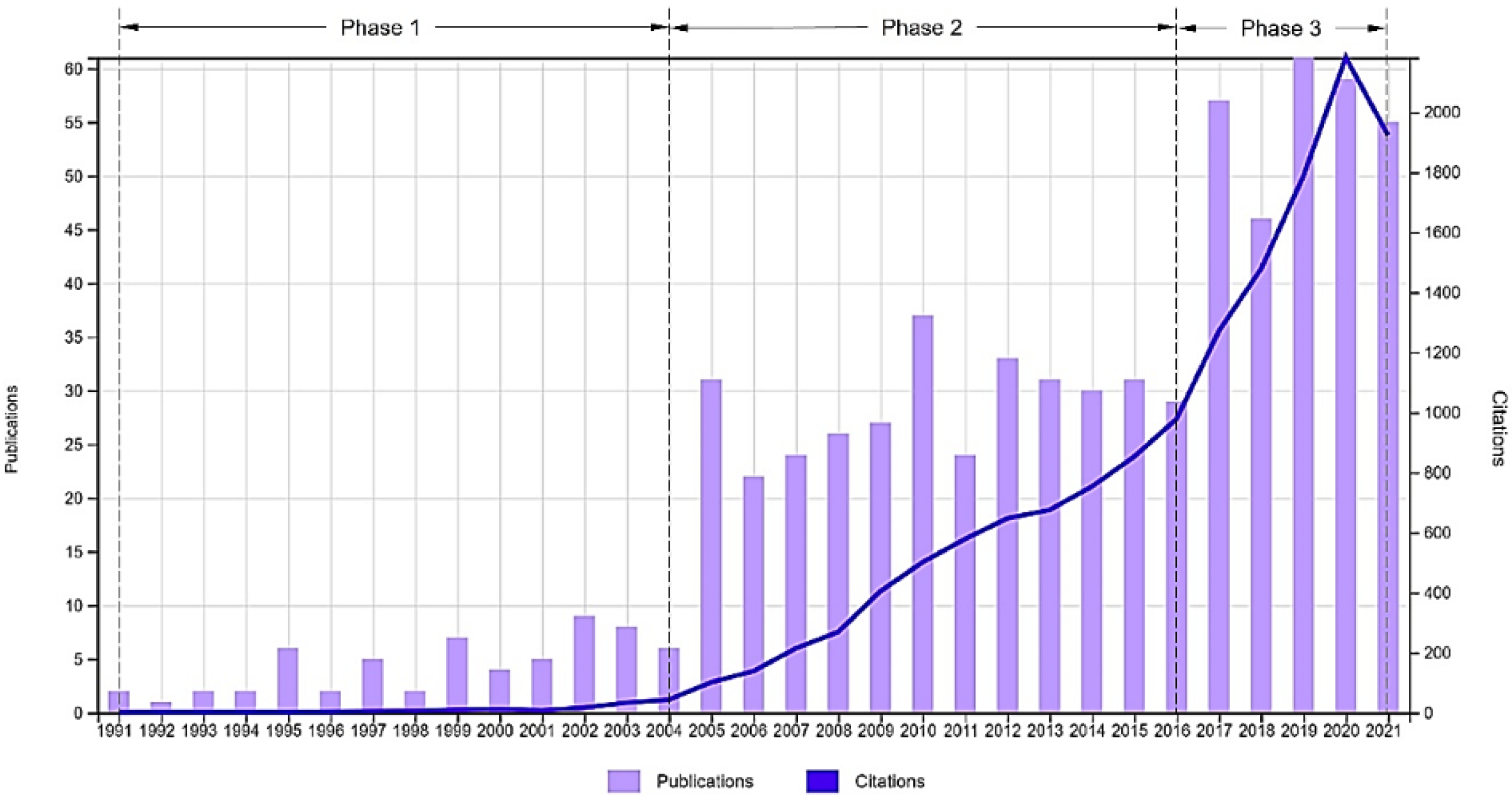
2.1. Methodology and Data Collection

The primary and vital step to perform the scientometric analysis is to determine the database for review and the search strategy. In this step, search terms are created using the keywords associated with the chosen field. Subsequently, by introducing these conceived search terms in the advanced search section of the database, the articles containing the associated search terms in their title, abstract and keywords are obtained.
On 24 September 2021, 684 related articles were retrieved from the WoS database. Furthermore, 1149 articles were retrieved from the Scopus database. The rationale for using the WoS database is that Histcite only accepts data from WoS as its input. Likewise, the Citation Analysis to identify the key articles were conducted using HistCite.
With regards to the analysis of the technology trend, since the output data of the Scopus database are more extensive in number in comparison with that of WoS, relying on the Scopus database was beneficial to determine the trend comprehensively. The publication and citation of articles in the research field over different years in WoS are shown in Figure 1.
To evaluate the trend in technology development in the TMS for Hydrogen Propulsion over various years, three-time periods (i.e., Phase 1, 2, and 3) are selected based on the publications and citations of articles. The chosen periods are shown in Figure 1 and are as below:
  • Phase 1—1991 to 2004 (timespan inclusive of both years).
  • Phase 2—2005 to 2016 (timespan inclusive of both years).
  • Phase 3—2017 to 2021 (timespan inclusive of both years).

2.2. Identification of Fundamental Articles

After obtaining the required data from WoS, they are imported to HistCite for citation analysis. The most cited articles are ranked based on the citation score (TGCS) since the higher citations implies that the quality of that article is higher in the field of research. On this basis, some of the most important articles are described and presented in Table 1, along with the information like the authors, title, and their year of publication. The papers listed in Table 1 are deemed highly relevant by the authors as many works of literature cited them and spanned over all the three phases mentioned above. They address the need and importance of utilising hydrogen as fuel while also catering for a few particular aspects of the TMS, which is the main subject of this paper. Hence, their importance in developing the work presented in this paper is significant.

2.3. Identification of Technology Trend

The data obtained from Scopus was imported into VOSViewer to establish the co-occurrence network of keywords and their clusters. Each network consists of a set of clusters in which the keywords within each cluster are related thematically related. There is also a thematic connection between the keywords of specific clusters. Based on the Co-word Analysis method, this paper will identify the technology trend.
According to the co-word analysis, a frequently repeated pair of keywords in an article implies a strong semantic connection. The level of semantic connection rises as the number of such pairs increases so that a deeper cognitive connection between articles of the same field can be discovered. As a side note, this method has the potential to delineate the dynamics of science in general [45,46,47]. Social and basic sciences have used this approach to their advantage to map the relations among different concepts and subjects. This method has also been successfully used in tracking fundamental changes and chronology of social and perceptual networks [48].
In the subsequent sections, the data from the above-mentioned phases are studied independently, and their clusters are scrutinised.

2.3.1. Phase 1 (Timespan—1991 to 2004)

The main topics in Phase 1 are categorised under 168 keywords and 27 clusters. For this purpose, the co-occurrence threshold for the keywords is to be selected as one. Thus, implying that these 168 keywords are repeated at least once in the title/abstract/keywords of the articles. Choosing two as the co-occurrence threshold would have given us 22 keywords and seven clusters. Since the objective of this paper is to examine all the subjects in this phase, a co-occurrence threshold of one is selected. The co-occurrence network of keywords in this phase is shown in Figure 2.
Different clusters in this figure are displayed with different colours. It can be observed that some clusters resemble separate islands that have no thematic relationship with other clusters. It seems that these subjects have been mentioned for the first time in this phase. In Figure 2, keywords with a more significant occurrence are shown in a larger circle.
The top keywords from Phase 1 (1991–2004) that form into 27 clusters are tabulated in Table 2. Furthermore, Table 3 (which is tabulated for occurrences greater than two) indicates the main topics of this phase in the form of keywords, occurrences, and total link strength.

2.3.2. Phase 2 (Timespan—2005 to 2016)

The main topics in Phase 2 are grouped under 178 keywords and 23 clusters. To this end, the co-occurrence threshold of words is taken as two. Thus, implying that 178 keywords are repeated at least twice in the title/abstract/keywords of the article. Choosing three as the co-occurrence threshold would yield 75 keywords and 14 clusters. Once again, with the objective of this paper to investigate all the subjects discussed in this phase, a co-occurrence threshold of two is selected.
The co-occurrence network of words in this phase is shown in Figure 3. The number of clusters separated from the others is small. This indicates the deeper connection between the subjects in this phase.
The top keywords from Phase 2 (2005–2016) that form into 23 clusters are tabulated in Table 4. In addition, Table 5 (tabulated for occurrences greater than five) indicates the main topics of this phase in the form of keywords, occurrences, and total link strength.

2.3.3. Phase 3 (Timespan 2017 to 2021)

The main topics in Phase 3 are categorised under 115 keywords and 16 clusters. For this purpose, the co-occurrence threshold of words is taken as two, implying that the 115 keywords are repeated at least twice in the title/abstract/keywords section of the articles. Choosing three as the co-occurrence threshold would have given us 53 keywords and eight clusters. Since the aim of this study in this phase is to investigate all related subjects, a co-occurrence threshold of two is selected.
The co-occurrence network of keywords in this phase is shown in Figure 4. This indicates that the considered subjects in this research and their relationship with one another are well identified by researchers. It is observed that only two clusters seem to have no thematic relationship with other clusters at the time of this study.
The top keywords from Phase 3 (2017 to 2021) that form into 16 clusters are tabulated in Table 6. In addition, the occurrences of keywords greater than four are tabulated in Table 7.
From the Scientometrics and literature review, in Phase 1, it is observed that keywords such as combined cycle, fuel cell, gas turbine, solid oxide fuel cell, thermal efficiency, and heat transfer have very strong links. Progression to Phase 2 shows a further increase in the link strength for keywords in Phase 1 while introducing new keywords of comparable link strength such as hydrogen, SOFC, hybrid system, exergy, optimization, micro gas turbine, exergy analysis, MCFC, cogeneration, among many. Even in Phase 3, the link strength of the keywords from Phase 1 and Phase 2 increases, and additional keywords of comparable strengths come into view, following a similar trend as observed with previous Phases.
It is also worth noting that the focus on power generation with hybrid systems and optimising such cycles for better performance has been at the forefront of many of these researches. Although some literature focuses on aviation applications, it is recommended for the reader(s) to adopt best practices from both the domains of research to develop suitable and optimum TMS for applications of Hydrogen in aviation. The subsequent sections of this paper address the topics related to TMS with the utilisation of hydrogen in the viewpoint and envision the prospective Engine Fuel System architectures that benefit the engine performance.

3. Thermal Management

Thermal Management is a concept of utilising the engine fluid systems to extract the excess heat generated within the various components and systems of the engine and employing the extracted heat for multiple functions that would improve the engine’s performance. Thus, developing any TMS for an aero-engine requires integrating all the three Fluid Systems in the engine, i.e., the Air, Oil, and Fuel Systems [49,50].
As the aero-engine technology transitions towards higher Overall Pressure Ratios (OPRs) and higher By-pass Ratios (BPRs) to achieve the demands of higher thrust, power, and improved Specific Fuel Consumptions (SFC) [4], some of the key challenges from the TMS perspective are,
  • The higher component temperatures.
  • The higher temperature of the working fluids.
  • Higher heat generated within the Engine and its sub-systems owing to points 1 and 2.
Therefore, the TMS and its significance in effectively utilising the excess heat to improve the engine performance becomes a critical issue. In the state-of-the-art aero-engine technologies, the recognised heat sources for which the TMS design caters decisively are accessory gearbox (AGB), bearings, pumps, and generators. Furthermore, the power gearbox and the constant speed drives in the geared turbofan engines are also heat sources that require the effective TMS to enhance its performance and operability [50].
To simplify, the main objectives of the TMS are to [49],
  • Maximise the utilisation of heat generated and avoid unnecessary heat losses.
  • Enable various components and systems to operate at an acceptable limit to ensure higher component life and performance and thereby reduce the intervention for maintenance and services and so forth.
From the Thermal Management perspective, it is worthwhile to note the primary functions of the said Fluid Systems in the engine, and they are classified broadly as [49],
  • Fuel System—Designed to act as a heat sink for the Oil System that scavenges heat from various components/systems in the engine.
  • Oil System—Designed to scavenge the excess heat while providing essential cooling and corrosion protection to specific components/systems in the engine.
  • (Internal or Secondary) Air System—Aids in cooling the engine components, anti-icing, and cabin environment control.
Although the cooling flow of air is deemed a heat load management practice for the engine components, this does not fall within the scope of this paper. However, the reader(s) can note that a comprehensive review of the cooling mechanisms, physics-based modelling and associated studies, along with the involved control system mechanisms, are available in the literature [50]. Yet another aspect of the air system that is associated with the thermal management is an integration with the oil system where the heat exchangers like the surface air-cooled oil Coolers (SACOC) are employed to further maintain the required operating temperature of the oil, following a heat exchange between the oil and fuel system via the fuel oil heat exchanger (FOHE).
Thus, a visualisation of the thermal management model, which is typical and simplified, is as shown in Figure 2.
The origin of this model is through a patent registered in 1987 by United Technologies Corporation based on an integration of the fuel, oil, and air systems to meet the cooling requirements of gas turbine engines [50]. For the benefit of the reader(s), it is worth noting that important information is available in the literature, such as the historical development in the area of TMS for gas turbines, various configurations for consideration. In addition, the utilisation of different working fluids such as water, therminol, and thermally neutral heat transfer fluid (TNHTF) are addressed [50].
The TMS model shown in Figure 5 is acceptable as a preliminary concept for an aero-engine that utilises Hydrogen as the fuel. Hydrogen is in its gaseous state at room temperature due to its low boiling point (−20.1 K at 1 atm pressure), while its auto-ignition temperature is much higher at 773 K in comparison to its counterpart convention fossil fuels [51,52]. Thus, from a thermal management perspective and to further optimise the engine’s performance, the wide temperature range for operation is offered by hydrogen as it can act as a heat sink.
A typical fuel-cooled thermal management model, i.e., the fuel system architecture employed in the current technologies, can be visualised in Figure 6. Thus, it enables the heat dissipation from various engine sources to the fuel raising its temperature to the desired value before introducing it into the combustor.
The fuel system architecture shown in Figure 6 is typical of the state-of-the-art engine technologies available in the market. For the application of hydrogen as fuel in the engine, the current model requires further modifications. The modifications necessary for the engine fuel system for thermal management and the fuel system’s operation with hydrogen covers the subsequent section.

3.1. Engine Fuel System Architecture for Utilisation of Hydrogen

As observed in Figure 6, the fuel system comprises vital components such as fuel drain tank, low pressure (LP) and high pressure (HP) pumps, heat exchanger (Fuel-Oil), fuel filters, fuel metering unit and flow meter and supply pipes delivering fuel to the fuel spray nozzles (FSNs). In addition to these, various other components, such as the control valve, pressure regulating valves, and flow regulators, are necessary for the safe and reliable functioning of the system. For utilisation of Hydrogen, another essential feature to be considered during the conceptualisation and design of the fuel system is Insulation. In the subsequent sections, the key components of the fuel system, such as the tanks, heat exchangers, pumps, and insulations, are discussed in more detail. The fuel filters, fuel metering unit, and flow meter are not considered within the scope of this paper as their operation is not in tandem with the thermal management system of the engine.

3.1.1. Tanks and Fuel Drain Tank

Hydrogen may be in its gaseous state or liquid state during storage, but in either case, the main challenge arises from its volumetric density and thus, for aviation, utilising Liquid Hydrogen (LH2) is deemed more favourable. Another significant challenge is maintaining hydrogen in the liquid state at around 20–30 K throughout the whole mission of the aircraft. The thermal heat leakage tends to raise the fuel temperature in the tanks. Though the withdrawal of the fuel from the tanks would reduce this temperature change, there would be vaporisation of the remaining fuel due to the temperature change, which occupies the void created by the fuel flowing out from the tank [53].
The literature distinguishes two types of tank design—integral tanks that fit closely with the airframe design and non-integral [54]. The former needs a more precise stress design than the latter, and in terms of volume’s utilisation is believed to be better, allowing better aerodynamic performances while reducing the fuselage size. Moreover, maintenance of these integral tanks is easier thanks to being more readily accessible for inspection and repairs of the insulation [55]. Integral tank structures have also been selected in [56,57,58], contrary to [59], which asserted in 2012 that the TRL of integral tank technology was still too low. Although non-integral tanks may allow more straightforward design and simulation processes to understand the system behaviour, the former is seemingly preferred.
It is also worth noting that in ENABLEH2 research (an EU funded consortium led by Cranfield University), a variety of aircraft configurations have been assessed against numerous criteria and concluded that the blended-wing configuration and the tube-wing configuration with tanks above the passenger cabin (as proposed by Cryoplane) are appropriate for long-range missions [53].
Based on the discussions with the researchers involved with hydrogen propulsion technology at Cranfield University, it could be estimated that the engine fuel system is required to deliver the fuel to the FSNs or combustor at a temperature around 400~500 K for better thermal performance of the engine. Furthermore, at the inlet of the engine fuel system, the fuel may be delivered by the aircraft boost pumps at around 25~26 K at about 14~20 bar pressure. These values are indicative in nature, and the purpose of mentioning these values is only to understand the potential range at which the engine fuel system need to operate from the point of entry of the fuel from aircraft to the FSNs or combustor.
From the engine fuel system perspective, some of the state-of-the-art engines employ a fuel drain tank with the primary purpose of collecting the residual fuel from the FSNs and the fuel manifold after a normal shutdown of the engine on the ground to prevent fuel lacquering and any carbon deposits in the FSNs and tubes. This fuel is usually drained back to the tank via a dump valve to recirculate into the engine fuel system upon engine restart. In the event of an in-flight shutdown, the dump valve remains closed, leaving the fuel available in the manifolds and the FSNs to aid with the in-flight restart of the engine. Generally, the sizing of the drain tank would be to collect enough fuel, which would satisfy the requirements for one normal shutdown and three failed starts.
During the shutdown on the ground or during the excess fuel spill back to the tank in running condition, the fuel is at a higher temperature and in a vapour state, far above the critical temperature and pressure. Hence, the design of the fuel drain tank becomes more complicated as various issues such as size, weight, venting, and much more turn out to be necessary for safety and reliability, as venting into a hotter environment of the engine could potentially cause deflagration or detonation [53]. Therefore, it would be more conducive to circulate the excess fuel during running conditions and usual shutdown back to the aircraft tank, which has a much larger volume, operating at lower temperature and pressure than the flow spilt back. Such spill-back to aircraft tank methodology has been in practice in many current engine technologies; however, it is worthwhile to mention that it may be necessary to employ some cooling practices and pressure reducing techniques along the supply lines that is spilling the flow back to the aircraft tank for safety and reliability purposes. In the parametric study of tank integration for hydrogen [53], the conclusion was that the tank weight behaves mainly as a function of its diameter, and the choice of insulation solely depends on the diameter and the venting strategy. Additionally, it concluded that the dormancy time (minimum time required for the tank pressure to be equal to venting pressure) is also an essential parameter for design consideration. With the fuel in its vapour state and at high temperature and pressure spilling into the fuel drain tank, the need for the venting strategy in the engine becomes significant as the dormancy time is affected.
Another prime reason for this choice, i.e., spill-back to aircraft tank, is the size and weight of the tank. The low density of hydrogen implies that the volume in terms of space for the tank required is much more prominent than its counterparts in current technologies. Thus, it has implications on the mechanical design of structures and accessories required for the installation of the drain tank, the life expectancy of components, the ease of accessibility for maintenance of these and other vital components in the vicinity of the tank and much more.
Figure 7 shows the architecture of the engine fuel system with spill-back to the aircraft tank. In addition, to cool the excess spill back to the aircraft tank, a surface air-cooled fuel cooler (SACFC) is proposed as a heat exchanger unit in this architecture. The assumption revolves around the working principle of this heat exchanger, which is to be the same as that of the SACOC that uses the cold bypass stream air intending to provide convective cooling to the hot fuel before it reaches the aircraft tank and ensures that the fuel temperature reduces to an optimum temperature. This architecture stands as the base for further discussions in the subsequent sections of the paper that cover the different engine fuel system configurations based on the heat management strategies.

3.1.2. Heat Exchangers (HEX)

As discussed in the previous section, using hydrogen as a fuel opens the door to optimise the engine performance, improving the life expectancy of various components while controlling the temperature of the fuel [58,60]. Heat exchanger units play a significant role to achieve this goal. There are many different types of heat exchangers, but the typical ones are shell-and-tube, crossflow and double-pipe heat exchangers, and these units can be employed as compressor precoolers and compressor intercoolers as they are promising in terms of performance; however, it would involve a considerable complexity from application perspective within the engine architecture. They can also be used to cool down the compressor bleed air used for turbine cooling to increase the turbine life expectancy. Furthermore, installing a heat exchanger in the nozzle allows increasing the temperature of Hydrogen using the thermal energy expelled by the engine. Such options were proposed and assessed by NASA in 1978 [58] and validated in the literature [60]. Hence, these works of literature serve as solid ground to start exploring various applications of the heat exchangers in the engine and thereby the possible engine fuel system configurations.
For this purpose, the tool TURBOMATCH, developed at Cranfield University, was used due to its flexibility to adapt and customise any aero-engine to the user’s needs. One of the limitations of the TURBOMATCH is that it cannot calculate the outlet parameters of the heat exchangers. Hence, to offer more flexibility for the users, the TURBOMATCH needs to be accompanied by an external tool that can contemplate different heat exchangers. A direct consequence of this is the loss of some fidelity to widen its capabilities as the rest of the literature concerning heat exchangers do, i.e., to say, a slightly reduced accuracy to allow a considerable increase in its adaptability [61].
The structure of this external tool developed using MATLAB follows a method commonly known as ε-NTU, where ε refers to effectiveness and NTU to Number of Transfer Units. An explanation of this method goes beyond the scope of this paper, but it is worth highlighting that this structure reduces the necessary iterations and input parameters to the minimum, especially in comparison with another commonly used technique—the LMTD method. Thus, allowing the users to execute it without knowing neither any outlet parameters of the heat exchanger nor heat exchanger’s geometry while ensuring that the speed of the calculations is not in jeopardy. As this is the case, two different paths follow for execution [61],
  • The first path solves the thermal problem, in which some geometrical parameters can be used as input to obtain the desired thermal outlet conditions.
  • The second path solves the sizing problem, in which imposing some thermal conditions allows the tool to offer suitable geometrical ranges for those conditions (more precisely, the U-A parameter, where U stands for overall heat exchange coefficient and A is the heat exchange surface).
For a broad perspective of the thermal problem in three different types of heat exchangers, i.e., double-pipe HEX (counter-flow condition), cross-flow HEX (unmixed condition) and shell-and tube HEX (for single-pass, N = 1) effectiveness in terms of the number of transfer units are calculated. The calculated results are plotted and shown in Figure 8. Via the sizing problem, generating a similar plot is possible, but it includes the U-A parameters for the heat exchangers.
Solving either of the problems using the tool and calculating the pressure drop within the heat exchanger, the necessary inputs for simulations in TURBOMATCH would be available [61]. Furthermore, these tools simulate the Rolls-Royce Avon engine for different cases. The first simulation used kerosene as the fuel and without any heat exchangers. In the second simulation, liquid hydrogen (LH2) was used as the fuel without any heat exchangers.
Further, two more simulations with LH2 including, a heat exchanger in different positions in each case, is carried out. The simulations aid in understanding the impact of the fuel and that of the heat exchangers. The variation of air mass-flow rate with combustor outlet temperatures is as shown in Figure 9 for different engine configurations.
Similarly, the behaviour of the fuel flow for the configurations mentioned above, with the combustor outlet temperatures, is simulated and shown in Figure 10, indicating that any configuration that uses LH2 results in less fuel consumption as LH2 has a higher gravitometric energy density [62].
Furthermore, the simulations also indicate that any configuration of the engine that includes heat exchangers improves the engine’s performance. Specifically, the configuration that includes turbine cooling air heat exchanger provides the most benefit in terms of thrust, as indicated by the results (Figure 11).
These simulations from the tools offer support to the ideas proposed by NASA in the late 1970s [58] and highlight the use of heat exchangers as units that can enhance the engine’s performance. Depending on the number and positioning of the heat exchangers, various configurations of the engine fuel system can be derived. Based on the above simulation and extending from Figure 7, i.e., the proposed fuel-cooled TMS model, the different configurations for the engine fuel system are proposed and shown in Figure 12.
Configuration 1, shown in Figure 12a, adopts the exhaust gas heat exchanger to utilise the exhaust heat for raising the fuel temperature. The placement of this heat exchanger is upstream of the LP Pump so that the fuel temperature can be raised to some extent before it is pumped further into the fuel circuit. During the filling up of the aircraft tank, if there is any fraction of air left in the tank, the nitrogen (melting point: 63.2 K) [63] and oxygen (melting point: 54.36 K) [64] in the air might form into ice crystals as the operating temperature of the tank for hydrogen is much lower (at around 20~30 K). The heat from the exhaust could potentially raise the fuel temperature so that these ice crystals can melt before they can venture further into the fuel circuit. In addition to this, another benefit of using the exhaust gas HEX is that it can reduce the exhaust gas temperature and thereby the exhaust noise. Since the kinetic energy of the exhaust gas is dependent on the exhaust gas temperature and pressure, rejecting the exhaust heat into the fuel may potentially reduce some energy in the flow and thus reduce the noise emission due to the exhaust gases. Of course, this influences the thrust produced by the engine, as indicated in Figure 11, but this enables the engine to operate at a relatively higher operating setting. The exhaust Ggas HEX design principle can follow the same concept of the SACOC, where the convective heat transfer occurs between the two fluids. Such a model potentially avoids tapping the exhaust air, which may compromise the exhaust mass flow and thrust requirements.
Configuration 2, shown in Figure 12b, includes a compressor intercooling HEX in addition to the exhaust gas HEX. The implementation of an intercooler between the compressor stages increases the useful work of the turbine (as the turbine work remains the same) while the overall compressor work reduces. Since it is much easier to compressor cold air than hot air, it enables the engines to achieve higher OPRs [65]. To avoid bulky and heavy heat exchanging units, the Chalmers University of Technology, Sweden, are investigating this avenue and have proposed a vane-integrated heat exchanger [66] for turbofan applications. This compact heat exchanger is integrated into the compressor vanes and utilises the available aerodynamic surfaces to reject the core heat to the fuel. It also proposes that introducing additional profiled plates can further increase the surface area available for heat dissipation. Though this could lead to increased pressure losses in the engine core, the argument is that the design of such plates with improved radial turning capability would reduce engine size (in terms of length) and weight. Such a configuration would feature an S-duct between two compressors in the engine. A preliminary study of this concept is available in the literature [66]. With such a novel concept for heat exchange, the feasibility and potential of compressor intercooling HEX are deemed desirable for advanced TMS models that are necessary for the utilisation of Hydrogen as a fuel. It is also worth noting that the exhaust gas HEX could also be based on such a concept and can utilise the aerodynamic surfaces of the vanes/struts in the tail bearing housing for HEX integration.
Figure 12c, showing Configuration 3, introduces the turbine cooling air HEX and a flow turbine/expander in addition to the features discussed in Configuration 2. As observed in Figure 11, implementing a turbine cooling air HEX is beneficial in terms of thrust for a given combustor outlet temperature and is proposed for the additional benefit of improving the life expectancy of the turbine components. The hot air from the compressor used for turbine cooling can be passed through a heat exchanger to cool and reject heat to the fuel. Thus, enabling much cooler air introduction for cooling the turbine components. As the engine fuel circuit is much larger and more complex, the pumps required to deliver the fuel must provide higher discharge pressures. However, at the inlet of FSNs or combustor, the fuel at an optimum temperature and pressure is desired. Thus, employing a flow turbine/expander upstream of the inlet of the FSNs or combustor would aid to relieve the excess pressure delivered by the pumps. Such a flow turbine/expander benefits the system by producing useful work from fuel expansion, which could power the pumps in the system and reduce the load on the gearbox. Such a flow expander can also be implemented in the spill-back line to the aircraft tank to assist in relieving the excess pressure while the SACFC reduces the temperature. Such conditioning of the fuel before return to the aircraft tank will be favourable from safe operations perspective for the engine fuel system.

3.1.3. Pumps or Mechanical Compressors

There are two types of pumps in the state-of-the-art engine fuel system—an LP centrifugal pump and an HP gear pump [49]. A plunger-type pump is also used in many architectures. For utilisation of hydrogen as fuel and to deliver the fuel to the FSNs or combustor by the engine fuel system, the selection of the pump becomes important. Though there are various types of pumps available, the positive displacement devices are particularly preferred for hydrogen compression as they work on the principle of reducing the confined volume to squeeze the gaseous hydrogen into smaller space and thereby increasing the gas pressure due to the increased number of collisions of the between particles and against the walls [67]. And within this current section on pumps, the preferred options include reciprocating pumps, diaphragm pumps and linear compressors. Furthermore, the centrifugal and cryogenic pumps are also briefly discussed.
Reciprocating Pumps [67]: Reciprocating pumps, specifically the oil-free configurations, are commonly used for hydrogen applications. These are deemed appropriate for moderate mass flow and high-pressure applications. Although the detailed working mechanism is not a scope of this paper, it is worth mentioning that these pumps are used in multi-stage configuration to produce high pressure in hydrogen. However, they are not efficient for high flow rates as the flow rates depend on the dimensions of the cylinder and the speed of compression. Due to moving parts, the recommendation is to operate at an optimum speed to limit the mechanical stresses on the components. Such high-pressure oil-free pumps are generally prone to rapid failures of the sealing rings due to non-uniform pressure distribution in the cylinder. Thus, a double-compartment distance piece must be included in the design of pumps as it also facilitates venting. Such configuration mitigates the risk of hydrogen leakage due to the embrittlement of steel used in the pumps. Embrittlement is a significant drawback in hydrogen reciprocating pumps, and hence, the material selection should involve careful assessment based on several guidelines per the API Standards 618, where the minimum requirements are available. The technology of the reciprocating pumps has improved significantly in recent years for hydrogen applications and achieves discharge pressures and flow rates reaching 100 MPa and 30 Nm3/h, respectively.
Though reciprocating pumps operations is wide with hydrogen applications, they are not a perfect fit due to several limitations. Due to many moving parts, there is a challenge and complexity involved in both cost and manufacturing. In addition, the effective maintenance of the pump system is complex, and heat management due to moving parts becomes essential. Furthermore, the pressure fluctuation due to the reciprocating movement of the piston in the cylinder is a source of vibration, noise and affects the life expectancy of the pump system and the engine fuel system. However, they offer a good performance under multi-stage configurations due to the high discharge pressure achieved and the flexibility in capacity and size.
Diaphragm Pumps [67]: Diaphragm pumps are considered highly effective for hydrogen applications due to: low power consumption and cooling requirements, and high throughput. They are generally suitable when handling pure gases that are highly reactive as this isolates the gases/fuel and piston. Since the motion translation is by another hydraulic fluid which further translates the motion to an isolating element called the diaphragm, this diaphragm movement reduces the available volume to increase the pressure. The typical hydraulic fluid used in this pump is the oil, and specific feed is to be incorporated in the engine oil system to cater for this requirement. For good pumping efficiency, the oil pressure becomes vital here. As the diaphragm is in contact with oil on one side and hydrogen on the other, the material selection for the diaphragm is vital to ensure that durability and corrosion resistance meets the desired limits. The diaphragm design must also be robust and take into account that the flow rates can cause the failure of the diaphragm due to mechanical stress and, hence compromising the durability.
With the separation of the hydrogen circuit from the oil circuit in the pump, the risk of hydrogen leakage can be mitigated and managed with careful design. The compactness and high efficiency offered by the diaphragm pumps make it desirable for engine fuel system design where hydrogen is in use as a fuel.
Linear Compressors or Pumps [67]: Compared to their mechanically-driven counterparts, linear compressors have lesser moving parts due to the direct connection of the piston to a linear motor coupled with a resonating spring mechanism. The low number of moving parts makes the overall system much more straightforward, easier maintenance, and is much more cost-effective. Among the linear motors commonly used to drive the piston in linear pumps are the magnetic type, i.e., moving-coil type or moving-magnet type. In aerospace applications, moving-coil linear motors have been used in numerous cases as it offers high efficiency, longer life and low vibration and noise. For hydrogen applications, this is considered an innovative technique for increasing pressure in recent years.
The absence of crank-shaft assembly in linear pumps implies that the temperature, gas flow, and supply voltage influence the movement of the piston. This influence is both an advantage and a disadvantage, to be fair. It enables the piston position to be optimised and makes the pump versatile for the desired performance, which is advantageous. However, the complexity involved in the control system design has been deemed a disadvantage and found an expensive cost. Thus, the recommendation is to consider techniques like continuous manipulation of supply voltage when employing linear pumps.
Centrifugal Pumps: In literature, centrifugal pumps are generally used for hydrogen applications in rocket engines as they are relatively simplistic in design, reliable, offer a wide operating flow range and adequate performance [68]. In addition, NASA’s investigation in the late 1970s [58] utilised the centrifugal pump in the engine fuel system. However, they also reasoned that the positive displacement pumps (at the time) would have design speeds less than 10% of those of centrifugal pumps and would be heavier for the head rise and flow rates considered for their research. Additional lubrication requirements were reasoned to be the prime factors for significantly reducing operating life since LH2 is not a good lubricant. It is also reasonable to mention that NASA based their research [58] on operating LH2 (saturated liquid) at 345 kPa at the inlet of the HP pump, for which a centrifugal pump was the choice.
However, in recent years, the technology of the positive displacement pumps has evolved considerably, and they are some of the prime features in state-of-the-art aero-engines. In addition, since the concept proposes raising the temperature of the hydrogen/fuel upstream of the inlet of the pumps in the configurations shown in Figure 12, the performance of the centrifugal pumps in a two-phase flow regime and for the pure gaseous state of hydrogen must be investigated thoroughly to understand its suitability in terms of application for an engine fuel system for hydrogen utilisation.
Cryogenic Pumps: Ideally, the use of Cryogenic pumps is to pressurise LH2 instead of the gaseous hydrogen. Employing such pumps may also aid the hydrogen liquefaction, which benefits the storage strategy for hydrogen. Utilising such a pump can offer high discharge pressures but at low temperatures. Though they offer much higher volumetric efficiency than the mechanically driven pumps, the low temperature operating require continuous monitoring of the insulation for the pump system and results in higher complexity in terms of controlling the vacuum stability [67].
From the perspective of thermal management and the configurations of the engine fuel system proposed, such a pump could be introduced in the fuel spill back line to the aircraft tank after the SACFC, which could also potentially liquefy the hydrogen from gaseous state to LH2. However, to pursue this idea, it is recommended to consider the energy cost to liquefy hydrogen, which the literature deems as a definite drawback [68].
In literature [67], there are more types of pumps explored for the application of hydrogen, and hence, a thorough investigation of the pumps for the requirements of the fuel system in tandem with the proposed engine fuel system architectures for thermal management would be beneficial for the selection of pumps.

3.1.4. Insulation

Insulation is a method to avoid thermal leaks in the system when operating hydrogen as a fuel. It becomes particularly vital when certain accessory systems in the engine fuel systems operate at different conditions or require insulation for such systems’ operating performance. A compromise must be made between insulation efficiency and material density to minimise the heat leaks. The thermal conductivity of the wall should be as low as possible. For the reader’s benefit, it is worth noting that much literature covering insulations is in tandem with the hydrogen storage tanks and are available for hydrogen applications [56,69,70]. It concludes that the preference must be towards the low-density foam and multi-layer insulation (MLI) under vacuum, as aerogels are still too fragile for now. Foams are usually directly sprayed on the tank as spray-on foam insulation (SOFI) [55].
The MLI is commonly used to insulate satellites and space probes and designed to limit the radiative heat transfers using reflective materials such as gold. It is otherwise not very effective against other types of heat transfers and should be limited to vacuum applications. For aerospace applications, the MLI system utilises several thermal radiations shields normal to the flow direction of the heat and usually comprises a reflective foil over the outer side of the tank wall to minimise radiative losses. These radiation shields comprise alternating layers of metal foil and insulating material of low conductivity and low emissivity materials. Performance and use of MLIs are affected by parameters such as residual gas type in the insulation and its pressure. Since the MLIs are sensitive to the layer density, it is prudent that any local compression is avoided [5], both during manufacturing and during installation. Accomplishing the vacuum between these layers makes this technology valuable. However, in literature, it is identified that besides its low thermal conductivity, MLI upon vacuum can represent a safety risk due to vacuum leaks [55]. Likewise, it also asserts that though the vacuum shell technologies represent a promising solution, they still have a very low TRL [59]. MLIs’ thermal behaviour degrades drastically for pressures higher than 100 mPa (0.001 mbar) and could be hazardous [5,55].
Vacuum insulation minimises the hydrogen boil-off; however, to attain vacuum, venting equipment is necessary for the region of vacuum. In addition, to avoid the air entry into the tank system, ensuring that there is no interaction with low-temperature hydrogen or LH2 and air is necessary as such interaction freezes the air and blocks the flow. The tank’s design must withstand any buckling when subjected to the external pressure that the vacuum jacket is experiencing. In addition, it may necessitate additional stiffeners between the outer and inner walls, which adds complexity in design and mainly increases the tank’s weight. Though this may seem to be a promising solution, it results in heavier tanks that would require additional equipment to maintain the pressure in the vacuum chamber, making it expensive for implementation and operation [5].
Foam insulation might represent a suitable compromise to reach the performance objectives as it utilises low density and low thermal conductivity materials. In literature, two types of foams are selected for comparison—polyurethane and closed cells foams. Both have a similar thermal conductivity at 20 K, around 0.005 W/m/K. Polyurethane has a 33% lower density (32.0 kg/m3 against 51.1 kg/m3) [55]. Thicker layers may be needed to prevent hydrogen leaks as H2 is a very small molecule that can pass through some materials [71,72].
A numerical comparison of four combinations of insulation methods based on SOFI, MLI and vapor cooled shield (VCS) is available in the literature [69] where the latter is an active insulation method. It asserts that, for safety reasons, SOFI should always serve at least as a guarantee of insulation efficiency in case of vacuum leaks. Part of the originality of the approach in this study is the different vacuum degrees considered [69]. However, since this work doesn’t focus on aviation, it is hard to draw parallels. Though it concludes that variable density MLI + VCS (VDMLI + VCS) represents the best way to limit heat flux into the tank, it is certainly the heaviest studied solution [69].

3.1.5. Supply Pipes

Very little literature specifically addresses the ducts and pipes required for the application of Hydrogen in an aero-engine. The NASA study has assessed and selected a configuration of the supply pipe in terms of length, diameter, and material [58]. As this is from the late 1970s and keeping in mind technology improvement, it is sensible to draw parallels from these assessments but must be received with reservations.
The fuel supply pipes route through different zones where the engine’s temperature and pressures are different. From the proposed engine fuel system configurations in Figure 12, the inference is that the supply pipes route through some hot zones of the engine. Based on the engine fuel system design, i.e., to operate hydrogen in a fully vapour state or in the liquid state, there may be two-phase flow through the pipes due to the heating of the pipes in the hot zones. Such two-phase flow could also occur due to the operations of specific accessory components involved in the engine fuel system. Thus, it would alter the vapour ratio of hydrogen (for LH2 operation in the circuit) and thereby influence the overall performance of the engine fuel system. Even for the heat exchanger work discussed in the earlier sections, this was one of the challenges to establishing a high-fidelity model. From a TMS perspective, heating of the pipes could potentially aid in raising the fuel temperature, but the magnitude of heat addition from the engine’s hot zones would become hard to establish quantitatively.
The literature [73] attempts to establish a suitable model for variable liquid/vapour ratios. Furthermore, at the Universiti Putra Malaysia, methods to insulate Liquid Nitrogen (LN2) ducts were explored using computational fluid dynamics, which considered polyurethane foam and Vacuum Insulated Pipe (VIP) and concluded that the polyurethane foam insulation would be sufficient for LN2 pipes [74]. The same approach could potentially aid in assessing the insulation requirements of the hydrogen pipes depending on the engine fuel system operating condition, i.e., with LH2 or gaseous hydrogen or two-phase flow, and parallels drawn must be carefully reviewed as LH2 is much colder than LN2 (nitrogen melting point: 63.2 K [63]). Similar studies are available with promising methods matching the experimental results that explore transferring the cryogenics while minimizing heat leakages, and nitrogen was considered the candidate for this study, too [75]. Thus, the supply pipes are to be reviewed and assessed separately.
Table 8 summarises the major components, i.e., the fuel drain tank and spill-back to aircraft, HEXs and pumps for the fuel system. The benefits and challenges are tabulated for the reader(s) benefit in the form of a small synopsis.

3.2. Fuel Cells

Fuel cell (FC) application in the aviation industry is another important field of research that has drawn much attention in recent times. Therefore, it becomes essential to consider the possibility of applying the fuel cells in aero-engine applications. Fuel cells directly convert chemical energy into electricity with a very high efficiency. The oxidation of hydrogen by oxygen to form water (Equation (1)) is the reaction common to every hydrogen-fuelled FC.
2 H 2 + O 2   2 H 2 O
Over time, different types of fuel cells have been developed, and the most studied for applications in the aviation sector are proton-exchange membrane fuel cells (PEMFC) and solid oxide fuel cells (SOFC). The former has a membrane that allows the selective passage of H+ ions and generally work at low temperatures. Hydrogen dissociates at the anode into protons and electrons. Electrons are transported through the external circuit, while protons cross the electrolyte membrane and react with oxygen and electrons to form water (Figure 13). Their start-up time (about 1 s) is significantly lower than that of SOFCs (about 10 s) [76]. The SOFC’s main feature is that the electrolyte is solid and mainly composed of ceramic material. The chemical reaction happening inside it is the same as in PEMFCs (Equation (1)). The majority of SOFCs work based on an oxygen-ion conducting mechanism, in which oxygen, receiving electrons from the anode, is dissociated into O2- anions. These anions pass through the electrolyte and react with the hydrogen in the anode generating water and electrons that travel back to the cathode (Figure 13). Both the PEMFC and SOFC illustrations are shown in Figure 13.
Despite the attention to fuel cells in aviation, this technology is still in the early stages. In addition to completely replacing the engine, the SOFCs could be used to power the APUs, which allow the engine to start up and provide power for internal services such as air conditioning and lighting. APUs are also activated during the taxing phase and are contributing to total emissions [77]. Besides decreasing carbon emissions, powering the APU with a SOFC would significantly reduce the noise produced, reportedly a massive problem in 40% of the airports [78]. Unfortunately, SOFCs are still too heavy, and their low power density would result in excessive fuel usage. Therefore, these devices can be introduced onboard only after developments in their power densities. On the other hand, since the system generates power directly, fewer components are required for power treatment. Hence, the total weight of the system, excluding the SOFC stack, is lowered.
In both types of fuel cells (PEMFCs and SOFCs), the amount of heat generated due to exothermic reactions, overpotentials and irreversibility within the cell, is large. Additionally, the combustion of excess fuel at anode-off gas generates heat, which can significantly increase the temperature. Since FCs need specific operating temperatures to work adequately, thermal management is a crucial aspect to be considered. SOFCs, for example, require a temperature sufficiently high (approximately 600 to 1000 °C) to ensure sufficient conductivity of the ceramic electrolyte. However, without the excess heat removal, the high temperatures can trigger sintering processes or cause deformations or cracks due to the different thermal expansion coefficients of the components [79].
Regarding PEMFCs, high temperatures can degrade the membrane and the catalyst, while low temperatures negatively affect the kinetics. Local hot spots can also occur in both FC types, which lead to sealing failures or damages to the electrodes. Furthermore, their presence can cause sealing failures, compromising the whole structure [80]. Guk et al. [81] reported that this phenomenon occurs more at the FC inlet, where higher pressures frequently generate leakages and hydrogen crossflow, which cause direct oxidation and a consequent temperature increment. An appropriate gas channel structure can mitigate this problem, as described in the [77], and an innovative delta8 SOFC stack development that increases the convective heat transfer reduces the temperature gradient.
Although several geometries have been described in the literature, the implementable structures are limited by aircraft design requirements and must be designed accordingly. Generally, multiple cells are assembled in stacks to produce sufficient power. In this case, an uneven current distribution may occur, causing considerable stress on some cells rather than others [79]. A basic approach for proper thermal management includes good insulation and the presence of heat exchangers to pre-heat the incoming gases and increase thermal efficiency. As far as stack cooling is concerned, the strategies vary according to the FC type and power output. Conventional cooling methods proposed in the literature include cooling with cathode air, liquid cooling, cooling with separate air, cooling with heat spreaders, and evaporative cooling [82] and are illustrated in Figure 14. In addition to maintaining an optimum stack temperature, this strategy aims to minimise the thermal gradients within the cell, which should not exceed 10 °C/cm to prevent damaging the internal structure [83].
The most common cooling mechanism (for both PEMFC and SOFC) is air cooling, in which the airflow through the cathode (or in additional channels) provides good thermal regulation; however, it may be ineffective for local temperature control [84]. Other drawbacks of this method involve the large size of the cathode channels (resulting in high FC volumes) and the possibility of the PEMFC membrane drying out due to the high airflow [82]. On the other hand, several works opposed the use of this method for applications requiring power outputs above 5–10 kW [85,86,87]. For systems with a power output greater than 2 kW, liquid cooling can be used instead of air cooling. However, this method is more expensive than air cooling because of additional cooling loops or heat exchangers. Deionised water is commonly used due to its high thermal capacity. Besides, it can also be mixed with an antifreeze coolant such as ethylene glycol to work in cold environments [88]. Alternatively, several studies are investigating the use of nanofluids containing nanoparticles (e.g., Al2O3, CuO) which increase the thermal conductivity, thus decreasing the power required by the pumps [89,90].
In evaporative cooling, the latent heat due to phase change is exploited. As a result, the refrigerant flow is lower than in liquid cooling, and, consequently, the system is less expensive and more compact. It is also possible to exploit the different densities of the phases to circulate the fluid without requiring additional pumps [91]. Because the stack temperature is required to be lower than the coolant boiling temperature, an appropriate fluid must be chosen.
An alternative solution for both PEMFC and SOFC is represented by the use of heat pipes integrated within the structure. The fluid inside the pipe absorbs heat, evaporates, and is transported to the cold zone, where it condenses, releasing heat to the environment. Dilling et. al. [92], reported that an integrated liquid metal heat pipe into a planar SOFC can obtain a significant heat transfer and a flatter temperature profile. Since the cooling is provided almost entirely by the heat pipes, it lowers the required air.
Regarding tubular SOFCs, an annular heat pipe design decreased the temperature gradient by 10 °C/cm [93]. It further demonstrated that the reduction could significantly increase the power density. However, despite the promising results, the heavy stainless-steel envelope presents some challenges that need to be addressed before introducing this solution in mobile applications.
If the fuel cells are integrated into the system, the fuel is delivered to fuel cells instead of the FSNs, provided that the gas turbine system is fully equipped to operate without a combustor and can be purely powered by fuel cells. If otherwise, a hybrid application of the gas turbine and fuel cell (as discussed in various literature in Table 1) can be adopted, and the power generated via the fuel cell can be utilised for other specific purposes within the engine or the aircraft as mentioned earlier. Hence, the architecture of the engine fuel system based on the configurations proposed in Figure 12 could be extended for fuel cell application and are illustrated in Figure 15. To this end, it is assumed that the engine is powered by the fuel cell entirely and would be devoid of a combustion system. These configurations can be further optimised depending on the fuel cell operating conditions, such as the fuel temperature and pressure required at the delivery to the fuel cells, and thus influences the placements and number of HEXs required in the configuration for the functioning of the Engine Fuel System.
As shown in Figure 15, depending on the power capacity of the fuel cell, it can be employed to one or more systems such as the fan or propeller, the auxiliary power units (APUs), pumps, and gearbox. Otherwise, the power can be stored in a battery to be used as and when necessary. From the thermal management perspective, the concerns with delivering the fuel at optimum temperature and pressure can be addressed via the configurations discussed in the previous sections. The cooling strategies discussed in the current section can address the interests of maintaining the fuel cells at optimum operating conditions. Thus, the fuel cell integrated system will require a further optimised TMS model that incorporates various strategies and best practices.

4. Discussions

In the ENABLEH2 research, the recommended setting for hydrogen and air mixture diffusion characteristics is in the range of 300–600 K operating between 1–15 bar pressure and at lean-burn conditions [94]. It validates the estimated values (400–500 K) taken in the earlier sections for the fuel delivery temperature by the engine fuel system to the combustor as the estimated values fall within the recommended range. Furthermore, the fuel inlet conditions at the entry of the engine fuel system (14–20 bar at about 25~26 K and less than the critical temperature of 33 K) is considered by the authors as an acceptable range, as it is indicated in the literature [5] that the aircraft tanks for hydrogen are generally operating between 1 to 3.5 bar. Here, the assumption is that the aircraft boost pump increases the pressure and a slight increase in temperature compared to the usual LH2 storage temperature (~20 K) in the tank. Therefore, these indicative values used can be justified based on the information available in the literature.
The Chalmers University of Technology are investigating the fuel and heat management systems for a LH2 powered aircraft and have published a report highlighting multiple heat recovery options in the engine and the possibility of different designs for assessment [95]. In this approach, the rejection of the core heat to the fuel is carried out by employing a precooler, vane-integrated HEX [66], turbine air cooling and exhaust gas HEX. Furthermore, an indicative value of the operating temperatures for the engine fuel system with respect to these components is provided in the literature [95] and is illustrated in Figure 16.
The heat management model proposed by the Chalmers University of Technology validates the conceptualised heat management strategies of the configurations proposed in this paper. Although the difference can be seen with the placements of the HEXs. It can be argued that different engineering strategies towards the same problem are seen. In the configurations proposed by this paper, the compressor precooler is not considered but is deemed a viable option for improving the engine’s performance. The indicative temperature values proposed at the exit of the HEXs in the literature [95] may be a good starting point for further detailed evaluations as the operating temperature range of the engine fuel system considered in this paper is within the bandwidth of operation shown in Figure 16. Since information such as pressures or the placements of the HEXs and pumps are not provided in the literature [95], it provides an opportunity to explore the engine fuel system design and its behaviour in future studies and analysis.
Utilisation of hydrogen for improved TMS in an aero-engine and the fuel-cooled TMS model requires the modifications in the engine fuel system that are already discussed and necessitate a higher number of the control and pressure relief valves in the architecture. These additional components require integration with the engine electronic control (EEC) to ensure that the operation of these components is appropriately optimised with the engine fuel system and the requirements of the fuel mass flow by the combustor as per the engine operating settings. This integration with the EEC for the best control system design becomes vital.
The various new HEX configurations proposed requires integration with different fluid systems both at the cold and the hot end of the engine, and appropriate flow control to these HEXs is to be monitored and controlled via the EEC, depending on the engine demand at various operating conditions.
The introduction of advanced HEX designs, such as the vane-integrated HEX, with the TMS, offers advantages as discussed while it also introduces complexities and challenges from a maintenance perspective. In case of any hydrogen leaks from these integrated HEXs, identifying the source of the leak and associated repairs to address the issue may be challenging. Even if there is no leak, the same could be true when any other issue may have compromised the HEX. It could also potentially require the entire unit to be swapped, which makes the maintenance more expensive as it can be expected that the manufacturing cost of such complex design would also be expensive.
Another foreseeable risk is the possibility of hydrogen leakage into the engine’s hot zones or fire zones during the engine operation. This leakage could occur through any components such as the end fittings of the supply pipes, HEXs, or pumps. From the safety perspective, it becomes prudent to consider some contingency strategies during the detailed design and analysis of the TMS models. A suggestion to this end would be to have an appropriate feedback system to the EEC so that the fuel feed can be cut off at the leak’s location.
Furthermore, based on the selection of the pump type for the engine fuel system, there may be the necessity of integration of another fluid system with the pump either for lubrication in the case of a reciprocating pump or for hydraulic pressure via the oil system (or separate hydraulic circuit if a different fluid is intended to be used) for the diaphragm pump.
In some designs of the pumps, it may be necessary to have a venting outlet via a pressure relief valve for operation during certain conditions. Therefore, there must be a strategy for safe venting in the engine to ensure the safe and reliable operation of the engine fuel system. Such venting may also be necessary at various points in the fuel system, which must be reviewed in depth during the detailed design of such a fuel-cooled TMS architecture.
It can be observed that concerns discussed in the previous paragraphs all relate to the EEC control system design, and hence the engine’s control system becomes much more complex and integrated. For such a complex control and monitoring of the fuel system, the need for instrumentation and feedback and control loops may be necessary, and it may also be required to have a continuous monitoring strategy implemented for dynamic operation of the fuel system.
The proposed configurations of the engine fuel system for fuel-cooled TMS introduce more components into the overall engine architecture. It introduces additional weight to the engine and thereby affects the power to weight ratio of the engine. Besides, the added components, the support structures necessary for installing these components must also be considered, as they add weight to the engine and further compromise the power to weight ratio. Furthermore, due to the additional components, it may become necessary to increase the engine’s overall size to accommodate the components. Due to this increase in size, other penalties in terms of drag etc., may be introduced.
The fuel cell integration into an aero-engine, although attractive, is quite a challenge due to the complexity involved with the thermal management of the fuel cells. In addition, since the technology is under development, it could be recognised that the implementation would require more detailed research and assessment of the various issues. As the technology continues to improve the power densities, the integration of the fuel cells may become more feasible. However, it is also worth noting that the power generation capacity of the fuel cell is also another important aspect to be reviewed in the future in tandem with the increased of the engine and other systems introduced into the engine fuel system architecture, as discussed in previous sections. This review of the power capacity must be carried out for various scenarios and throughout the flight mission. Furthermore, if the engine is fully powered by the fuel cell, the power capacity necessary to cater to all the systems in the engine becomes crucial.
In the fuel cell configurations, the storage of power via a battery shown in Figure 15 would be more conducive in a stationary gas turbine application due to the concerns with the weight of the battery. However, such an inclusion in the configuration for aviation application would theoretically allow the aircraft to extend the range. Like the idea of more electric aircraft mature with the technology development and integrated systems, it could be noted that the fuel utilisation for the electrical power for operating the engine would necessitate the storage systems like batteries and the improvement in the areas battery management systems may also become essential necessitating further investigations into the thermal management strategies. The inclusion of batteries may present safety issues such as overheating, swelling due to overcharging or a high discharge rate, among many. Therefore, the battery health monitoring and addressing the thermal loads of the battery systems is another challenging aspect of the overall thermal management strategies.
Regarding battery health monitoring, it is recommended that the battery status, such as its temperature, charge capacity and levels, voltage, and current during charging and discharging, may be continuously monitored. To this end, additional components, heat exchanger units, instrumentation, and feedback and control loops may be necessary to monitor and maintain the optimum operating conditions for the battery systems. In addition, it may be necessary to consider the possibility of operating the battery continuously, i.e., continuous charging and discharging of power for certain function. Such demand tends to complicate the range prediction for the aircraft. All these challenges would necessitate additional complexity in the EEC control architecture and design to ensure that the operations of the battery systems in tandem with the fuel cells and the engine would be optimised and effective. The weight and cost are also other factors that may make such integrations challenging.
Typically, in an aero-engine application, the weight is a primary criterion, and it may have a limitation on the type of TMS model that can be adopted for the required engine performance. Based on engineering judgment, the proposed configurations are assessed for such models’ weight, impact, cost, and complexity (WICC) as shown in Figure 17.
A similar analogy can be drawn for the configurations proposed with the fuel cells, and it could be expected to follow. However, as the future development in the technology addresses the power density issues and strategies to increase the power capacity, may vary the inferred trend.

5. Conclusions

A comprehensive review of the development in hydrogen-powered propulsion systems thermal management is carried out through the scientometric analysis to identify the technology trend, key achievements, and the important issues in the field. The requirements for the TMS design and development are identified to utilise hydrogen’s capability to act as a heat sink and enhance the engine’s performance. To this end, the necessary modifications in the current state-of-the-art TMS models have been reviewed and the key challenges are identified. Furthermore, main components of the engine fuel system for fuel-cooled TMS architecture including fuel tanks, drain tank, heat exchanges, pumps, supply pipes, and insulation are discussed to cater for the selection in hydrogen applications for an aero-engine. Consequently, the following potential solutions for future studies and development are proposed to address the identified challenges:
Configuration 1: TMS and engine fuel system architecture with exhaust gas heat exchanger.
Configuration 2: TMS and engine fuel system architecture with exhaust gas heat exchanger and compressor intercooling.
Configuration 3: TMS and engine fuel system architecture with exhaust gas heat exchanger, compressor intercooling, turbine air cooling heat exchanger, and flow expander.
The benefits offered by each of configuration and the practical challenges from implementation, installation and integration viewpoints are presented. Furthermore, for the application of fuel cells in aviation, the potential challenges are discussed from the TMS perspective. With an underlying assumption of an engine fully powered by the fuel cells, the above mentioned TMS configurations are extended for the fuel cell applications as well. Finally, the proposed configurations are assessed for such models’ weight, impact, cost, and complexity (WICC) Based on engineering judgment to pave the way for future practical research work in the field of thermal management system design and development for hydrogen-powered air vehicles’ propulsion technologies.

Author Contributions

Conceptualization, S.J. and A.N.S.; methodology, A.N.S., Á.P.L., S.L. and G.d.L.; software, S.A.M.F. and Á.P.L.; validation, S.J., S.A.N. and T.N.; formal analysis, A.N.S.; investigation, A.N.S. and S.J.; resources, S.J.; data curation, A.N.S., S.A.M.F., G.d.L. and Á.P.L.; writing—original draft preparation, A.N.S.; writing—review and editing, S.J. and A.N.S.; visualization, A.N.S.; supervision, S.J., T.N. and S.A.N.; project administration, A.N.S.; funding acquisition, S.J. All authors have read and agreed to the published version of the manuscript.

Funding

This research received no external funding.

Institutional Review Board Statement

Not applicable.

Informed Consent Statement

Not applicable.

Data Availability Statement

This study doesn’t report any data.

Conflicts of Interest

The authors declare no conflict of interest.

References

  1. Fuss, S.; Canadell, J.G.; Ciais, P.; Jackson, R.B.; Jones, C.D.; Lyngfelt, A.; Peters, G.P.; Van Vuuren, D.P. Moving toward Net-Zero Emissions Requires New Alliances for Carbon Dioxide Removal. One Earth 2020, 3, 145–149. [Google Scholar] [CrossRef]
  2. ACARE Flightpath 2050 Europe’s Vision for Aviation: Report of the High Level Group on Aviation Research; European Union: Brussels, Belgium, 2011; ISBN 978-92-79-19724-6. Available online: https://www.acare4europe.org/documents/latest-acare-documents/acare-flightpath-2050 (accessed on 5 November 2021).
  3. Soroudi, A.; Jafari, S. Power to air transportation via hydrogen. IET Renew. Power Gener. 2020, 14, 3384–3392. [Google Scholar] [CrossRef]
  4. Liu, Y.; Sun, X.; Sethi, V.; Nalianda, D.; Li, Y.-G.; Wang, L. Review of modern low emissions combustion technologies for aero gas turbine engines. Prog. Aerosp. Sci. 2017, 94, 12–45. [Google Scholar] [CrossRef] [Green Version]
  5. Khandelwal, B.; Karakurt, A.; Sekaran, P.R.; Sethi, V.; Singh, R. Hydrogen powered aircraft: The future of air transport. Prog. Aerosp. Sci. 2013, 60, 45–59. [Google Scholar] [CrossRef]
  6. van Heerden, A.S.J.; Judt, D.M.; Jafari, S.; Lawson, C.P.; Nikolaidis, T.; Bosak, D. Aircraft thermal management: Practices, technology, system architectures, future challenges, and opportunities. Prog. Aerosp. Sci. 2022, 128, 100767. [Google Scholar] [CrossRef]
  7. Haglind, F.; Singh, R. Design of Aero Gas Turbines Using Hydrogen. J. Eng. Gas Turbines Power 2004, 128, 754–764. [Google Scholar] [CrossRef]
  8. Cobo, M.J.; Lopez-Herrera, A.G.; Herrera-Viedma, E.; Herrera, F. An approach for detecting, quantifying, and visualizing the evolution of a research field: A practical application to the Fuzzy Sets Theory field. J. Informetr. 2011, 5, 146–166. [Google Scholar] [CrossRef]
  9. Whittaker, J. Creativity and Conformity in Science: Titles, Keywords and Co-word Analysis. Soc. Stud. Sci. 1989, 19, 473–496. [Google Scholar] [CrossRef]
  10. Mohammadi, S.J.; Fashandi, S.A.M.; Jafari, S.; Nikolaidis, T. A scientometric analysis and critical review of gas turbine aero-engines control: From Whittle engine to more-electric propulsion. Meas. Control 2021, 54, 935–966. [Google Scholar] [CrossRef]
  11. Available online: https://access.clarivate.com/ (accessed on 24 September 2021).
  12. Garfield, E. From the science of science to Scientometrics visualizing the history of science with HistCite software. J. Informetr. 2009, 3, 173–179. [Google Scholar] [CrossRef] [Green Version]
  13. Burnham, J.F. Scopus database: A review. Biomed. Digit. Libr. 2006, 3, 1. [Google Scholar] [CrossRef] [Green Version]
  14. Van Eck, N.J.; Waltman, L. VOSviewer Manual; Univeristeit Leiden: Leiden, The Netherlands, 2013; pp. 1–53. [Google Scholar]
  15. Longwell, J.; Rubin, E.; Wilson, J. Coal: Energy for the future. Prog. Energy Combust. Sci. 1995, 21, 269–360. [Google Scholar] [CrossRef]
  16. Waitz, I.A.; Gauba, G.; Tzeng, Y.-S. Combustors for Micro-Gas Turbine Engines. J. Fluids Eng. 1998, 120, 109–117. [Google Scholar] [CrossRef]
  17. Selimovic, A.; Pálsson, J. Networked solid oxide fuel cell stacks combined with a gas turbine cycle. J. Power Sources 2002, 106, 76–82. [Google Scholar] [CrossRef]
  18. Winkler, W.; Lorenz, H. The design of stationary and mobile solid oxide fuel cell–gas turbine systems. J. Power Sources 2002, 105, 222–227. [Google Scholar] [CrossRef]
  19. Burer, M.; Tanaka, K.; Favrat, D.; Yamada, K. Multi-criteria optimization of a district cogeneration plant integrating a solid oxide fuel cell–gas turbine combined cycle, heat pumps and chillers. Energy 2003, 28, 497–518. [Google Scholar] [CrossRef]
  20. Spadaccini, C.M.; Mehra, A.; Lee, J.; Zhang, X.; Lukachko, S.; Waitz, I.A. High Power Density Silicon Combustion Systems for Micro Gas Turbine Engines. J. Eng. Gas Turbines Power 2003, 125, 709–719. [Google Scholar] [CrossRef]
  21. Chiesa, P.; Lozza, G.; Mazzocchi, L. Using Hydrogen as Gas Turbine Fuel. J. Eng. Gas Turbines Power 2005, 127, 73–80. [Google Scholar] [CrossRef] [Green Version]
  22. Ertesvåg, I.S.; Kvamsdal, H.M.; Bolland, O. Exergy analysis of a gas-turbine combined-cycle power plant with precombustion CO2 capture. Energy 2005, 30, 5–39. [Google Scholar] [CrossRef]
  23. Calise, F.; D’Accadia, M.D.; Palombo, A.; Vanoli, L. Simulation and exergy analysis of a hybrid Solid Oxide Fuel Cell (SOFC)–Gas Turbine System. Energy 2006, 31, 3278–3299. [Google Scholar] [CrossRef]
  24. Kvamsdal, H.M.; Jordal, K.; Bolland, O. A quantitative comparison of gas turbine cycles with CO2 capture. Energy 2007, 32, 10–24. [Google Scholar] [CrossRef]
  25. Calise, F.; d’Accadia, M.D.; Vanoli, L.; von Spakovsky, M.R. Full load synthesis/design optimization of a hybrid SOFC–GT power plant. Energy 2007, 32, 446–458. [Google Scholar] [CrossRef]
  26. Mueller, F.; Jabbari, F.; Brouwer, J.; Roberts, R.; Junker, T.; Ghezel-Ayagh, H. Control Design for a Bottoming Solid Oxide Fuel Cell Gas Turbine Hybrid System. J. Fuel Cell Sci. Technol. 2006, 4, 221–230. [Google Scholar] [CrossRef] [Green Version]
  27. Autissier, N.; Palazzi, F.; Maréchal, F.; Van Herle, J.; Favrat, D. Thermo-Economic Optimization of a Solid Oxide Fuel Cell, Gas Turbine Hybrid System. J. Fuel Cell Sci. Technol. 2007, 4, 123–129. [Google Scholar] [CrossRef] [Green Version]
  28. Mueller, F.; Gaynor, R.; Auld, A.E.; Brouwer, J.; Jabbari, F.; Samuelsen, G.S. Synergistic integration of a gas turbine and solid oxide fuel cell for improved transient capability. J. Power Sources 2008, 176, 229–239. [Google Scholar] [CrossRef] [Green Version]
  29. Bao, C.; Shi, Y.; Li, C.; Cai, N.; Su, Q. Multi-level simulation platform of SOFC–GT hybrid generation system. Int. J. Hydrogen Energy 2010, 35, 2894–2899. [Google Scholar] [CrossRef]
  30. Tse, L.K.C.; Wilkins, S.; McGlashan, N.; Urban, B.; Martinez-Botas, R. Solid oxide fuel cell/gas turbine trigeneration system for marine applications. J. Power Sources 2011, 196, 3149–3162. [Google Scholar] [CrossRef]
  31. Park, S.K.; Ahn, J.-H.; Kim, T.S. Performance evaluation of integrated gasification solid oxide fuel cell/gas turbine systems including carbon dioxide capture. Appl. Energy 2011, 88, 2976–2987. [Google Scholar] [CrossRef]
  32. Zhao, Y.; Sadhukhan, J.; Lanzini, A.; Brandon, N.; Shah, N. Optimal integration strategies for a syngas fuelled SOFC and gas turbine hybrid. J. Power Sources 2011, 196, 9516–9527. [Google Scholar] [CrossRef]
  33. He, F.; Li, Z.; Liu, P.; Ma, L.; Pistikopoulos, E.N. Operation window and part-load performance study of a syngas fired gas turbine. Appl. Energy 2011, 89, 133–141. [Google Scholar] [CrossRef]
  34. Yan, Z.; Zhao, P.; Wang, J.; Dai, Y. Thermodynamic analysis of an SOFC–GT–ORC integrated power system with liquefied natural gas as heat sink. Int. J. Hydrogen Energy 2013, 38, 3352–3363. [Google Scholar] [CrossRef]
  35. Barelli, L.; Bidini, G.; Ottaviano, P.A. Part load operation of a SOFC/GT hybrid system: Dynamic analysis. Appl. Energy 2013, 110, 173–189. [Google Scholar] [CrossRef]
  36. Liu, M.; Shi, Y.; Fang, F. Combined cooling, heating and power systems: A survey. Renew. Sustain. Energy Rev. 2014, 35, 1–22. [Google Scholar] [CrossRef]
  37. Siddiqui, O.; Dincer, I. Analysis and performance assessment of a new solar-based multigeneration system integrated with ammonia fuel cell and solid oxide fuel cell-gas turbine combined cycle. J. Power Sources 2017, 370, 138–154. [Google Scholar] [CrossRef]
  38. Hajabdollahi, Z.; Fu, P.-F. Multi-objective based configuration optimization of SOFC-GT cogeneration plant. Appl. Therm. Eng. 2017, 112, 549–559. [Google Scholar] [CrossRef]
  39. Azizi, M.A.; Brouwer, J. Progress in solid oxide fuel cell-gas turbine hybrid power systems: System design and analysis, transient operation, controls and optimization. Appl. Energy 2018, 215, 237–289. [Google Scholar] [CrossRef]
  40. Bao, C.; Wang, Y.; Feng, D.; Jiang, Z.; Zhang, X. Macroscopic modeling of solid oxide fuel cell (SOFC) and model-based control of SOFC and gas turbine hybrid system. Prog. Energy Combust. Sci. 2018, 66, 83–140. [Google Scholar] [CrossRef]
  41. Abbasi, M.; Chahartaghi, M.; Hashemian, S.M. Energy, exergy, and economic evaluations of a CCHP system by using the internal combustion engines and gas turbine as prime movers. Energy Convers. Manag. 2018, 173, 359–374. [Google Scholar] [CrossRef]
  42. Lee, Y.D.; Ahn, K.Y.; Morosuk, T.; Tsatsaronis, G. Exergetic and exergoeconomic evaluation of an SOFC-Engine hybrid power generation system. Energy 2018, 145, 810–822. [Google Scholar] [CrossRef]
  43. Behzadi, A.; Habibollahzade, A.; Zare, V.; Ashjaee, M. Multi-objective optimization of a hybrid biomass-based SOFC/GT/double effect absorption chiller/RO desalination system with CO2 recycle. Energy Convers. Manag. 2019, 181, 302–318. [Google Scholar] [CrossRef]
  44. Osigwe, E.; Gad-Briggs, A.; Nikolaidis, T.; Jafari, S.; Sethi, B.; Pilidis, P. Thermodynamic Performance and Creep Life Assessment Comparing Hydrogen- and Jet-Fueled Turbofan Aero Engine. Appl. Sci. 2021, 11, 3873. [Google Scholar] [CrossRef]
  45. Noyons, E.; van Raan, A. Monitoring scientific developments from a dynamic perspective: Self-organized structuring to map neural network research. J. Am. Soc. Inf. Sci. 1998, 49, 68–81. [Google Scholar]
  46. Callon, M.; Courtial, J.P.; Turner, W.A. Future developments. In Mapping the Dynamics of Science and Technology: Sociology of Science in the Real World; Callon, M., Law, J., Rip, A., Eds.; Macmillan: London, UK, 1986; pp. 211–217. [Google Scholar]
  47. Garrigos-Simon, F.J.; Narangajavana-Kaosiri, Y.; Lengua-Lengua, I. Tourism and sustainability: A bibliometric and visualization analysis. Sustainability 2018, 10, 1976. [Google Scholar] [CrossRef] [Green Version]
  48. Wang, C.; Lim, M.K.; Zhao, L.; Tseng, M.-L.; Chien, C.-F.; Lev, B. The evolution of Omega-The International Journal of Management Science over the past 40 years: A bibliometric overview. Omega 2020, 93, 102098. [Google Scholar] [CrossRef]
  49. Royce, R. The Jet Engine, 5th ed.; John Wiley & Sons: Hoboken, NJ, USA, 2015; ISBN 9781119065999. Available online: https://app.knovel.com/hotlink/toc/id:kpJEE00001/jet-engine-5th-edition/jet-engine-5th-edition (accessed on 17 October 2021).
  50. Jafari, S.; Nikolaidis, T. Thermal Management Systems for Civil Aircraft Engines: Review, Challenges and Exploring the Future. Appl. Sci. 2018, 8, 2044. [Google Scholar] [CrossRef] [Green Version]
  51. Available online: https://h2tools.org/hyarc/hydrogen-data/basic-hydrogen-properties (accessed on 20 October 2021).
  52. Available online: https://h2tools.org/hyarc/hydrogen-data/comparative-properties-hydrogen-and-other-fuels (accessed on 20 October 2021).
  53. Huete, J.; Pilidis, P. Parametric study on tank integration for hydrogen civil aviation propulsion. Int. J. Hydrogen Energy 2021, 46, 37049–37062. [Google Scholar] [CrossRef]
  54. Emmanouil, K.I. The Use of Hydrogen as a Multipurpose Fluid on a More Electric Aircraft; Department of Power and Propulsion, School of Engineering, Cranfield University: Bedford, UK, 2013. [Google Scholar]
  55. Verstraete, D.; Hendrick, P.; Pilidis, P.; Ramsden, K. Hydrogen fuel tanks for subsonic transport aircraft. Int. J. Hydrogen Energy 2010, 35, 11085–11098. [Google Scholar] [CrossRef]
  56. Brewer, G.D. Hydrogen Aircraft Technology; Routledge: Boca Raton, FL, USA, 2017; ISBN 978-0-203-75148-0. [Google Scholar]
  57. Brewer, G.D.; Morris, R.E.; Davis, G.W.; Versaw, E.F.; Cunnington, J. Study of Fuel Systems for LH2-Fueled Subsonic Transport Aircraft. Volume 2. Final Report, September 1976–December 1977; NASA, Lockheed-California Co.: Burbank, CA, USA, 1978; p. 354. [Google Scholar]
  58. Brewer, G.D.; Morris, R.E.; Davis, G.W.; Versaw, E.F.; Cunnington, J. Study of Fuel Systems for LH2-Fueled Subsonic Transport Aircraft. Volume 1. Final Report, September 1976–December 1977; NASA, Lockheed-California Co.: Burbank, CA, USA, 1978. [Google Scholar]
  59. Mills, G.L.; Buchholtz, B.; Olsen, A. Design, fabrication and testing of a liquid hydrogen fuel tank for a long duration aircraft. AIP Conf. Proc. 2012, 1434, 773. [Google Scholar]
  60. Corchero, G.; Montañés, J.L. An approach to the use of hydrogen for commercial aircraft engines. Proc. Inst. Mech. Eng. Part G: J. Aerosp. Eng. 2005, 219, 35–44. [Google Scholar] [CrossRef] [Green Version]
  61. Pena López, Á. Gas Turbine Performance Studies for LH2-Fuelled Engines. Master’s Thesis, Center for Propulsion Engineering, Cranfield University, Bedford, UK, 2021. [Google Scholar]
  62. Office of Energy Efficiency & Renewable Energy. An Office of U.S Department of Energy, USA. Available online: https://www.energy.gov/eere/fuelcells/hydrogen-storage (accessed on 18 June 2021).
  63. Periodic Table, Royal Society of Chemistry. Available online: https://www.rsc.org/periodic-table/element/7/nitrogen (accessed on 20 October 2021).
  64. Periodic Table, Royal Society of Chemistry. Available online: https://www.rsc.org/periodic-table/element/8/oxygen (accessed on 20 October 2021).
  65. Palmer, J.R.; Pilidis, P. Gas Turbine Performance. Master’s Thesis, Center for Propulsion Engineering, Cranfield University, Bedford, UK, 2020. [Google Scholar]
  66. Jonsson, I.; Xisto, C.; Abedi, H.; Grönstedt, T.; Lejon, M. Feasibility Study of a Radical Vane-Integrated Heat Exchanger for Turbofan Engine Applications. In Proceedings of the ASME Turbo Expo 2020: Turbomachinery Technical Conference and Exposition, Virtual, 21–25 September 2020; Volume 7C. Heat Transfer, Paper No. V07CT13A019. [Google Scholar]
  67. Sdanghi, G.; Maranzana, G.; Celzard, A.; Fierro, V. Review of the current technologies and performances of hydrogen compression for stationary and automotive applications. Renew. Sustain. Energy Rev. 2019, 102, 150–170. [Google Scholar] [CrossRef]
  68. Campbell, W.E.; Farquhar, J. Centrifugal Pumps for Rocket Engines. Available online: https://ntrs.nasa.gov/api/citations/19750003130/downloads/19750003130.pdf (accessed on 26 October 2021).
  69. Zheng, J.; Chen, L.; Wang, J.; Xi, X.; Zhu, H.; Zhou, Y.; Wang, J. Thermodynamic analysis and comparison of four insulation schemes for liquid hydrogen storage tank. Energy Convers. Manag. 2019, 186, 526–534. [Google Scholar] [CrossRef]
  70. Jiang, W.; Sun, P.; Li, P.; Zuo, Z.; Huang, Y. Transient thermal behavior of multi-layer insulation coupled with vapor cooled shield used for liquid hydrogen storage tank. Energy 2021, 231, 120859. [Google Scholar] [CrossRef]
  71. Tamura, M.; Eguchi, T. Nanostructured thin films for hydrogen-permeation barrier. J. Vac. Sci. Technol. A 2015, 33, 041503. [Google Scholar] [CrossRef] [Green Version]
  72. Henager, C. Hydrogen Permeation Barrier Coatings. In Materials for the Hydrogen Economy; Jones, R., Thomas, G., Eds.; CRC Press: Boca Raton, FL, USA, 2007; pp. 181–190. ISBN 978-0-8493-5024-5. [Google Scholar]
  73. Darr, S.R.; Hartwig, J.W. Two-Phase Convection Heat Transfer Correlations for Liquid Hydrogen Pipe Chilldown. Cryogenics 2020, 105, 102999. [Google Scholar] [CrossRef]
  74. Lim, C.L.; Adam, N.M.; Ahmad, K.A. Cryogenic pipe flow simulation for liquid nitrogen with vacuum insulated pipe (VIP) and Polyurethane (PU) foam insulation under steady-state conditions. Therm. Sci. Eng. Prog. 2018, 7, 302–310. [Google Scholar] [CrossRef]
  75. Deng, B.; Yang, S.; Xie, X.; Wang, Y.; Pan, W.; Li, Q.; Gong, L. Thermal performance assessment of cryogenic transfer line with support and multilayer insulation for cryogenic fluid. Appl. Energy 2019, 250, 895–903. [Google Scholar] [CrossRef]
  76. Wu, Z.; Zhu, P.; Yao, J.; Tan, P.; Xu, H.; Chen, B.; Yang, F.; Zhang, Z.; Ni, M. Thermo-economic modeling and analysis of an NG-fueled SOFC-WGS-TSA-PEMFC hybrid energy conversion system for stationary electricity power generation. Energy 2020, 192, 116613. [Google Scholar] [CrossRef]
  77. Nagel, F.P.; Schildhauer, T.J.; Biollaz, S.M.; Wokaun, A. Performance comparison of planar, tubular and Delta8 solid oxide fuel cells using a generalized finite volume model. J. Power Sources 2008, 184, 143–164. [Google Scholar] [CrossRef]
  78. Aguiar, P.; Adjiman, C.; Brandon, N. Anode-supported intermediate-temperature direct internal reforming solid oxide fuel cell: II. Model-based dynamic performance and control. J. Power Sources 2005, 147, 136–147. [Google Scholar] [CrossRef]
  79. Xu, M.; Li, T.S.; Yang, M.; Andersson, M.; Fransson, I.; Larsson, T.; Sundén, B. Modeling of an anode supported solid oxide fuel cell focusing on thermal stresses. Int. J. Hydrogen Energy 2016, 41, 14927–14940. [Google Scholar] [CrossRef]
  80. Nakajo, A.; Stiller, C.; Härkegård, G.; Bolland, O. Modeling of thermal stresses and probability of survival of tubular SOFC. J. Power Sources 2006, 158, 287–294. [Google Scholar] [CrossRef]
  81. Guk, E.; Venkatesan, V.; Babar, S.; Jackson, L.; Kim, J.-S. Parameters and their impacts on the temperature distribution and thermal gradient of solid oxide fuel cell. Appl. Energy 2019, 241, 164–173. [Google Scholar] [CrossRef]
  82. Rashidi, S.; Karimi, N.; Sunden, B.; Kim, K.C.; Olabi, A.G.; Mahian, O. Progress and challenges on the thermal management of electrochemical energy conversion and storage technologies: Fuel cells, electrolysers, and supercapacitors. Prog. Energy Combust. Sci. 2021, 88, 100966. [Google Scholar] [CrossRef]
  83. Aguiar, P.; Adjiman, C.S.; Brandon, N.P. Anode-supported intermediate temperature direct internal reforming solid oxide fuel cell. I: Model-based steady-state performance. J. Power Sources 2004, 138, 120–136. [Google Scholar] [CrossRef]
  84. Santarelli, M.; Leone, P.; Calì, M.; Orsello, G. Experimental evaluation of the sensitivity to fuel utilization and air management on a 100 kW SOFC system. J. Power Sources 2007, 171, 155–168. [Google Scholar] [CrossRef]
  85. Choi, S. Protonic ceramic electrochemical cells for hydrogen production and electricity generation: Exceptional reversibility, stability, and demonstrated faradaic efficiency. Energy Environ. Sci. 2019, 12, 206–215. [Google Scholar] [CrossRef]
  86. Yi, Y.; Rao, A.D.; Brouwer, J.; Samuelsen, G.S. Fuel flexibility study of an integrated 25 kW SOFC reformer system. J. Power Sources 2005, 144, 67–76. [Google Scholar] [CrossRef] [Green Version]
  87. Choi, E.J.; Park, J.Y.; Kim, M.S. Two-phase cooling using HFE-7100 for polymer electrolyte membrane fuel cell application. Appl. Therm. Eng. 2019, 148, 868–877. [Google Scholar] [CrossRef]
  88. Sasmito, A.P.; Birgersson, E.; Mujumdar, A.S. Numerical evaluation of various thermal management strategies for polymer electrolyte fuel cell stacks. Int. J. Hydrogen Energy 2011, 36, 12991–13007. [Google Scholar] [CrossRef]
  89. Guthrie, D.G.; Torabi, M.; Karimi, N. Combined heat and mass transfer analyses in catalytic microreactors partially filled with porous material—The influences of nanofluid and different porous-fluid interface models. Int. J. Therm. Sci. 2019, 140, 96–113. [Google Scholar] [CrossRef] [Green Version]
  90. Islam, M.; Shabani, B.; Rosengarten, G.; Andrews, J. The potential of using nanofluids in PEM fuel cell cooling systems: A review. Renew. Sustain. Energy Rev. 2015, 48, 523–539. [Google Scholar] [CrossRef]
  91. Song, T.-W.; Choi, K.-H.; Kim, J.-R.; Yi, J.S. Pumpless thermal management of water-cooled high-temperature proton exchange membrane fuel cells. J. Power Sources 2011, 196, 4671–4679. [Google Scholar] [CrossRef]
  92. Dillig, M. Thermal Management of Solid Oxide Cell Systems with Integrated Planar Heat Pipes. 2016. Available online: https://opus4.kobv.de/opus4-fau/files/8119/MariusDilligDissertation.pdf (accessed on 10 October 2021).
  93. Zeng, H.; Wang, Y.; Shi, Y.; Cai, N.; Yuan, D. Highly thermal integrated heat pipe-solid oxide fuel cell. Appl. Energy 2018, 216, 613–619. [Google Scholar] [CrossRef]
  94. Available online: https://www.enableh2.eu/progress-in-wp3/ (accessed on 25 October 2021).
  95. Available online: https://research.chalmers.se/en/publication/520249 (accessed on 28 October 2021).
Figure 1. Publication and Citation of articles in the research field over the years in WoS.
Energies 15 00304 g001
Figure 2. Network structure of keywords in Phase 1 generated using VOSViewer Clustering.
Energies 15 00304 g002
Figure 3. Network structure of keywords in Phase 2 generated using VOSViewer Clustering.
Energies 15 00304 g003
Figure 4. Network structure of keywords in Phase 3 generated using VOSViewer Clustering.
Energies 15 00304 g004
Figure 5. Simplified schematic of a typical TMS model for an aero-engine.
Energies 15 00304 g005
Figure 6. Typical fuel-cooled TMS model or typical fuel system architecture in an aero-engine [49].
Energies 15 00304 g006
Figure 7. Proposed fuel-cooled TMS configuration with spill-back to aircraft tank.
Energies 15 00304 g007
Figure 8. NTU vs. ε comparison for different types of heat exchangers.
Energies 15 00304 g008
Figure 9. Air mass-flow rate vs. combustor outlet temperature for different configurations.
Energies 15 00304 g009
Figure 10. Fuel flow vs. combustor outlet temperature for different configurations.
Energies 15 00304 g010
Figure 11. Thrust vs. combustor outlet temperature for different configurations.
Energies 15 00304 g011
Figure 12. Different configurations of the TMS and engine fuel system architecture; (a) Configuration 1—with Exhaust Gas HEX. (b) Configuration 2—with Compressor intercooling and exhaust gas HEX; (c) Configuration 3—with compressor intercooling HEX, exhaust gas HEX, turbine air cooling HEX and flow turbine. (a) TMS and engine fuel system architecture—Configuration 1. (b) TMS and engine fuel system architecture—Configuration 2. (c) TMS and engine fuel system architecture—Configuration 3.
Energies 15 00304 g012aEnergies 15 00304 g012b
Figure 13. Fuel cells; (a) proton-exchange membrane fuel cell; and (b) solid oxide fuel cell.
Energies 15 00304 g013
Figure 14. Cooling methods commonly proposed in the literature [83] for the fuel cells.
Energies 15 00304 g014
Figure 15. Different configurations of the TMS or engine fuel system architecture with fuel cells; (a) Configuration 1—with exhaust gas HEX; (b) Configuration 2—with compressor intercooling and exhaust gas HEX; (c) Configuration 3—with compressor intercooling HEX, exhaust gas HEX, turbine air cooling HEX and flow turbine. (a) TMS and engine fuel system architecture with fuel cell—Configuration 1. (b) TMS and engine fuel system architecture with fuel cell—Configuration 2. (c) TMS and engine fuel system architecture with fuel cell—Configuration 3.
Energies 15 00304 g015aEnergies 15 00304 g015b
Figure 16. The TMS model as proposed by Chalmers University of Technology along with indicative temperature values [95].
Energies 15 00304 g016
Figure 17. WICC assessment for the configurations of the TMS configurations.
Energies 15 00304 g017
Table 1. Most important articles from Scientometric Analysis and Literature Review.
Sl. NoAuthor(s)TitleYearMain Achievements
[15]Longwell JP, Rubin ES, Rosen MACoal: Energy for the future1995
  • This study emphasises the research for clean fuels and fuel production to minimise the CO2 emissions and also on the renewable sources of energy for the future.
  • Hydrogen and Fuel cell are identified to be potential alternatives for future high-performance gas turbine engines while also considering other Fischer–Tropsch liquids as alternatives.
  • Identifies the areas of future research challenges for improvement in performance and the U.S. Department of Energy role in supporting the technology development etc.
[16]Waitz IA, Gauba G, Tzeng YSCombustors for micro-gas turbine engines1998
  • The air-hydrogen micro-combustor development is described including investigation of combustion concepts based on pre-mixing upstream of the combustor, feasibility studies and experimental studies.
  • The complexity from a typical gas turbine system is significantly reduced by removing the requirements of a primary zone in the Combustion strategies, highlights the need to understand the behaviour of flow within the micro-combustor and indicates the need for developing miniature diagnostic methods to assist further research in the area.
[17]Selimovic A, Palsson JNetworked solid oxide fuel cell stacks combined with a gas turbine cycle2002
  • Modelling and analysis of the networked Solid Oxide Fuel Cell (SOFC) stack and gas turbine combination are studied to improve the overall system performance.
  • An increase in system efficiency (about 5%) was determined and had required improved thermal management.
[18]Winkler W, Lorenz HThe design of stationary and mobile solid oxide fuel cell—gas turbine systems2002
  • The paper explores the reheat (RH)-SOFC-GT-steam turbine (ST) cycle and confirms the predicted theoretical thermodynamic model efficiency possibility of more than 80%.
  • The results from these studies pave the way for future studies while encouraging additional in-depth assessments of the SOFC-GT technology in various applications.
[19]Burer M, Tanaka K, Favrat D, Yamada KMulti-criteria optimization of a district cogeneration plant integrating a solid oxide fuel cell—gas turbine combined cycle, heat pumps and chillers2003
  • The gas turbine combined cycle with a solid oxide fuel cell is explored and additionally to a compression heat pump, a compression chiller and/or an absorption chiller with an added gas boiler configuration is assessed.
  • The fuel cell-gas turbine system, including compression heat pump and chillers, are proven to reduce the CO2 emissions by half in comparison to the current business standards and represent a promising option for the future both economically and environmentally when such advanced integrated systems are implemented.
[20]Spadaccini CM, Mehra A, Lee J, Zhang X,
Lukachko S, et al.
High power density silicon combustion systems for micro gas turbine engines2003
  • The modelling, design and fabrication, experimental testing of the combustion system for micro-propulsion and power generation are investigated in depth.
[21]Chiesa P, Lozza G, Mazzocchi LUsing hydrogen as gas turbine fuel2005
  • The study investigates the utilisation of Hydrogen as a fuel for a large and heavy-duty gas turbine as an alternative to natural gas and studies the behaviour of the gas turbine considering various parameters when switched from natural gas to hydrogen.
[22]Ertesvag IS, Kvamsdal HM, Bolland OExergy analysis of a gas-turbine combined-cycle powerplant with precombustion CO2 capture2005
  • Exergy analysis is employed to investigate a concept for the power plant firing natural gas with CO2 capture to understand the integration of reforming process and a combined cycle.
[23]Calise F, d’Accadia MD, Palombo A, Vanoli LSimulation and exergy analysis of a hybrid Solid Oxide Fuel Cell (SOFC)-Gas Turbine System2006
  • This paper undertakes an exergy analysis and performance simulation of a hybrid SOFC-GT system for various key design criteria.
  • Results close to 60% electrical efficiency is observed, and it is estimated that with the recovery of the heat losses, the efficiency can reach up to 70%. Thus, it indicates the need for thermal management to recover the heat losses.
[24]Kvamsdal HM,
Jordal K, Bolland O
A quantitative comparison of gas turbine cycles with CO2 capture2007
  • This paper assesses various concepts for a natural gas-powered plant with CO2 capture and identifies that the concepts including novel technologies exhibit better performance in terms of efficiency.
  • The SOFC-GT configuration is found to have the best cycle performance and much better than the combined cycle plant but identifies this technology as a prospect.
[25]Calise F, d’Accadia MD, Vanoli L,
von Spakovsky MR
Full load synthesis/design optimization of a hybrid SOFC-GT powerplant2007
  • The optimization of the SOFC-GT power plant is investigated in this paper, and a set of synthesis/design decision variables are determined that significantly lowers the capital cost of the design.
  • In addition, the reduction in the SOFC active area and the area of the compact heat exchanger is observed through the optimization process.
[26]Mueller F, Jabbari F, Brouwer J, Roberts R, Junker T, et al.Control design for bottoming solid oxide fuel cell gas turbine hybrid system2007
  • The hybrid system of SOFC-GT control strategy is designed and assessed at several operating points.
  • These simulations have been proven effective for the control system development of the fuel cell-gas turbine system.
[27]Autissier N, Palazzi F, Marechal F, van Herle J, Favrat DThermo-economic optimization of a solid oxide fuel cell, gas turbine hybrid system2007
  • A systematic approach for the selection of a SOFC design for integration with GT is described in this paper for user’s specifications and identifies the configurations that offer potential benefits.
  • The model also considers the losses of the electrodes and the thermal loads management aspects while performing the optimization.
[28]Mueller F, Gaynor R, Auld AE, Brouwer J, Jabbari F, et al.Synergistic integration of a gas turbine and solid oxide fuel cell for improved transient capability2008
  • A SOFC-GT hybrid system is simulated to demonstrate that the hybrid system can be developed to have better and improved transient capabilities.
[29]Bao C, Shi YX, Li C, Cai NS, Su QQMulti-level simulation platform of SOFC-GT hybrid generation system2010
  • The internal reforming SOFC-GT hybrid generation system was self-developed and simulated for different complexities and different system requirements for the studies in this paper.
[30]Tse LKC, Wilkins S, McGlashan N, Urban B, Martinez-Botas RSolid oxide fuel cell/gas turbine tri-generation system for marine applications2011
  • The feasibility of a SOFC-GT system along with an absorption heat pump is reviewed in this paper for marine applications to drive the HVAC and electrical systems.
  • The results for a trigeneration system is shown to be much higher when the waste heat recovery mechanisms are integrated with the system.
[31]Park SK, Ahn JH, Kim TSPerformance evaluation of integrated gasification solid oxide fuel cell/gas turbine systems including carbon dioxide capture2011
  • Different configurations for the integrated gasification SOFC-GT system were evaluated for comparison of their performance. Different SOFC thermal management strategies were incorporated in these models.
  • From thermal management of the SOFC perspective, the exit gas recirculation strategy is identified to have better performance in comparison to the cathode heat exchanger method.
[32]Zhao YR, Sadhukhan J, Lanzini A,
Brandon N, Shah N
Optimal integration strategies for a syngas fuelled SOFC and gas turbine hybrid2011
  • A thermodynamic model for the SOFC-GT hybrid power plant has been assessed to understand the integration of the fuel cell and gas turbine to develop an optimization framework.
  • The model developed can envisage the performance characteristics for a wide range of hybrid systems and enables in identifying the tradeoffs in the system design for better integration techniques of such advanced system configurations.
[33]He F, Li Z, Liu P, Ma LW, Pistikopoulos ENOperation window and part-load performance study of a syngas fired gas turbine2012
  • A syngas fired gas turbine mathematical model is developed and evaluated to understand the part-load performance characteristics with variable inlet guide vanes, degree of dilution of fuel and bleed air.
  • The results suggest that the operation of the gas turbine with diluted H2-rich syngas is challenging and remarks that the possibility of burning H2-rich to benefit the CO2 captured IGCC plants while also highlighting the key challenges are to be explored in the combustion system.
[34]Yan ZQ, Zhao P, Wang JF, Dai YPThermodynamic analysis of an SOFC-GT-ORC integrated power system with liquified natural gas as heat sink2013
  • A parametric analysis of the SOFC-GT system with an Organic Rankine Cycle is carried out to investigate the behaviour of some key thermodynamic parameters of the system.
  • For the SOFC, LNG is used as the fuel from which the cryogenic energy is recovered. The SOFC reaches the cascade energy utilisation with the recovery of the waste heat.
[35]Barelli L, Bidini G, Ottaviano APart load operation of a SOFC/GT hybrid system: Dynamic analysis2013
  • For a SOFC-GT hybrid system, a dynamic optimization model is studied, and the SOFC behaviour with the part-load functioning of the gas turbine is assessed.
  • The results highlight the importance of the detailed design of the heat recovery strategies for the optimization of the plant’s performance from a dynamic perspective.
[36]Liu MX, Shi Y,
Fang F
Combined cooling, heating and power systems: A survey2014
  • The state-of-the-art CCHP system is reviewed, and further, a prime mover is introduced in the configuration along with thermally activated technologies for different operating strategies.
  • Recent progress in research field and developmental challenges are discussed.
[37]Siddiqui O, Dincer IAnalysis and performance assessment of a new solar-based multigeneration system integrated with ammonia fuel cell and solid oxide fuel cell-gas turbine combined cycle2017
  • The thermodynamic modelling and analysis using the exergy and energy approaches are carried out for solar based systems integrated with NH3 fuel cell and SOFC-GT hybrid system.
  • The results show a 19.3% increase in energy efficiency in comparison to a single generation system, while the exergy efficiency increase is 17.8%.
[38]Hajabdollahi Z, Fu PFMulti-objective-based configuration optimization of SOFC-GT cogeneration plant2017
  • For a SOFC cogeneration plant, the thermo-economic modelling and analysis are carried out for multi-objective optimization and analysis of exergy and energy.
  • Results show that SOFC is required only for a plant with a high value of exergy efficiency without any need for inlet air cooling for the case studied.
[39]Azizi MA, Brouwer JProgress in solid oxide fuel cell—gas turbine hybrid power systems: System design and analysis, transient operation, controls, and optimization2018
  • A hybrid solid oxide fuel cell-gas turbine system is reviewed in this paper for dynamic operation and control with different system stall/surge control strategies. In addition, this article examined the integration with other cycles with the hybrid solid oxide fuel cell-gas turbine system.
  • The results indicate the excellent ability of control and high efficiency for the SOFC-GT hybrid systems.
[40]Bao C, Wang Y, Feng DL, Jiang ZY,
Zhang XX
Macroscopic modeling of solid oxide fuel cell (SOFC) and model-based control of SOFC and gas turbine hybrid system2018
  • A comprehensive review of the current SOFC technology models and model-based control of the SOFC-GT system are discussed in detail.
  • The transient models were assessed in-depth for off-design and part-load performance etc., among many considered factors in this study.
[41]Abbasi M, Chahartaghi M, Hashemian SMEnergy, exergy, and economic evaluations of a CCHP system by using the internal combustion engines and gas turbine as prime movers2018
  • A CCHP system for power generation is designed to understand the energy, exergy and economics when used with different prime mover configurations in this investigation.
[42]Lee YD, Ahn KY, Morosuk T, Tsatsaronis GExergetic and exergoeconomic evaluation of an SOFC-Engine hybrid power generation system2018
  • The energetic and exergoeconomic analysis is carried out for a SOFC-Engine hybrid system, and the results show that such a system has the highest efficiency compared to all other systems analysed in this study.
  • In addition, it highlights the importance of improving the thermodynamic efficiency for the systems where the exergoeconomic factor is lowest in this study.
[43]Behzadi, A, Habibollahzade A, Zare V, Ashjaee MMulti-objective optimization of a hybrid biomass-based SOFC/GT/double effect absorption chiller/RO desalination system with CO2 recycle2019
  • The SOFC-GT-Chiller-RO system is assessed parametrically from exergy, energy, exegoeconomic and environmental perspectives.
  • Further, the multi-point optimization shows that the exergy efficiency of the proposed system is 38.16% at optimum operating conditions.
[44]Osigwe, E. O., Gad-Briggs, A., Nikolaidis, T., Jafari, S., Sethi, B., & Pilidis, P.Thermodynamic Performance and Creep Life Assessment Comparing Hydrogen- and Jet-Fueled Turbofan Aero Engine2021
  • For a turbofan engine, the cycle performance, energy, and creep life assessment are carried out in comparison to the jet fuel.
  • This study indicates performance improvement in terms of SFC and more extended blade life (15% more than other literary work on benefits of LH2) while highlighting the drawbacks of hydrogen as a fuel and recommends areas of future work.
Table 2. Numbers of Clusters and top keywords for Phase 1 (1991–2004) based on VOSViewer Software.
Timespan/PhaseTotal No. of Clusters in the TimespanCluster No.Keywords in the Cluster
Phase 1
(1991–2004)
271Cathode gas cooling—combustion—energy conversion—fuel cells—gas turbines—molten carbonate fuel cell—nuclear power—partial load thermal efficiency—power generation—power systems simulations—pressure swing operation—renewable energy simulation—space power—steam turbines
2Aerospace—combined cycles—combined system—hybrid system—mathematical modelling—methane—multistage oxidation—NPSS—polymer electrolyte fuel cell—reformer—solid oxide fuel cell—steam reforming reaction—system model
3Helium—high temperature—high temperature reactor—HTGR—HTTR—hydrogen production—inherent safety—molten salt—performance—test-rise to power—VHTR
4Catalytic combustion—combined cycle—fuel cell—gas turbine—heat exchanger—hydrogen combustion—methane oxidation—oxygen plant—powerplant—reaction mechanism—steam—turbine
5Chemical equilibrium—chemical reaction—corrosion—Graz cycle—heat transfer—HRSG—mass transfer—packed bed—steam reforming—waste heat recovery
6Aspen plus—cell bypass—CO2 acceptor—coal gasification—energy production—fossil fuels—fuel energy savings ratio—pollution—superheaters—waste incineration
7Absorption—cogeneration—electronics cooling—production—refrigeration—temperature—trigeneration—turbines—waste heat
8Energy storage - molten carbonate fuel cell—hydrogen turbine—integrated coal gasification –performance of practical cell—thermal efficiency—waste heat recovery—water gas shift reaction
9Aerospace plane—cooling—data center—hydrogen—hypersonic—integrated—power
10ASU—CO2—LNG—recirculated of flue gas—recirculated flue gas—zero emission
11Ball bearings—bearings—ceramic bearings—rolling element bearings—self-lubricating bearings
12Catalytic reaction—jet/supersonic flow interaction—scran jet engine—supersonic mixing—wedge shaped injector
13Efficiency optimization—hybrid—MCFC—trigeneration—tubular SOFC
14Fuel cell plant—exergy analysis—modified productive structure—thermoeconomic analysis—phosphoric acid fuel cell
15Heat recovery steam generator—high pressure turbine—hydrogen fuelled combustors—intermediate high-pressure turbine—intermediate pressure turbine
16Oxygen collection—reusable—separation device—space launchers—TSTO
17Air cooling—design—hydrogen cooling—turbogenerator
18CHP: combined heat and power same as cogeneration
Cogen: short for cogeneration
HRSG: heat recovery steam generator
19Compact heat exchanger—hydrogen heater—spacecraft applications—turboramjet engine
20Counterflow diffusion flame—turbulent combustion simulation
21Diffusion hole—film cooling—hot wire anemometry—turbulent boundary layer
22Cogeneration cycles—hybrid power cycles—molten carbonate fuel cell plants
23CO2 capture—flue gas recycle—oxy-fuel combustion
24Jet impingement—mist/steam heat transfer—turbine blade cooling
25Innovative technologies—non-proliferation—plant design and construction
26CGO—metal supported—solid oxide fuel cells
27Coal based integrated gasification combined cycle plants
Table 3. High co-occurrence keywords in the 27 main clusters from VOSViewer.
KeywordOccurrencesTotal Link Strength
Combined cycle620
Fuel cells523
Gas turbine520
Solid oxide fuel cell520
Thermal efficiency418
Gas turbines49
Heat transfer315
Coal gasification313
Cogeneration213
Pollution212
Steam reforming212
Waste heat recovery212
Hydrogen production211
Power generation210
ASU29
CO229
LNG29
Zero emission29
Cooling26
Molten carbonate fuel cell (MCFC)25
Hydrogen turbine24
Solid oxide fuel cells24
Table 4. Number of Clusters and top keywords for Phase 2 (2005–2016) based on VOSViewer Software.
Timespan/PhaseTotal No. of Clusters in the TimespanCluster No.Keywords in the Cluster
Phase 2
(2005–2016)
231Carbon capture—combustion—carbon capture and storage—chemical looping–CO2 capture—coal gasification—combustion—computational fluid dynamics—electricity production—fluid mechanics—fuel flexibility—gas turbines—heat transfer—hydrogen—IGCC—MCFC detailed model—micro combustor—micro combustion—modelling—numerical analysis—oxy-fuel—pinch analysis—process—simulation—reaction engineering—solar energy—thermal performance
2AZEP—CCS—cooling—diffusion flame—fuel cells—gas turbine combustor—gasification—high pressure—hybrid power system—integration—modelling—oxy-combustion—syngas—thermal barrier coatings—thermal management—thermodynamics
3Combined heat and power—dynamic model—energy saving—heat recovery—heat to power ratio—hybrid system—intermediate temperature—load following—networked—operating strategy—shutdown—solid oxide fuel cells (SOFC)—startup—system simulation
4Aircraft engine—biomass gasification—efficiency—exergy—heat exchanger—heat pipe—micro CHP—performance—plate fin—recuperator—simulation—stirling engine—thermoeconomics
5Bio fuels—carbon dioxide recovery—control design—gas turbine—reforming—RGA—robust control—SOFC hybrid—SOFC-GT—system design
6Applications—cycle tempo—energy utilisation factor—exergy analysis—fuel cell systems—MCFC—PEMFC—SOFC—system modelling—thermodynamic analysis
7Brayton cycle—energy efficiency—ethanol—heat integration, hydrogen production—LH2 cryogenic exergy—nitrogen—power park—steam reforming—VHTR
8CHP—combined power plant—energy conservation—fuel cell—hydrogen energy—optimization—power plant—protection of the environment
9Absorption chiller—absorption refrigeration—combined cycle—cycle analysis—distributed generation—hybrid cycle—microturbine—planar solid oxide fuel cell
10Ammonia-water mixture—blower recirculation—hybrid power plant—integrated system control—modular design—parametric analysis—solid oxide fuel cell
11Biomass—gas turbine combustion—hydrogen enrichment—micro gas turbine—model—NOx performance analysis
12Capture—carbon—chemical—economy—gas turbine—looping—sodium
13Air conditioning—cogeneration—district cooling—thermal storage—thermodynamic simulation—trigeneration
14Energy—exergy efficiency—high temperature gas-cooled reactor—liquified natural gas—liquid hydrogen—organic Rankine cycle
15Blowoff—flashback—hydrogen fuel switching—lean premixed—swirl number
16Human machine interface—hydrogen cooling system—supervisory control and data acquisition—system reliability—Weibull distribution
17Heat exchangers—hybrid systems– proton exchange membrane fuel cells—molten carbonate fuel cells– solid oxide fuel cells
18Alternative energy systems—biogas—energy rationalisation—organic matter
19Molten carbonate fuel cell—multi-objective optimization—optimization criteria—power generation
20All-electric aircraft—electrical propulsion—superconducting motor
21Hydrogen combustion
22Temperature distribution
23Two phase flow heat transfer
Table 5. High co-occurrence keywords in 23 main clusters from VOSViewer Software.
KeywordOccurrencesTotal Link Strength
Solid oxide fuel cell41109
Gas turbine39110
Hydrogen2671
SOFC2049
Hybrid system1642
Exergy1238
CO2 capture1215
Optimization924
Heat transfer923
Fuel cell922
Micro gas turbine916
Exergy analysis823
IGCC819
Syngas818
Cogeneration724
MCFC723
Combined cycle718
Hydrogen production714
Combined heat and power616
Natural gas612
Molten carbonate fuel cell611
Gas turbine combustion65
Efficiency523
Energy519
Absorption chiller513
Heat exchanger512
Combustion511
Solid oxide fuel cells511
Table 6. Number of Clusters and top keywords for Phase 3 (2017 to 2021) based on VOSViewer Software.
Timespan/PhaseTotal No. of Clusters in the TimespanCluster No.Keywords in the Cluster
Phase 3
(2017–2021)
161Absorption refrigeration—biomass gasification—CCHP—combined cooling and power—combined cycle—economic analysis—environmental analysis—exergy analysis—heat recovery steam generator—MCFC—organic Rankine cycle—molten carbonate fuel cell–parabolic trough solar collector—stirling engine
2Absorption chiller—cathode airflow—desalination—dynamic model—emission reduction—fuel cell—fuel utilisation—gas turbine—hybrid system—organic Rankine cycle (ORC)—SOFC/GT—solid oxide fuel cell (SOFC)—thermal management—thermoeconomic analysis
34e analysis—biogas—carbon capture—exergoeconomic—exergy destruction—exergy efficiency—LNG—micro gas turbine—multi-effect desalination—multi-objective optimization—poly-generation—solid oxide fuel cell
4Ammonia—CFD—compressor—deflagration—detonation—gas turbine combustion—heat exchanger—heat transfer—hydrogen—pulse detonation engine
5Cogeneration—district heating and cooling—gasification—modelling—MSW—municipal solid waste—polygeneration—simulation—SOFC—trigeneration
6Configuration design—controls—design—experimental—hydrogen fuel—hypersonic—numerical simulation—optimization—precooled engine—turbines
7CO2 capture—efficiency—exergoeconomic analysis—hydrogen production—power generation—thermal efficiency
8Biomass—LNG regasification—multi-generation—thermodynamic cycle—transcritical CO2 cycle—waste heat recovery
9Electrolyzer—energy—exergy—heat pump—methane
10Fuel cell gas turbine hybrid—multigeneration system—prime mover—sustainability—thermal energy storage
11Combined cooling—feedback correction—rolling optimization—steam ejector—thermodynamic analysis
12Air film cooling—blade cooled GT—hybrid cycle—hybrid efficiency—SOFC—ICGT
13Fuel cell—jet engine—solar—thermodynamics
14Integrated energy system—multigeneration—prime movers—solar energy
15Hybrid power plant test rig—MGT—SOFC emulator
16Distributed energy system—energy storage
Table 7. High co-occurrence keywords in 16 main clusters from VOSViewer Software.
KeywordOccurrencesTotal Link Strength
Solid oxide fuel cell4094
Gas turbine2868
Exergy1973
Hydrogen1741
Hydrogen production1431
SOFC1326
Energy1248
Multigeneration1240
Solar energy1135
Efficiency1045
Gasification1021
Biomass932
Organic Rankine cycle829
Biomass gasification826
Exergy analysis722
Hybrid system719
Molten carbonate fuel cell717
Fuel cell715
Thermodynamic analysis620
Multi-objective optimization614
Optimization614
Micro gas turbine613
Economic analysis520
Absorption chiller514
Waste heat recovery59
Biogas56
Ammonia417
LNG413
Multi-generation411
CCHP410
Polygeneration410
Combined cooling49
Heat exchanger43
Table 8. Summary of the major components.
Summary of Components
TanksBenefitsChallenges
Fuel Drain Tank
  • Advantageous to collect excess fuel spill back during engine shutdown on the ground and failed starts.
  • Aids in recirculation of the excess fuel spilt back to the fuel system and thereby the combustor as necessary.
  • Fuel temperature and pressure during spill back to drain tank are higher, and thus the design of the fuel drain tank would be complicated due to issues such as size, weight, venting etc.
  • Venting in the hotter environment of the engine can cause deflagration or detonation, which is a safety risk.
  • Might potentially require insulation due to maintaining the fuel at lower temperatures.
  • Will require additional mechanical structures/components to support the installation of the drain tank (which would be larger in volume).
  • Accessibility for maintenance of the mechanical structures/components and other vital components in the vicinity would be complicated.
Spill-back to Aircraft Tank
  • Can potentially overcome the risk of deflagration or detonation due to venting in the hotter environment of the engine as the aircraft tank is much larger in volume and would be operating at lower temperatures and pressures than the flow spilt back.
  • May necessitate additional cooling strategies to reduce the temperatures and pressures of the fuel spilt back to the aircraft tank for safety.
  • Adds weight to the engine due to the introduction of additional cooling HEX(s) in the spill-back to aircraft line but considerably lesser in weight compared to the design and installation of the drain tank for hydrogen.
Heat ExchangersBenefitsChallenges
Exhaust Gas HEX
  • Utilises the heat from the exhaust to raise the fuel temperature.
  • Installation at the upstream of the LP Pump aids in melting any nitrogen or oxygen crystals before they can venture further into the fuel circuit.
  • Vane-integrated HEX application can utilise the aerodynamic surfaces of the vanes/struts in the Tail Bearing Housing of the Engine for heat exchange.
  • Reduction in exhaust gas temperature could potentially reduce the exhaust noise to some extent.
  • Conventional HEXs like the shell and tube or double pipe configuration will be bulky and heavy.
  • Such configuration will require tapping/bleeding the exhaust gas and affect the thrust.
  • Vane-integrated HEX configurations are expensive, and the maintenance costs are high.
  • In case of any leaks, identification and repairs are complex and might require the replacement of the entire unit.
  • Adds complexity to the control system design for continuous monitoring and leak identification if any.
Compressor Intercooling HEX
  • An intercooler between the compressor stages will improve the useful work produced by the turbines.
  • Vane-integrated HEX application can utilise the aerodynamic surfaces of the vanes in the compressor stages.
  • It can potentially reduce the engine size in terms of length if the radial turning capability can be improved by design.
  • In case of any leaks, identification and repairs are complex and might require the replacement of the entire unit.
  • Potential risk of leakage of hydrogen into hot or fire zones in case of leaks.
  • Costs of manufacturing and maintenance costs are very high.
  • Adds complexity to the control system design for continuous monitoring and leak identification, if any.
Turbine Cooling Air HEX
  • Offers benefit in terms of thrust for a given combustor outlet temperature.
  • In addition, aids in improving the life expectancy of the turbine components.
  • Design and installation are complex as the turbine cooling air path is in the engine’s core.
  • Routing fuel pipes in hot areas will add complexity and risk in design. Bleeding the cooling air and re-introducing it is also complicated.
Pumps or Mechanical CompressorsBenefitsChallenges
Reciprocating Pumps
  • The oil-free type configurations are often used in Hydrogen applications.
  • Deemed appropriate for high-pressure applications where the mass flow rate is moderate.
  • Design with a double-compartment distance piece mitigates the risk of hydrogen leakage due to embrittlement of steel used in the pumps.
  • Can achieve discharge pressures up to 100 MPa and flow rates of 30 Nm3/h.
  • Flow rates depend on the dimensions of the cylinder and the speed of compression. Thereby the efficiency of the pump.
  • Due to moving parts, the compression speed is limited by the mechanical stresses of the components.
  • Prone to sealing ring failures and hence a double-compartment distance piece becomes an essential part of the design.
  • The introduction of the double-compartment distance piece will also necessitate venting strategies.
  • Owing to many moving parts, manufacturing is complex and hence expensive. In addition, maintenance of the pumps is complex due to heat management requirements.
  • Source of noise and vibration.
  • Life expectancy is usually affected due to pressure fluctuations due to the reciprocating motion of the piston.
Diaphragm Pumps
  • Low power consumption and cooling requirements, and high throughput make Diaphragm pumps highly effective and favourable for hydrogen applications.
  • Separation of the hydrogen circuit and the hydraulic fluid circuit (typically oil) aids in mitigating and managing the risk of hydrogen leakage.
  • Compact and high efficiency.
  • Requirement of additional hydraulic fluid.
  • When oil is used as the hydraulic fluid, the engine oil system must cater for specific feed to the pump.
  • For good pumping efficiency, oil pressure becomes vital.
  • Diaphragm material selection must ensure durability, robustness, and corrosion resistance.
Linear Compressors or Pumps
  • Lesser moving parts compared to mechanical pumps.
  • The overall design of the pump is simpler, easy to maintain and cost-effective.
  • Longer life, high efficiency. Low vibration and noise.
  • Gas flow, temperature and voltage supplied influence the movement of the piston.
  • Piston position optimization for versatility makes the control system design complex and expensive.
Centrifugal Pumps
  • They are generally used in rocket engines for hydrogen applications.
  • Simplistic in design and reliable.
  • Wide operating flow range and adequate performance.
  • Pump performance may be affected in the two-phase flow of hydrogen.
  • For applications with gaseous hydrogen, the design of the pump is complex and will require very low clearance between the impeller and the hub.
Cryogenic Pumps
  • Offers high discharge pressure, high volumetric efficiency than the mechanically driven pumps.
  • It can aid in the liquefaction of hydrogen and benefit the storage strategy when employed in the spill-back to the aircraft tank line of the fuel system.
  • Operates at low temperatures.
  • May necessitate insulation for the pump system and results in complexity in maintaining the vacuum stability.
  • The energy cost of liquefaction is high and is deemed as a definite drawback.
Publisher’s Note: MDPI stays neutral with regard to jurisdictional claims in published maps and institutional affiliations.

