Review

Review on the Traditional and Integrated Passives: State-of-the-Art Design and Technologies

1
Power Electronics, Machines and Control (PEMC) Research Group, University of Nottingham, Nottingham NG7 2RD, UK
2
Power Electronics, Machines and Control (PEMC) Research Group, University of Nottingham, Ningbo 315100, China
3
Department of Electrical Engineering, GRIET, Hyderabad 500090, India
4
Department of Electrical Engineering and Information Technology, Politecnico di Bari, 70126 Bari, Italy
*
Author to whom correspondence should be addressed.
Energies 2022, 15(1), 88; https://doi.org/10.3390/en15010088
Submission received: 15 July 2021 / Revised: 12 November 2021 / Accepted: 7 December 2021 / Published: 23 December 2021

Abstract

:
With the increased necessity of a high power density and efficient system in aerospace and marine industries, integrated motor drives provide an excellent solution in the modern era. Therefore, a close structural and functional integration of passive components has become a prerequisite task to make a compact overall system. This article reviews the existing motor drives system with integrated passive technologies. To start, the design aspect of the traditional and integrated filter inductors, using the area product approach, is discussed. Subsequently, layouts of traditional and integrated inductors are presented. The available capacitor technologies, suitable for integration, are also discussed with pros and cons of each capacitor type.

1. Introduction

Integrated motor drives with integrated passives are becoming more prevalent as the logical future in the industry of power electronics and motor drives, particularly in cases where weight and space are the major concern, such as aerospace, marine, and automotive application. These components contribute a significant portion of converter’s weight and volume, which is larger than 50% [1,2]. Over a decade, there has been a shift from traditional separated passive components to integrated ones packed within the motor drive system. The use of passive integration over traditionally designed passive components in motor drive systems offers many benefits [3,4,5,6,7,8,9,10]:
  • Space and mass reduction over traditional drive components (discrete ones).
  • Fewer manufacturing process.
  • Possible reduction of EMI problems at high frequency due to the elimination of cables transferring power.
  • Ability to replace direct online machines with variable frequency machines without significantly adjusting the associated plant.
  • Single package installation which further reduces installation time and cost.
  • Drive topologies from greater design synergy greater flexibility in the machine.
Therefore, for applications where aforementioned benefits are needed, the use of the integrated technologies seems to be the best solution [8,9,10]. The passive components (discretely placed in the system) associated with the motor drive systems, such as capacitors, inductors, or transformers, occupy a significant amount of space and have added fines and penalties of potential higher weight and loss. Typically, filters are designed and introduced after the drive system components have been defined, which results in a discrete sub-system. Therefore, these integrated motor drives have been a focus of research in the power electronics industry and have proven to be successful [3,4]. However, the limitation comes from the thermal management perspective since the several sub-components have been integrated into a single envelope within the system. Without proper thermal management of the whole system, placing these sub-components (i.e., passives or power electronics) close to the machine may cause damage to the drive [8,9,10].
The objective of this paper is to review the traditional and the state-of-the-art (i.e., integrated ones) passive components from designing, sizing, and modelling points of view whilst the focus is, mainly, given to sinewave and dv/dt passive filters for motor-drive applications. The paper as a whole contributes towards the design of both traditional and integrated inductors, reviewing the integration of inductors within the machine’s envelope, within the traditional cores, and within the power substrate modules. In Section 2, the design aspects of traditional and integrated inductor are described using the area product approach followed by its mathematical expressions. Section 3 discusses the integrated filter inductor technologies which are currently being used and implemented. At the end, the available capacitor technologies suitable for integrated filters are presented with the benefits and drawbacks of each capacitor type.

2. Filter Inductor Design

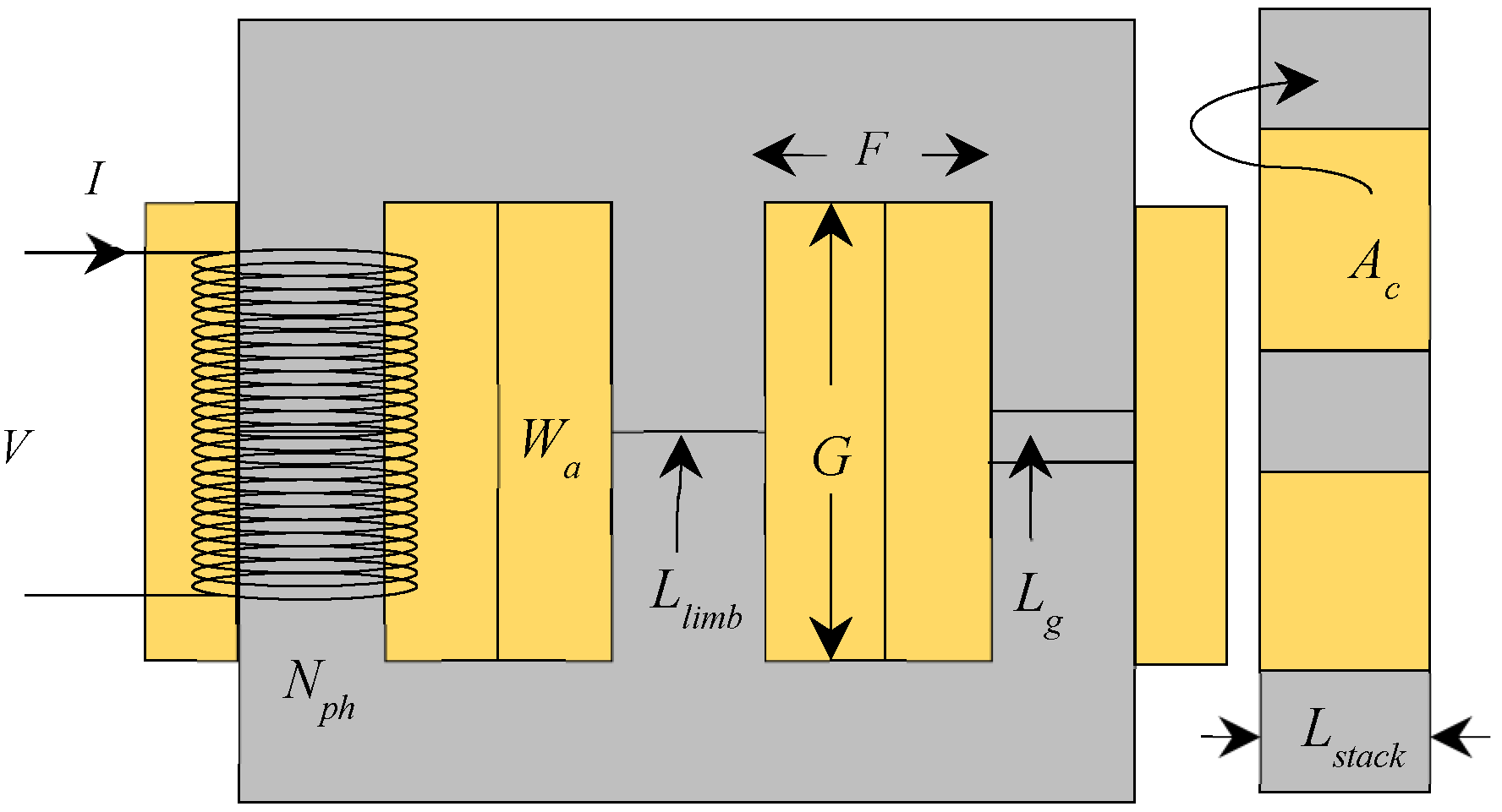
2.1. Expression for Area Product

The area product approach is the most common practice to design and size the inductor. The expression for area product can be obtained from the voltage induced on the inductor terminals [1,11]. The area product for a single phase system is given by Equation (1),
A c . W a = A p , 1 p h = V r m s I r m s K f K w B p e a k J r m s f s
For a 3-phase inductor, the area product will be different from the one indicated in Equation (1). Since the window utilization is half for each coil, the window area is different.
A p , 3 p h = 3 A c . ( W a 2 ) = 1.5 A p , 1 p h
Referring to Equations (1) and (2) and Figure 1, A c is the cross-sectional core area, W a is the window area, V r m s is the root-mean-square voltage induced across the inductor coil, I r m s is the root-mean-square current flowing through the coil, K f is the copper fill factor, K w is the waveform factor, B p e a k is the maximum flux density required in the core, J r m s is the root-mean-square current density of the conductor, and f s is the frequency of the inducted voltage across the coil. Equation (1) can be rewritten as Equation (3).
A c . W a = A p , 1 p h = 2 π I r m s 2 L s y n c h K f K w B p e a k J r m s
where L s y n c h is the synchronous inductance of an inductor, which can be obtained by using Equation (4),
L s y n c h = L ± L m
where L m is the mutual inductance and L is the self-inductance of inductor’s coil. Referring to Equation (3), it is clearly seen that the area product does not depend on the frequency of the induced voltage. However, the magnetic losses are proportional to the square of frequency. Therefore, while sizing an inductor, for high frequency (kHz to MHz) applications, it is essential to consider the magnetic flux density, which must be a lower value compared to that of the low frequency (Hz to kHz) inductor design [12,13]. “Assuming that the frequency in the design specification is modified from 100 Hz to 1 MHz. In this case, we pick the same iron core as that of 100 Hz which will result in unacceptable output from efficiency point of view, as the core loss will now increase by 52 times. As a result of this, the maximum flux density should be reset to a lower value, which necessitates trial-and-error-efforts” [12].

2.2. Typical Inductor Requirments & Sizing Constraints

As can be seen from Equation (3), the factors such as maximum magnetic flux density, frequency of the induced voltage, conductor’s current density, and the fill factor all have an impact on the inductor’s area product, i.e., the electrical parameters equating the physical parameters of an inductor. The window area W a implies the current conduction capabilities of an inductor, whereas the core area A c indicates the flux conduction capabilities. Equation (3) clearly indicates that the area product is inversely related with the maximum operating flux density in the core and the peak or RMS current density of a conductor. The current density is limited by thermal class of the wire insulation, whereas magnetic flux density in the core is limited by the material saturation. Selecting the high strength materials (i.e., operating an inductor with high current and flux densities) will result in a lower area product and hence lower overall inductor mass and volume [11,14].

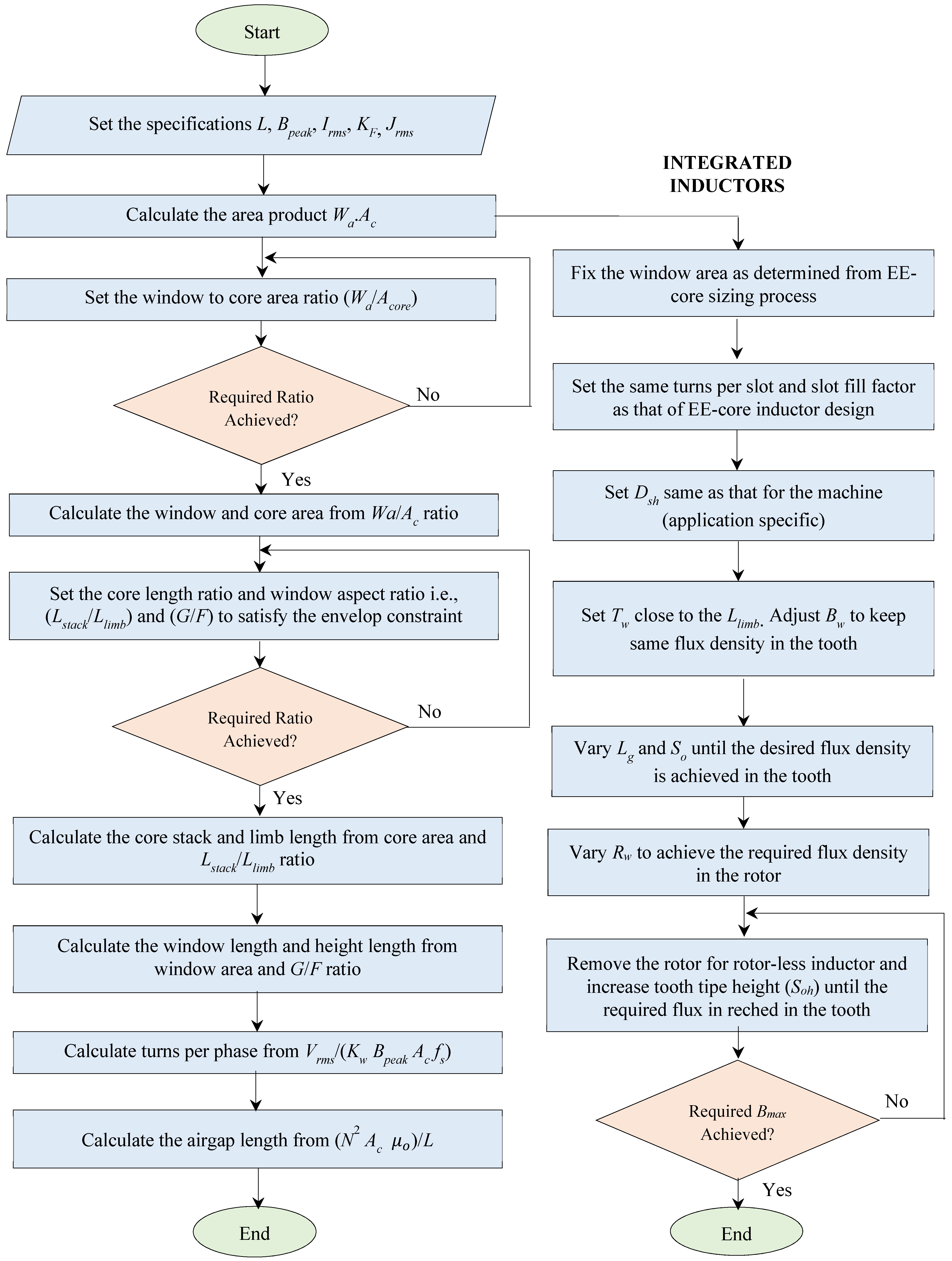
2.3. Inductor Sizing

The area product approach is a common practice to adopt in order to size the inductor. This section explains how the area product equation discussed in the previous section can be used to size both the traditional and integrated inductor, originally introduced in [4].

2.3.1. EE-Core Inductor

The layout of traditional EE-core inductor and its sizing algorithm is illustrated in Figure 1 and Figure 2 respectively. The factors that greatly influence the size of the inductor is the apparent power handling capability which is proportional to the product of core and window area as indicated in Equation (2). In order to compute the area product, the specifications such as window fill factor, maximum flux density, root-mean-square current, root-mean-square conductor’s current density, and required inductance must be specified. To set the window and core dimensions (G, F, Lstack and Llimb), the window aspect ratio (G/F) and core length ratio (Lstack/Llimb) are introduced. Keeping the low window to core area ratio help maintains the fringing flux at minimum level as suggested in [11,14]. Based on the core manufacturer, the value of window aspect ratio typically varies between 3 and 4. The value of core length ratio is application specific based on the volume and footprint available. Subsequently, based on the specified voltage across the inductor, the turns per coil or phase must be determined. Finally, the required inductance of an inductor is calculated through the equation of the air gap.
To avoid design discrepancies, the fringing flux needs to be taken into account. Fringing flux occurs at the airgap, it is the effect of the magnetic flux spreading out across the air gap, leaving and re-entering the magnetic core away from the air gap surface. This effect reduces the overall reluctance of the magnetic circuit, thereby producing higher inductance as compared to the designed value, which could drive the core into premature saturation. Furthermore, if the fringing flux is strong enough, it will induce the eddy currents in the nearby conductors, resulting in additional losses and localised heating [2]. Since the fringing flux reduces the overall reluctance of the magnetic path, the inductance increases by a factor “F” to a value greater than the designed one. The fringing factor is given by [11,14]:
F = 1 + L g A c l n ( 2 G L g )

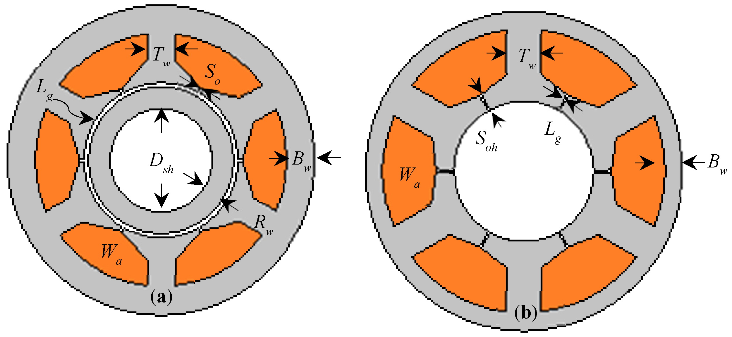
2.3.2. Integrated Inductors

The layout of integrated inductors are shown in Figure 3, whereas it’s sizing algorithm, which converts traditional EE-core inductor into integrated one, is shown in Figure 2. For both motor-shaped integrated inductors i.e., rotational inductor (Figure 3a) and rotor-less inductor (Figure 3b) windows area (Wa) kept same. The tooth width (Tw) is chosen as Llimb of traditional EE-core inductor. This is correct for the 6-slot inductor. However, whilst designing an inductor with more than 6 slots, the tooth width will be readjusted in order to maintain the overall core area. The back iron width (Bw) is varied in order to maintain the same level of flux density in the back of the core. The slot opening (So), air gap length (Lg), and the rotor width (Rw) are then adjusted so that the required level of flux density (Bpeak) is achieved, both back iron and stator tooth.
For the motor-shaped rotor-less inductor, the rotor needs to be detached and removed. To keep the uniform flux density (i.e., specified one—generally selected near the knee point on the BH curve of a given core material), the slot opening height (Soh) is increased. It is important to note here that, due to removal of the rotor, the physical air gap between the stator and the rotor is absent. Therefore, the inductance of the magnetic circuit is only controllable via slot opening height.

2.3.3. Inductor Sizing Using Simulation-Driven Approach

Inductors can be sized by using simulation-driven approach such as genetic algorithm (GA) and particle swarm optimisation. The GA is well suited to solve the problems where the decision variables are discontinuous, like transformers, inductors, and electric motors or generators, and is to be considered as the best tool to find an optimal solution, in the recent past [15,16,17,18]. The GA is a proven technique to solve both unconstrained and constrained optimisation problems, based on the natural selection (i.e., the process that drives biological evolution). The GA repeatedly alters a population of individual solutions and at each step it randomly picks individuals from the existing population who act as parents and uses them to produce the children for the next generation. Over successive generations, the population “evolves” toward an optimal solution [17,18].
The procedure of GA optimisation algorithm is to find a vector Y = (y1, y2, …, yn), representing a set of design variables, each of them bounded by yimyinyin, i = 1, 2, 3, …, n, so that the objective function F(Y) is maximised or minimised, and a set of k constraints Gj(Y) ≤ 0, j = 1, 2, …, k, is satisfied [17,18].
Figure 4 shows a typical design environment to size the inductor by using a simulation-driven optimisation approach. Referring to Figure 1 and Figure 4, the input variables for the inductor can be considered as: core area, window area, and electrical loading, which is the product of inductor current and the number of turns per phase. The design environment typically consists of an optimisation approach such as multi-objective genetic algorithm or particle swarm optimisation followed by an inductor design tool or model, i.e., either finite element or analytical based.
The output variables will then include the performance dependent parameters of the inductor, such as synchronous inductance, current and voltage total-harmonic-distortion (THD), core flux density, conductor’s current density, copper and iron losses, efficiency, mass, and volume.
Design constraints must consider the inductor limitations, such as magnetic and thermal. Magnetic flux density, in the core, solely limited by the material saturation whereas, the current density is limited by thermal limit of the conductor which in turn influences the life of wire insulation. The saturation flux density of the core material usually varied from 0.3 T to 2.2 T, which is considered for materials such as ferrites, amorphous alloys, non-oriented silicon steels, cobalt-iron, and nickel alloys [11,19], whereas the current density of a conductor typically is considered to be 5–6 A/mm2 for an air-cooled system [11,20] and it can go up to 30 A/mm2 for a forced cooling system [21,22]. Therefore, it is possible to reduce the mass and volume of an inductor by adopting a high strength core material and an improved cooling system. However, both come with the expense of the additional cost, leaving a trade-off between the cost and weight.
The objective functions of the optimisation are application-specific and can be considered one or more than one output performance parameter. Typically, in an inductor design, overall mass (i.e., copper + core) needs to be minimised and inductance needs to be maximised, in order to increase the inductance-to-weight ratio followed by either reducing the overall losses or increasing the efficiency.

3. Structural Layout & Integration of Filter Inductors

3.1. Traditional Inductors

There is a wide range of core layouts that are being used in the engineering industry to manufacture the filter inductors, the layouts of which are shown in Figure 5. The traditional magnetic and non-magnetic cores for an inductor are air core, tape wound, powder, and laminated cores, the in-depth details of which can be found in [11,23].

3.2. Integrated Inductors

Traditional motor drives have been in use for many years which utilises the conventional non-integrated passive inductors as shown in Figure 5. The power electronics and drive industries are shifting more towards the concept of integration (i.e., to integrate passives within the motor-drive) to gain the benefits such as cost-effective solutions, mass and volume reduction, and fewer construction process. The filter inductors have been integrated in many ways which consist of inductor integration inside the machine and integration in the traditional inductor cores.

3.2.1. Integration within the Machine’s Envelope

There are many case studies reported in the literature aiming to achieve the concept of integration where passive components are integrated within the motor-drive system. In [3,4,24,25,26], perspectives are presented on the integrated filter inductors that encourage the drive integration on a system level, as discussed below.

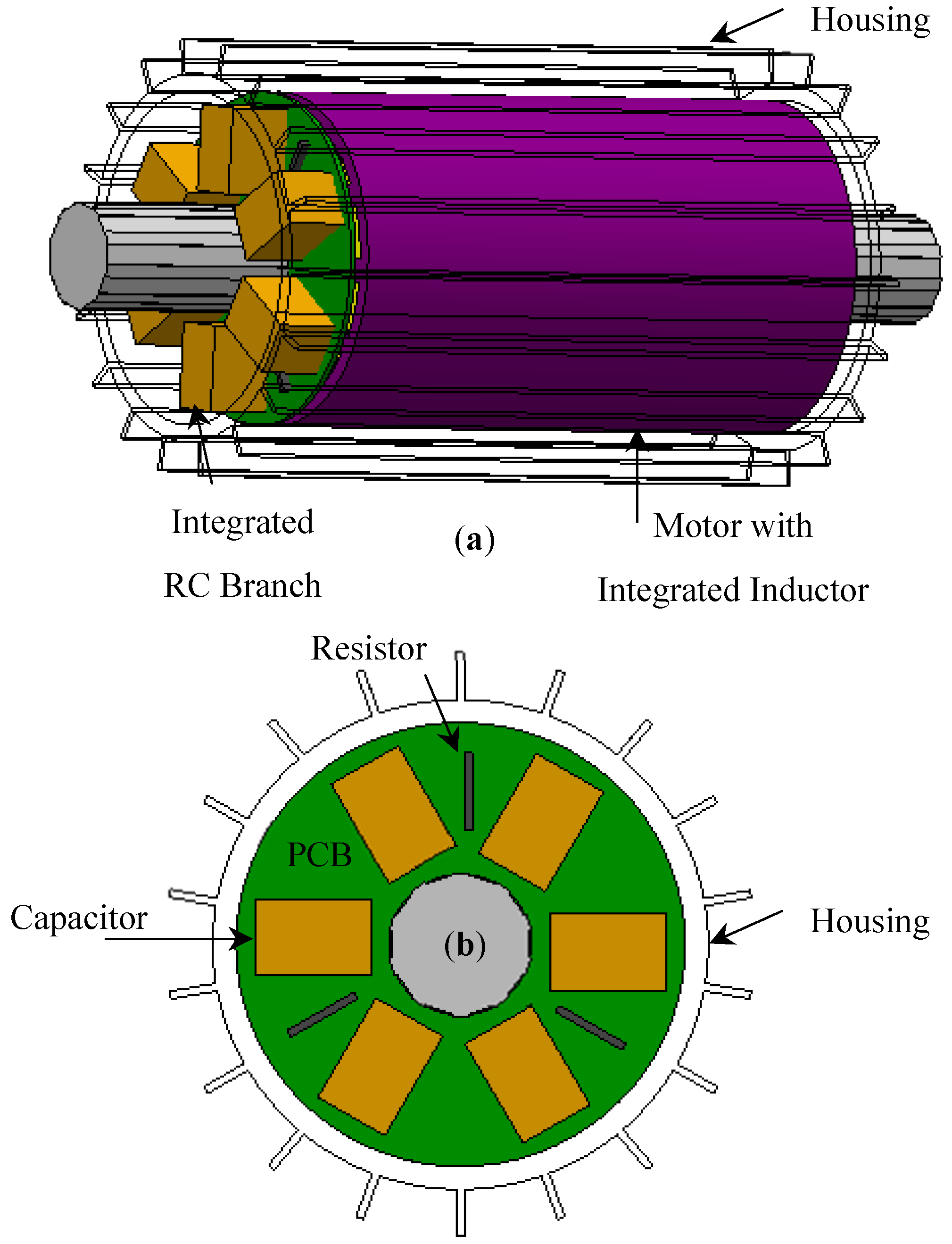
Motor with Integrated Output Filter Inductor

In [3], a new approach is introduced where the integrated inductor is presented for permanent magnet synchronous motor drives, at the inverter output. The paper uses the in-built motor inductance as the filter inductance, instead of sizing a discrete inductor as shown in Figure 6. The motor with integrated filter inductor (Figure 6b and Figure 7) does not have a discrete filter inductor as opposed to the motor-drive system shown in Figure 6a. The motor is operating at a speed of 2.1 kRPM and load of torque of 1.50 Nm. The motor has total 92 turns per phase and is split into two branches, i.e., filter branch and motor branch as illustrated in Figure 7. Each branch has the inductance of 1.3 mH with its corresponding 46 turns representing a single phase of the motor. A1, B1, and C1 belong to the filter branch, whilst A2, B2, and C2 represent the motor branch. The authors have suggested to tap the filter branch, which is to be determined based on the requirement of filter inductance. In this case, coil turns for the filter branch will be modified, with the aid of tapings, as per required inductance and the outstanding turns, which remain from the total coil turns, must be added to the motor branch.
Table 1 and Table 2 shows the FE based analysis which compares the performance of a traditional motor-drive system (i.e., with EE-core inductor) and integrated motor-drive system, fed through a voltage source inverter. The power losses, mass, and size of the inductor have been eliminated from the system in the integrated motor-drive. Furthermore, the effect of phase shift between the filter and motor branch currents on the mean electromagnetic torque is significantly small and can be neglected in the comparative study.
The torque ripple, on the other hand, is comparatively higher in the integrated motor-drive system due to the presence of ripple component (i.e., the frequency at which semiconductor device switches) in the filter branch. The experimental validation of the motor with an integrated filter inductor is presented in [23]. Figure 8a,b shows the FFT of the motor voltage and current for the motor with an integrated filter inductor and the motor with an external (i.e., traditional EE-core) filter inductor respectively. As can be observed from Figure 8, the filtering effect of the motor with integrated filter inductor and the motor with external inductor are alike, since the inductance seen by the inverter terminals is same, in both the motor-drive systems. The magnitude of current ripple at 20 kHz, seen from the motor terminals, is 7.9 mA and 8.1 mA for the motor with integrated and external inductors, respectively. The experimental results show that the half of the motor winding sees the filtered voltages and currents, which reduces the high gradient voltage stress and high frequency losses in half of the motor windings, without using any external inductor.

Motor-Shaped Inductors

The way traditional filter inductors are designed and sized is transformed in [4]. The concept of motor-shaped inductors was introduced in this article. This provides two novel integrative options for passive filter inductor: motor-shaped rotational inductors and rotor-less inductors as shown in Figure 9. The motor-shaped rotational inductor is different from the traditional filter inductor in such a way that it has the stator and rotor like electrical machines but without permanent magnets, rotor windings, or saliency. The motor-shaped rotor-less inductor has only a stator with extended slot-opening area. Both rotational and rotor-less inductor design are integrated axially inside the motor housing which resulted in a shared cooling system, as shown in Figure 9. As the motor-shaped inductor uses the same cooling system as that of motor or generator, it can be operated with a higher current density that would result in reduced overall size and mass of the inductor. The iron losses were reduced in the rotational inductor by rotating its rotor at synchronous speed. This makes it appropriate for application as the inverter output filter. On the other hand, the rotor-less inductor design is proposed to use as high-power line inductors or isolation transformers.
The concept of a rotational inductor, to reduce the iron losses through a rotor magnetic path, was validated through a finite element analysis. The loss analysis has been per-formed by rotating the rotor at synchronous speed and when the rotor is at standstill. At one point in the rotor, the X and Y components of magnetic flux density were analysed and converted into the d-q reference frame. The d component of the rotor flux density is displayed in Figure 10 and the q component of the rotor flux density is negligible. The iron loss through the rotor magnetic path is minimized, as the rotor flux density is constant with only a small ripple produced when the rotor is rotating at synchronous speed. This ripple is caused by the harmonics due to the stator slots.
On the other hand, when the rotor is stationary, the flux density changes sinusoidally over time. A comparison between motor-shaped inductors and traditional EE-core inductor had been made in relation to the total losses, AC resistance and its related volume and weight. For this case study, it is identified that, at fundamental frequency, the iron and copper losses in a rotational inductor are reduced by 22.5% and 45.3%, respectively. When compared to the EE-core inductor, overall losses at fundamental frequency are reduced by 26.1%. The iron and copper losses in a rotor-less inductor are reduced by 3.9% and 45.3% at the fundamental frequency. In comparison to the EE-core inductor, the total losses are reduced by 10.4% at the fundamental frequency. On the other hand, in rotor-less and motor-shaped rotational inductor, AC resistance is drastically reduced by 73.8% at switching frequencies of 10, 15, and 20 kHz. In [1], the concept of rotational inductor is experimentally validated, and a comparison has been made with a traditional EE-core inbuilt inductor and commercially available inductor in terms of power loss, weight, and volume. For the concept validation of integrated rotational inductor, 12 slots 2 poles single layer distributed winding is selected. The tests were conducted on 3-phase induction motor drive (as shown in Figure 11) rated at 49 kW, 20 kRPM which is suitable for validating and measuring the required performance of the rotational inductor whilst spinning the induction motor at no load. The rotor of rotational inductor is coupled with the shaft of the induction motor whereas, the stator is supped by programmable AC power source.
When the rotor is standstill and rotating, the rotational inductor is tested at various supply frequencies. At standstill and when the rotor was rotating at supply frequency of 100 Hz, 200 Hz, and 300 Hz, the total inductor losses and peak inductor current of 18 A were measured. Figure 12a shows the measured inductor loss at 18 kRPM and 300 Hz, showing that the inductor losses decrease as the rotor speeds up to its synchronous speed. As the rotor speed increases to the synchronous speed, the percentage of loss reduction also increases. This is because the magnetic field through the rotor of the inductor is rotating synchronously with the rotating magnetic field induced by the stator currents. The difference in core losses at 300 Hz with respect to the speed of rotor, in both positive and negative directions, is shown in Figure 12b. After subtracting the 3-phase copper losses, the iron losses were plotted against the rotor speed. The iron losses are minimum as expected at the synchronous speed, however this increases when slip value increases in the counterclockwise direction. Where the slip is at 2, the highest point of loss occurs when the rotor is rotating at synchronous speed in the counterclockwise direction.
The comparison of total loss-to-inductance ratio between a traditional rational inductor and EE-core is illustrated in Table 3. It is observed that as the motor speed ups to 18 kRPM the total loss reduction is increased and the total loss to inductance ratio is reduced. The loss-to-inductance ratio is higher as the inductance of the EE-core is lower, in comparison to the rotational inductor with reduced iron loss. At a rotor speed of 12,000 rpm and 18,000 rpm, a reduction of 8.9% and 22.7% is obtained. On the other hand, at 6000 rpm, due to the reduced rotor speed of the rotational inductor, the EE-core gives a lower loss-to-inductance ratio.

High Current Density Rotor-Less Inductor

Figure 13b represents the design of an integrated rotor-less inductor, for an aerospace starter-generator application (45 kW), as presented in [20]. In terms of total volume and weight, a comparison is made to observe the impact of high current density on an inductor against the traditional EE-core inductor. To size both the inductors, the area product approach method was used, and the design parameters were validated using FEA. A significant reduction in the total volume and weight was observed during the comparative analysis between the integrated inductor and traditional EE-core, presented in Table 4. When compared to the traditional air-cooled EE-core inductor, the total volume of the integrated inductor is reduced by 52.7% and the total weight is reduced by 55.4%, as shown in Table 4.
On the other hand, both the weight and volume of the combined system with an integrated inductor are significantly reduced by 25.5% and 29.1%, respectively. However, this reduction comes at the expense of excess 0.9 kW, due to the higher current density (assumed in the design phase) of the integrated inductor as opposed to the EE-core inductor. This increases the stator winding loss, thereby generating heat inside the inductor’s windings that is taken out of the starter-generator by the existing cooling system, where the inductor’s stator is flooded with the engine oil. In [27], a thermal design investigation of an integrated inductor system and a combined starter-generator is presented where complete integration is achieved from thermal and physical points of view.
As both machine and inductor share the same cooling arrangement; a comparison was made between the performance of a direct and an indirect cooling option. The direct cooling arrangement, as shown in Figure 13c, based on a semi-flooded design results in a temperature reduction of up to 90 °C in the most important components in contrast to the indirect cooling method. The results showed that the shared semi-flooded arrangement proposed keeps the operating temperatures below the maximum permissible limits (i.e., 134.5 < 180 °C), leaving a significant safety margin in case of overpower conditions or short circuit failure conditions.

Integrated Inductor Wound on the Stator Back Iron

The design of an integrated filter inductor that is required for power factor correction application is presented in [24], as shown in Figure 14a. The author utilises the motor magnetic structure to create an integrated filter inductor. The stator back iron of the switched reluctance motor is brought into use for a boost power factor correction application. To increase the stator back iron, the stator laminations were modified in the paper. With this alteration, the motor outer diameter was increased, which resulted in an increase in the overall size and weight of the motor. However, the integrated inductor design does not interact with the magnetic field of the motor itself.
The integrated filter inductor as shown in Figure 14a is approximated to an inductor geometry as shown in Figure 14b for simplicity. The inductor design was presented for a 1 kW motor drive with a target inductance of 15 mH. Four sections of integrated inductor located at the back of stator core was based on ¾ hp induction motor with M-19 electrical steel. The stack length is fixed from motor dimensions, whereas the rest of the sizing dimensions were calculated using the reluctance equivalent circuit analysis. To ensure the core material is operating in the linear region of its B-H characteristics, the airgap length and the core area were varied iteratively, in order to achieve the desired inductance.
The complete stator back iron is used as a magnetic component for one or more discrete inductors or transformers in other publications [25,26], as shown in Figure 15. This is achieved by integrating a toroidal winding in the back of the stator core, which drives the alternating magnetic ring flux. This ring flux shares the back iron with main motor flux. The ring flux always travel in one direction, whereas the main flux has as much flux going anti-clockwise in the back of the core as is going clockwise. Therefore, ring flux, at some point, will increase the MMF drop in the core and vice versa. The presence of ring flux due to inductor winding will not affect the main motor flux passing the airgap if the core is operating in the linear region of its B-H characteristics. The number of turns, according to the author, must be an integer multiple of twice the number of pole-pairs. Even though there are ring conductors in the bottom of every stator slot, there can be as few as two toroidal turns in a 2-pole motor, regardless of the number of stator slots.
The application of sinusoidal output filter is considered for a 2-pole, 24 slots inductor motor. The induction motor is operating with 240 V RMS phase-phase voltage with 0.85 power factor at full load conditions of 6.5 A RMS. The cross-sectional area of the toroidal winding is 2880 mm2 with mean length of 450 mm. The toroidal winding is divided into 3 separate axial portions, one for each phase. With a maximum allowable toroidal MMF and a peak phase current of 9.2 A, the maximum allowable turns are 24 (which is one turn per stator slot). With 24 turns, inductance of 0.43 mH is achieved per phase. Furthermore, there are drawbacks associated with this approach whilst incorporating toroidal inductor into the motor. This includes a loss of slot-space to accommodate toroidal windings, the need for extra volume between stator core and the motor frame for toroidal windings, along with the manufacturing complications associated whilst inserting the toroidal windings into each portion of the core.
The integration of a grid side passive LCL filter into the stator back iron of a permanent magnet synchronous machine produces high power density, according to the Authors of [7,28,29,30,31]. As shown in Figure 16a, both inductors (L1 and L2) are wound into the double slot machine’s outermost slots. The proposed integrated inductor is iteratively optimised in terms of iron and copper weight and compared with the conventional separate inductor. The cross-coupling of magnetic fields between the main machine and filter windings is avoided by placing the filter inductors on the outermost slots. This is attained by adopting a different number of poles for the filter winding than the torque producing motor (main) windings. Magnetic poles are balanced or unbalanced depending on the different pole number combination in the filter windings and the main machine.
As a result, the main machine and filter winding pole numbers must be separated by a multiple of two pole pairs. This allows both magnetic fields to rotate at different speeds, resulting in minimal flux linkage between them. The method is verified using FEA by providing both windings simultaneously at different supply frequencies. The results presented the minimum cross-coupling between the main winding and the filter windings which is responsible for the production of torque. Figure 16b shows the winding arrangement of the machine with integrated grid side LCL filter that illustrates the main motor winding is connected at the inverter output terminals and the integrated inductors (L1 and L2) winding is connected between the grid and the rectifier input terminals. A 3-phase 12s/8p permanent magnet synchronous machine is selected which gives 12 main windings, each phase has 4 single layer concentrated windings connected in parallel. On the other hand, 24 integrated inductor windings are wound on the outermost slots, and each phase has 8 double layers concentrated windings connected in series. The integrated windings are further divided into the grid side and drive side inductor winding with 4 coils each connected in series.

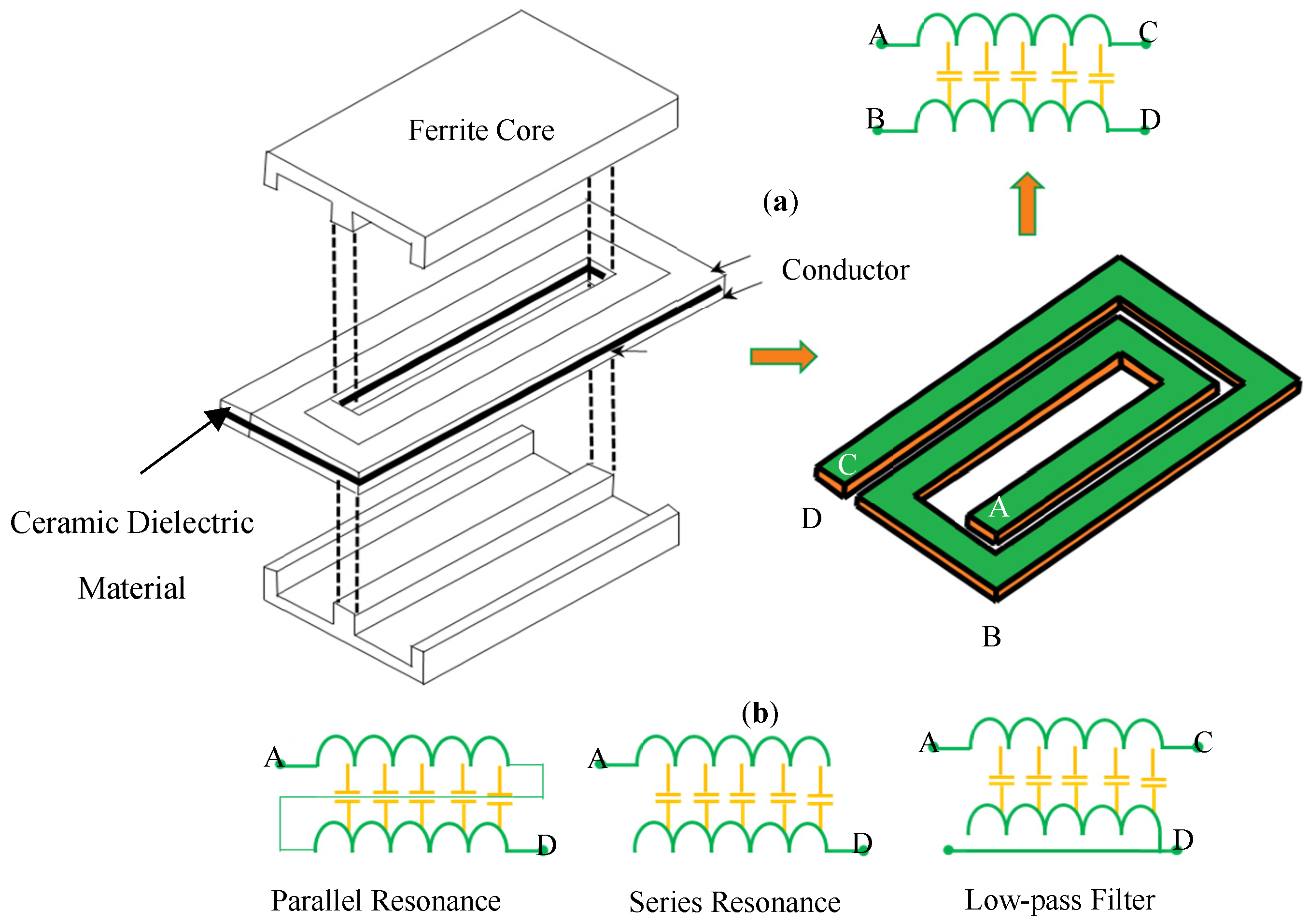
3.2.2. Integration within the Traditional Cores

Article [32] designed a passive DC-link inductor to reduce the grid side harmonics, DC-side voltage ripple, current stress of the DC link capacitors, and rectifier side diodes.
As shown in Figure 16a, the design of two independent DC-link inductors is switched to an integrated structure on a single magnetic core. As represented in Figure 17b,c, the inductor can be integrated by directing the flux either in the outer leg or the middle leg. Depending on the target specification and design specification, all inductor designs can be built to have the same amount of inductance, as shown in Figure 17a–c.
Various studies have taken place in order to integrate both capacitors and inductors into the same component [8,9,33,34,35,36,37,38]. To integrate the capacitance in the same magnetic component as the inductor, the principle of electromagnetic integration is used. A planar LC filter that is integrated with alternating layers of conductors, insulation, magnetic material, and dielectrics was observed in [33,34,35,36,37,38], as represented in Figure 18. The LC winding is a dielectric substrate with conductor windings directly deposited on both sides, thus resulting in a distributed inductance and capacitance structure, as shown in Figure 18a. By properly connecting the four terminals A, B, C, and D of the LC winding, a different equivalent structure is possible as an equivalent LC series resonator, parallel resonator, or low pass filter, as shown in Figure 18b.
The same principle of [18,19,31,32,33,34] is applied in article [8,9] for EMI filter applications. By introducing a dielectric layer between the windings, the capacitance in the windings increased. The distributed capacitance is implemented in a traditional way where the anode and cathode foil are etched with aluminium oxide dielectric layers. The inductor is constructed using the cathode and anode aluminium foils of the capacitor to implement the windings, and as represented in Figure 19a the foil windings are wound around. As presented in Figure 19b, the inductor windings are packed in a can, which has a hole in the middle for the magnetic core. This work has been extended for high power density applications and was put through electrolytic capacitor technology in a 2.2 kW motor drive to integrate the DC side smoothing capacitor. This work showed that the volume of the integrated EMI filter decreased considerably by 45% in comparison to the discrete EMI filter, whilst meeting the EMC standards.

3.2.3. Integrated Inductor on Power Module Substrate

Inductors integrated onto the power modules substrate are presented and discussed, in this section. The advantage of having this approach is that the windings can be constructed from the same substrate materials that will allow a direct conduction path from the windings to the outer surface and onto the thermal management system. This will result in an increase in thermal efficiency, allowing for higher current densities in inductors than is usually possible.
A new integration methodology is investigated in [39] for a standard basic power cell (SBPC) circuit, with the aim of integrating an inductor on power module substrates together with the switching devices, in order to improve its power density and thermal management. The proposed concept consists of bonding copper U-shapes, as shown in Figure 20a, representative of individual turns of the windings on the substrate that offer an enhanced thermal exchange between the inductor and the cooling system, resulting in an increased current density for a given power level. From a construction point of view, the inductor and the power devices are bonded on the same aluminium nitride (Al N) direct bonded copper (DBC) substrate that results in a uniform thermal distribution across the inductor coils as opposed to the traditional inductors where the only input and output terminals are electrically and hence thermally connected to the substrate. An FEA based comparative study of thermal distribution was carried out for two cases: (1) when a solid solenoid is used and only the first and the last turns are bonded to the copper traces of the DBC whereas, the rest of the inductor is laid on the substrate, (2) when individual U-shapes are bonded onto the substrate. The study showed a uniform temperature distribution across all the turns when the inductor is constructed with individual copper U-shapes bonded on the copper traces, when compared to the case 1. In publications [40,41], the inductors are machined from a Cu bulk to create the desired winding shape where one side is bonded on DBC substrate so that the inductors and the power switches shares a common cooling system. However, the disadvantage of this approach is the difficult manufacturing process for copper windings, which has been shown to be costly and inconsistent. Another article [42] investigated the integration of high current density inductor onto a double side cooled (i.e., sandwich structure) power module substrate, as shown in Figure 20b. From a construction point of view, the inductors are integrated in between the two DBC ceramic substrates that form the sandwich module where two DBC ceramic substrate tiles are directly cooled using jet impingement. The module is usually cooled on its top and bottom sides, providing a larger amount of cooling to the devices. Thus, a lightweight and compact module can be achieved. Both FEA and experimental studies were carried out at room temperature when the inductor current was increased from 0 to 100 A, with a maximum current density of 100 A/mm2. The peak temperature of the inductor was recorded with respect to the applied current, as illustrated in Figure 20c. The results showed that the inductor’s peak temperature is changing approximately to the current squared. Another observation is that the current density of 100 A/mm2 is achieved with only a 60°C temperature rise.

4. Integration of RC Branch and Capacitor Technologies for Integrated Filters

4.1. Integration of RC Branch

The integration of the RC branch (i.e., filter capacitance and damping resistance), as shown in Figure 6b, inside the motor’s housing can be achieved by mounting and arranging the 3-phase capacitors and resistors on the PCB [10,28]. The conceptual example shown in Figure 21 can consist of 3 (or multiple of 3) capacitors to be integrated inside the machine’s enclosure. The choice between different technologies of capacitors, considering integration application, depends on the various factors, such as cost and temperature limitations. The details of each available integrated technology currently being used for the filter capacitors are enlisted in the next section.

4.2. Capacitor Technologies for Integrated Filters

Compared to other passive components, the cost and size of an electronic system is dominated by the capacitors utilised in the system [43]. Integrating a capacitor as part of an integrated filter circuit will require the chosen capacitor fulfilling both spatial and capacitance requirements. For a low pass filter, a large capacitance is required. However, the size of the capacitor (plates) increases with capacitance. This is particularly challenging, especially with the restricted space in the machine enclosure. Capacitors are also temperature dependent due to the thermal limitations of many common capacitors. This causes some capacitors to lose charge due to leakage currents occurring at high temperatures [40]. The capacitor technologies available for integrated filters are outlined below:
  • Film capacitors
  • Electrolytic capacitors
  • Ceramic capacitors
  • Electro-chemical double layer (ECDL)

4.2.1. Film Capacitors

Film capacitors are very scalable with ratings ranging from a few nanojoules to hundreds of kilojoules per unit. They also represent the most flexible option in terms of device geometry compared to other capacitor technologies [44,45]. These features are particularly attractive in an integrated application, especially where space is limited. High efficiencies due to a low equivalent series resistance (ESR) (about 1%) and a low dissipation factor (1%) are also some of the potential benefits of film capacitors. They also possess high working voltage operation (up to 100 kV), high energy densities [46,47], and are polarity independent (bipolar operation). Despite these attractive benefits, the capacitance per volume of film capacitors is low compared to other capacitor technologies. The operating temperature of film capacitors is also a disadvantage with maximum operating temperatures less than 170 °C [48]. Theoretical operating temperatures are quoted at 220 °C, suggesting the technology is close to maturity. High temperature operation is vital in integrated filters, especially the novel concept proposed in this paper. Film capacitors, despite their capacitance limitations, can offer a realistic option in integrated filter applications due to their high efficiency, high operating voltage, and geometry flexibility.

4.2.2. Electrolytic Capacitors

The electrolytic capacitor offers the highest energy densities of the four capacitor technologies (up to 1 J/cm3). The most popular choices in this range remain aluminium electrolytic capacitors and tantalum electrolytic capacitors. Tantalum electrolytic capacitors provide a wider operating temperature range and smaller size compared to aluminium electrolytic capacitors. However, a greater capacitance and cheaper option is offered by aluminium electrolytic capacitors in comparison to Tantalum capacitors [49]. Both options offer significantly higher capacitance compared to other conventional capacitor technologies (capacitances from 1 μF to 2 F) [50,51]. Despite the aforementioned benefits of electrolytic capacitors, they exhibit relatively high ESR, high equivalent series inductance (ESL), and high dissipation factor, especially at high frequencies [51]. However, recent technological advancements have led to the production of aluminium and polymer tantalum and capacitors with very low ESR and ESL [49]. It also has a low operating voltage rating (about 600 V). With a maximum operating temperature of only about 120 °C, its use in high temperature operation applications is challenging [50]. It also has the lowest AC current ratings of the stated capacitor options and is polarity dependent thus restricting its applications to DC circuits [45]. At high temperatures, electrolytic capacitors are also susceptible to thermal degradation, a heat triggered electrochemical reaction, reducing the overall lifetime of the capacitor. This is particularly problematic in integrated filter applications as reliability is greatly reduced and maintenance costs are increased due to component replacement [52,53,54]. Although tantalum electrolytic capacitors offer a high capacitance and small volume, properties beneficial in integrated filter applications, the operating temperature limitations and short life cycle compared to other capacitor technologies makes it a less favourable capacitor choice in this application.

4.2.3. Ceramic Capacitors

The ceramic capacitor possesses high power densities due to their small size compared to other capacitor technologies. It also provides low to moderate size capacitance ratings. Its major advantage compared to other capacitor options are its high temperature operating capability and relatively high AC current ratings [55,56,57,58]. Typical operating temperatures of ceramic capacitors reach up to 200 °C [54]. However, specialised high temperature ceramic capacitors have been noted to reach temperatures up to 250 °C [59]. In integrated filter applications where high temperature operation and small size are critical, ceramic capacitors prove a suitable candidate for utilisation. The high cost of ceramic capacitors compared to other conventional capacitor technologies is one of the major drawbacks [59]. They are also not as robust as film or electrolytic capacitors, especially in vibration prone environments [60,61,62] his is due to the brittle nature of the ceramic material. This poses reliability questions, especially concerning the mechanical stability in integrated filter applications.
The recently released “CeraLink” ceramic capacitors [63,64,65] is of interest to extend the scope of multi-layer ceramic capacitor for DC-link applications. The formulation contains a lead lanthanum zirconate titanate ceramic as dielectric material. It offers higher capacitance values at voltages close to the DC-link due to its anti-ferroelectric behaviour and strong positive bias [62,63]. Moreover, its ESR decreases with frequency and temperature, which allows efficient operation at high temperatures up to 150 °C and high switching frequencies up to several MHz [63]. With this technology, the capacitance density of 2 to 5 μF/cm3 can be achieved with low ESL of 2.5–4 nH. High thermal robustness allows these capacitors to be placed very close to the power devices [65], making them a suitable solution for integrated motor drives.

4.2.4. Electro-Chemical Double Layer (ECDL) Capacitors

ECDL capacitors are not conventional capacitors and are more akin to electrochemical batteries. Often known as “super-capacitors” or “ultra-capacitors”, ECDL capacitors possess a high power and energy density, a middle path between capacitors and batteries [66,67]. Their typical applications include transport and high-power applications where high-power densities are required [68]. The large size of ECDL capacitors, high cost, and high self-discharging rate [69] compared to other capacitor options make ECDL capacitors a poor option for integrated filter applications.

5. Conclusions

Reducing overall system mass and volume has become a mandatory requirement for aerospace, marine, and automotive applications, in order to comply with the power density needs. These can be met by shifting towards integrated motor drive (IMD) systems. This paper has covered the design methods for both conventional and integrated inductors. The article subsequently reviewed the existing motor drives system with integrated passive technologies that aim to provide enormous benefits over conventional topologies, in terms of reducing mass, volume, losses, and to ease the manufacturing process. A method of integrating a filter capacitor and resistor is also proposed followed by the available capacitor technologies, which is suitable for integration purposes, alongside the pros and cons of each capacitor type.

Author Contributions

Conceptualization, M.R.K. and R.A.; methodology, M.R.K. and A.W.; validation, M.R.K. and C.P.; formal analysis, M.R.K., R.A. and G.L.C.; investigation, M.R.K.; resources, M.R.K. and R.A.; writing—original draft preparation, M.R.K. and R.A.; writing—review and editing, G.V., A.W., C.P., P.B.B. and G.L.C.; visualization, M.R.K. and P.B.B.; supervision, G.V. and C.G.; project administration, G.V. and C.G.; funding acquisition, G.V. and C.G. All authors have read and agreed to the published version of the manuscript.

Funding

This research received no external funding.

Institutional Review Board Statement

Not Applicable.

Informed Consent Statement

Not Applicable.

Data Availability Statement

Not Applicable.

Conflicts of Interest

The authors declare no conflict of interest.

References

  1. Khowja, M.R.; Gerada, C.; Vakil, G.; Abebe, R.; Odhano, S.A.; Patel, C.; Wheeler, P. Novel Motor-Shaped Rotational Inductor for Motor Drive Applications. IEEE Trans. Ind. Electron. 2020, 67, 1844–1854. [Google Scholar] [CrossRef]
  2. Walker, A.; Vakil, G.; Gerada, C. Novel Core Designs to Miniaturise Passive Magnetic Components. In Proceedings of the 2018 IEEE Transportation Electrification Conference and Expo (ITEC), Long Beach, CA, USA, 13–15 June 2018; pp. 644–649. [Google Scholar]
  3. Khowja, M.R.; Gerada, C.; Vakil, G.; Wheeler, P.; Patel, C. Integrated Output Filter Inductor for Permanent Magnet Motor Drives. In Proceedings of the Industrial Electronics Society, IECON 2016—42nd Annual Conference of the IEEE, Florence, Italy, 23–26 October 2016. [Google Scholar]
  4. Khowja, M.R.; Gerada, C.; Vakil, G.; Wheeler, P.; Patel, C. Novel Integrative Options for Passive Filter Inductor in High-Speed AC Drives. In Proceedings of the Industrial Electronics Society, IECON 2016—42nd Annual Conference of the IEEE, Florence, Italy, 23–26 October 2016. [Google Scholar]
  5. Lambert, S.M.; Mecrow, B.C.; Abebe, R.; Vakil, G.; Johnson, C.M.G. Integrated Drives for Transport—A Review of the Enabling Electronics Technology. In Proceedings of the 2015 IEEE Vehicle Power and Propulsion Conference (VPPC), Montreal, QC, Canada, 19–22 October 2015; pp. 1–6. [Google Scholar]
  6. Wu, S.; Tian, C.; Zhao, W.; Zhou, J.; Zhang, X. Design and Analysis of an Integrated Modular Motor Drive for More Electric Aircraft. IEEE Trans. Transp. Electrif. 2020, 6, 1412–1420. [Google Scholar] [CrossRef]
  7. Mohamed, M.A.; Lambert, S.M.; Mecrow, B.C.; Atkinson, D.J.; Smith, A.C. An electrical machine with integrated drive LCL filter components. In Proceedings of the 8th IET International Conference on Power Electronics, Machines and Drives (PEMD 2016), Glasgow, UK, 19–21 April 2016; pp. 1–6. [Google Scholar]
  8. Popovic, J.; Ferreira, J.A.; Gerber, M.B.; Konig, A.; Doncker, R.d. Integration technologies for high power density power electronic converters for AC drives. In Proceedings of the International Symposium on Power Electronics, Electrical Drives, Automation and Motion, Taormina, Italy, 23–26 May 2006; pp. 634–639. [Google Scholar]
  9. Popovic-Gerber, J.; Gerber, M.; Ferreira, B. Integrated filter in electrolytic capacitor technology for implementation in high power density industrial drives. In Proceedings of the 2008 IEEE Power Electronics Specialists Conference, Rhodes, Greece, 15–19 June 2008; pp. 2968–2974. [Google Scholar]
  10. Abebe, R.; Vakil, G.; Calzo, G.L.; Cox, T.; Lambert, S.; Johnson, M.; Gerada, C.; Mecrow, B. Integrated motor drives: State of the art and future trends. IET Electr. Power Appl. 2016, 10, 757–771. [Google Scholar] [CrossRef] [Green Version]
  11. Mclyman, C.W.T. Transformer and Inductor Design Handbook, 4th ed.; Taloy Francis Group: Idyllwild, CA, USA, 2004. [Google Scholar]
  12. Kazimierczuk, M.K.; Sekiya, H. Design of AC resonant inductors using area product method. In Proceedings of the 2009 IEEE Energy Conversion Congress and Exposition, San Jose, CA, USA, 20–24 September 2009; pp. 994–1001. [Google Scholar]
  13. Nijende, H.; Frohleke, N.; Bocker, J. Optimized size design of integrated magnetic components using area product approach. In Proceedings of the 2005 European Conference on Power Electronics and Applications, Dresden, Germany, 11–14 September 2005; p. 10. [Google Scholar]
  14. Mclyman, C.W.T. Magnetic Core Selection for Transformers and Inductors, 2nd ed.; Taloy Francis Group: Boca Raton, CA, USA, 2017. [Google Scholar]
  15. Goodrick, K.J.; Seo, G.-S.; Mukherjee, S.; Roy, J.; Mallik, R.; Majmunovic, B.; Dutta, S.; Maksimović, D.; Johnson, B. LCOE Design Optimization Using Genetic Algorithm with Improved Component Models for Medium-Voltage Transformerless PV Inverters. In Proceedings of the 2020 IEEE Energy Conversion Congress and Exposition (ECCE), Detroit, MI, USA, 11–15 October 2020; pp. 2262–2267. [Google Scholar]
  16. Schobre, T.; Ariztegui, R.G.; Mallwitz, R. Genetic Algorithm Based Multi Objective Optimization for Inductor Design. In Proceedings of the 2020 22nd European Conference on Power Electronics and Applications (EPE’20 ECCE Europe), Lyon, France, 7–11 September 2020; pp. 1–9. [Google Scholar]
  17. Ho, S.L.; Chen, N.; Fu, W.N. An Optimal Design Method for the Minimization of Cogging Torques of a Permanent Magnet Motor Using FEM and Genetic Algorithm. IEEE Trans. Appl. Supercond. 2010, 20, 861–864. [Google Scholar] [CrossRef]
  18. Hwang, C.; Lyu, L.; Liu, C.; Li, P. Optimal Design of an SPM Motor Using Genetic Algorithms and Taguchi Method. IEEE Trans. Magn. 2008, 44, 4325–4328. [Google Scholar] [CrossRef]
  19. Fernando, N.; Vakil, G.; Arumugam, P.; Amankwah, E.; Gerada, C.; Bozhko, S. Impact of Soft Magnetic Material on Design of High-Speed Permanent-Magnet Machines. IEEE Trans. Ind. Electron. 2017, 64, 2415–2423. [Google Scholar] [CrossRef]
  20. Khowja, M.R.; Gerada, C.; Vakil, G.; Quadri, S.Q.; Wheeler, P.; Patel, C. Design of an Integrated Inductor for 45kW Aerospace Starter-Generator. In Proceedings of the 2018 IEEE Transportation Electrification Conference and Expo (ITEC), Long Beach, CA, USA, 13–15 June 2018; pp. 570–575. [Google Scholar]
  21. Trentin, A.; Zanchetta, P.; Clare, J.; Wheeler, P. Automated Optimal Design of Input Filters for Direct AC/AC Matrix Converters. IEEE Trans. Ind. Electron. 2012, 59, 2811–2823. [Google Scholar] [CrossRef]
  22. Khowja, M.R.; Vakil, G.; Gerada, C.; Yang, T.; Bozhko, S.; Wheeler, P. Trade-off Study of a High Power Density Starter-Generator for Turboprop Aircraft System. In Proceedings of the IECON 2019—45th Annual Conference of the IEEE Industrial Electronics Society, Lisbon, Portugal, 14–17 October 2019; Volume 1, pp. 1435–1440. [Google Scholar]
  23. Khowja, M.R.; Gerada, C.; Vakil, G.; Patel, C.; Odhano, S.A.; Walker, A.; Wheeler, P. Novel Permanent Magnet Synchronous Motor with Integrated Filter Inductor, Using Motor’s Inherent Magnetics. IEEE Trans. Ind. Electron. 2020, 68, 5638–5649. [Google Scholar] [CrossRef]
  24. Nee, B.M.; Chapman, P.L. Integrated Filter Elements in Electric Drives. In Proceedings of the 2007 IEEE Vehicle Power and Propulsion Conference, Arlington, TX, USA, 9–12 September 2007; pp. 148–153. [Google Scholar]
  25. Garvey, S.D.; Norris, W.T.; Wright, M.T. The role of integrated passive components in protecting motor windings. IEE Proc.-Electr. Power Appl. 2000, 147, 367–370. [Google Scholar] [CrossRef]
  26. Nakajima, Y.I.; Mizukoshi, T.; Sato, Y.; Zushi, S.; Yusuke, Z. Ntegrated Capacitor Type Stator. U.S. Patent US 8,049,383 B2, 31 October 2011. [Google Scholar]
  27. Rocca, A.L.; Khowja, M.R.; Vakil, G.; Gerada, C.; Wheeler, P. Thermal Design of an Integrated Inductor for 45kW Aerospace Starter-Generator. In Proceedings of the 2020 IEEE Transportation Electrification Conference and Expo (ITEC), Chicago, IL, USA, 23–26 June 2020. [Google Scholar]
  28. Deng, X.; Lambert, S.; Mecrow, B.; Mohamed, M.A.S. Design Consideration of a High-Speed Integrated Permanent Magnet Machine and its Drive System, In Proceedings of the 2018 XIII International Conference on Electrical Machines (ICEM). Alexandroupoli, Greece, 3–6 September 2018; pp. 1465–1470. [Google Scholar]
  29. Deng, X.; Lambert, S.; Mecrow, B.; Mohamed, M.A.S.; Ullah, S. Winding connection solution for an integrated synchronous motor drive. In Proceedings of the 2017 IEEE International Electric Machines and Drives Conference (IEMDC), Miami, FL, USA, 21–24 May 2017; pp. 1–7. [Google Scholar]
  30. Mohamed, M.A.S.; Lambert, S.M.; Mecrow, B.C.; Deng, X.; Ullah, S.; Smith, A.C. Integrating the magnetics of an LCL filter into a high speed machine with pre-compressed coils. In Proceedings of the 2017 IEEE International Electric Machines and Drives Conference (IEMDC), Miami, FL, USA, 21–24 May 2017; pp. 1–7. [Google Scholar]
  31. Deng, X.; Mohamed, M.A.S.; Lambert, S.; Mecrow, B.C. Development of a High-Speed, Permanent Magnet, SiC-Based Drive with Integrated Input Filters. IEEE Trans. Energy Convers. 2020, 35, 863–874. [Google Scholar] [CrossRef]
  32. Vrankovic, Z.; Wei, L.; Winterhalter, C.; Hong, B.Y. The influence of the DC link inductor design on the rectifier voltage stress in an adjustable speed drive during a mains voltage surge. In Proceedings of the 2009 IEEE Energy Conversion Congress and Exposition, San Jose, CA, USA, 20–24 September 2009; pp. 3653–3659. [Google Scholar]
  33. Luo, F.; Robutel, R.; Wang, S.; Wang, F.; Boroyevich, D. Integrated Input EMI Filter for a 2 kW DC-fed 3-phase Motor Drive. In Proceedings of the 2009 Twenty-Fourth Annual IEEE Applied Power Electronics Conference and Exposition, Washington, DC, USA, 15–19 February 2009; pp. 325–329. [Google Scholar]
  34. Rengang, C.; Strydom, J.T.; van Wyk, J.D. Design of planar integrated passive module for zero-voltage-switched asymmetrical half-bridge PWM converter. IEEE Trans. Ind. Appl. 2003, 39, 1648–1655. [Google Scholar] [CrossRef]
  35. Rengang, C.; Shuo, W.; van Wyk, J.D.; Odendaal, W.G. Integration of EMI filter for distributed power system (DPS) front-end converter. In Proceedings of the IEEE 34th Annual Conference on Power Electronics Specialist, Acapulco, Mexico, 15–19 June 2003; Volume 1, pp. 296–300. [Google Scholar]
  36. Zhao, L.; Strydom, J.T.; van Wyk, J.D. Wide band modeling of integrated power passive structures: The series resonator. IEEE Trans. Power Electron. 2002, 3, 1283–1288. [Google Scholar]
  37. Lingyin, Z.; Strydom, J.T.; van Wyk, J.D. An alternative planar multi-cell structure integrated reactive module. In Proceedings of the Conference Record of the 2001 IEEE Industry Applications Conference. 36th IAS Annual Meeting (Cat. No.01CH37248), Chicago, IL, USA, 30 September–4 October 2001; Volume 4, pp. 2217–2223. [Google Scholar]
  38. Strydom, J.T.; Wyk, J.D.v. Ferreira, J.A. Some limits of integrated LCT modules for resonant converters at 1 MHz. IEEE Trans. Ind. Appl. 1999, 2, 1411–1417. [Google Scholar]
  39. Stratta, A.; Mouawad, B.; Antonini, M.; Lillo, L.D.; Empringham, L.; Johnson, M.C. Heterogeneous Integration of Magnetic Component Windings on Ceramic Substrates. IEEE J. Emerg. Sel. Top. Power Electron. 2021, 9, 3867–3876. [Google Scholar] [CrossRef]
  40. Espina, J.; Ahmadi, B.; Empringham, L.; Lillo, L.D.; Johnson, M. Highly-integrated power cell for high-power wide band-gap power converters. In Proceedings of the 2017 IEEE 3rd International Future Energy Electronics Conference and ECCE Asia (IFEEC 2017–ECCE Asia), Kaohsiung, Taiwan, 3–7 June 2017; pp. 146–150. [Google Scholar]
  41. Mouawad, B.; Espina, J.; Li, J.; Empringham, L.; Johnson, C.M. Novel Silicon Carbide Integrated Power Module for EV application. In Proceedings of the 2018 1st Workshop on Wide Bandgap Power Devices and Applications in Asia (WiPDA Asia), Xi’an, China, 16–18 May 2018; pp. 176–180. [Google Scholar]
  42. Saeed, R.; Johnson, C.M.; Empringham, L.; Lillo, L.D. High current density air cored Inductors for direct power module integration. In Proceedings of the 2014 16th European Conference on Power Electronics and Applications, Lappeenranta, Finland, 26–28 August 2014; pp. 1–6. [Google Scholar]
  43. Marz, M.; Schletz, A.; Eckardt, B.; Egelkraut, S.; Rauh, H. Power electronics system integration for electric and hybrid vehicles. In Proceedings of the Integrated Power Electronics Systems (CIPS), 2010 6th International Conference IEEE, Nuremberg, Germanypp, 16–18 March 2010; pp. 1–10. [Google Scholar]
  44. Mantooth, H.A.; Mojarradi, M.M.; Johnson, R.W. Emerging capabilities in electronics technologies for extreme environments. Part I-High temperature electronics. IEEE Power Electron. Soc. Newsl. 2006, 18, 1054–7230. [Google Scholar]
  45. Sarjeant, W.J.; Zirnheld, J.; MacDougall, F.W. Capacitors. IEEE Trans. Plasma Sci. 1998, 26, 1368–1392. [Google Scholar] [CrossRef]
  46. Yaohong, C.; Fuchang, L.; Hua, L. Study on self-healing and lifetime characteristics of metallized film capacitor under high electric field. IEEE Trans. Plasma Sci. 2012, 40, 711–716. [Google Scholar]
  47. The New High Temperature Dielectric Film for Power Capacitors. 2019. Available online: https://www.birkelbachfilm.de/fileadmin/pdf/DTF_Teonex_HV_0912.pdf (accessed on 6 December 2021).
  48. Caliari, L.; Bettacchi, P.; Boni, E.; Montanari, D.; Gamberini, A.; Barbieri, L.; Bergamaschi, F. KEMET film capacitors for high temperature, high voltage and high current. In Proceedings of the Carts International Proceedings-ECA 2013, Houston, TX, USA, 25–28 March 2013. [Google Scholar]
  49. Both, J. Electrolytic capacitors from the postwar period to the present. IEEE Electr. Insul. Mag. 2016, 32, 8–26. [Google Scholar] [CrossRef]
  50. Deshpande, R.P. Capacitors: Technology and Trends; Tata McGraw-Hill Education: New York, NY, USA, 2012. [Google Scholar]
  51. Bramoulle, M. Electrolytic or film capacitors. In Proceedings of the Industry Applications Conference, Thirty-Third IAS Annual Meeting, St. Louis, MO, USA, 12–15 October 1998; pp. 1138–1142. [Google Scholar]
  52. Parler, S.G., Jr. Deriving life multipliers for electrolytic capacitors. IEEE Power Electron. Soc. Newsl. 2004, 16, 11–12. [Google Scholar]
  53. Maddula, S.K.; Balda, J.C. Lifetime of electrolytic capacitors in regenerative induction motor drives. In Proceedings of the Power Electronics Specialists Conference, Dresden, Germany, 16 June 2005; pp. 153–159. [Google Scholar]
  54. Spanik, P.; Frivaldsky, M.; Kanovsky, A. Life time of the electrolytic capacitors in power applications. In Proceedings of the ELEKTRO, Rajecke Teplice, Slovakia, 19–20 May 2014; pp. 233–238. [Google Scholar]
  55. Randall, M.; Skamser, D.; Kinard, T. Thin film MLCC. In Proceedings of the CARTS 2007 Symposium, Albuquerque, NM, USA, 26–29 March 2007; pp. 1–12. [Google Scholar]
  56. Takamizawa, H.; Utsumi, K.; Yonezawa, M.; Ohno, T. Large capacitance multilayer ceramic capacitor. IEEE Trans. Compon. Hybrids Manuf. Technol. 1981, 4, 345–349. [Google Scholar] [CrossRef]
  57. Pan, M.J.; Randall, C.A. A brief introduction to ceramic capacitors. Electr. Insul. Mag. 2010, 26, 44–50. [Google Scholar] [CrossRef]
  58. Yano Research Institute. Capacitor Market in Japan: Key Research Findings 2009; Yano Research Institute: Tokyo, Japan, 2009. [Google Scholar]
  59. Phillips, R.; Bultitude, J.; Gurav, A.; Park, K.; Murillo, S.; Flores, P.; Laps, K. High temperature ceramic capacitors for deep well applications. In Proceedings of the CARTS International Proceedings, Houston, TX, USA, 25–28 March 2013. [Google Scholar]
  60. Kim, W.; Shin, S.H.; Ryu, D.S. Reliability evaluation and failure analysis for high voltage ceramic capacitor. In Proceedings of the Advances in Electronic Materials and Packaging, Jeju Island, Korea, 19–22 November 2001; pp. 195–286. [Google Scholar]
  61. Ahmar, A.J.; Wiese, S. Fracture mechanics analysis of cracks in multilayer ceramic capacitors. In Proceedings of the Electronics System-Integration Technology Conference (ESTC), Helsinki, Finland, 16–18 September 2014; pp. 1–15. [Google Scholar]
  62. Teverovsky, A. Insulation resistance and leakage currents in low-voltage ceramic capacitors with cracks. IEEE Trans. Compon. Packag. Manuf. Technol. 2014, 4, 1169–1176. [Google Scholar] [CrossRef]
  63. Konrad, J.; Koini, M.; Schossmann, M.; Puff, M. New demands in DC link power capacitors. In Proceedings of the Congress on Automotive Electronic Systems, Deutschlandsberg, Austria, 3–4 December 2014. [Google Scholar]
  64. Wang, H.; Blaabjerg, F. Reliability of Capacitors for DC-Link Applications in Power Electronic Converters—An Overview. IEEE Trans. Ind. Appl. 2014, 50, 3569–3578. [Google Scholar] [CrossRef] [Green Version]
  65. Ceramic Capacitor Technology-Ceralink Opens New Dimensions in Power Electronics. Available online: https://www.tdk-electronics.tdk.com/download/1195592/d62195f9eeeeff9a067709c53988aa25/ceralink-presentation.pdf (accessed on 6 December 2021).
  66. Conway, B. Electrochemical Supercapacitors: Scientific Fundamentals and Technological Applications; Springer: Boston, MA, USA, 1999. [Google Scholar]
  67. Sharma, P.; Bhatti, T. A review on electrochemical double-layer capacitors. Energy Convers. Manag. 2010, 51, 2901–2912. [Google Scholar] [CrossRef]
  68. Torregrossa, D.; Toghill, K.E.; Girault, H.H.; Paolone, M. Understanding the ageing process, recovering phase and fault diagnosis of electrochemical double layer capacitors. In Proceedings of the 2014 IEEE Conference on Technologies for Sustainability (SusTech), Portland, OR, USA, 24–26 July 2014; pp. 239–244. [Google Scholar]
  69. Chen, H.; Cong, T.N.; Yang, W.; Tan, C.; Li, Y.; Ding, Y. Progress in electrical energy storage system: A critical review. Prog. Nat. Sci. 2009, 19, 291–312. [Google Scholar] [CrossRef]
Figure 1. Layout of 3 Phase EE-core Inductor.
Energies 15 00088 g001
Figure 2. Sizing Algorithm of EE-Core and Integrated Inductor.
Energies 15 00088 g002
Figure 3. Integrated Inductors Layout (a) Integrated Rotational Inductor (b) Integrated Rotor-less Inductor.
Energies 15 00088 g003
Figure 4. Inductor Design via Simulation Driven Approach.
Energies 15 00088 g004
Figure 5. Layout of Traditional Inductor (a) Air core Inductor wound on Plastic Bobbin (b) Toroidal Core Inductor (c) Single Phase Solid EE-core Inductor with bobbin and metal bracket (d) EE shaped Laminated Core cut through EDM.
Energies 15 00088 g005
Figure 6. Traditional and integrated PMSM drive system (a) with conventional separate filter (b) with integrated filter.
Energies 15 00088 g006
Figure 7. FE Model of Integrated Motor; showing filter and motor branches.
Energies 15 00088 g007
Figure 8. FFT of Experimental Results (a) Motor with Integrated Inductor (b) Motor with External Inductor.
Energies 15 00088 g008
Figure 9. Motor-shaped Integrated Inductor.
Energies 15 00088 g009
Figure 10. D Component of Rotor Flux Density at one point.
Energies 15 00088 g010
Figure 11. Experimental Setup to Test the Rotational Inductor.
Energies 15 00088 g011
Figure 12. Measure Inductor Losses at 300 Hz (a) Total Inductor losses at 18 kRPM (b) Iron Losses at 300 Hz.
Energies 15 00088 g012
Figure 13. Radial Cross-section and Flux Map (a) EE-core Inductor (b) Integrated Rotor-less Inductor (c) Direct cooling model of aF combined system (Machine + Inductor).
Energies 15 00088 g013aEnergies 15 00088 g013b
Figure 14. Integrated Inductor (a) Motor with integrated inductor wound on the stator back iron (b) Approximated Inductor Geometry.
Energies 15 00088 g014
Figure 15. Schematic View of Stator core carrying main and ring flux.
Energies 15 00088 g015
Figure 16. Motor with Integrated Grid LCL Filter (a) Axial View of the main motor (b) Winding Configuration [28,30].
Energies 15 00088 g016
Figure 17. Integrated EI core inductor for DC-side filter inductor application (a) Two separate Inductors (b) Inductor Integrated by directing the flux in the middle leg (c) Inductor Integrated by directing the flux in the outer leg.
Energies 15 00088 g017
Figure 18. Integrated Planer Inductor (a) Construction (b) Equivalent Structures.
Energies 15 00088 g018
Figure 19. Integrated Filter with LC Windings (a) Construction (b) 3D View.
Energies 15 00088 g019
Figure 20. Integrated Inductor (a) on Power Module Substrate [39] (b) on Double side power module substrate [42] (c) Temperature vs. Current Results [42].
Energies 15 00088 g020aEnergies 15 00088 g020b
Figure 21. Integration of RC Branch (a) Axial view of the motor and PCB (b) Radial view of the damping resistors and filter capacitors mounted on the PCB.
Energies 15 00088 g021
Table 1. Power Losses of Motor with Integrated and External Inductor.
MOTOR WITHMotor Power Losses
(W)
External Inductor Losses
(W)
Total System Losses
(W)
External Inductor Mass (kg)External Inductor Volume
(cm3)
Integrated Inductor36.0036.000
External Inductor26.140.6766.771.52338.7
Table 2. Torque Ripple of Motor with Integrated and External Inductor.
MOTOR WITHAverage Torque
(Nm)
Torque Ripple (%) at Tload = 1.5 NmTorque Ripple (%) at Tload = 3 NmTorque Ripple (%) at Tload = 4.5 Nm
No Filter1.499.545.334.2
Integrated Inductor1.4859.545.334.2
External Inductor1.490.70.5740.54
Table 3. Watts per milli-henry of EE-core and Rotational Inductor.
Supply Frequency (kHz)Rotor Speed (rpm)EE-Core Inductor (W/mH)Rotational Inductor (W/mH)Total Loss Reduction (%)
0.1060003032−6.7
0.2012,00045418.9
0.3018,000665122.7
Table 4. Size and Loss Comparison (at room temperature) of EE-core and Integrated Rotor-less Inductor with Starter-Generator (SG).
Sizing ParametersEE-Core InductorIntegrated InductorStarter-Generator
Total Losses0.658 kW1.57 kW2.31 kW
Total Volume2078 cm3981 cm31689 cm3
Total Weight9.94 kg4.43 kg11.7 kg
Combined (SG + Inductor) Volume3767 cm32670 cm3-
Combined (SG + Inductor) Weight21.6 kg16.1 kg-
Percent Reduction in Volume (Combined System)-29.1%-
Percent Reduction in Weight (Combined System)-25.5%-
Publisher’s Note: MDPI stays neutral with regard to jurisdictional claims in published maps and institutional affiliations.

