Article

Coupling Characteristics of Creep Fracture of Rock Foundation on Wind Turbine under Wind-Induced Vibration

1
School of Architecture Engineering, Hunan Institute of Engineering, Xiangtan 411104, China
2
School of Resource and Safety Engineering, Central South University, Changsha 410083, China
*
Author to whom correspondence should be addressed.
Energies 2022, 15(11), 3862; https://doi.org/10.3390/en15113862
Submission received: 1 April 2022 / Revised: 23 April 2022 / Accepted: 26 April 2022 / Published: 24 May 2022

Abstract

:
In view of the nonlinear mechanical characteristics of rock foundation creep fracture and its influence on the stability of wind turbine under wind load, based on the influence of wind load, this paper proposed the elastoplastic creep fracture and rock foundation bearing capacity on wind turbine. Considering the superstructure concrete with rock foundation and its boundary conditions, the wind load standard value was obtained and wind turbine system composition was constructed. The two grades of freedom system of viscous damping vibration model was proposed. Furthermore, the frequency characteristic equations and the relations of the first- and second-order natural frequencies were obtained. Considering plastic yield theory on power hard rock base material, the analytical expressions of principal stress distribution, plastic zone, and plastic state of I-II composite crack were obtained and used for coupling Mohr–Coulomb plastic yield condition and creep fracture characteristics. Furthermore, the nonlinear creep model equation and accelerated creep fracture time were also obtained, to be used for the modified Kelvin nonlinear accelerated creep model. Combined with the calculation examples, it is verified that the accelerated creep displacement and crack propagation of rock foundation are obvious, taking full account of the wind bracing and creep characteristics of rock foundation. Final, the failure mode of rock foundation is of compressive shear, local shear, and bending-shear; so, it is necessary to reinforce the interface of the rock foundation in a timely manner.

1. Introduction

Wind power generation is mainly to convert wind energy into electricity for living and production. Wind power generation is one of the new renewable energies and has been widely used in the development of low-carbon economy and green social economy. It is clear that a wind turbine is mainly composed of engine room, tower cylinder, foundation, and rock and soil bearing layer—forming a towering structure. In addition, its overall stability is mainly controlled by the bearing capacity of subsoil foundation. However, once the subsoil foundation is unstable and destroyed, the tower frame will collapse and the result will be disastrous. A large number of tower frame collapse accidents have shown that the direct causes of disasters are bad climatic conditions and bad geological environment, such as strong wind and showers, thunderstorms, freezing, uneven settlement of foundation, failure of foundation bearing capacity, and other inducing factors. Especially, strong wind load often causes wind-induced fracture of tower frame; the bending and shear failure of the interface between the tower frame, foundation, and ground rock and soil; the abrupt displacement of the supporting rock layer; and the connection of cracks and fractures. Accompanied by poor operation of wind turbines, wind poses a major danger to the safety of wind turbines, which has aroused the widespread concern of many scientific and technological workers [1,2,3]. Currently, according to wind-induced disaster research illustrating tall structures and high-rise buildings, transmission lines are sensitive to wind vibration engineering [4], which has been a focus in wind load response theory research, wind vibration control technology, the wind tunnel experiment, simulation experiment, specifications and intellectual property rights, and so on. We have already accumulated rich practical experience and theoretical fruits. Yang et al. [5] conducted several works on the wind-load time-history numerical simulation and wind tunnel experiment of the single-column transmission cable tower system and obtained the research results of the internal force distribution characteristics of each component of the high-voltage transmission tower, the optimization and selection of experimental materials, and the wind resistance setting of viscoelastic dampers. Fang et al. [6] proposed numerous theoretical achievements in solving vibration mode coefficients under wind loads, calculating equivalent static wind loads, time-history analysis of high-order vibration modes, and seismic design of high-rise buildings, which have been widely applied in engineering practice. Wan et al. [7] carried out structural dynamic analysis and stability evaluation of communication pylons by applying wind vibration responses of multiple wind speed spectra, summarized the time-history distribution characteristics of stress and displacement of pylons under strong winds, and verified the universality of the standard formula to obtain fluctuating wind load. The study is just around the upper structure wind load response of dynamic mechanical characteristics, but seldom considers the lower inherent mechanical properties of rock mass structural materials and its stability affected by wind load counterattack tall structures. However, the research of high structure stability evaluation of the wind vibration and wind resistance design has its limitations.
Subsoil foundation is the main carrier of wind turbine. Compared with the superstructure, the rock and soil materials of the substructure have the characteristics of lower strength, more complex failure modes and greater difference in mechanical properties. These characteristics have a great influence on the stable state of wind turbine. Under fluctuating wind load, the additional stress and mechanical properties inherent of the fractured strata show a more complex and nonlinear process of accelerating failure [8,9,10,11]. At the same time, the research literature is rare, and even the wind vibration response foundation–rock structure viscous damping two degree of freedom forced vibration model, the failure modes of fluctuating wind load foundation, and nonlinear acceleration creep property of many problems are unsolved, such as the influence of its stability. In this paper, based on the mechanical condition of the rock ground of wind turbine, considering the strength distribution of each component of the wind turbine, the vibration model and equation of the two grade of freedom system with viscous damping in foundation–rock structure are established. Moreover, the frequency characteristic equation of foundation–rock is obtained. Simultaneously, the analytical expressions of shear stress and wind-induced bending moment at the top of the foundation are also calculated, which can provide reference and technical support for wind vibration control and design parameters of foundation reinforcement.

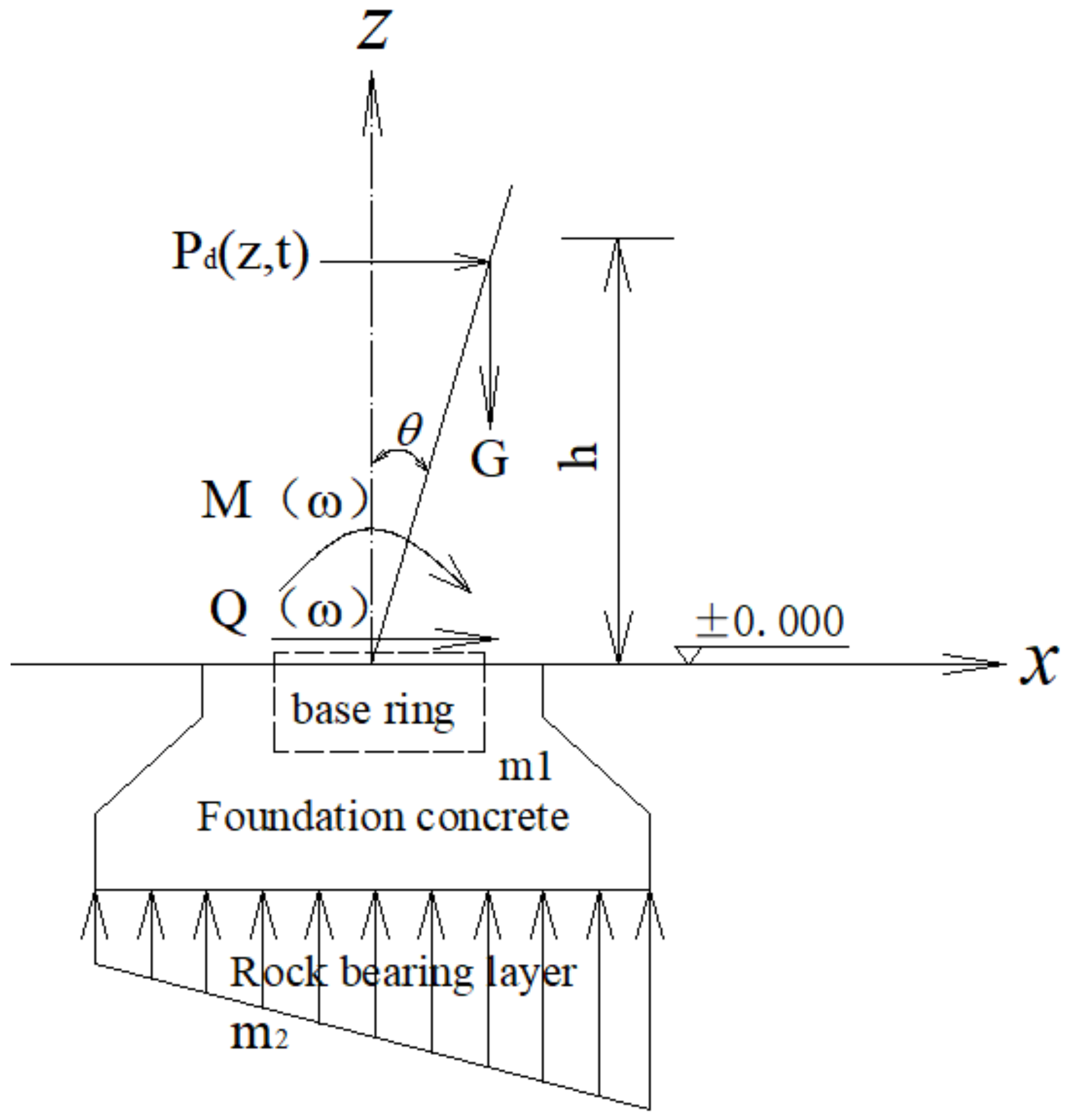
2. Mechanical Analysis of Rock Foundation under Wind Load

2.1. Wind Load

This paper takes the onshore wind power generation system as the object. According to the composition of wind turbine, the engine room and tower frame are the superstructure, and the foundation and rock bearing layer are the substructure. The superstructure mainly bears the wind load directly, and the substructure is also seriously affected by the natural environment and construction condition under the condition of the wind load transmitted, the additional stress of the base, and the upper self-weight. These influencing factors are the important root cause of wind-induced disaster unit collapse [12,13]. It is obvious that wind load is a critical load acting on land wind turbine. In addition, its standard value is mainly wind pressure and pulsating wind pressure. Meanwhile, the wind turbine is a towering structure, and the superstructure is mainly affected by downwind gradient wind and wind shear. Wind-induced response mainly causes the tower tube to be destroyed by excessive deformation in the form of bending, shear, and torsion. The lower foundation structure is mainly affected by wind load transfer and foundation bearing capacity. These mechanical properties have important influence on foundation stability. At the same time, the bending moment and shear force caused by the upper wind load also have an important influence on the bearing capacity and deformation of rock mass, thus promoting the shear and punching failure of the foundation. Therefore, the mechanical effect of wind load on the whole wind turbine and the deformation of foundation cannot be ignored.
According to literature [14], under normal wind conditions, the standard wind load value is mainly composed of averaging wind and pulsating wind to determine the standard wind load value. At present, the pulse wind speed spectrum mainly includes Davenport spectrum, Kaimal spectrum, and Simiu spectrum. Considering the energy of onshore fluctuating wind, it is mainly concentrated in the low-frequency band. Moreover, the wind vibration response of the instability failure of the towering structure is present in the middle and lower part of the structure. In addition, the height variation characteristics of the wind speed spectrum of onshore wind farm are not considered temporarily. Therefore, Kaimal fluctuating wind speed spectrum is adopted in the study of wind-induced disasters of tower drum, and the power spectrum of its downwind horizontal fluctuating wind speed is expressed as follows [14]:
(1) Follow the direction of the wind
n S u ( n ) v s 2 = 105 n z U z ( 1 + 33 n z U z ) 5 / 3
(2) Vertical direction
n S w ( n ) v s 2 = 2.1 n z U z ( 1 + 5.3 n z U z ) 5 / 3
where S u ( n ) , S w ( n ) are the self-spectral density functions of downwind and vertical pulsating wind speed processes, respectively; n is frequency; v s is shear wave velocity of wind load; z is height above the earth’s surface; and U z is average wave velocity at height of z .
Under normal wind conditions, according to Rayleigh distribution, the distribution of average wind speed at the height of wind turbine within 10 min is determined, which can be obtained from the following equation:
v R = 1 - exp [ - π ( v h / 2 v a ) 2 ]
The standard deviation of wind speed in normal turbulence model was determined by 90% quantile of wind velocity at given hub height. It can be written as
σ v = P f ( 0.75 v h + b )
where P f is the turbulent intensity at the hub height and b is calculated parameter.
Meanwhile, the fluctuating wind load acting on the tower tube structure can be calculated by the following equation:
P d = 1 2 A i μ s ρ a ( v 10 + v f ) 2
where v 10 is the average value of the basic wind speed, ρ a is air density, A i is windscreen area of tower, μ s is wind load shape coefficient, and v f is the fluctuating wind speed.

2.2. Wind Vibration Model

As a random vibration load, wind load has a continuous mechanical effect on the stability of high-rise structures. In particular, wind load has the duality of driving impeller and wind vibration response to wind turbine. Therefore, the negative effects caused by wind load should be strictly controlled. According to the inherent mechanical properties and strength differences of geotechnical materials of wind turbine substructure foundation, the foundation is regarded as forced viscous vibration of damping two grade of freedom system in wind vibration study. The specific vibration model is shown in Figure 1 [15].
In Figure 1, k 1 , k 2 , k 3 are the stiffness coefficients of tower tube foundation interface, soil, and stable soil layer, respectively; c 1 , c 2 , c 3 are the damping of the above structures, respectively.
According to the mechanical equilibrium of the system, the vibration equation can be derived from the following equation:
M 11 x 1 + C 11 x 1 + C 12 x 2 + K 11 x 1 + K 12 x 2 = F f 1 ( t ) M 22 x 2 + C 21 x 1 + C 22 x 2 + K 21 x 1 + K 22 x 2 = F f 2 ( t )
where M 11 = m 1 , M 22 = m 2 , C 11 = c 1 + c 2 , C 12 = C 21 = c 2 , C 22 = c 2 + c 3 , K 11 = k 1 + k 2 , K 12 = K 21 = k 2 , K 22 = k 2 + k 3 .
Combined with resonance characteristics, the solution of Equation (6) of inhomogeneous vibration has the following form as
x 1 = A 1 cos ( f t ) + B 1 sin ( f t ) x 2 = A 2 cos ( f t ) + B 2 sin ( f t )
The first and second derivatives of Equation (7) are derived into Equation (6) and can be obtained as follows:
x 1 = A 1 f 2 cos ( f t ) B 1 f 2 sin ( f t ) x 2 = A 2 f 2 cos ( f t ) B 2 f 2 sin ( f t )
Then, substituting Equations (7) and (8) into Equation (6), it can be proposed as follows:
C 21 f C 11 f K 11 K 21 M 11 f 2 C 12 f K 12 + M 22 f 2 C 22 K 22 K 11 - M 11 - K 12 C 11 f - C 21 f K 12 C 12 + M 22 f 2 C 22 K 22 sin ( f t ) cos ( f t ) = 0 0 0 0
Taking sin ( f t ) and cos ( f t ) as unknowns and considering that the coefficient of the determinant is zero, the frequency characteristic equation of wind turbine foundation and rock foundation can be obtained as follows:
a f 4 + b f 2 + c = 0
By solving the eigenvalues of Equation (10), f 1 2 and f 2 2 , the first-order natural frequency and the second-order natural frequency of foundation–rock foundation can be obtained.

2.3. Load Calculation of Rock Foundation

Wind turbine lower foundation usually adopts a foundation ring and anchor bolt structure due to its high bearing capacity, simple design, and complex geological and topographical conditions. In addition, the foundation ring has been widely used in onshore wind farms. According to the load condition and mode analysis of wind turbine, the pulsating wind speed spectrum, it is mainly considered that the tower cylinder is prone to produce the rotational deformation in the downwind direction and the horizontal wind load, thus forming the rotational bending moment and shear force. Considering foundation stiffness and displacement constraints, the vibration mode of the fan system is bending-shear type with up-bend and down-shear [16]. In addition, the dynamic interaction between tower tube and foundation will produce shear force Q ( t ) and bending moment M ( t ) on the interface between them. As the soil layer covered by fan foundation is thin, the influence of soil pressure inside the buried depth range of foundation is not considered [17]. Figure 2 shows the load distribution of the base–rock matrix structure.
Combined with the composition of average wind and fluctuating wind to determine the calculation method, the wind-induced shear force at the top of foundation ring is calculated as follows:
Q ( f ) = 0 H π D 2 A i μ s ρ a ( v 10 + v f ) 2 8 cos θ d z
The wind-induced moment at the top of the foundation ring is calculated as follows:
M ( f ) = 0 H π D 2 A i μ s ρ a ( v 10 + v f ) 2 8 cos θ z d z + 1 2 H G tan θ
where
θ = ( 1 + υ ) A i μ s ρ a ( v 10 + v f ) 2 E
where H is the height from the hub to the top surface of the foundation, D is the diameter of the tower cylinder, G is the dead weight of the superstructure, and E , υ is the elastic parameter of the superstructure.

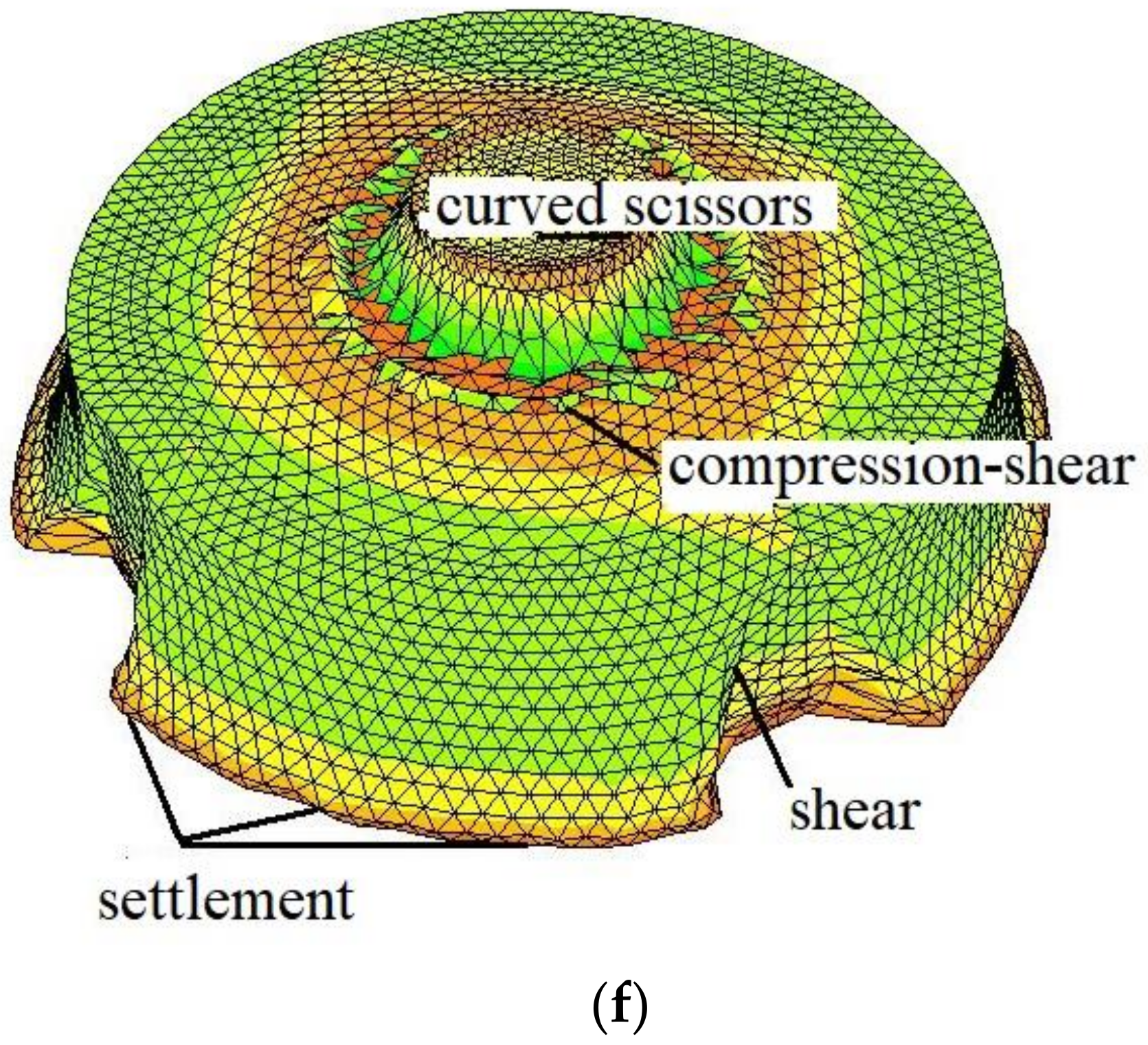
3. Fracture Characteristics of Fractured Rock Foundation

The surface load of wind turbine is transmitted to the rock foundation through the foundation ring; so, the bearing capacity of the rock determines the stable working condition of fan. Furthermore, the stress conditions, deformation characteristics, and crack propagation control of the foundation are very important. Usually, under the action of excessive load, the deformation characteristics such as punching, shear, and uneven settlement are produced, which easily induce the crack propagation and coalescing of fractured rock and accelerate the fracture failure of rock foundation. The crack propagation deformation is shown in Figure 3.
Considering load distribution of rock foundation matrix structure, the main load distribution of rock foundation cracks is compressive shear load; under the action of compressive shear load, rock foundation cracks produce composite shear deformation, namely, I-II type composite crack. Fracture failure of fissured rock base usually occurs when the stress at the crack front reaches the yield condition and produces a plastic zone, which further expands to produce fracture failure [18].
According to rock yield failure, the Mohr–Coulomb plastic yield condition was adopted under positive pressure and negative tension conditions:
f = 1 3 I 1 sin ϕ ( cos θ σ + 1 3 sin θ σ sin ϕ ) J 2 + c cos φ
where
θ σ = 1 3 sin 1 [ 3 3 2 J 3 ( J 2 ) 3 ]
where I 1 is the first invariant of stress tensor, and J 2 , J 3 are the second and three invariants of stress skew, respectively.
Combined with the stress distribution characteristics of the crack surface, the normal stress and shear stress in the crack direction are expressed as follows:
σ n = 1 2 2 π r [ K I cos θ 2 sin θ ( 1 + cos θ ) 3 K I I cos θ 2 sin 2 θ ]
τ n = 1 2 2 π r [ K I cos θ 2 ( cos θ + cos 2 θ ) 3 2 K I I cos θ 2 sin 2 θ ]
According to the Mohr–Coulomb theory, the principal stress distribution of I–II type composite crack under plane strain condition is proposed as follows [19]:
σ 1 = σ n + τ n cos φ ( 1 + sin φ ) = 1 2 2 π r [ K I ( A + 1 + sin φ cos φ C ) K I I ( B + 1 + sin φ cos φ D ) ]
σ 2 = 0
σ 3 = τ n tan φ + σ n = 1 2 2 π r [ K I ( C tan φ + A ) K I I ( D tan φ + B ) ]
where
A = cos θ 2 sin θ ( 1 + cos θ ) B = 3 cos θ 2 sin 2 θ C = cos θ 2 ( cos θ + cos 2 θ ) D = 3 2 cos θ 2 sin 2 θ
Furthermore, the Mohr–Coulomb plastic yield conditions were obtained:
f = 1 3 I 1 sin ϕ ( cos θ σ + 1 3 sin θ σ sin ϕ ) J 2 + c cos φ
For rock-base power hardening materials, we can obtain
σ = m ε n
According to the Mohr–Coulomb plastic yield relation and combined with the crack distribution, the upper limit of the ultimate load on the base is
P = b σ n B S ( W a )
where P is the upper limit of ultimate load of the base, a is the crack length, ( W a ) is the thickness of rock bridge, and B is the width of rock foundation.
Combined with the relation between C O D and J integral under elastic–plastic condition, the integral of crack ( J P ) under plastic yield is obtained as follows:
J P = d σ s C O D 2 r
where σ s is the yield stress, r is the plastic zone radius, and C O D is the crack tip opening displacement.
According to Dugdale model, crack tip opening displacement is written as follows:
C O D = 2.55 σ s E a ln sec ( π P 2 σ s )
Combining Equations (22) and (23), the integral of crack ( J P ) is obtained as follows:
J P = 1.275 a d σ s 2 E r ln sec ( π P 2 σ s )

4. Coupling Characteristics of Creep Fracture

4.1. Nonlinear Creep Analysis

It is clear that creep is one of the inherent mechanical properties of rock mass. It is the deformation that develops over time under external load. When creep load exceeds the rock mass long-term strength, accelerated deformation occurs. Furthermore, the engineering rock mass has been in a complicated subterranean environment for a long time; hence, the long-term strength can determine the rock mass aging deformation and engineering stability.
At the initial reinforcement stage, with time development and the bonding effect increases, rock mass presents instantaneous elastic–viscous displacement, which gradually recovers. When the load increases further, rock mass structural stress is adjusted and the creep expansion on cracks occurs, namely, the plastic shear yield condition is reached. Considering the rock mass deformation composition, shear failure criterion on fractured rock mass, and Mohr–Coulomb plastic yield condition, M–C element was conducted as a nonlinear creep element, which was connected in series with the classic Kelvin model to form a generalized nonlinear element model. Moreover, the modified creep model has a simple type and few components. The model parameters can be easily distinguished through creep experiments. Meanwhile, the improved model can also effectively characterize the rock mass three-stage creep characteristics. The Modified Kelvin Nonlinear creep model is shown in Figure 4.
Considering nonlinear element creep displacement characteristic, creep formulas of the Modified Kelvin Nonlinear creep model are obtained, and the nonlinear element is mainly reflected by viscosity coefficient.
As a classic Kelvin body, the creep equations can be written as follows:
S i j = 2 η e ˙ i j + 2 G e i j
ε = σ < η ( t , σ ) > τ τ f n
(1) When σ is less than σ g , the nonlinear coefficient of viscosity is expressed as follows:
< η ( t , σ ) > =
(2) When σ is greater than or equal to σ g , the nonlinear coefficient of viscosity is expressed as follows:
< η ( t , σ ) > = A t ( ln t 0 t + 1 ) + B [ arctan ( ln σ σ t ) + π 2 ]
The nonlinear M–C body is depicted as follows:
e ˙ i j P = λ g σ i j 1 3 e ˙ v o l P δ i j
e i j p = s i j ( 1 2 G p + 1 k d λ )
e ˙ v o l P = λ g σ 11 + g σ 22 + g σ 33 λ = G η s i j = k s i j 0
where k is the rheology experimental parameters, A , B is the rheology experimental constant, and S i j , e i j is the partial stress and strain of toughened resin rock mass structure, respectively, η is viscosity coefficient, G is shear modulus, g is the plastic potential function, δ i j is Kirschner symbol, σ 11 , σ 33 are the maximum and minimum principal stress, respectively, σ g is plastic yield limit of M–C element, σ t is tensile strength.
According to the Mohr–Coulomb plastic yield condition, the improved nonlinear creep model equation is obtained by applying the principle of strain addition:
e i j = S i j 2 G [ 1 exp ( G η ) t ] + s i j ( 1 2 G p + 1 k d λ )
Considering the plastic yield criterion of rock mass, the accelerated creep failure time t F of foundation rock mass can be further obtained as follows:
t F = t 0 + 1 0 h k ε 0 W exp ( π d z ) τ f
where t 0 is the yield initial time of bedrock body, τ f is the yield initial strength of rock mass, and ε 0 is the accelerated creep initial strain.
In the parameter distinguishment of the modified nonlinear creep model, according to creep curves and creep isochronic curves of different loads, the model calculated parameters and long-term strength are usually proposed. Under F ( ) certain creep load, the long-term bearing capacity is t = , where the rheology time is t = . In fact, when the long-term bearing capacity is reached, accelerated failure deformation occurs.

4.2. Coupling Characteristics of Creep Fracture
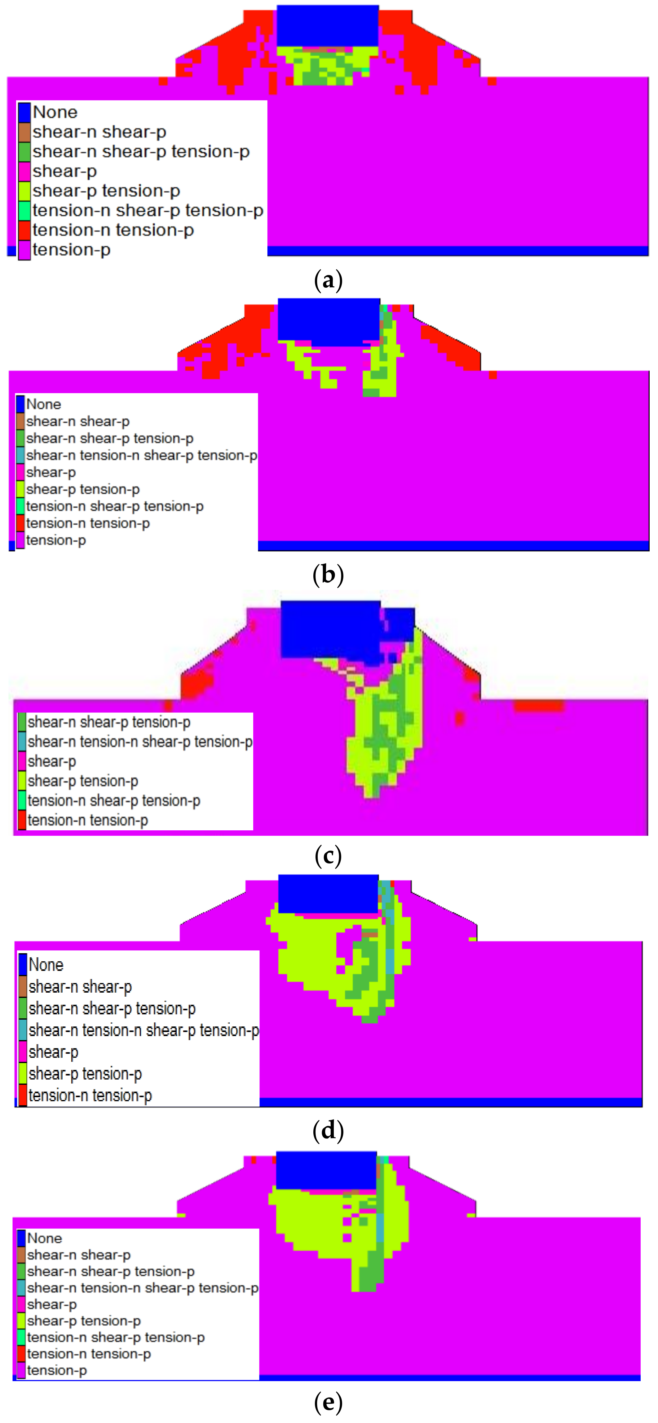
Under the action of superstructure and foundation load, rock foundation will produce creep deformation. With the increase in load, the rock foundation will be destroyed by accelerated creep deformation when the yield limit is reached. At the same time, the increase in load will induce the formation and propagation of main cracks. When the crack expands, the strength of bedrock decreases and the stress state changes constantly, which makes the creep stress reach the yield limit of bedrock body and accelerates the creep failure.
According to creep characteristics of the self-built nonlinear M–C body, when creep load reaches the yield limit of bedrock body, the M–C body will produce accelerated plastic deformation. Furthermore, the fracture creep equation of the creep effect of bedrock body can be obtained as follows:
e 1 = 2 σ 1 - σ 3 6 G [ 1 exp ( G η ( t , σ ) ) t ] + 2 σ 1 - σ 3 3 ( 1 2 G p + 1 k d λ )
e 3 = 2 σ 3 - σ 1 6 G [ 1 exp ( G η ( t , σ ) ) t ] + 2 σ 3 - σ 1 3 ( 1 2 G p + 1 k d λ )
Equations (16) and (18) are substituted into Equations (30) and (31), respectively, to obtain the crack tip principal stress.
Furthermore, accelerated creep failure ( t F ) time of foundation rock mass can be further obtained as follows:
t F = t 0 + 1 0 h k ε 0 W exp ( π d z ) 1 2 2 π r P [ K I cos θ 0 2 ( cos θ 0 + cos 2 θ 0 ) 3 2 K I I cos θ 0 2 sin 2 θ 0 ]
Considering the maximum normal stress, the direction angle of crack propagation θ 0 , the plastic zone of crack tip, and the time of accelerated creep failure can be obtained.

5. Example Analysis

In order to verify the stability effect of rock foundation creep fracture on wind turbine, considering the shear failure characteristics of rock, and taking shear inclined crack power hardening rock foundation as the research object, the influence of tower wind vibration effect of base pressure on the rock foundation creep fracture was analyzed. The wind turbine of Guanjiazui wind farm in Qidong County of Hunan province is taken as the research object (see Figure 5). Considering the wind-induced vibration response, the additional stress of foundation is four times the depth and two times the width of foundation. The calculation range is characterized by a width of 38 m and thickness of 10 m. The foundation structure adopts the foundation ring expanded with a slab concrete structure; the design strength is set to 310 MPa with concrete strength of C30. The foundation holding layer is the rock layer. The rock foundation is mainly sandstone, which is characterized by joints without developing. The damping ratio is 0.03, tower frame height is 70 m, and foundation buried depth is 2.5 m. The rock foundation calculated parameters are listed in Table 1.
The average value of the basic wind speed is 9.5 m/s, the density of the air is 1.26 Kg/m³, the wind load shape coefficient is 1.4, the coefficients related to ground roughness is 0.005, the fluctuating wind speed is from −2.1~3.5 m/s, the power spectral density is 0.002~0.5 m2/s, the wind load shape coefficient is 1.466, and the basic wind pressure is 0.5 kPa. In the simulation, the boundary conditions are fixed in the lower part, constrained in the periphery of the rock base, and free in the upper part. In order to eliminate the boundary effect, viscous damping is set in the lower part and on the left and right sides of the computational model, respectively.
Through the modified Kelvin nonlinear accelerated rheology model, the finite difference calculation program is developed for coupling characteristics of creep fracture under wind vibration. On the wind turbine foundation–batholith structure, the vertical displacement, plastic zone, acceleration of crack extension, wind-induced disaster creep failure time, and failure state were obtained in the four cases as follows: (a) without considering wind load, creep, and fracture; (b) considering wind load without creep and fracture; (c) considering wind load creep without fracture; (d) considering creep fracture under wind load. The calculation model is divided into a total of 16,884 nodes and 84,141 tetrahedron units. In the simulation, boundary conditions for the lower is fixed to constrain surrounding the foundation soil; however, the upper is freedom. In order to conduct the boundary influence, in the calculation model, the lower, left, and right sides are set up for viscous damping. Its calculation model, boundary conditions, and mesh division are shown in Figure 6 and Figure 7.
Figure 8 illustrates the vertical displacement distribution. On the wind turbine concrete foundation–subsoil foundation frame, vertical displacement is mainly negative displacement, which existed in bottom. Without considering wind load, creep, and fracture in view of foundation and rock foundation lay, the maximum vertical displacement is 9.7 mm, mainly distributing at the top of the base ring. However, the vertical displacement of concrete foundation and deep rock foundation lay is very small. Meanwhile, the wind turbine appears to be in a stable state. Considering wind load without creep and fracture, the instantaneous maximum vertical displacement of rock foundation is 1.5 cm, which is mainly distributed in the downwind foundation ring and the right side of concrete foundation. Considering wind load creep without fracture, the maximum vertical displacement of rock foundation is 2.8 cm, which develops horizontally and deeply from the foundation circumferential to rock base. After wind load is applied for 18 h, the vertical displacement of rock foundation also appears at 4 mm. Considering creep fracture under wind load, the vertical displacement of concrete foundation and rock foundation continues to increase. After wind load has continued for 26.2 h, the vertical displacement of rock foundation is more than 3.3 cm. Meanwhile, the maximal displacements are mainly distributed in the leeward-based ring to interface with rock base. Compared with the creep without fracture, the vertical displacement increased by 120%; hence, the displacement rate is significant. At the same time, there is also a vertical displacement of 1 cm at the position of foundation cone slope, and the foundation has obvious deformation, which has seriously affected the stability of concrete foundation and rock foundation. Furthermore, it is shown from the failure state of the wind-induced disaster concrete foundation and rock foundation. Meanwhile, the wind load is 27.1 h and the maximum vertical displacement is 13 cm, which causes accelerating deformation status, base bending shear, compressive shear destruction, differential settlement of rock at the grass-roots level, and shear destruction. Evidently, the former is mainly caused by wind load transferring the bending moment and shear stress at the tower drum bottom. The differential settlement of rock foundation is caused by eccentric additional stress of foundation and produces shear instability.
Figure 9 illustrates the distribution of plastic state under various cases. The plastic regions are mainly shear without considering wind load, creep, and fracture and the plastic zones are mainly distributed at the bottom of the base ring. Moreover, with the strength of the play, the plastic zone decreases and through plastic zone has not formed. Meanwhile, wind turbine has a stable state. Considering wind load without creep and fracture, the plastic zone is mainly distributed in the downwind foundation ring and the shallow area on the right side of concrete foundation, and the plastic zone increases and gradually breaks through. Considering wind load creep without fracture, the plastic zone of foundation ring and shallow layer on the right side of concrete foundation appears to increase in the downwind direction, and develops from the bottom of foundation ring to the bottom of rock base. After 18 h of wind load, the plastic zone of rock foundation increases in the deep. When the creep fracture under wind load is considered, the plastic region of the rock foundation continues to increase. After 26.2 h wind load, the plastic zone at the bottom of the foundation ring appears and continues to expand, which seriously affects the stability of the foundation and rock base. After 27.1 h of wind load, the plastic zone at the bottom of the foundation ring is connected, and a shear zone is formed in the crack area of the rock base. Meanwhile, the rock foundation showed obvious shear failure.

6. Conclusions

Theoretical research and engineering application of wind load response of wind turbine foundation rock structure are carried out in terms of load distribution, vibration characteristics, creep fracture effect of rock mass, additional stress of base, plastic zone, crack growth, and accelerated creep failure time. Meanwhile, the following conclusions are obtained.
(1) Based on the mechanical condition of wind turbine rock foundation, considering each component strength difference, the vibration model and equation of the two grade freedom system with viscous damping in foundation–rock structure are established. Moreover, the frequency characteristic equation of foundation–rock is obtained. Simultaneously, the analytical expressions of wind-induced shear stress and bending moment at the top of the foundation are also proposed.
(2) According to wind turbine composition, the wind turbine is divided into two parts including the upper part and the lower part by the interface between the tower frame and foundation. According to the material physical and mechanical properties, the system composition and boundary conditions meet the viscous damping force vibration model of two grade freedom system; further, the vibration equation of concrete foundation and rock foundation is obtained, and the first-order natural frequency and the second-order natural frequency of concrete foundation and rock foundation are obtained. According to the wind vibration response and the deformation characteristics of rock foundation, the nonlinear creep model, the nonlinear characteristics of viscosity coefficient, the time of accelerated creep failure, the analytic formula of maximum additional stress of basement, and the motion equation of rock mass are also established.
(3) Combined with the calculation examples, it is verified that the vertical displacement change rate and the plastic zone of the foundation structure are significant considering the creep fracture effect of the foundation under wind load. The resulting differential settlement and the penetration of the plastic zone pose a serious danger to the stability of wind turbine. Therefore, improving the strength of the interface between concrete foundation and rock foundation on shallow surface rock mass, reducing the propagation of cracks, and enhancing the shear capacity of the concrete in the main wind direction and the cone slope are important ways to reduce instability.

Author Contributions

Data curation, methodology, editing, J.W.; investigation, Z.N.; formal analysis, P.C.; writing—original draft preparation, all authors. All authors have read and agreed to the published version of the manuscript.

Funding

This work was supported by the Natural Science Foundation of Hunan Province (No.2019JJ40056) and Scientific Research Foundation of Hunan Province Education Department (No.18A345).

Institutional Review Board Statement

Not applicable.

Informed Consent Statement

Not applicable.

Data Availability Statement

Not applicable.

Conflicts of Interest

The authors declare no conflict of interest.

References

  1. Chen, R.; Xue, S.T.; Wang, Y.G.; Qin, L. Effects of soil-structure interaction on the responses of structure to wind-induced vibration. Chin. J. Rock Mech. Eng. 2003, 22, 309–315. [Google Scholar] [CrossRef]
  2. Veletsos, A.S.; Verbic, B. Vibration of Viscoelastic foundation. Earthq. Eng. Struct. Dyn. 1973, 2, 87–102. [Google Scholar] [CrossRef]
  3. Zhang, B.; Ren, H.H.; Chen, W.L.; Li, Q. Wind field simulation of Jjianshan area under complex terrain. J. Nat. Diasters 2017, 26, 22–31. [Google Scholar] [CrossRef]
  4. Lian, S.; Li, J.; Gan, F.; Bi, J.; Wang, C.; Zheng, K. Investigation of the shear mechanicalbehavior of sandstone with unloading normal stress after freezing-thawing cycles. Machines 2021, 9, 339. [Google Scholar] [CrossRef]
  5. Yang, W.G.; Wang, Z.Q.; Zhu, B.W.; Qi, L.Z. Time history analysis on wind-induced response of UHV guyed single-mast transmission-line system. Proc. CSCE 2015, 3, 3182–3191. [Google Scholar] [CrossRef]
  6. Fang, C.X.; Chen, R.; Xue, S.T. Effect of pile-soil-structure interaction on downwind response of highrise building to wind-induced vibration. Chin. J. Rock Mech. Eng. 2004, 23, 2078–2084. [Google Scholar]
  7. Feng, Y.J.; Su, H.J.; Nie, Y.J.; Zhao, H.H. Role of cyclic thermal shocks on the physical and mechanical responses of white marble. Machines 2022, 10, 58. [Google Scholar] [CrossRef]
  8. Zhao, Y.L.; Wang, Y.X.; Wang, W.J.; Tang, L.M.; Liu, Q.; Cheng, G. Modeling of rheological fracture behavior of rock cracks subjected to hydraulic pressure and far field stresses. Theor. Appl. Fract. Mech. 2019, 101, 59–66. [Google Scholar] [CrossRef]
  9. Hao, Y.L.; Wang, Y.X.; Wang, W.J. Modeling of non-linear rheological behavior of hard rock using triaxial rheological experiment. Int. J. Rock Mech. Min. Sci. 2017, 93, 66–75. [Google Scholar] [CrossRef]
  10. Yuan, H.P.; Zhao, P.; Wang, Y.X.; Zhou, H.L.; Luo, Y.H.; Guo, P.P. Mechanism of deformation compatibility and pile foundation optimum for long-span tower foundation in flood-plain deposit zone. Int. J. Civ. Eng. 2017, 15, 887–894. [Google Scholar] [CrossRef]
  11. Liu, J.; Cao, P.; Han, D.Y. Sequential Indentation Tests to Investigate the Influence of Confining Stress on Rock Breakage by Tunnel Boring Machine Cutter in a Biaxial State. Rock Mech. Rock Eng. 2016, 49, 1479–1495. [Google Scholar] [CrossRef]
  12. Guo, Y.; Sun, B.N.; Ye, Y.; Lou, W.J.; Shen, G.H. Frequency-domain analysis on wind-induced dynamic response and vibration control of long span transmission line system. Acta Aerodyn. Sin. 2009, 27, 288–295. [Google Scholar]
  13. Li, Y.G.; Li, Q.S. Influence of fundamental mode shapes onequivalent static wind loads of tall buildings. Earthq. Eng. Eng. Dyn. 2016, 36, 38–44. [Google Scholar] [CrossRef]
  14. Zhang, W.F.; Ma, C.H. Notes on power spectrum density and wind-velocity PSD. Chin. J. Comput. Mech. 2008, 25, 474–477. [Google Scholar]
  15. Yang, X.L.; Liu, Z.A. Reliability analysis of three-dimensional rock slope. Geomech. Eng. 2018, 15, 1183–1191. [Google Scholar] [CrossRef]
  16. Zhang, C.Y.; Pu, C.Z.; Cao, R.H. The stability and roof-support optimization of roadways passing through unfavorable geological bodies using advanced detection and monitoring methods among others in the Sanmenxia Bauxite Mine in China’s Henan Province. Bull. Eng. Geol. Environ. 2019, 78, 5087–5099. [Google Scholar] [CrossRef]
  17. Hutchins, N.; Chauhan, K.; Marusic, I.; Monty, J.; Klewicki, J. Towards reconciling the large-scale structure of turbulent boundary layers in the atmospherd and laboratory. Bound.-Layer Meteorol. 2012, 145, 273–306. [Google Scholar] [CrossRef]
  18. Wang, Y.X.; Guo, P.P.; Ren, W.X.; Yuan, B.X. Laboratory investigation on strength characteristics of expansive soil treated with jute fiber reinforcement. Int. J. Geomechancis 2017, 17, 04017101. [Google Scholar] [CrossRef]
  19. Zhao, Y.L.; Zhang, L.Y.; Wang, W.J.; Wan, W.; Ma, W. Separation of elastoviscoplastic strains of rock and a nonlinear creep model. Int. J. Geomech. 2018, 18, 04017129. [Google Scholar] [CrossRef]
Figure 1. Forced vibration of foundation–soil.
Energies 15 03862 g001
Figure 2. Distribution of load on foundation–rock foundation structure.
Energies 15 03862 g002
Figure 3. Crack expands and deforms under load.
Energies 15 03862 g003
Figure 4. Modified Kelvin Nonlinear creep model.
Energies 15 03862 g004
Figure 5. The geographical location of wind farm.
Energies 15 03862 g005
Figure 6. Sketch of calculation and boundary (Unit: m).
Energies 15 03862 g006
Figure 7. Calculated meshing.
Energies 15 03862 g007
Figure 8. Vertical displacement distribution under various working conditions: (a) Without considering wind load, creep, and fracture; (b) considering wind load without creep and fracture; (c) considering wind load creep without fracture ( t = 18 h); (d) considering creep fracture under wind load ( t 0 = 26.2 h); (e) considering creep fracture under wind load ( t F = 27.1 h).
Energies 15 03862 g008aEnergies 15 03862 g008b
Figure 9. Distribution of plastic zone under various working conditions: (a) Without considering wind load, creep, and fracture; (b) considering wind load without creep and fracture; (c) considering wind load creep without fracture ( t = 18 h); (d) considering creep fracture under wind load ( t 0 = 26.2 h); (e) considering creep fracture under wind load ( t F = 27.1 h); (f) the creep fracture failure modes under wind load are considered ( t F = 27.1 h).
Energies 15 03862 g009aEnergies 15 03862 g009b
Table 1. The rock foundation calculated parameters.
LithologyWeight
/kN/m3
Poisson’s
Ratio
Rock Mass Strength
Internal Friction Angle Cohesion
/°/kPa
Elastic Modulus
/GPa
Viscoelastic Modulus
/GPa
Viscoelastic Coefficient
/MPaˑd
sandstone26.50.2544            1100222.57.6 × 103
Publisher’s Note: MDPI stays neutral with regard to jurisdictional claims in published maps and institutional affiliations.

