1. Introduction
The passive and efficient heat transfer in heat pipes is based on a continuous two-phase cycle of a working fluid contained in the hermetically sealed, typically tubular vessel of the heat pipe. The heat pipe can be divided into three sections: evaporator, adiabatic section and condenser. Heat input at one end of the heat pipe (evaporator) leads to evaporation of the working fluid while absorbing the latent heat of vaporization. Due to the resulting vapor pressure difference, the gas phase flows towards the other end of the heat pipe (condenser), where the heat is removed from the heat pipe by releasing the enthalpy of condensation. Due to this latent heat transport, the effective thermal conductivity of heat pipes can reach an order of magnitude of up to 10
5 W/(m K) [
1,
2]. In conventional heat pipes, the condensed liquid is returned to the evaporator by capillary forces, typically provided by mesh, sintered or grooved wick structures on the inner wall of the vessel. The special form of a heat pipe without a wick structure is called thermosiphon. This offers production and cost advantages due to the simpler structure. However, the thermosiphon relies solely on the effect of gravity for the return of the condensed liquid, i.e., it is only functional if the condenser is located above the evaporator. In a thermosiphon, the working fluid volume is decisive for the thermal performance. Due to the lack of capillary structure, special boiling conditions can occur in the evaporator (e.g., pool boiling) and entrainment between gas and liquid phase can be significant [
3]. A widely used working fluid of heat pipes and thermosiphons is water, but many other fluids are also used depending on the application and temperature range.
While heat pipes originally became known in the field of spacecraft thermal control, the main application of heat pipes today is in the cooling of electronic components in the mass market of consumer electronics. A novel field of research is to integrate heat pipes into machine tools to address thermal error compensation. According to [
4], up to three out of four geometric errors of machined workpieces are thermally induced. Heat pipes can be used for thermal connections between different machine parts, heat storage components and cooling elements to smoothen the temperature response of critical machine parts to varying heat input [
5,
6]. Another potential field of application is the battery thermal management system of lithium-ion batteries in electric vehicles. Heat pipes can be an effective and inexpensive means of maintaining the critical temperature boundary conditions of the battery cells to ensure safety and efficiency [
7,
8,
9].
A key problem of thermal control in the aforementioned applications is the temporal variation of the occurring heat loads and temperature boundary conditions. Thermal switches are an interesting approach to address this problem, in that they allow switching between a thermally conductive on state and an ideally insulating off state and thereby actively control the heat transport. A broad overview of existing concepts of thermal switches is given in [
10,
11]. These include conduction-based (thermal contact switches, changing thermal conductivity), convection-based (gas gap switches, heat pipes), and radiation-based mechanisms (view factor switching). The central characteristic of a thermal switch is the switching ratio
which can be expressed both as the ratio of the largest and smallest differential conductivity
and as the corresponding reciprocal of the thermal resistances
. Achievable switching ratios range from about 1 to over 500 [
10].
Heat pipes are a promising basis for thermal switches due to their passive and effective heat transfer, low mass, simple structure and low cost. Various heat pipe-based switch approaches have been introduced in the literature that differ significantly with regards to the switch characteristics, dimensions, and limits. Heat pipe-based switch concepts can be categorized into designs that are based on either external or internal working principle. Externally working heat pipe-based switches use varying contact conditions to alter the heat transfer. One approach which has been suggested is to combine heat pipes and shape memory alloys to realize a passive thermomechanical self-regulating switch. Concepts based on the use of shape memory alloy springs [
12] and wires [
13] were proposed and experimentally investigated. While the off state of such switches usually exhibits high thermal resistance due to the separation of the contact faces, the contact conditions in on state are often suboptimal.
A widely studied concept in the field of heat pipes with internal switch is the Variable Conductance Heat Pipe (VCHP). VCHP use a non-condensable gas (NCG) that is included into the pipe in addition to the working fluid. Depending on the operating temperature of the heat pipe, the NCG occupies a variable volume, blocking part of the condenser surface at low temperature or releasing it at higher temperature. Thereby, the effective thermal conductivity of the VCHP varies with temperature in the sense of a thermal regulator. More precise control of a VCHP in terms of a thermal switch is achieved by using complex NCG reservoirs and active pressure and volume control [
10,
14]. For example, the combination of a VCHP with a piston was examined in [
15]. However, VCHPs perform worse than a standard HP due to the effect of the NCGs. This is particularly evident as soon as the HPs exhibit an adverse-gravity orientation, even for small inclination angles [
16].
Recently, Winkler et al. presented a novel approach for thermal switching using a water-loaded adsorbent integrated in a heat pipe [
17]. The adsorbent releases significant amounts of water by desorption as soon as a certain temperature threshold is exceeded, and the released water can subsequently serve as the working fluid in the heat pipe for latent heat transport. This in turn enables a significant reduction in the thermal resistance of the heat pipe as soon as a certain temperature threshold or switching temperature is exceeded. Results from that work revealed a good agreement between the predictions concerning water release and the thermal behavior of the heat pipe. Depending on whether evaporator/condenser or the adiabatic section are considered, average switching ratios of approximately 3 and 18 were found, respectively.
The use of a magnetic valve within a heat pipe is proposed in [
18]. The underlying concept enables an electromagnet placed outside the heat pipe to induce the switching inside the pipe. A similar approach using a steel ball within a glass heat pipe is described in [
19]. The proposed concept aims at altering the inactive length of the evaporation section. This switch design offers the benefit of continuous regulation of the thermal resistance of the heat pipe by the externally induced movement of the ball. Glass was chosen as wall material to enable observation of the fluid behaviour inside the tube. It could be demonstrated that moving the ball by an external magnet towards the adiabatic section leads to an increased thermal resistance. A switching ratio between 5 and 13 depending on the heat input was obtained. Systems as described in [
18,
19] provide simple assemblies that can be adapted to various application fields as only a magnet or an electromagnet is needed outside the pipe.
This paper presents a novel thermosiphon based thermal switch concept. The proposed approach combines the use of externally generated magnet fields and an internally placed blockade mechanism. By means of this mechanism the nature of the fluid circulation within the thermosiphon can be switched between two states. The fabrication of a thermosiphon with such thermal switch as well as the experimental set-up for thermal characterization are described. To obtain a deeper understanding of the effect of the inserted switch mechanism, an additional thermosiphon without switch was fabricated and experimentally characterized. The experimental investigation focusses on the performance difference between the reference thermosiphon and the switchable thermosiphon in on state as well as the performance difference between the off and on state of the switchable thermosiphon. This results in thermal resistance curves for the different operating states.
2. Materials and Methods
In the following, the concept and the fabrication of the thermosiphon with thermal switch are described. The experimental set-up is illustrated and explanation on the test procedure is given.
2.1. Preliminary Considerations
The thermal performance of heat pipes is characterized by means of the thermal resistance and the heat transfer limit. The thermal resistance of a heat pipe is calculated by
with the evaporator temperature
, the condenser temperature
and the heat flux
. The thermal resistances of the different heat pipe sections contribute to the overall thermal resistance. For a conventional, tubular heat pipe, the axial and radial heat transport through wick and wall as well as the contact resistances between evaporator and condenser sections and the adjacent components can be represented by a thermal resistance network based on the corresponding section resistances as demonstrated in [
20]. In addition, the heat transfer via the vapor phase is characterized by a convective resistance.
The goal of the underlying investigations is to develop a switch mechanism that exhibits a high switching ratio as well as a high level of adaptability and transferability. While the conductive heat flow within the solid components does not provide convenient options for altering the thermal resistance of the heat pipe, the contact resistances and convective resistances allow for mechanisms that significantly affect the overall thermal resistance as pointed out above. In theory, a complete shut-off of the fluid circulation leads to a high switching ratio as the axial heat conduction through the wall and the wick exhibits a significantly higher thermal resistance than the convective heat transport. Hence, the present work focusses on a thermal switch approach that aims for active manipulation of the vapor flow within heat pipes. In order to examine the fundamental influence of the manipulation mechanism on the thermal performance without capillary structure, a thermosiphon was chosen as the basic design. A magnetic actuation design was chosen because it allows for a temperature-independent activation. Studies as in [
19] demonstrate that it is possible to alter the thermal resistance by means of axially moving components inside heat pipes. Therefore, a magnetically actuated, thermosiphon-based switch mechanism was realized and examined. An expected benefit of this combination is a low switching time compared to other mechanisms such as paraffin-based switches. In addition, the proposed switch design is applicable to a wide range of heat pipe types as it is not restricted to certain geometries or material combinations.
2.2. Actuator Design
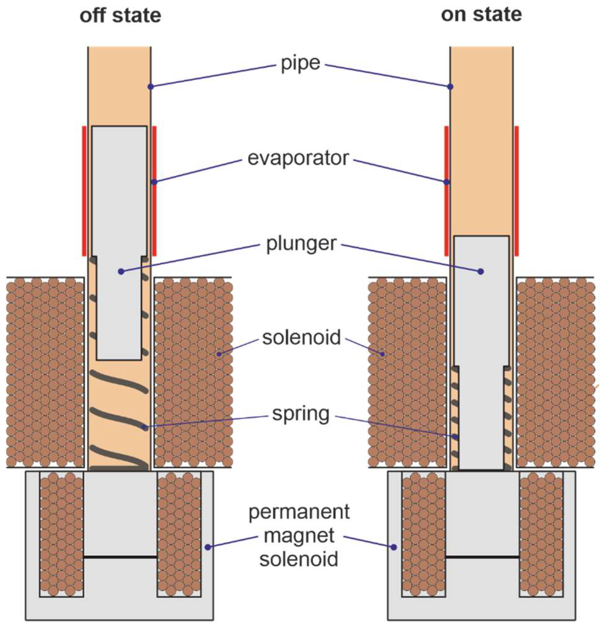
The developed switching concept aims at active manipulation of the thermal resistance during phase change in the evaporator section of the thermosiphon. For this purpose, the free surface for evaporation is changed by the position of a metallic plunger integrated into the evaporator section (see
Figure 1). By physically separating the working fluid from the nominal evaporator section, the thermal resistance between heat source and working fluid is sought to be increased. This approach is comparable to VCHPs where, instead of the evaporator, the condenser section is blocked. In the upper switching position (off state), the plunger blocks as much of the evaporator surface as possible. This increases the temperatures at the evaporator area, the vapor pressure increases and additionally prevents the condensed liquid from being returned. The thermal resistance of the evaporation is higher in this switching position, correspondingly also the total resistance of the heat pipe. In the lower switching position (on state), the plunger is below the evaporator area so that evaporation takes place without restrictions and thermal resistance is lower. It is expected that the switching ratio mainly depends on the evaporator surface covered by the plunger in off state.
The plunger, made of stainless steel alloy 1.4104 (X14CrMoS17), is bonded with a mechanical compression spring (VD-090Y by Gutekunst + Co. KG, Metzingen, Germany) and is inserted into the heat pipe, but not axially fixed. In the radial direction, there is a slight clearance between the plunger and the heat pipe inner wall, so the movement of the plunger is not restricted. The positioning motion of the plunger of approximately 20 mm between upper and lower switching positions is realized by a developed electromagnetic linear actuator. The actuator consists of a solenoid, a commercially available permanent electromagnet (4230023 by Mannel Magnettechnik GmbH & Co. KG, Remscheid, Germany) and the compression spring. This linear actuator is bistable, i.e., it has two currentless end positions. This is significant because continuous operation of an electromagnet would introduce too much additional heat into the heat pipe. The switching principle works as follows: The plunger is held in the upper end position (off state) by the mechanical compression spring. To switch to the lower end position (on state), an impulse of 1.5 A is applied to the solenoid (consisting of approximately 1600 turns of 0.5 mm enameled copper wire). The resulting solenoid magnetic field generates a downward force on the ferromagnetic plunger. In the lower end position, the plunger is in contact with the thermosiphon cover plate, through which the permanent magnet below exerts the currentless holding force. For the return to the upper end position, an electrical impulse is applied to the permanent magnet solenoid. This causes both magnetic fields to cancel each other out exactly, the holding force disappears and the plunger is moved upwards by the spring.
2.3. Thermosiphon Assembly
A 12 mm copper tube was used to fabricate the thermosiphon. One end was sealed by soldering of a copper cover plate to the tube. A copper adapter with internal thread was soldered to the other end of the pipe after inserting the spring and the plunger. A shut-off valve was connected to the adapter on the upper end of the pipe. The vacuum was applied by a vacuum pump connected to the open valve. The vacuum pump used for evacuation exhibits an ultimate pressure of 2 mbar. Afterwards, 2.2 mL of water were sucked into the pipe and the valve was closed.
In addition to the switchable thermosiphon a thermosiphon without thermal switch was fabricated. The geometrical parameters of the reference heat pipe coincide with the dimensions of the switchable thermosiphon except for the length. To provide the same distance between evaporator and condenser section for reference and switchable thermosiphon (in on state), the reference thermosiphon is 50 mm shorter than the switchable thermosiphon. The specifications of the thermosiphons are listed in
Table 1.
Enameled copper wire was wrapped around the evaporator section serving as a heat source. The heating wires were positioned above the cover plate on the reference and above the solenoid on the switchable thermosiphon. A silicone strip was wrapped around the heating wires to reduce convective heat dissipation at the evaporator section to the ambient air.
At the condenser section, two copper blocks with dimensions of 25 mm × 40 mm × 70 mm were mounted on each thermosiphon. Each copper block exhibits two drill holes with a diameter of 9 mm serving as channels for the cooling fluid.
Two thermocouples type-K were placed on each thermosiphon section (evaporator, adiabatic and condenser section). An additional thermocouple was used to measure the ambient temperature. The thermosiphon assemblies as well as the position of the temperature sensors are illustrated in
Figure 2.
2.4. Experimental Set-Up and Procedure
Both thermosiphons were tested in vertical alignment. A DC power supply (R&S
®HMP4030 by Rohde & Schwarz GmbH & Co. KG, Munich, Germany) provided the electric current for the heating wires as well as for the solenoids during switching. Silicone oil was used to cool down the copper blocks at the condenser section. A circulation thermostat (ECO Silver RE 420 by LAUDA DR. R. WOBSER GMBH & CO. KG, Lauda-Königshofen, Germany) provided the cooling and circulation of the silicone oil. The power input and the temperature sensor data were logged using a data acquisition module (OMB-DAQ-2416 by OMEGA Engineering, Deckenpfronn, Germany). The control of power input into the heating wires was controlled within a LABVIEW environment. A schematic representation of the entire experimental set-up is shown in
Figure 3.
To provide similar initial conditions for each heating phase, a 30 min cooling period was realized before applying the heat load to the thermosiphon. The oil temperature was set to 20 °C which is in the order of typical environmental temperature values at the location of the experimental set-up. For each heating phase, the heating wires were supplied with current for at least 60 min. In case that stationary state has not been reached after 60 min, the heating phase was extended by additional 30 min. Afterwards, the evaluation of stationary state criterion was repeated. The temperature field was defined to be stationary when the temporal fluctuation of the temperature values were found to be below 0.5 K within a period of 30 min. The first and second heating levels were defined as 5 W and 12 W, respectively, followed by 20 W and subsequently added 10 W for each stationary state reached within the allowed temperature range. The upper temperature limit was constrained to 100 °C to avoid decomposition of the heating wire insulation. The thermal resistance was calculated by means of Equation (2) using the mean values of the measured temperatures on the evaporator (CH1 and CH2) and the condenser section (CH5 and CH6).
Three test series were conducted. Firstly, the reference thermosiphon without switch was characterized (reference test). Afterwards, the thermosiphon with integrated switch was experimentally investigated in off state (off-state test). The final test series of the switchable thermosiphon were conducted in on state (on-state test). Each test series was repeated twice, in order to obtain information on the reproducibility of the results. The relative standard deviation (RSD)
was calculated for each set of repeated experiments, where
denotes the index of the measurement and
the mean thermal resistance within the set.
3. Results and Discussion
The experimental results are evaluated by means of the thermal resistances. The resistance curves of the reference thermosiphon and the thermosiphon with thermal switch in on and off state are illustrated and compared. In addition, the deviation between the results obtained at nominally similar load scenarios are evaluated. The results for all three test cases are listed in
Table 2.
3.1. Reference Thermosiphon
The reference thermosiphon was examined at heating levels between 5 W and 90 W. Thermal loading at 100 W did not lead to stationary temperatures within the allowed temperature range. The thermal resistance was obtained for each test leading to three resistance values for each heating level. The mean values of the thermal resistance for the reference thermosiphon are illustrated in
Figure 4.
The thermal resistance curve as a function of the heat input demonstrates a typical monotonically decreasing trend. The mean thermal resistance obtained by the measurements varies between 5.07 K/W at 5 W and 0.58 K/W at 90 W. The maximum relative standard deviation for the reference test was found to be 3.2% (see
Table 2).
3.2. Thermosiphon with Thermal Switch
In order to evaluate the thermal switch performance, the results of the off-state test and on-state test are compared. The mean thermal resistance as a function of the heat input for the switchable thermosiphon is illustrated in
Figure 4.
During the off-state test, the thermal resistance was determined for heating levels between 5 W and 40 W. Heating levels above 40 W led to surpassing the critical set-up temperature. Stationary temperature fields could therefore not be obtained for heating levels of 50 W and above. The maximum heating level applied to the thermosiphon in on state was significantly higher due to the improved heat transfer behavior after switching on. Similarly to the reference test, heating levels of up to 90 W could be realized without exceeding the critical temperature at the evaporator section. The results demonstrate that the reference thermosiphon and the thermosiphon with switch in on state exhibit similar behavior for most heating levels. It can hence be stated that the switch mechanism in on state does not lead to a significant disturbance of the thermosiphon operation. The on-state mean thermal resistance was observed to be significantly below the off-state and reference values. The maximum difference occurred at the heating level of 40 W with the off-state thermal resistance being around 53% higher than the on-state thermal resistance.
Figure 5 demonstrates the thermosiphon behavior upon switching for an exemplary heating level. The initially switched-off thermosiphon was switched on after 5400 s and switched off after 12,600 s while being constantly loaded with 35 W. The mean evaporator temperature in off state amounts to 86 °C in steady state and is found to be reduced by approximately 20 K within seconds after switching on. At the adiabatic section and the condenser section the switching to on state leads to a slight temperature rise. The total temperature gradient between evaporator and condenser section consequently decreases. After switching off, the temperature values return to the initial levels.
In off state, a high temperature difference of up to 21 K between the sensors placed on the nominal evaporator section can be observed. This indicates an upward shifting of the effective evaporator section. CH1 is placed at the lower part of the (nominal) evaporator section. In off state that area is blocked by the plunger leading to reduced phase transition processes of the displaced water. CH2 is located close to the upper end of the plunger in off state. The significantly lower temperature of CH2 is a consequence of the phase change that takes place close to the sensor. As the phase transition enthalpy is absorbed at a higher position in off state, the temperature of CH2 is affected more strongly by the phase change. The resulting temperature gradient between CH1 and CH2 demonstrates both the efficacy and the deficit of the proposed concept: The evaporation of the water is partially hindered by the plunger in off state, but not completely shut off as the water still receives a significant share of the heat input. While the measured temperature gradient proves the increased thermal resistance between the heat source and the evaporating water, the fluid circulation in off state maintains due to conductive heat transfer of the incoming heat through the plunger and the thermosiphon wall towards the water. For further enhancement of the switching effect, a greater resistance between heat source and water must be provided in off state.
Within the range of 5 W and 40 W, the switching ratio was calculated according to Equation (1). The result is illustrated in
Figure 6. It can be seen that the switching effect is small for low heating levels but increases the higher the heat load. The maximum switching ratio obtained from the experiments amounts to approximately 1.53 for a heating level of 40 W. The correlation between switching ratio and heat input appears to be almost linear and implies further increase in the switching ratio for heating levels above 40 W.
The maximum relative standard deviations for off-state test and on-state test were found to be 3.3% and 0.9%, respectively. These values represent a convenient level of repeatability of the conducted experiments. Possible reasons for the occurring deviations are unsteady ambient temperatures and flow conditions leading to varying convective heat transport on the surfaces of the set-up. The measurement uncertainty is mainly defined by the accuracy of the used thermocouples. The maximum measurement error of the thermocouples amounts to 1.5 °C. With respect to the determined thermal resistance values between evaporator and condenser section, this leads to a maximum absolute error of 3 K per heat input.


