
Innovative Single-Day Installation Vessel for Offshore Wind Turbines


Abstract
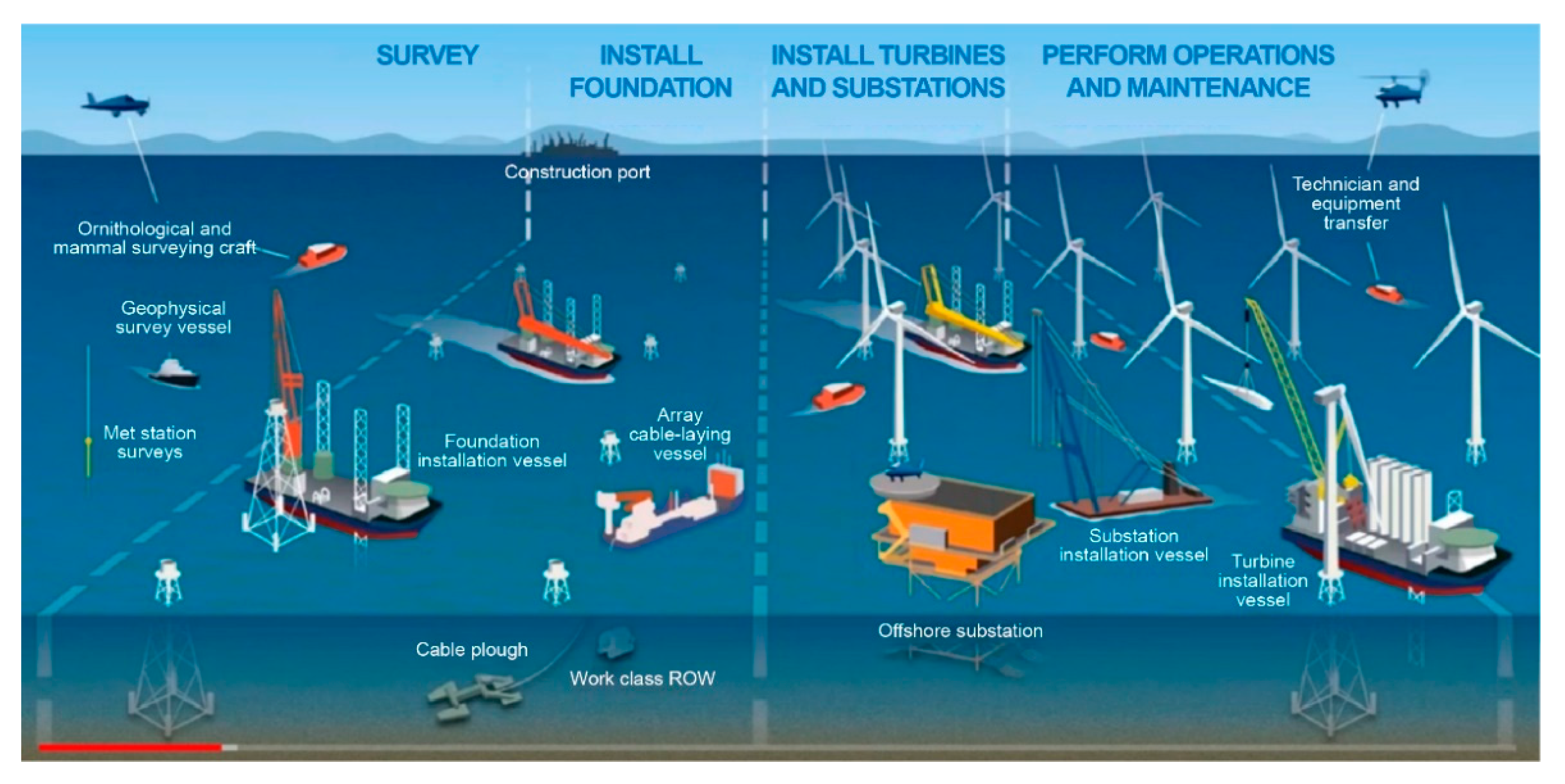
:1. Introduction
2. Basic Design and Safety Analysis
2.1. Basic Concept of Multipurpose Mobile Base
2.2. System Definition and Basic Assumptions
- The wind turbine is a rigid rod that is reduced to a point mass at the CG.
- The wind turbine is connected to the two points of the fixed MMB frame at the same height as the wires.
- The initial angle between the wire and the wind turbine structure is constant.
- The attachment between the wire and the wind turbine are assumed to be an ideal hinge (moment-free).
- During operation, the wire length does not increase as a function of the load.
- The hydraulic fixing device on the upper part of the A-frame acts as a rotational and horizontal stiffness for the wind turbine.
- The wire system for fixing the lower part acts as a horizontal stiffness.
- The wind turbine is initially in equilibrium (vertical upright).
- The change in the angle of the wire is very small.
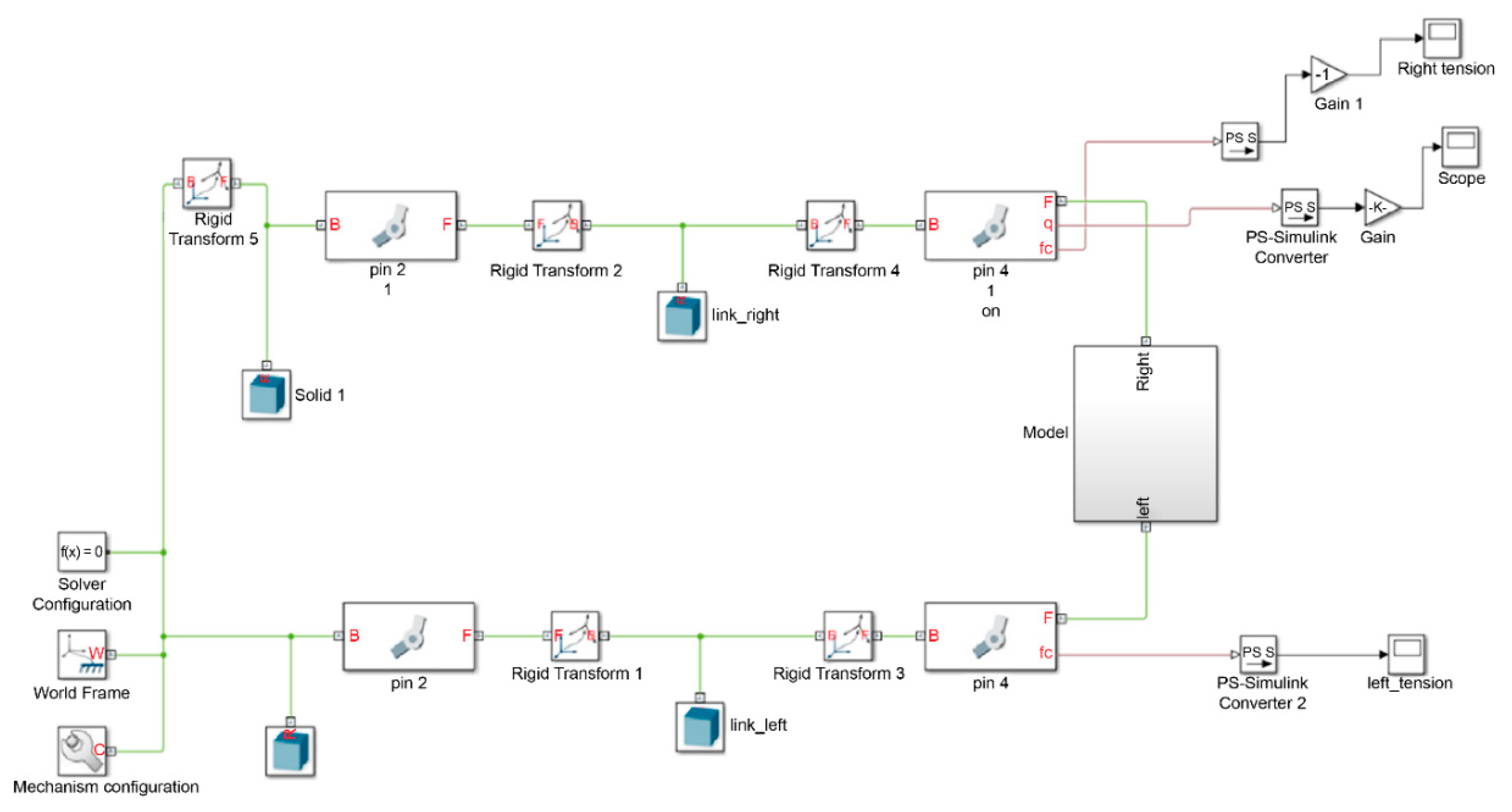
2.3. System Analysis
2.4. Validation of Analytic Approach Based a Small Model Test
3. Structural Design and Fabrication of the MMB
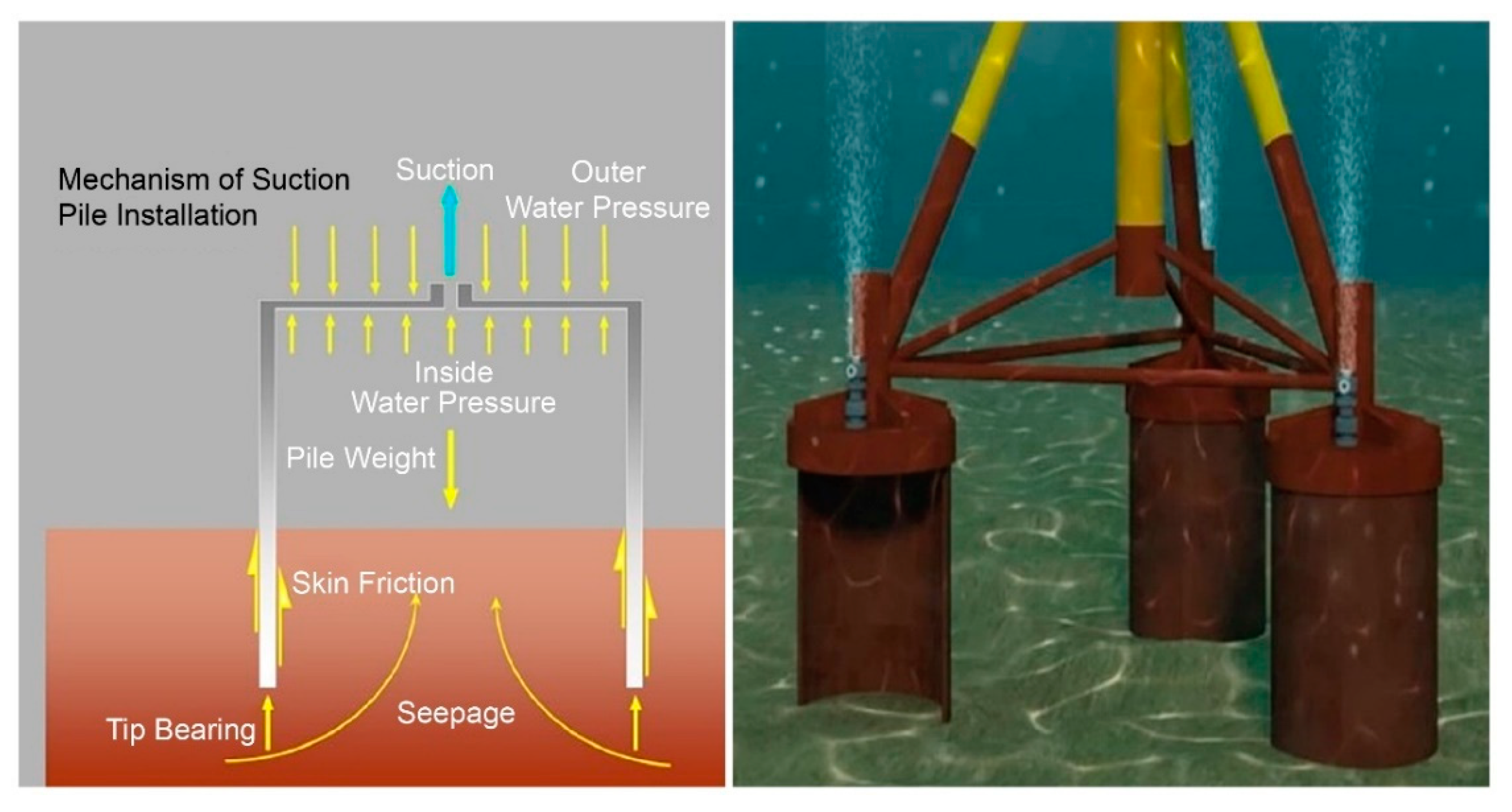
3.1. Suction Bucket Uplift Analysis
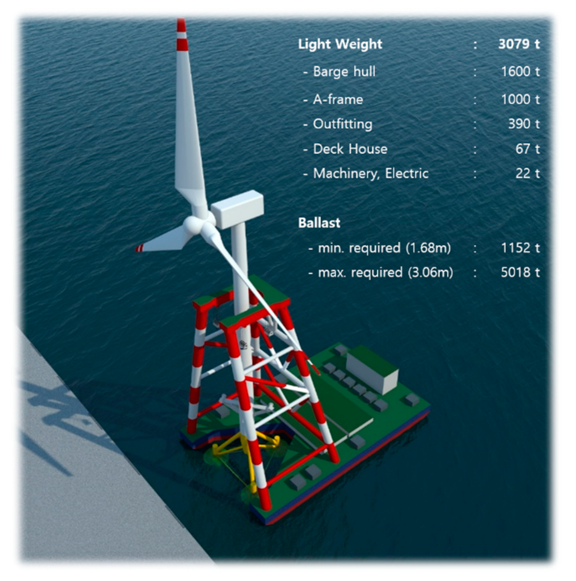
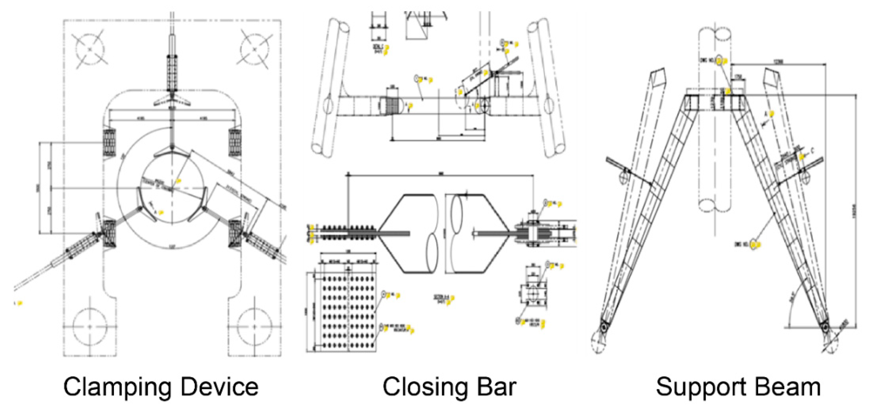
3.2. Fabrication of the MMB
4. Field Test and Performance Evaluation
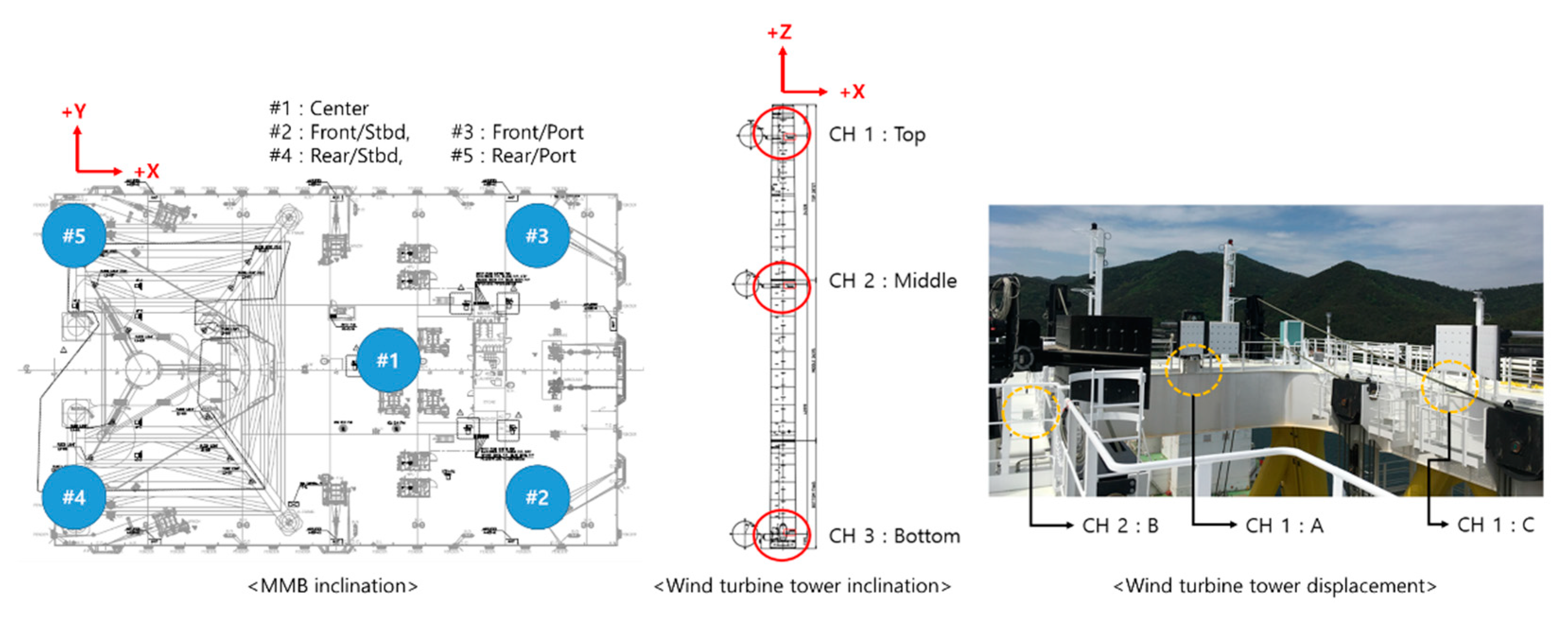
4.1. Measurement Configuration
4.2. Measurement Conditions
4.3. Field Test and Results
5. Conclusions
- A two-dimensional analysis model was developed for the assembly in which the wind turbine and the support structure were combined, and the condition of the vertical distance between the wire connection point and the CG of the wind turbine required to prevent overturning during hoisting/unloading of the wind turbine was presented according to Equation (2). Based on the analysis, it is possible to control sudden changes in the MMB behavior because the location of the wire connection point can be calculated in consideration of the operating range (moving distance between the top and bottom) when the wind turbine is hoisted using the MMB.
- To verify the two-dimensional wind turbine behavior analysis method, a scaled-down model was prepared and tested, and the analysis method was verified based on its comparison with the theoretically predicted result. Moreover, additional verification was performed with the use of the SPLC, and the accuracy of the technique was verified based on the intercomparison of the results. The natural frequency calculation result of the two-dimensional analysis model, the theoretical analysis result of 0.72 Hz, the numerical analysis model at 0.71 Hz, and the scaled model field test at 0.72 Hz, confirmed that the theoretical formula, the test result, and the rigid body analysis result obtained by the commercial program agreed closely.
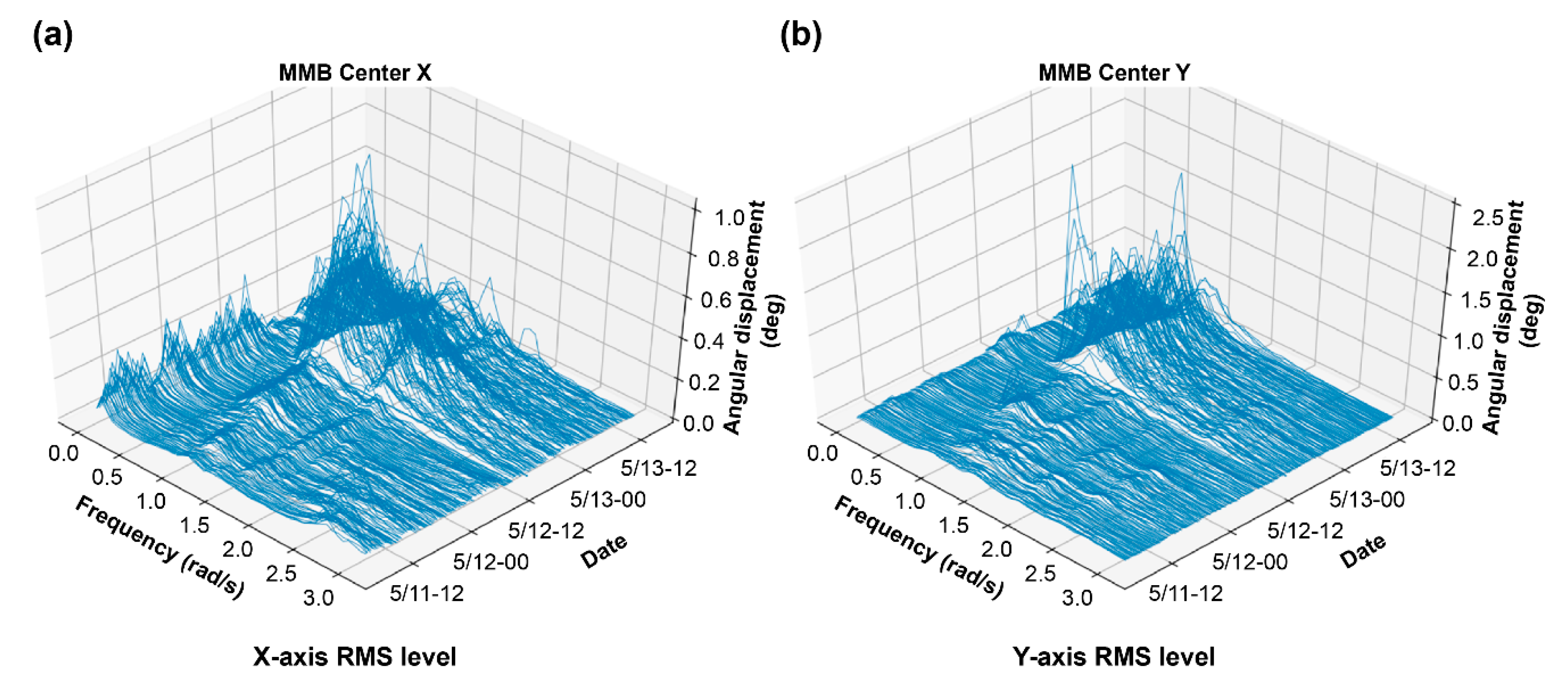
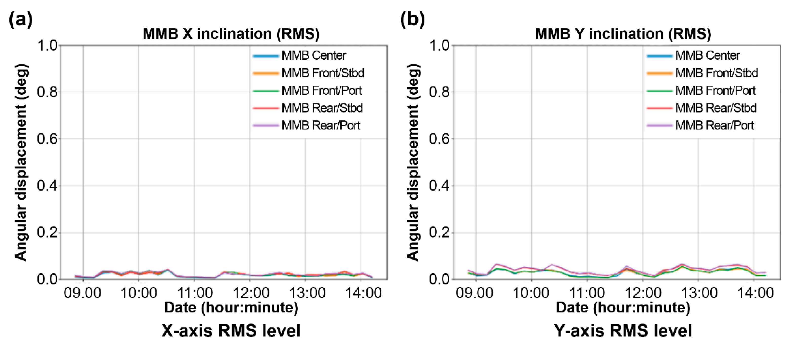
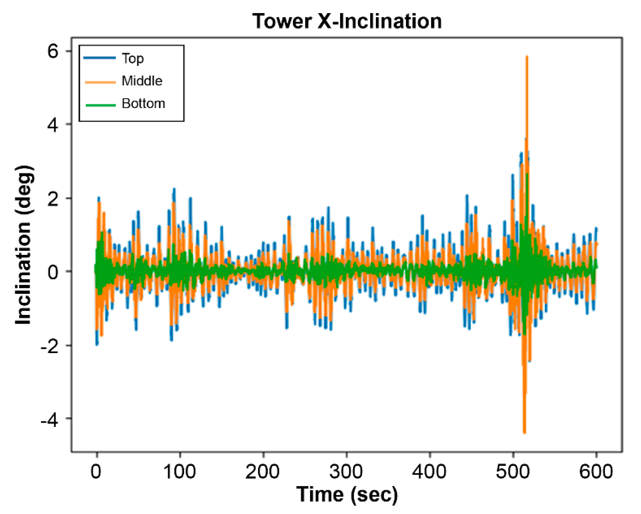
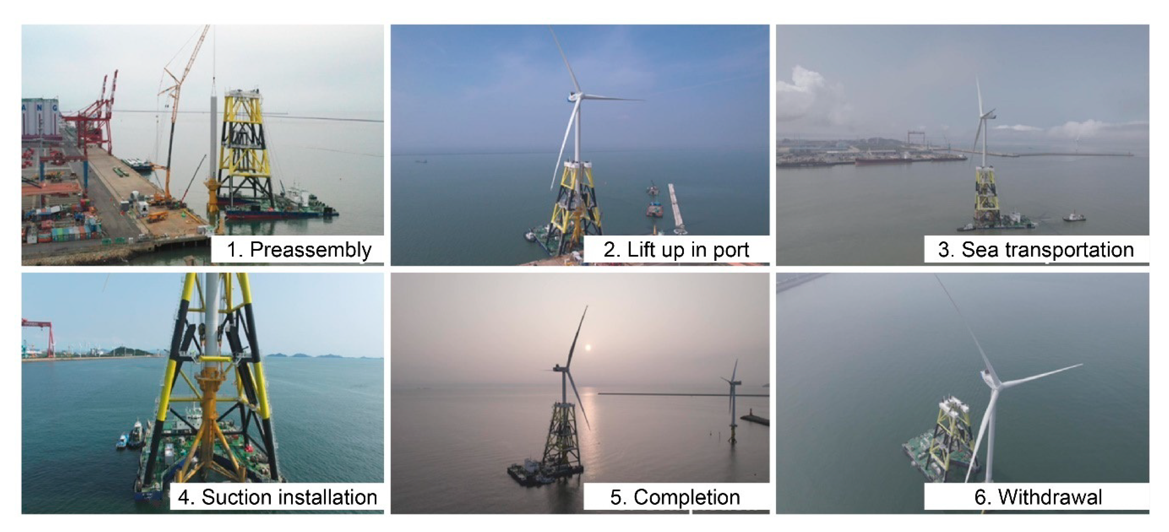
- Field demonstration was conducted for an actual 4.2 MW commercial turbine, and the dynamic behaviors of the MMB and wind tower were recorded by the measurement system. The following conclusions were obtained. It was confirmed that the main frequency component of the dynamic behavior of the MMB in the no-load state (without the wind turbine assembly) was almost consistent with the periodic data of ocean waves. In addition, the behavior of the MMB when the wind turbine assembly was mounted was not very different to the no-load state for both the hull and the tower. In the actual A.I.O.I demonstration test, very stable values were obtained. The respective changes in inclination at the center of the MMB and the tower were within 0.1° and 0.2° during operation because of the reduction of longitudinal and transverse sway of the MMB induced by the self-weight assembly and ballast.
6. Patents
Author Contributions
Funding
Institutional Review Board Statement
Informed Consent Statement
Data Availability Statement
Acknowledgments
Conflicts of Interest
References and Notes
- Global Wind Energy Council. Global Wind Report 2022; Global Wind Energy Council: Brussels, Belgium, 2022. [Google Scholar]
- European Environment Agency. Europe’s Onshore and Offshore Wind Energy Potential: An Assessment of Environmental and Economic Constraints; EEA Technical Report No. 6; European Environment Agency: Copenhagen, Denmark, 2009. [Google Scholar]
- Ryu, M.; Lee, J.; Kwag, D.; Seo, Y. Verification of tripod suction pile applicability through dynamic characteristic analysis of offshore wind turbine at each installation stage. J. Korea Wind Energy Assoc. 2019, 10, 12–21. [Google Scholar]
- Ryu, M.; Jung, M.; Lee, J.; Kim, D. Closed form solutions for predicting lateral response of tripod suction pile for offshore wind turbine foundation. Energies 2020, 13, 6176. [Google Scholar] [CrossRef]
- Seo, Y.; Ryu, M.; Oh, K. Dynamic characteristics of an offshore wind turbine with tripod suction buckets via full-scale testing. Complexity 2020, 2020, 3079308. [Google Scholar] [CrossRef]
- Webinar: An offshore wind vessel and other O&G sector opportunities, Clean Energy Group, 6 June 2017.
- Korea wind energy industry association, 2020.
- Norton, R.R. Design of Machinery; McGraw-Hill: New York, NY, USA, 1999. [Google Scholar]
- Bang, S.; Cho, Y. Suction pile loading capacity evaluation program, 2006.
- Ministry of Oceans and Fisheries. Standard of the Structure and Equipments for Barge Ships (Article 28); Notification of Ministry of Oceans and Fisheries 2020–109; Ministry of Oceans and Fisheries: Sejong City, Korea, 2020. (In Korean)


| (m) | 1 | 1 | 1 | |
| (m) | 0.122 | 0.122 | 0.122 | |
| (m) | 0.292 | 0.292 | 0.292 | |
| (m) | 0.07 | 0.07 | 0.07 | |
| (°) | 6.67 | 6.67 | 6.67 | |
| (kg) | 5.83 | 5.83 | 5.83 | |
| Dummy weight (kg) | 0 | 1 | 2 | |
| Natural frequency (Hz) | Theoretical model | 0.71 | 0.60 | 0.53 |
| Numerical model | 0.71 | 0.61 | 0.54 | |
| Experiment | 0.72 | 0.62 | 0.56 | |
| Category | Sea State | Water Depth | Current Speed | Wind Speed | Wind Turbine | Working Sea Area |
|---|---|---|---|---|---|---|
| details | 3 | <20 m | <1.2 m/s | <8 m/s | 4.2 MW, D136 m | inshore zone |
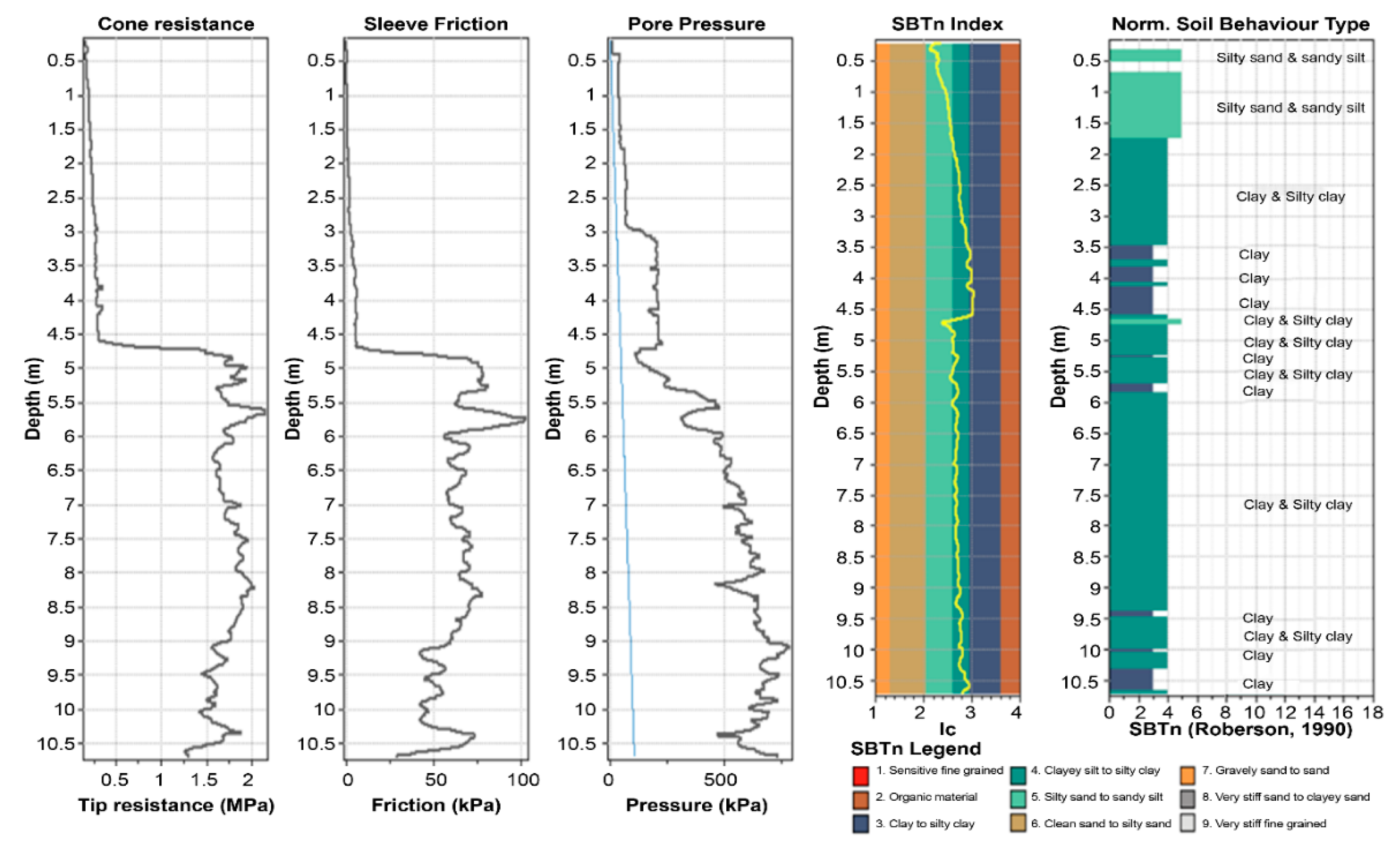
| Depth (m) | Soil | N Value | Unit Density (kg/m3) | Undrained Shear Strength (kPa) |
|---|---|---|---|---|
| 0.2–4.5 | clay | 1/30 | 17.5 | 15.5 |
| 4.5–10.7 | 7/30 | 17.5 | 105.9 |
| Category | Design Value | |
|---|---|---|
| Pile parameters | length | 9.3 m |
| diameter | 8.0 m | |
| wall thickness | 20 mm | |
| cap thickness | 25 mm | |
| Hydraulic condition | water depth | 10 m |
| unit weight of water | 10.1 kN/m3 | |
| Loading condition | suction bucket under water weight | 2461 kN/each |
| Category | Date in 2021 | Operation Condition | Operation Time | Seastate |
|---|---|---|---|---|
| case 1 | 12–13 May | sailing without (w/o) wind turbine | 20 h | 2~3 |
| case 2 | 2 July | sailing with (w/) wind turbine | 4 h | 2 |
| case 3 | 4 July | mooring w/wind turbine | 13 h | 3 |
| case 4 | 9 July | sailing w/wind turbine | 4 h | 2 |
| case 5 | 9 July | lowering of wind turbine | 6 h | 2 |
Publisher’s Note: MDPI stays neutral with regard to jurisdictional claims in published maps and institutional affiliations. |
© 2022 by the authors. Licensee MDPI, Basel, Switzerland. This article is an open access article distributed under the terms and conditions of the Creative Commons Attribution (CC BY) license (https://creativecommons.org/licenses/by/4.0/).
Share and Cite
Ryu, M.-S.; Kim, S.-R.; Cho, D.-H.; Kang, J.-G. Innovative Single-Day Installation Vessel for Offshore Wind Turbines. Energies 2022, 15, 3914. https://doi.org/10.3390/en15113914
Ryu M-S, Kim S-R, Cho D-H, Kang J-G. Innovative Single-Day Installation Vessel for Offshore Wind Turbines. Energies. 2022; 15(11):3914. https://doi.org/10.3390/en15113914
Chicago/Turabian StyleRyu, Moo-Sung, Sang-Ryul Kim, Dong-Ho Cho, and Joon-Goo Kang. 2022. "Innovative Single-Day Installation Vessel for Offshore Wind Turbines" Energies 15, no. 11: 3914. https://doi.org/10.3390/en15113914