
Development of a High Perfomance Gas Thermoelectric Generator (TEG) with Possibible Use of Waste Heat

 ,
, 

Abstract
:
1. Introduction
2. Technology
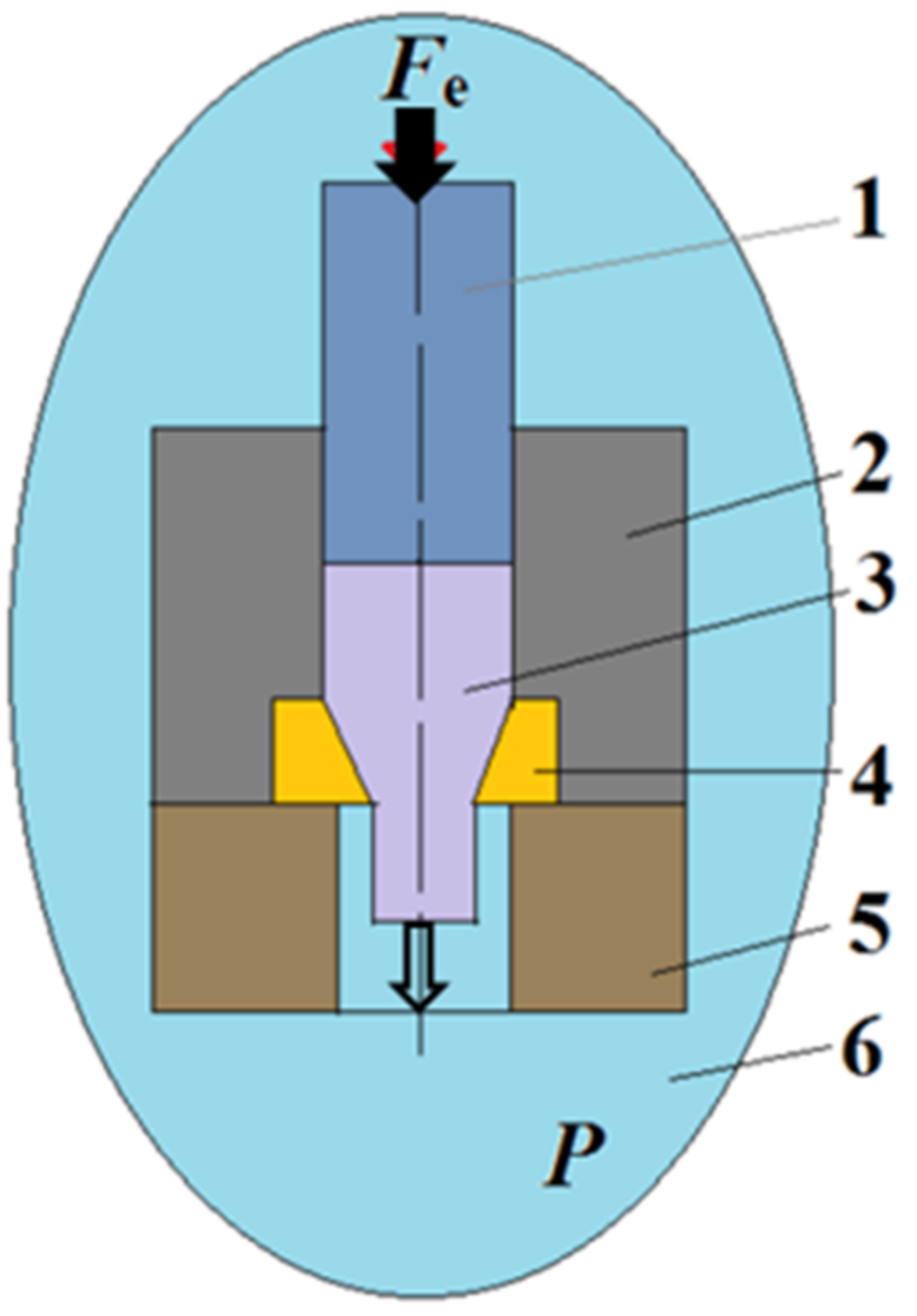
2.1. Hot Extrusion
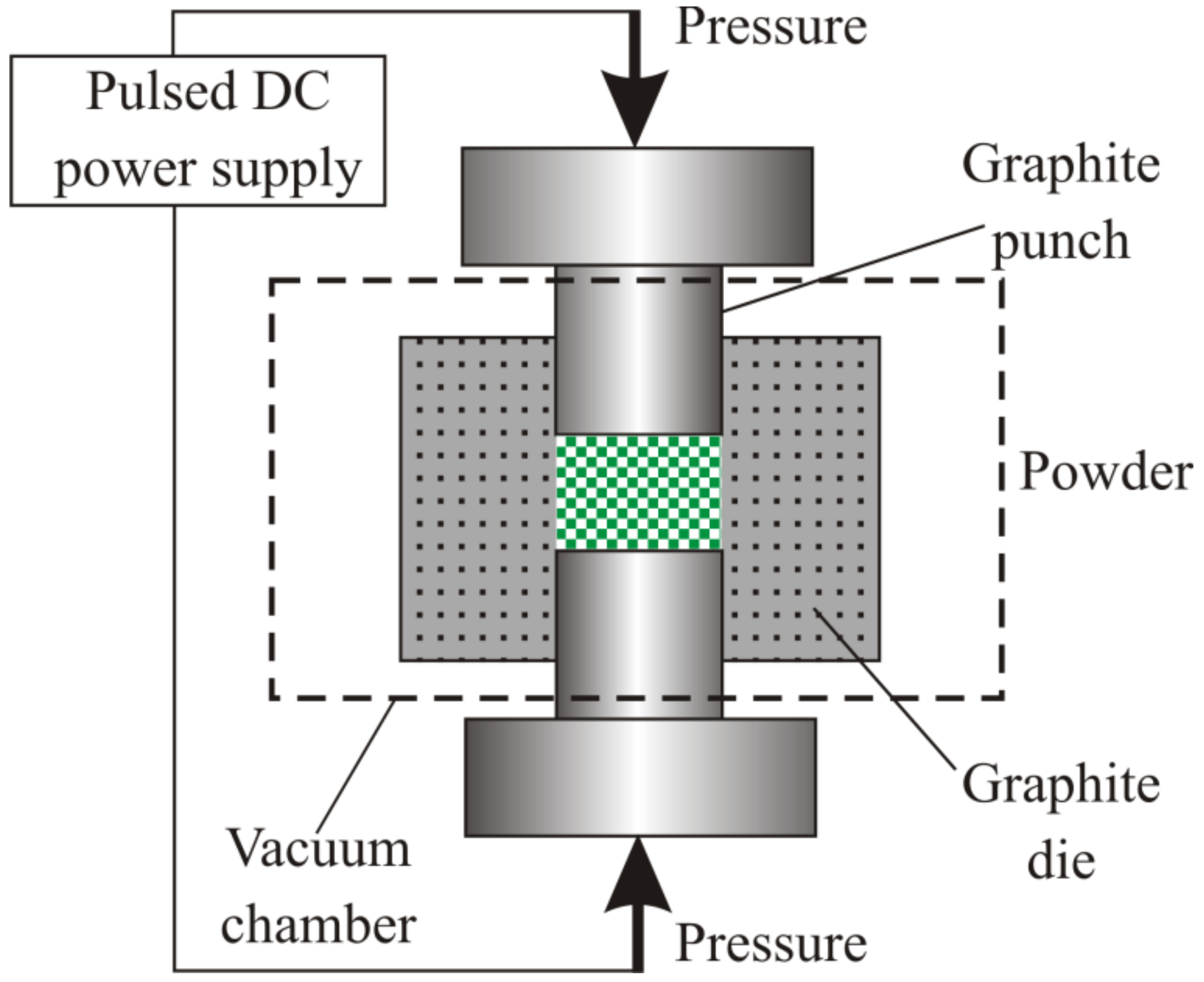
2.2. SPS Method
3. Characterization
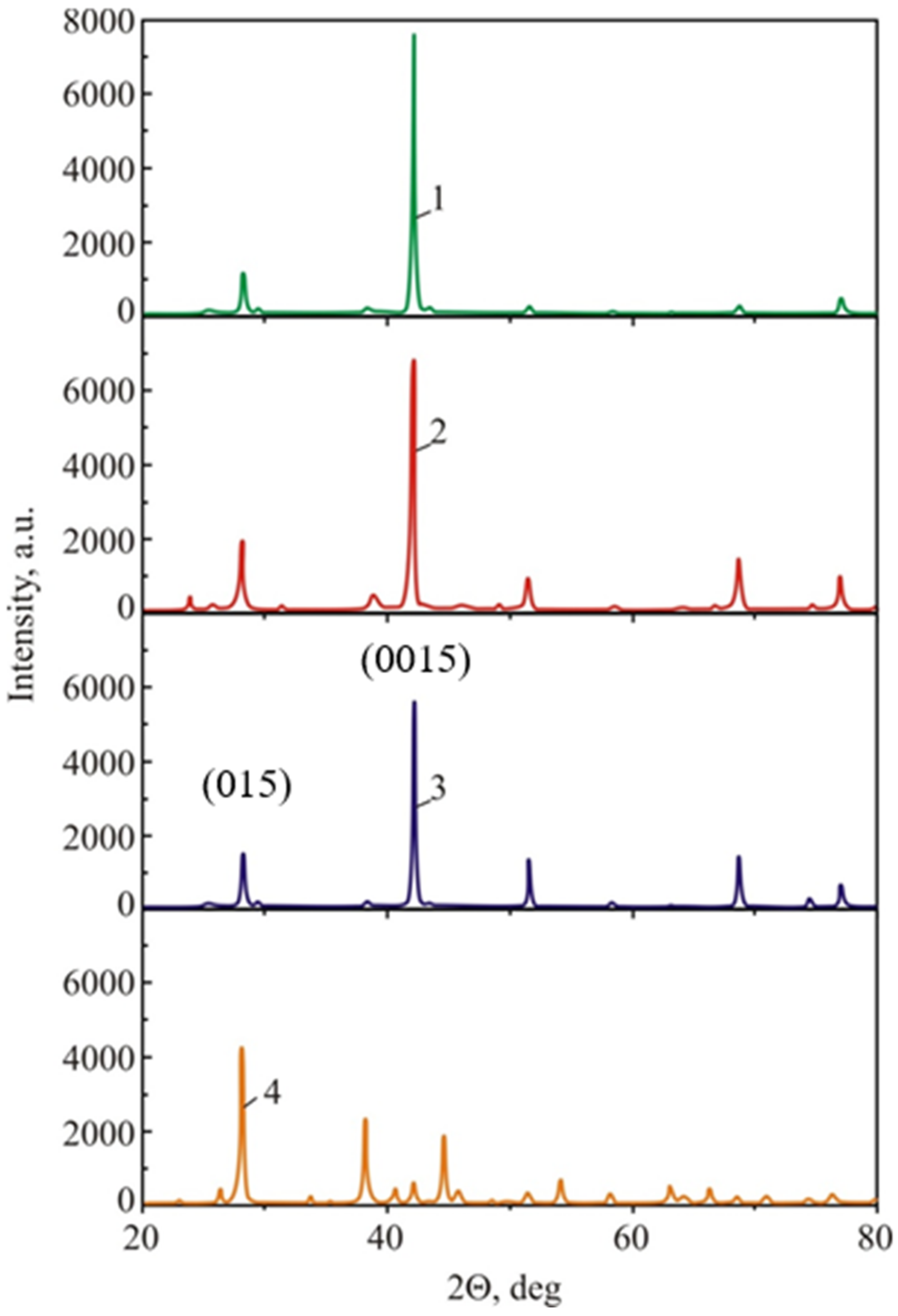
3.1. Structural Characterization
3.2. Mechanical Testing
3.3. Thermoelectric Properties Measurement
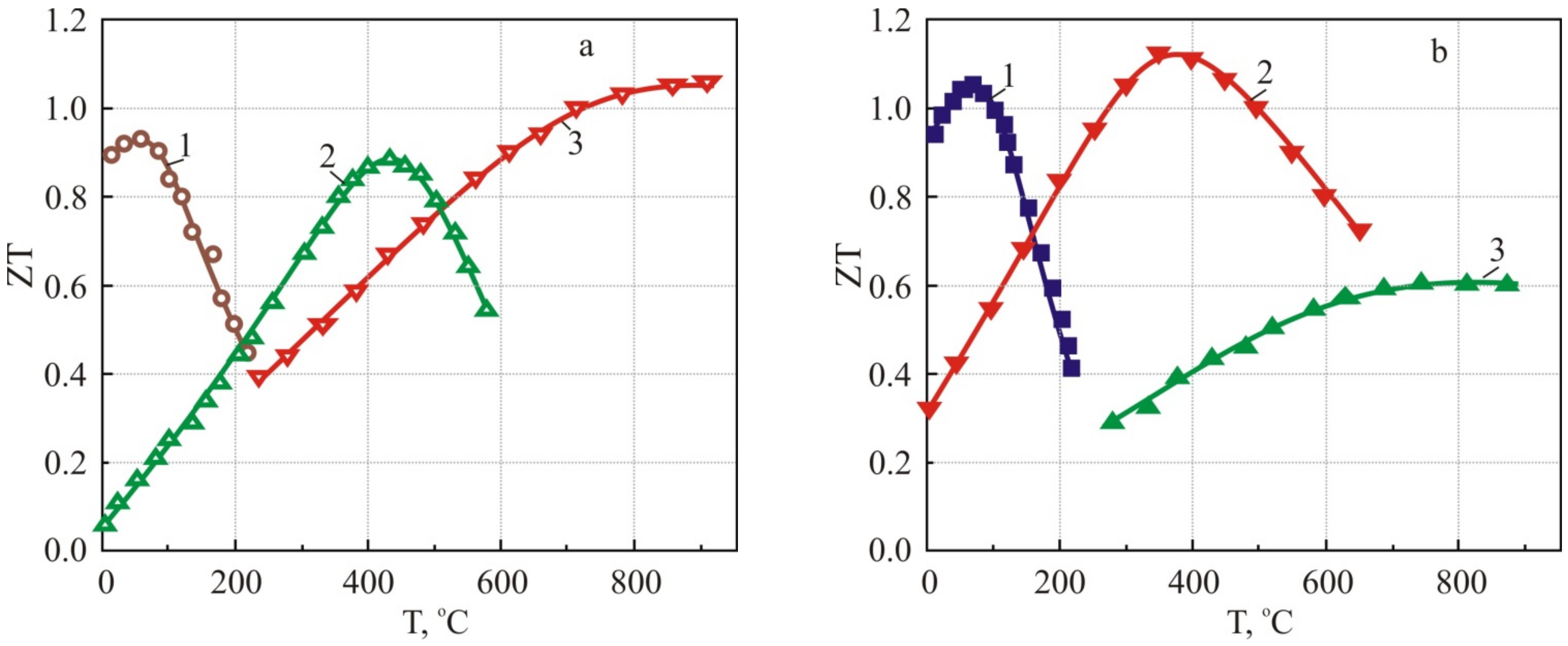
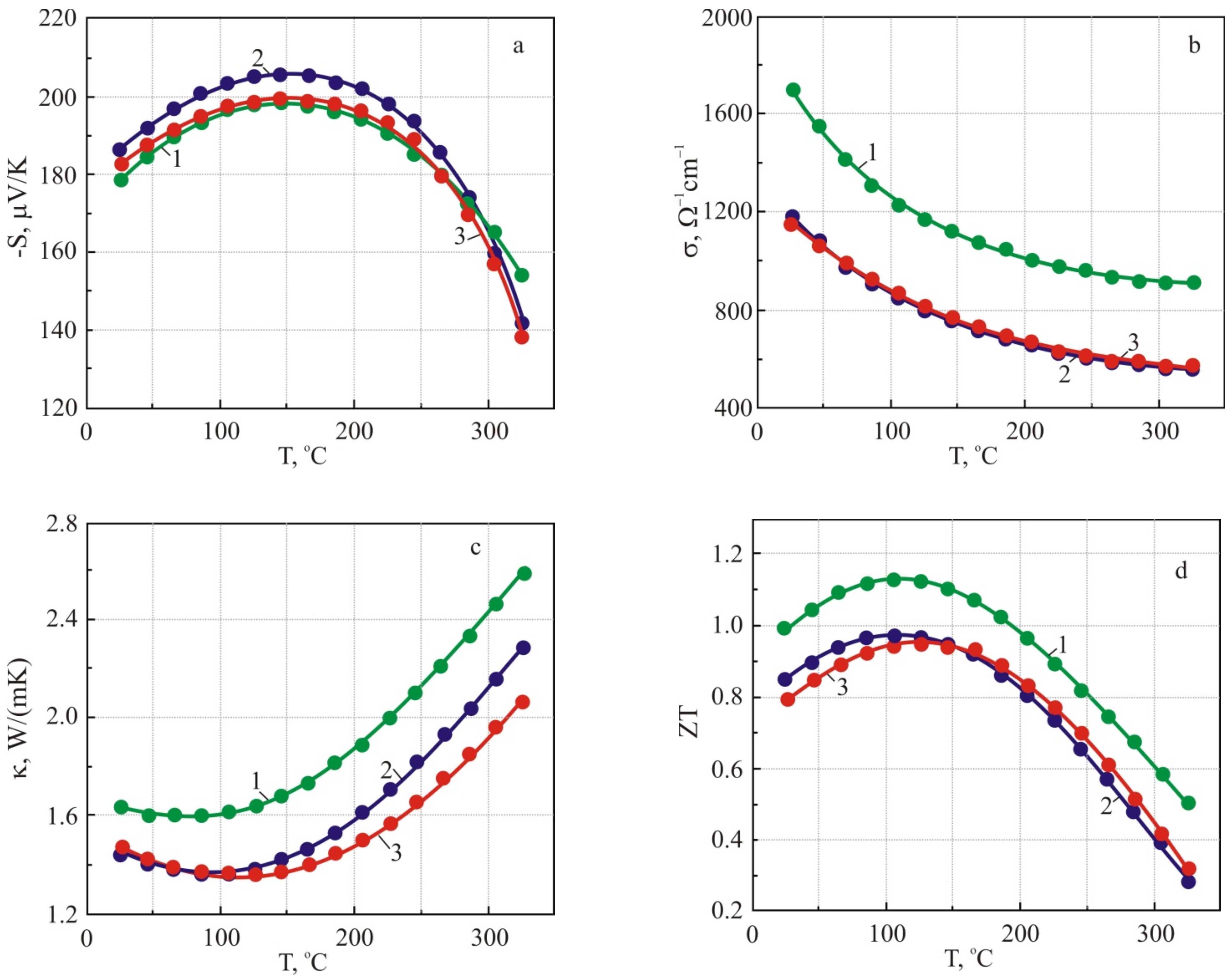
4. Low-Temperature (50–300 °C) Thermoelectric Materials Based on n-Type and p-Type B2Te3 Compounds
4.1. Structure Properties
4.2. Mechanical Properties
4.2.1. N-Type Thermoelectric Materials
4.2.2. P-Type Thermoelectric Materials
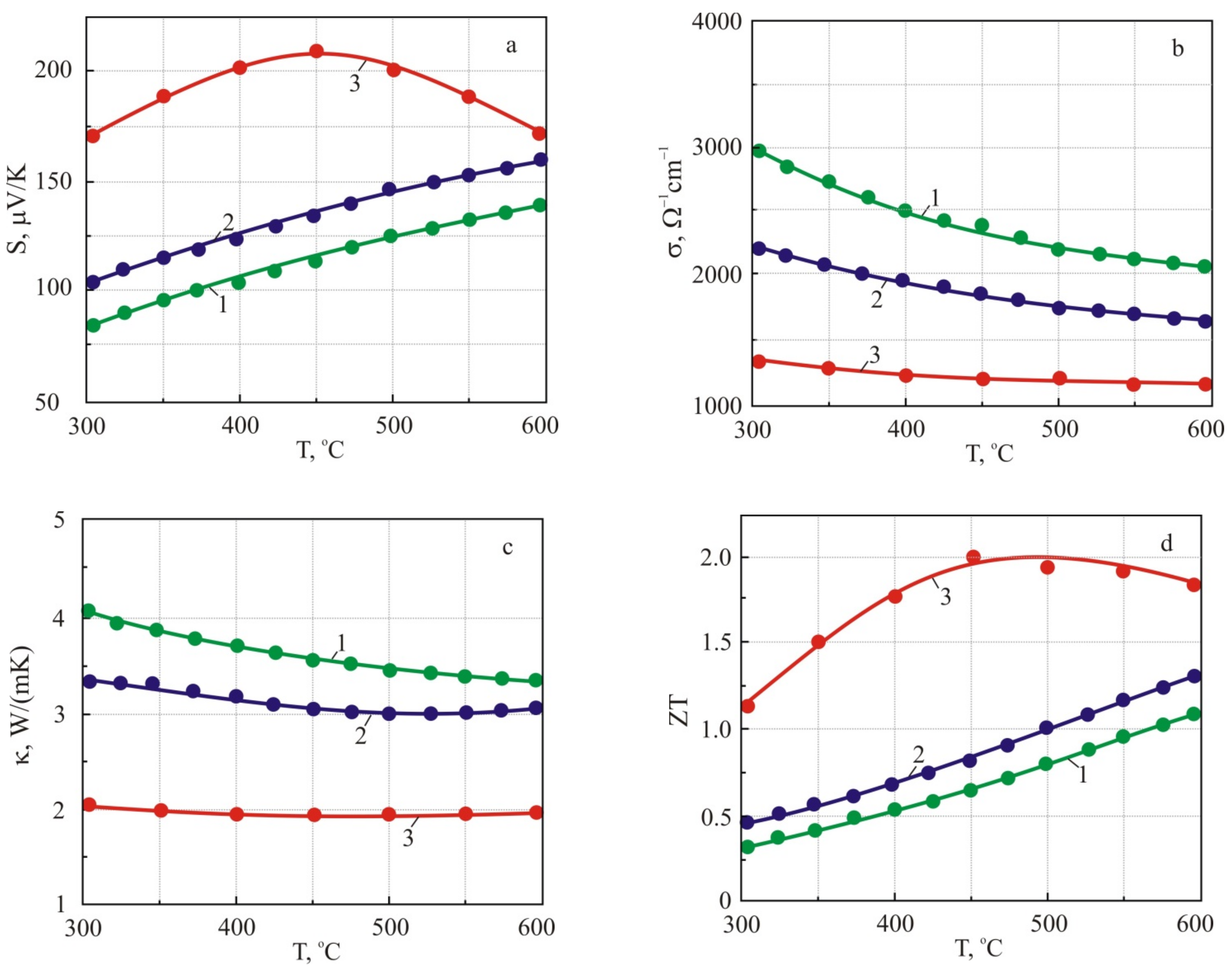
5. Middle-Temperature Thermoelectric Materials (Operating Temperature (300–600 °C)
5.1. Middle-Temperature n-Type Thermoelectric Material Based on In and I-Codoped PbTe semiconductor Compound
5.2. Middle Temperature p-Type Thermoelectric Material Based on GeTe Compound
6. Applications
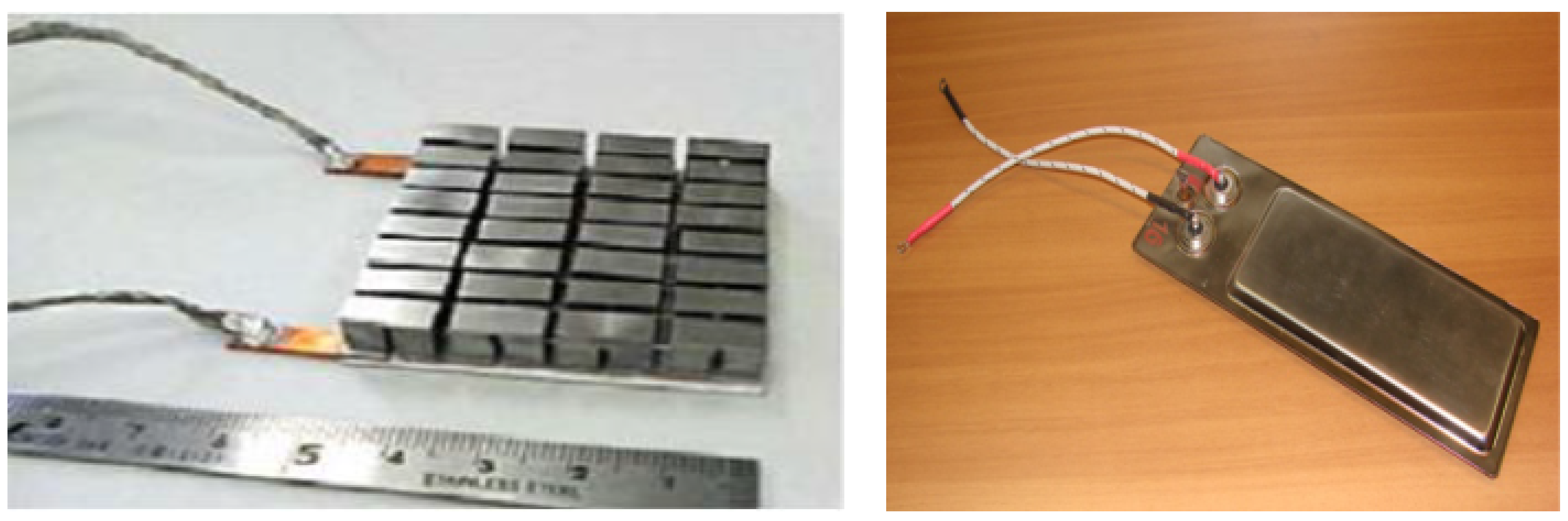
6.1. Thermoelectric Module
- Assembly of the developed TE unicouples and enclosing/placing cold side plates into an aluminum cassette.
- Sintering of the cassette under pressure.
- Formation of a sequential chain of thermoelements.
- Assembly of the TE module in a protective case of stainless-steel thin sheet.
- Sealing of the module, including welding of the cover, rollbacks and argon filling.
6.2. Gas Thermoelectric Generator (TEG)
7. Conclusions
- (a)
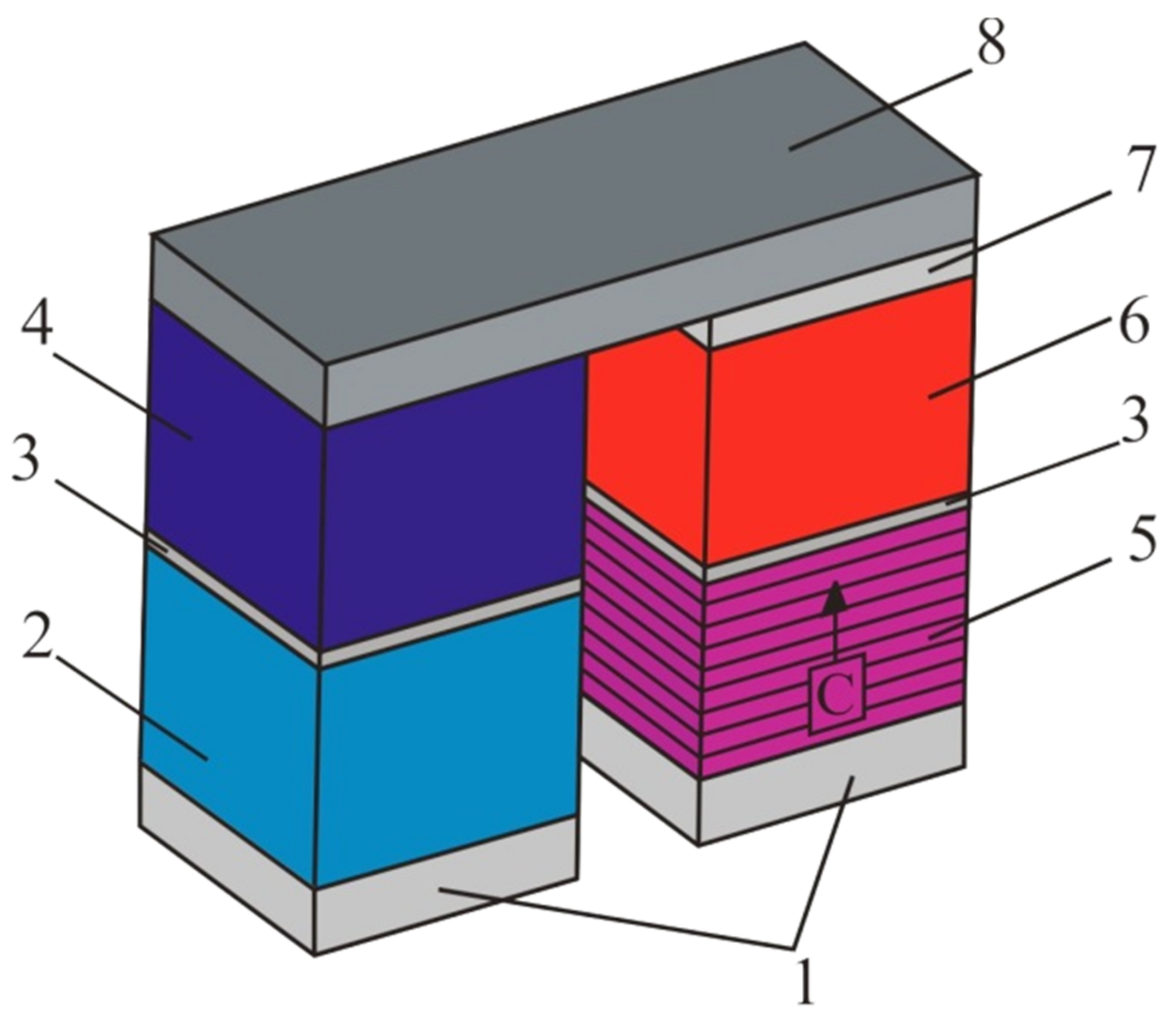
- A unique design for a multilayer (multistage) TE unicouple, which is the main part of the thermoelectric energy module, is developed. Two types of thermoelectric materials were selected: the n- and p-type low-temperature TE materials (with an operating temperature range of 50–300 °C) based on Bi2Te3 compounds with an optimal crystal orientation provided by hot extrusion, and the middle-temperature TE materials (with an operating temperature range of 300–600 °C), which uses the SPS technique to prepare n-type TE material based on PbTe and p-type TE material based on GeTe. The TE outstanding energy conversion efficiency η~15 % was measured for the TE unicouple with a temperature difference ΔT = 550 °C (Th = 600 °C), which is practically the maximum efficiency for TE modules of gas TEGs.
- (b)
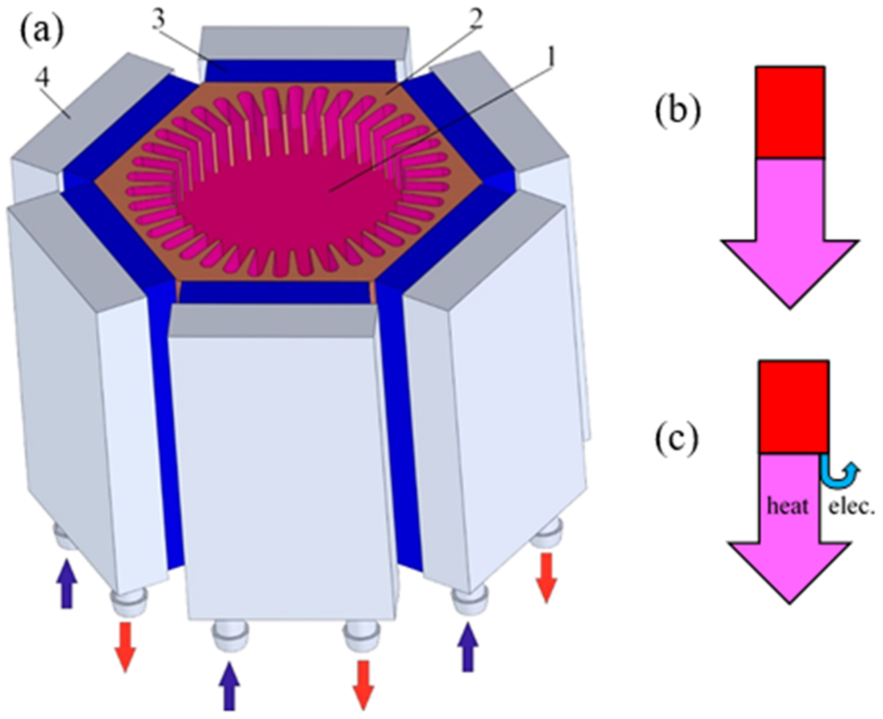
- The possibility of extracting this amount of electrical power from the heat generated for domestic warming, and using the waste heat for water-heating. We suggest using this high-efficiency TEG design in a system combining TEG and a gas boiler into one autonomous source of electrical energy and heat for domestic use. We expect that the prototype of this hybrid system can produce ~400–500 W of electrical energy and 1700–2000 W of heat energy for heating and hot water supply.
Author Contributions
Funding
Institutional Review Board Statement
Informed Consent Statement
Data Availability Statement
Conflicts of Interest
References
- Men, Y.; Liu, X.; Zhang, T. A review of boiler waste heat recovery technologies in the medium-low temperature range. Energy 2021, 237, 121560. [Google Scholar] [CrossRef]
- Row, D.M. (Ed.) CRC Thermoelectrics Handbook: Macro to Nano; CRS Press: London, UK, 2006. [Google Scholar] [CrossRef]
- Chen, J.; Li, K.; Liu, C.; Li, M.; Lv, Y.; Jia, L.; Jiang, S. Enhanced efficiency of thermoelectric generator by optimizing mechanical and electrical Structures. Energies 2017, 10, 1329. [Google Scholar] [CrossRef] [Green Version]
- Böttner, H.; Nurnus, J.; Gavrikov, A.; Kühner, G.; Jägle, M.; Künzel, C.; Eberhard, D.; Plescher, G.; Schubert, A.; Schlereth, K.H. New thermoelectric components using microsystems technologies. J. Microelectromech. Syst. 2004, 13, 414–420. [Google Scholar] [CrossRef]
- Snyder, G.J.; Lim, J.R.; Huang, C.-K.; Fleurial, J.-P. Thermoelectric microdevice fabricated by a MEMS-like electrochemical process. Nat. Mater. 2003, 2, 528–531. [Google Scholar] [CrossRef] [PubMed]
- El Oualid, S.; Kosior, F.; Dauscher, A.; Candolfi, C.; Span, G.; Mehmedovic, E.; Paris, J.; Lenoir, B. Innovative design of bismuth-telluride-based thermoelectric micro-generators with high output power. Energy Environ. Sci. 2020, 13, 3579–3591. [Google Scholar] [CrossRef]
- Maksymuk, M.; Parashchuk, T.; Dzundza, B.; Nykyruy, L.; Chernyak, L.; Dashevsky, Z. Highly efficient bismuth telluride–based thermoelectric microconverters. Mater. Today Energy 2021, 21, 100753. [Google Scholar] [CrossRef]
- Pei, Y.; Shi, X.; LaLonde, A.; Wang, H.; Chen, L.; Snyder, G.J. Convergence of electronic bands for high performance bulk thermoelectrics. Nature 2011, 473, 66–69. [Google Scholar] [CrossRef]
- Zoui, M.A.; Bentouba, S.; Stocholm, J.G.; Bourouis, M. A review on thermoelectric generators: Progress and application. Energies 2020, 13, 3606. [Google Scholar] [CrossRef]
- Oualid, S.; Kogut, I.; Benyahia, M.; Geczi, E.; Kruck, U.; Kosior, F.; Masschelein, P.; Candolfi, C.; Dauscher, A.; Koenig, J.D.; et al. High power density thermoelectric generators with skutterudites. Adv. Energy Mater. 2021, 11, 2100580. [Google Scholar] [CrossRef]
- Hewawasam, L.S.; Jayasena, A.S.; Afnan, M.M.; Ranasinghe, R.A.; Wijewardane, M.A. Waste heat recovery from thermoelectric generators (TEGs). Energy Rep. 2020, 6, 474–479. [Google Scholar] [CrossRef]
- Tohidi, F.; Holagh, S.G.; Chitsaz, A. Thermoelectric Generators: A comprehensive review of characteristics and applications. Appl. Therm. Eng. 2022, 201, 117793. [Google Scholar] [CrossRef]
- Zhang, Z.; Zhang, Y.; Sui, X.; Li, W.; Xu, D. Performance of thermoelectric power-generation system for sufficient recovery and reuse of heat accumulated at cold side of TEG with water-cooling energy exchange circuit. Energies 2020, 13, 5542. [Google Scholar] [CrossRef]
- Dashevsky, Z.; Skipidarov, S. Investigating the Performance of Bismuth-Antimony Telluride. In Novel Thermoelectric Materials and Device Design Concepts; Nikitin, M., Skipidarov, S., Eds.; Springer: Cham, Switzerland; New York, NY, USA, 2019; pp. 3–21. [Google Scholar] [CrossRef]
- Rad, M.K.; Rezania, A.; Omid, M.; Rajabipour, A.; Rosendahl, L.A. Study on material properties effect for maximization of thermoelectric power generation. Renew. Energy 2019, 138, 236–242. [Google Scholar]
- Mamur, H.; Bhuiyan, M.R.A.; Korkmaz, F.; Nil, M. A review on bismuth telluride (Bi2Te3) nanostructure for thermoelectric applications. Renew. Sustain. Energy Rev. 2018, 82, 4159–4169. [Google Scholar] [CrossRef]
- Maksymuk, M.; Dzundza, B.; Matkivsky, O.; Horichok, I.; Shneck, R.; Dashevsky, Z. Development of the high performance thermoelectric unicouple based on Bi2Te3 compounds. J. Power Sources 2022, 530, 231301. [Google Scholar] [CrossRef]
- Gayner, C.; Kar, K.K. Recent advances in thermoelectric materials. Prog. Mater. Sci. 2016, 83, 330–382. [Google Scholar] [CrossRef]
- Sootsman, J.R.; Chung, D.Y.; Kanatzidis, M.G. New and old concepts in thermoelectric materials. Angew. Chem. Int. Ed. 2009, 48, 8616–8639. [Google Scholar] [CrossRef]
- Gelbstein, Y.; Dashevsky, Z.; Dariel, M.P. High performance n-type PbTe-based materials for thermoelectric applications. Phys. B 2005, 363, 96–205. [Google Scholar] [CrossRef]
- Parashchuk, T.; Horichok, I.; Kosonowski, A.; Cherniushok, O.; Wyzga, P.; Cempura, G.; Kruk, A.; Wojciechowski, K.T. Insight into the transport properties and enhanced thermoelectric performance of n-type Pb1−xSbxTe. J. Alloys Comp. 2020, 860, 158355. [Google Scholar] [CrossRef]
- Knura, R.; Parashchuk, T.; Yoshiasab, A.; Wojciechowski, K.T. Origins of low lattice thermal conductivity of Pb1−xSnxTe alloys for thermoelectric applications. Dalton Trans. 2021, 50, 4323. [Google Scholar] [CrossRef]
- Petsagkourakis, I.; Tybrandt, K.; Crispin, X.; Ohkubo, I.; Satoh, N.; Mori, T. Thermoelectric materials and applications for energy harvesting power generation. Sci. Technol. Adv. Mater. 2018, 19, 836–862. [Google Scholar] [CrossRef] [PubMed]
- Parashchuk, T.; Shabaldin, A.; Cherniushok, O.; Konstantinov, G.; Horichok, I.; Burkov, A.; Dashevsky, Z. Enhanced thermoelectric properties of p-type Ge1−xPbxTe alloys due to decrease of lattice thermal conductivity. J. Phys. B 2020, 596, 412397. [Google Scholar] [CrossRef]
- Romanjek, K.; Vesin, S.; Aixala, L.; Baffie, T.; Bernard-Granger, G.; Dufourcq, J. High Perormance Silicon–Germanium-Based Thermoelectric Modules for Gas Exhaust Energy Scavenging. J. Electron. Mater. 2015, 44, 2192–2202. [Google Scholar] [CrossRef]
- Delime-Codrin, K.; Omprakash, M.; Ghodke, S.; Sobota, R.; Adachi, M.; Kiyama, M.; Matsuura, T.; Yamamoto, Y.; Matsunami, M.; Takeuchi, T. Large figure of merit ZT = 1.88 at 873 K achieved with nanostructured Si0.55Ge0.35(P0.10Fe0.01). Appl. Phys. Express 2019, 12, 045507. [Google Scholar] [CrossRef]
- Parashchuk, T.; Sidorenko, N.; Ivantsov, L.; Sorokin, A.; Maksymuk, M.; Dzundza, B.; Dashevsky, Z. Development of a solid-state multi-stage thermoelectric cooler. J. Power Sources 2021, 496, 229821. [Google Scholar] [CrossRef]
- Dashevsky, Z.M.; Kostantinov, P.P.; Skipidarov, S.Y. New way of application for thermoelectric energy converters. Semiconductors 2019, 53, 861–864. [Google Scholar] [CrossRef]
- Lavrentev, M.G.; Drabkin, I.A.; Ershova, L.B.; Volkov, M.P. Improved extruded thermoelectric materials. J. Elec. Mater. 2020, 49, 2937–2942. [Google Scholar] [CrossRef]
- Sorokin, A.I.; Ivantsov, M.S.; Tabachkova, N.Y.; Bublik, V.T.; Skipidarov, S.Y.; Dashevsky, Z.M. Development of technology for high-strength thermoelectrics with a diameter of up to 35 mm based on Bi2Te3 polycrystals by hot extrusion. Fiz. Tekh. Poluprovodn. 2022, 56, 17–21. [Google Scholar]
- Wojciechowski, K.T.; Parashchuk, T.; Wiendlocha, B.; Cherniushok, O.; Dashevsky, Z. Highly efficient n-type PbTe developed by advanced electronic structure engineering. J. Mater. Chem. C 2020, 8, 13270–13285. [Google Scholar] [CrossRef]
- Srinivasan, B.; Gautier, R.; Gucci, F.; Fontaine, B.; Halet, J.-F.; Cheviré, F.; Boussard-Plédel, C.; Reece, M.J.; Bureau, B. Impact of Coinage Metal Insertion on the Thermoelectric Properties of GeTe Solid-State Solutions. J. Phys. Chem. C Am. Chem. Soc. 2018, 122, 227–235. [Google Scholar] [CrossRef]
- Dashevsky, Z.; Horichok, I.; Maksymuk, M.; Muchtar, A.R.; Srinivasan, B.; Mori, T. Feasibility of high performance in p-type Ge1− xBixTe materials for thermoelectric modules. J. Am. Ceram. Soc. 2022, 105, 4500–4511. [Google Scholar] [CrossRef]
- Kostyuk, O.; Dzundza, B.; Maksymuk, M.; Bublik, V.; Chernyak, L.; Dashevsky, Z. Development of Spark Plasma Syntering (SPS) technology for preparation of nanocrystalline p-type thermoelctrics based on (BiSb)2Te3. Phys. Chem. Solid State 2020, 21, 628–634. [Google Scholar] [CrossRef]
- Callister, W.D., Jr. Materials Science and Engineering, 6th ed.; John Wiley & Sons, Inc.: Hoboken, NJ, USA, 2003. [Google Scholar]
- Parashchuk, T.; Dashevsky, Z.; Wojciechowski, K. Feasibility of a high stable PbTe:In semiconductor for thermoelectric energy applications. J. Appl. Phys. 2019, 125, 245103. [Google Scholar] [CrossRef]
- Seo, J.; Lee, C.; Park, K. Thermoelectric properties of n-type SbI3-doped Bi2Te2.85Se0.15 compound fabricated by hot pressing and hot extrusion. J. Mater. Sci. 2000, 35, 1549–1554. [Google Scholar] [CrossRef]
- Bomshtein, N.; Spiridonov, G.; Dashevsky, Z.; Gelbstien, Y. Thermoelectric, structural, and mechanical properties of Spark-Plasma-Sintered submicro- and microstructured p-type Bi0.5Sb1.5Te3. J. Electron. Mater. 2012, 41, 1546–1553. [Google Scholar] [CrossRef]
- Prokofieva, L.V.; Pshenay-Severin, D.A.; Konstantinov, P.P.; Shabaldin, A.A. Optimum composition of a Bi2Te3−xSex alloy for the n-type leg of a thermoelectric generator. Semiconductors 2009, 43, 973–976. [Google Scholar] [CrossRef]
- Witting, I.T.; Ricci, F.; Chasapis, T.C.; Hautier, G.; Snyder, G.J. The Thermoelectric Properties of n-Type Bismuth Telluride: Bismuth Selenide Alloys Bi2Te3−xSex. Research 2020, 2020, 4361703. [Google Scholar] [CrossRef] [Green Version]
- Goltsman, B.M.; Kudinov, V.A.; Smirnov, I.A. Thermoelectric Semiconductor Materials Based on Bi2Te3; Nauka: Moskow, Russia, 1972. (In Russian) [Google Scholar]
- Gelbstein, Y.; Gotesman, G.; Lishzinker, Y.; Dashevsky, Z.; Dariel, M.P. Mechanical properties of PbTe—Based thermoelectric semiconductors. Scr. Mater. 2008, 58, 251–254. [Google Scholar] [CrossRef]
- Gelbstein, Y.; Dashevsky, Z.; Dariel, M.P. The search for mechanically stable PbTe based thermoelectric materials. J. Appl. Phys. 2008, 104, 33–40. [Google Scholar] [CrossRef]
- Male, J.P.; Abdellaoui, L.; Yu, Y.; Zhang, S.; Pieczulewski, N.; Cojocaru-Miredin, O.; Scheu, C.; Snyder, G. Dislocations stabilized by point defects increase brittleness in PbTe. Adv. Funct. Mater. 2021, 2108006, 1–9. [Google Scholar] [CrossRef]
- Zhang, G.; Fan, L.; Niu, Z.; Jiao, K.; Diao, H.; Du, Q.; Shu, G. A comprehensive design method for segmented thermoelectric generator. Energy Convers. Manag. 2015, 106, 510–519. [Google Scholar] [CrossRef]
- Dughaish, Z. Lead telluride as a thermoelectric material for thermoelectric power generation. J. Phys. B 2002, 322, 205–223. [Google Scholar] [CrossRef]
- LaLonde, A.D.; Pei, Y.; Wang, H.; Snyder, G.J. Lead telluride alloy thermoelectrics. Mater. Today 2011, 14, 526–532. [Google Scholar] [CrossRef]
- Dariel, M.P.; Dashevsky, Z.; Jarashnely, A.; Shusterman, S.; Horowitz, A. Carrier concentration gradient generated in p-type PbTe crystals by unidirectional solidification. J. Cryst. Growth 2002, 234, 164–170. [Google Scholar] [CrossRef]
- Kim, Y.J.; Zhao, L.-D.; Kanatzidis, M.G.; Seidman, D. Analysis of nanoprecipitates in a Na-doped PbTe–SrTe thermoelectric material with a high figure of merit. Appl. Mater. Interfaces 2017, 9, 21791–21797. [Google Scholar] [CrossRef]
- Androulakis, J.; Todorov, I.; Chung, D.-Y.; Ballikaya, S.; Wang, G.; Uher, C.; Kanatzidis, M. Thermoelectric enhancement in PbTe with K or Na codoping from tuning the interaction of the light- and heavy-hole valence bands. Phys. Rev. B 2010, 82, 115209. [Google Scholar] [CrossRef] [Green Version]
- Jood, P.; Male, J.P.; Anand, S.; Matsushita, Y.; Takagiwa, Y.; Kanatzidis, M.G.; Snyder, G.J.; Ohta, M. Na doping in PbTe: Solubility, band convergence, phase boundary mapping, and thermoelectric properties. J. Am. Chem. Soc. 2020, 142, 15464–15475. [Google Scholar] [CrossRef]
- Parashchuk, T.; Wiendlocha, B.; Cherniushok, O.; Knura, R.; Wojciechowski, K.T. High thermoelectric performance of p-Type PbTe enabled by the synergy of resonance scattering and lattice softening. ACS Appl. Mater. Interfaces 2021, 13, 49027–49042. [Google Scholar] [CrossRef]
- Kaidanov, V.I.; Ravich, Y.I. Deep and resonance states in AIVBVI semiconductors. Sov. Phys. Usp. 1985, 28, 31–53. [Google Scholar] [CrossRef]
- Kaidanov, V.I. Resonance (Quasilocal) states in AIVBVI semiconductors. Defect Diffus. Forum 1993, 103–105, 387–406. [Google Scholar] [CrossRef]
- Dashevsky, Z.; Shusterman, S.; Dariel, M.P.; Drabkin, I. Thermoelectric efficiency in graded indium-doped PbTe crystals. J. Appl. Phys. 2002, 92, 1425–1430. [Google Scholar] [CrossRef]
- Heremans, J.P.; Wiendlocha, B.; Chamoire, A.M. Resonant levels in bulk thermoelectric semiconductors. Energy Environ. Sci. 2012, 5, 55105530. [Google Scholar] [CrossRef]
- Bali, A.; Chetty, R.; Sharma, A.; Rogl, G.; Heinrich, P.; Suwas, S.; Misra, D.K.; Rogl, P.; Bauer, E.; Mallik, R.C. Thermoelectric properties of In and I doped PbTe. J. Appl. Phys. 2016, 120, 175101. [Google Scholar] [CrossRef]
- Dashevsky, Z.; Dudkin, L. Generator thermoelectric materials. J. Thermoelectr. 1993, 1, 93–106. [Google Scholar]


| No. | Composition | Technology | Fb, N | yb, mm | σb, MPa |
|---|---|---|---|---|---|
| 1 | n-type Bi2Te2.7Se0.3 | Hot extrusion | 86.1 | 0 | 36.6 |
| 2 | p-type Bi0.5Sb1.5Te3 | Hot extrusion | 81.8 | 0 | 28.2 |
| 3 | p-type Bi0.5Sb1.5Te3 | Zone float | >10 | 0 | >3.5 |
| 4 | n-type Bi2Te2.7Se0.3 | Zone float | - | - | - |
| Composition | Technology | Force, F, N | σc, MPa | |
|---|---|---|---|---|
| 1 | p-type Bi0.5Sb1.5Te3 | Hot extrusion | 1782.0 | 71.3 |
| 2 | p-type Bi0.5Sb1.5Te3 | Hot extrusion | 1940.0 | 77.9 |
| 3 | p-type Bi0.5Sb1.5Te3 | Hot extrusion | 1998.0 | 80.7 |
| 4 | n-type Bi2Te2.7Se0.3 | Hot extrusion | 2980.0 | 119.4 |
| 5 | n-type Bi2Te2.7Se0.3 | Hot extrusion | 2749.4 | 107.8 |
| 6 | n-type Bi2Te2.7Se0.3 | Hot extrusion | 2877.4 | 122.9 |
| 7 | p-type Bi0.5Sb1.5Te3 | Zone float | 200.0 | 7.9 |
| 8 | p-type Bi0.5Sb1.5Te3 | Zone float | 285.0 | 11.9 |
| 9 | n-type Bi2Te2.7Se0.3 | Zone float | 431.7 | 17.6 |
| 10 | n-type Bi2Te2.7Se0.3 | Zone float | 352.3 | 14.2 |
Publisher’s Note: MDPI stays neutral with regard to jurisdictional claims in published maps and institutional affiliations. |
© 2022 by the authors. Licensee MDPI, Basel, Switzerland. This article is an open access article distributed under the terms and conditions of the Creative Commons Attribution (CC BY) license (https://creativecommons.org/licenses/by/4.0/).
Share and Cite
Dashevsky, Z.; Jarashneli, A.; Unigovski, Y.; Dzunzda, B.; Gao, F.; Shneck, R.Z. Development of a High Perfomance Gas Thermoelectric Generator (TEG) with Possibible Use of Waste Heat. Energies 2022, 15, 3960. https://doi.org/10.3390/en15113960
Dashevsky Z, Jarashneli A, Unigovski Y, Dzunzda B, Gao F, Shneck RZ. Development of a High Perfomance Gas Thermoelectric Generator (TEG) with Possibible Use of Waste Heat. Energies. 2022; 15(11):3960. https://doi.org/10.3390/en15113960
Chicago/Turabian StyleDashevsky, Zinovi, Albert Jarashneli, Yaakov Unigovski, Bohdan Dzunzda, Feng Gao, and Roni Z. Shneck. 2022. "Development of a High Perfomance Gas Thermoelectric Generator (TEG) with Possibible Use of Waste Heat" Energies 15, no. 11: 3960. https://doi.org/10.3390/en15113960
APA StyleDashevsky, Z., Jarashneli, A., Unigovski, Y., Dzunzda, B., Gao, F., & Shneck, R. Z. (2022). Development of a High Perfomance Gas Thermoelectric Generator (TEG) with Possibible Use of Waste Heat. Energies, 15(11), 3960. https://doi.org/10.3390/en15113960