Analysis of High-Frequency Common Mode Component Characteristics of Common Mode Peak Voltage Suppression Method for Indirect Matrix Converter
Abstract
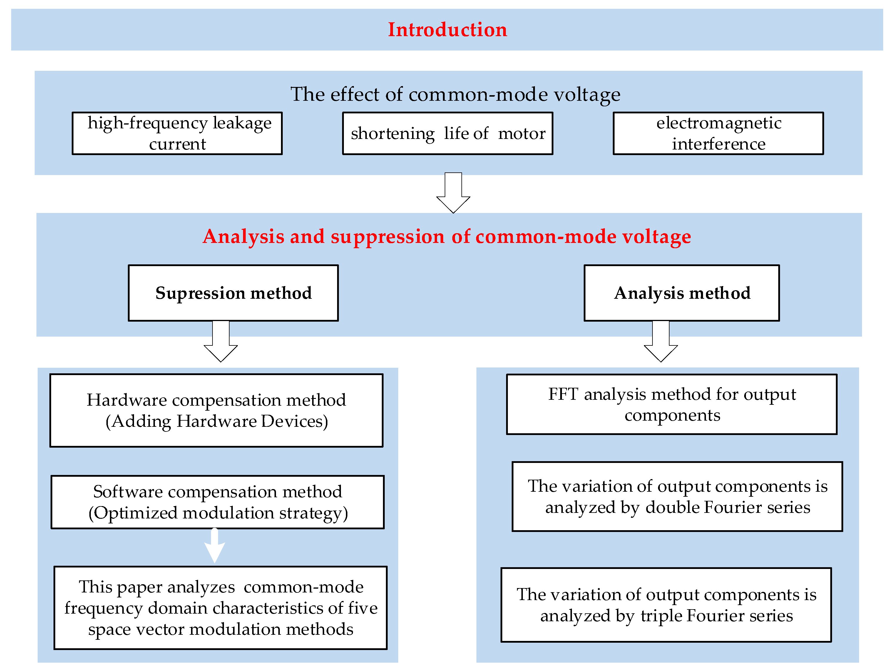
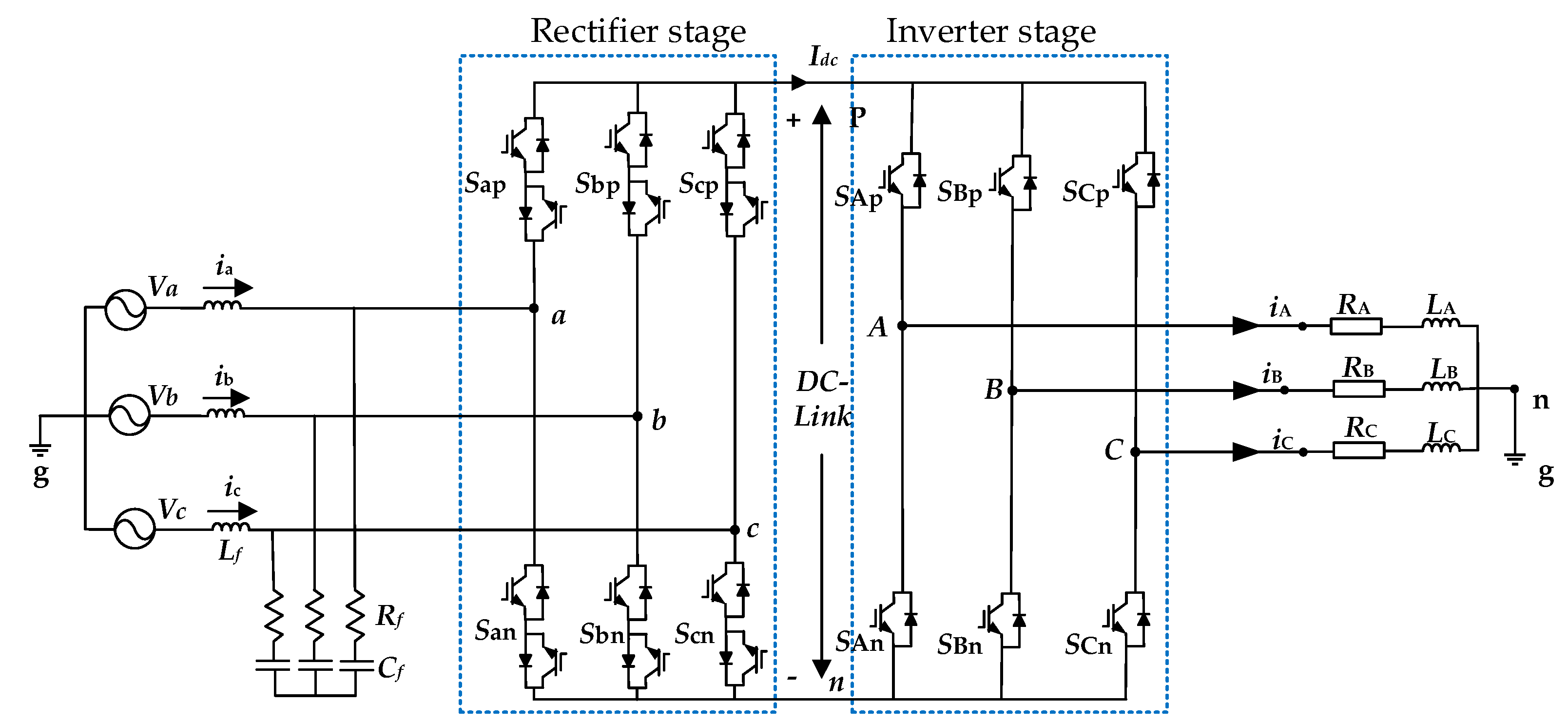
:1. Introduction
2. Triple Fourier Modeling of Common-Mode Voltage of Space Vector Modulation
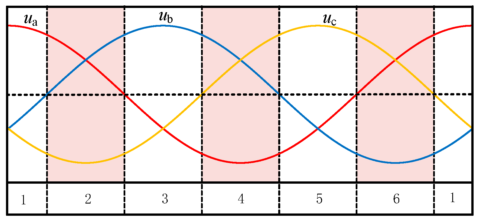
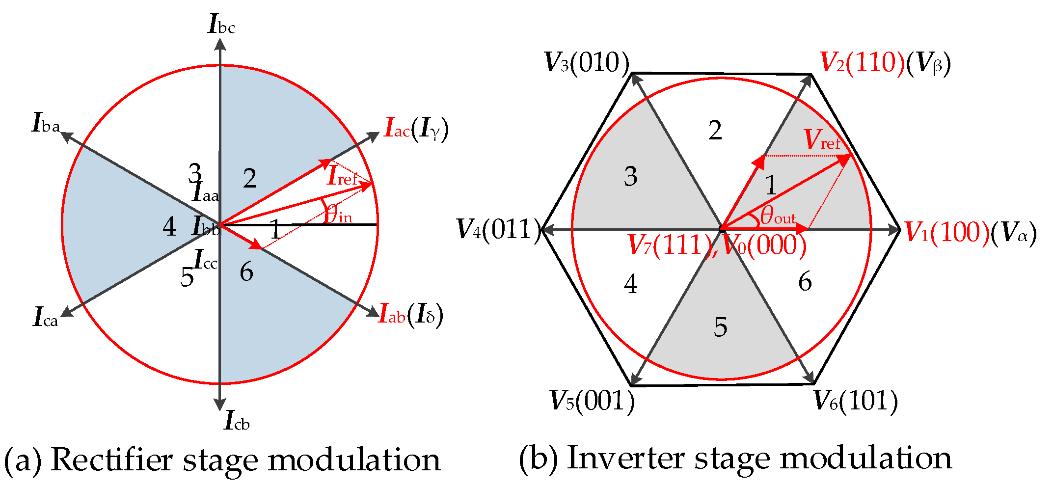
2.1. Traditional Space Vector Modulation
2.2. Modulation Methods to Suppress 42.3% Common-Mode Voltage Peaks
2.2.1. Method 1
2.2.2. Method 2
2.2.3. Method 3
2.2.4. Method 4
2.2.5. Method 5
2.3. Triple Fourier Modeling of Output Common-Mode Voltages
3. Theoretical Analysis and Comparison of Common-Mode Components
3.1. Analysis and Comparison of Common-Mode Components in Low VTR Range
3.2. Analysis and Comparison of Common-Mode Components in High VTR Range
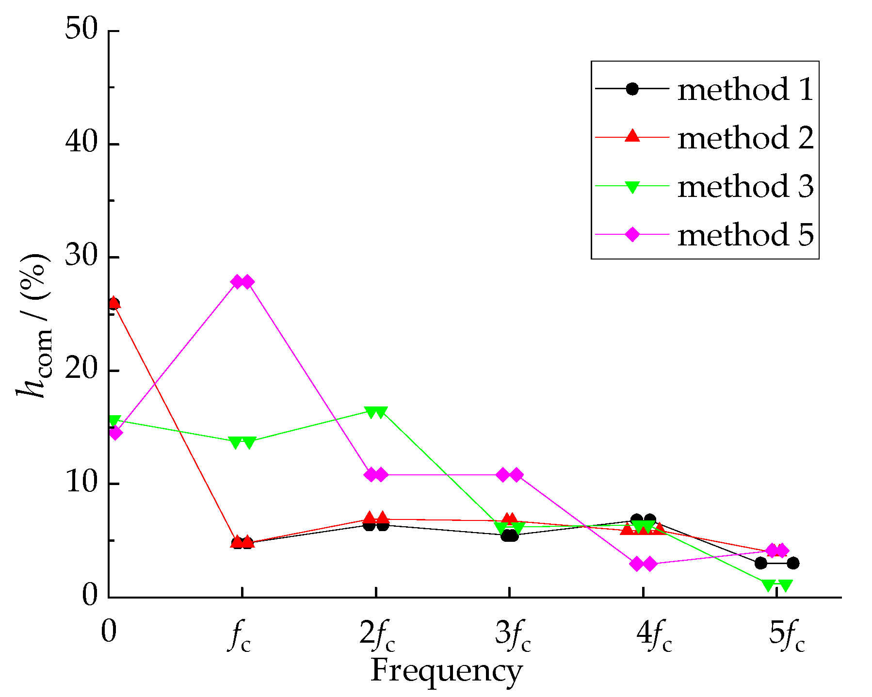
3.3. Frequency Domain Characteristic Analysis of Common-Mode Components of Voltage Transmission Ratio
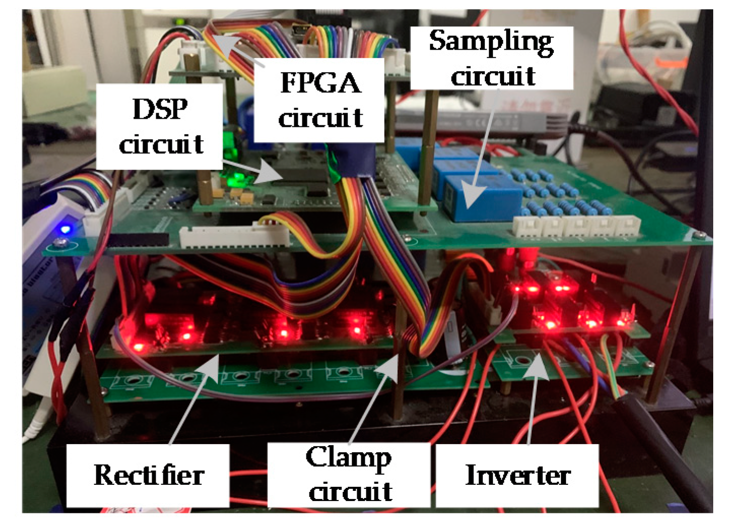
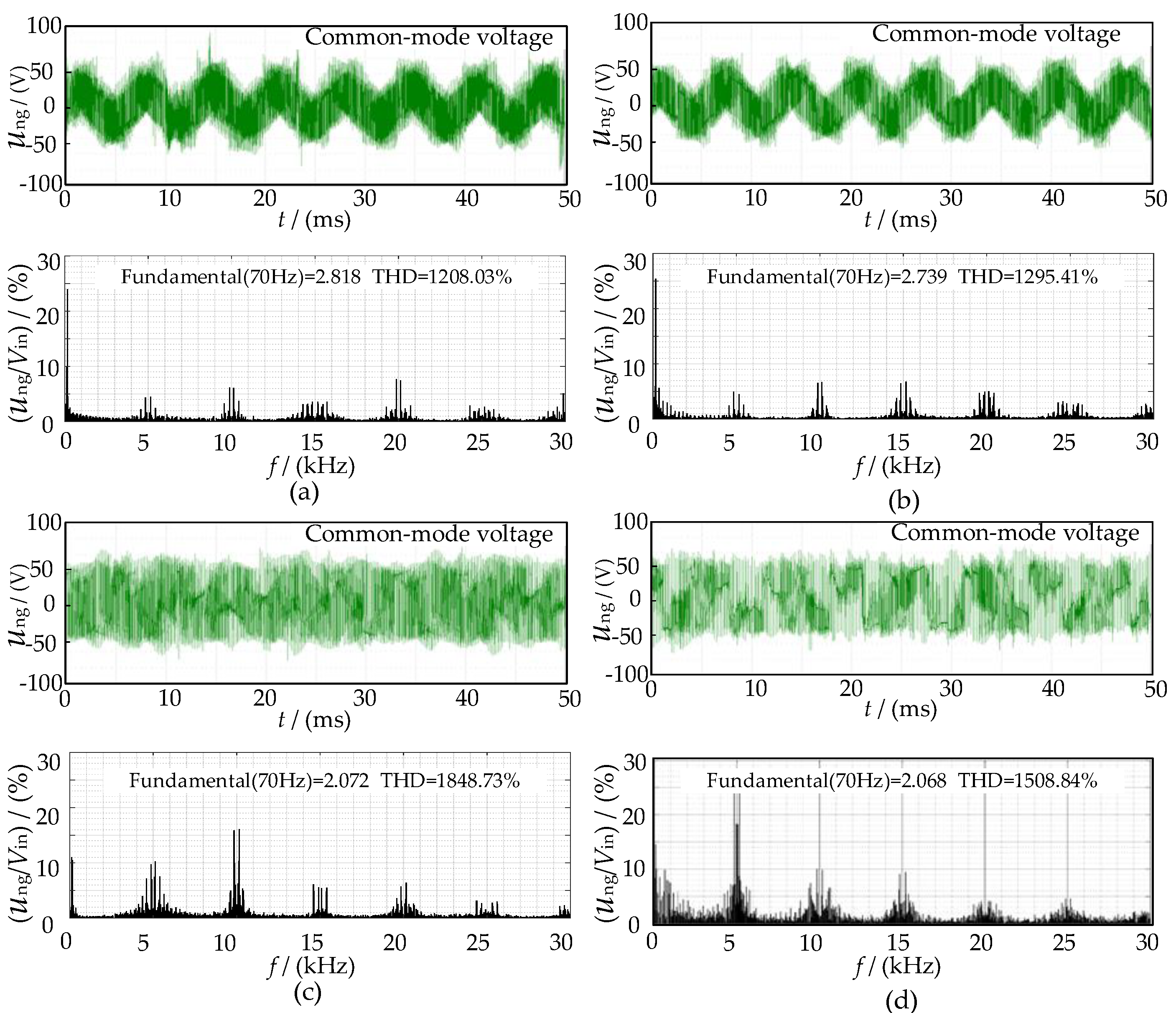
4. Experimental Analysis and Validation
5. Conclusions
Author Contributions
Funding
Institutional Review Board Statement
Informed Consent Statement
Data Availability Statement
Acknowledgments
Conflicts of Interest
References
- Wheeler, P.W.; Rodriguez, J.; Clare, J.C.; Empringham, L.; Weinstein, A. Matrix converters: A technology review. IEEE Trans. Ind. Electron. 2002, 49, 276–288. [Google Scholar] [CrossRef]
- Lee, M.; Wheeler, P.; Klumpner, C. Space-vector modulated multilevel matrix converter. IEEE Trans. Ind. Electron. 2010, 57, 3385–3394. [Google Scholar] [CrossRef]
- Ayano, H.; Murakami, K.; Matsui, Y. A Novel Technique for Reducing Leakage Current by Application of Zero-Sequence Voltage. IEEE Trans. Ind. Appl. 2015, 51, 3094–3100. [Google Scholar] [CrossRef]
- Cao, S.; Niu, F.; Huang, X. Time–frequency characteristics research of common mode current in PWM motor system. IEEE Trans. Power. Electron. 2020, 35, 1450–1458. [Google Scholar] [CrossRef]
- Turzynski, M.; Chrzan, P.J. Reducing Common-Mode Voltage and Bearing Currents in Quasi-Resonant DC-Link Inverter. IEEE Trans. Power Electron. 2020, 35, 9553–9562. [Google Scholar] [CrossRef]
- Takahashi, S.; Ogasawara, S.; Takemoto, M.; Orikawa, K.; Tamate, M. Common-Mode Voltage Attenuation of an Active Common-Mode Filter in a Motor Drive System Fed by a PWM Inverter. IEEE Trans. Ind. Appl. 2019, 55, 2721–2730. [Google Scholar] [CrossRef]
- Jayaraman, K.; Kumar, M. Design of Passive Common-Mode Attenuation Methods for Inverter-Fed Induction Motor Drive with Reduced Common-Mode Voltage PWM Technique. IEEE Trans. Power Electron. 2020, 35, 2861–2870. [Google Scholar] [CrossRef]
- Nguyen, T.; Lee, H. Modulation strategies to reduce common-mode voltage for indirect matrix converters. IEEE Trans. Ind. Electron. 2012, 59, 129–140. [Google Scholar] [CrossRef]
- Nguyen, T.; Lee, H. A new SVM method for an indirect matrix converter with common-mode voltage reduction. IEEE Trans. Ind. Inform. 2014, 10, 61–72. [Google Scholar] [CrossRef]
- Padhee, V.; Sahoo, A.; Mohan, N. Modulation techniques for enhanced reduction in common-mode voltage and output voltage distortion in indirect matrix converters. IEEE Trans. Power Electron. 2017, 32, 8655–8670. [Google Scholar] [CrossRef]
- Tsoupos, A.; Khadkikar, V. A novel SVM technique with enhanced output voltage quality for indirect matrix converters. IEEE Trans. Ind. Electron. 2019, 66, 832–841. [Google Scholar] [CrossRef]
- Li, S.; Jin, Z.; Liu, X.; Han, X.; Deng, W. Open-current vector based SVM strategy of sparse matrix converter for common-mode voltage reduction. IEEE Trans. Ind. Electron. 2021, 68, 7757–7767. [Google Scholar] [CrossRef]
- Li, S.; Wang, W.; Han, X. A DPWM modulation strategy to reduce common-mode voltage for indirect matrix converters based on active-current vector amplitude characteristics. IEEE Trans. Ind. Electron. 2022, 69, 8102–8112. [Google Scholar] [CrossRef]
- Wang, H.; Su, M.; Sun, Y. Topology and modulation scheme of a three-level third-harmonic injection indirect matrix converter. IEEE Trans. Ind. Electron. 2017, 64, 7612–7622. [Google Scholar] [CrossRef]
- Jiang, X.; Xiao, X.; Liu, H. The output spectrum analysis of high-power multilevel voltage source converters using double Fourier series. In Proceedings of the Transmission & Distribution Conference & Exposition, Dalian, China, 18 August 2005; pp. 1–5. [Google Scholar]
- Li, S.; Xia, C.; Yan, Y. Space-vector overmodulation strategy for ultrasparse matrix converter based on the maximum output voltage vector. IEEE Trans. Power Electron. 2017, 32, 5388–5397. [Google Scholar] [CrossRef]
- Wang, B.; Sherif, E. Analytical characterization of the spectral performance of matrix converters. In Proceedings of the International Power Electronics and Motion Control Conference, Harbin, China, 2–5 June 2012; pp. 678–682. [Google Scholar]
- Qiu, L.; Xu, L.; Li, Y. Spectral analysis of a scalar modulated matrix converter based on 3-D Fourier integral. In Proceedings of the European Conference on Power Electronics and Applications, Warsaw, Poland, 11–14 September 2017; pp. 1–8. [Google Scholar]
- Shi, T.; Wu, L.; Yan, Y.; Xia, C. Harmonic spectrum of output voltage for space vector-modulated matrix converter based on triple fourier series. IEEE Trans. Power Electron. 2018, 33, 10646–10653. [Google Scholar] [CrossRef]
- Shi, T.; Wu, L.; Yan, Y.; Xia, C. Harmonic spectrum of output voltage for space vector pulse width modulated ultra sparse matrix converter. Energies 2018, 11, 390. [Google Scholar] [CrossRef] [Green Version]
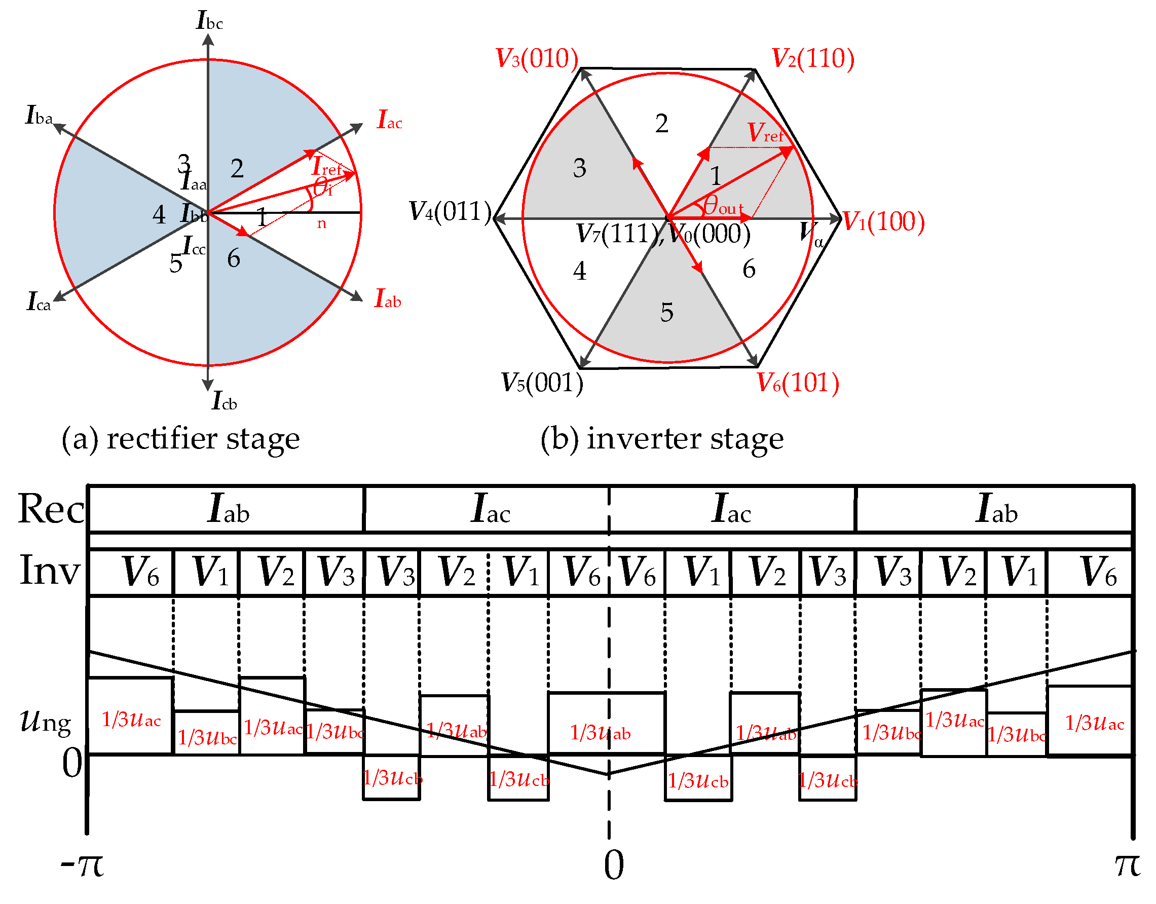
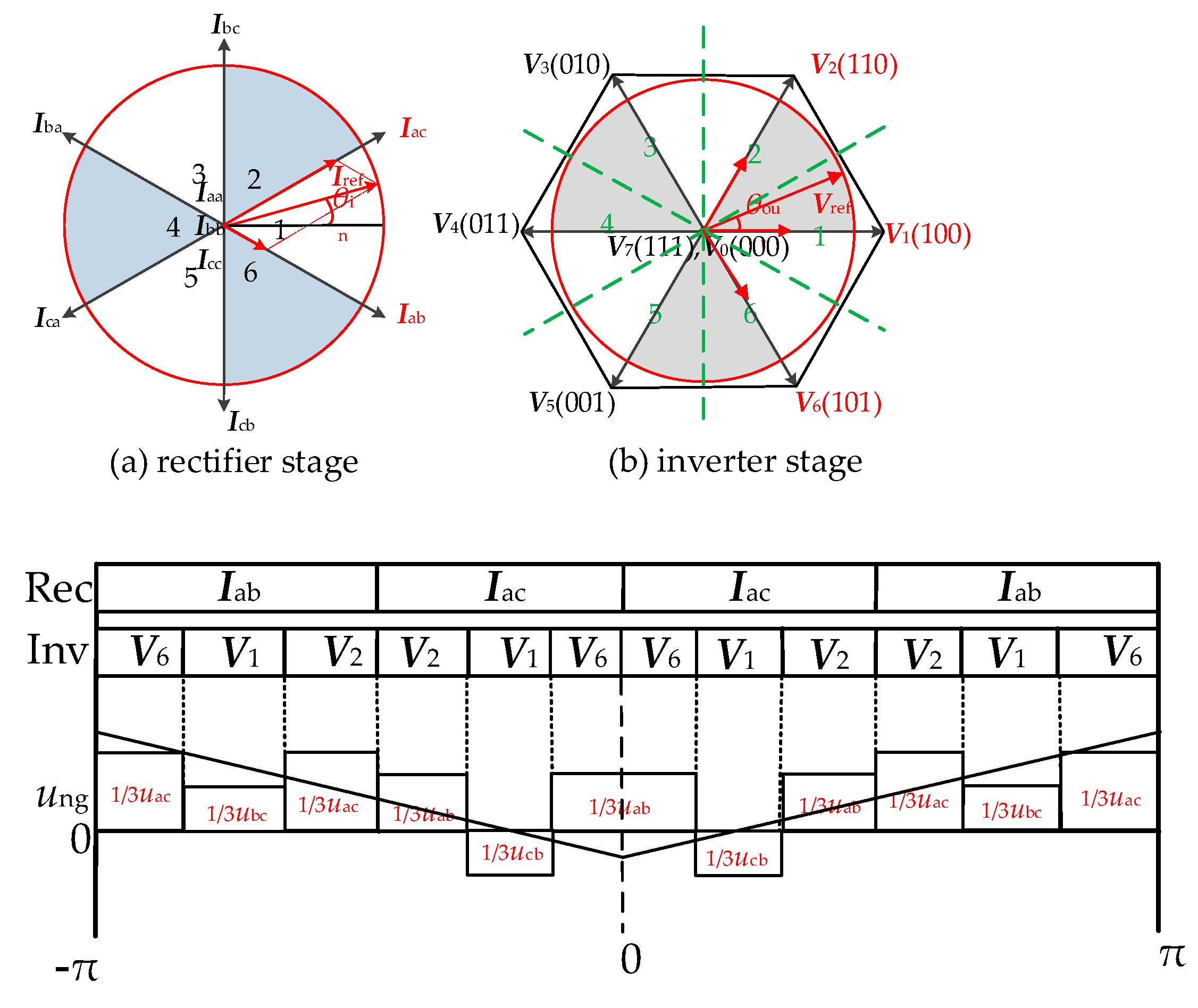
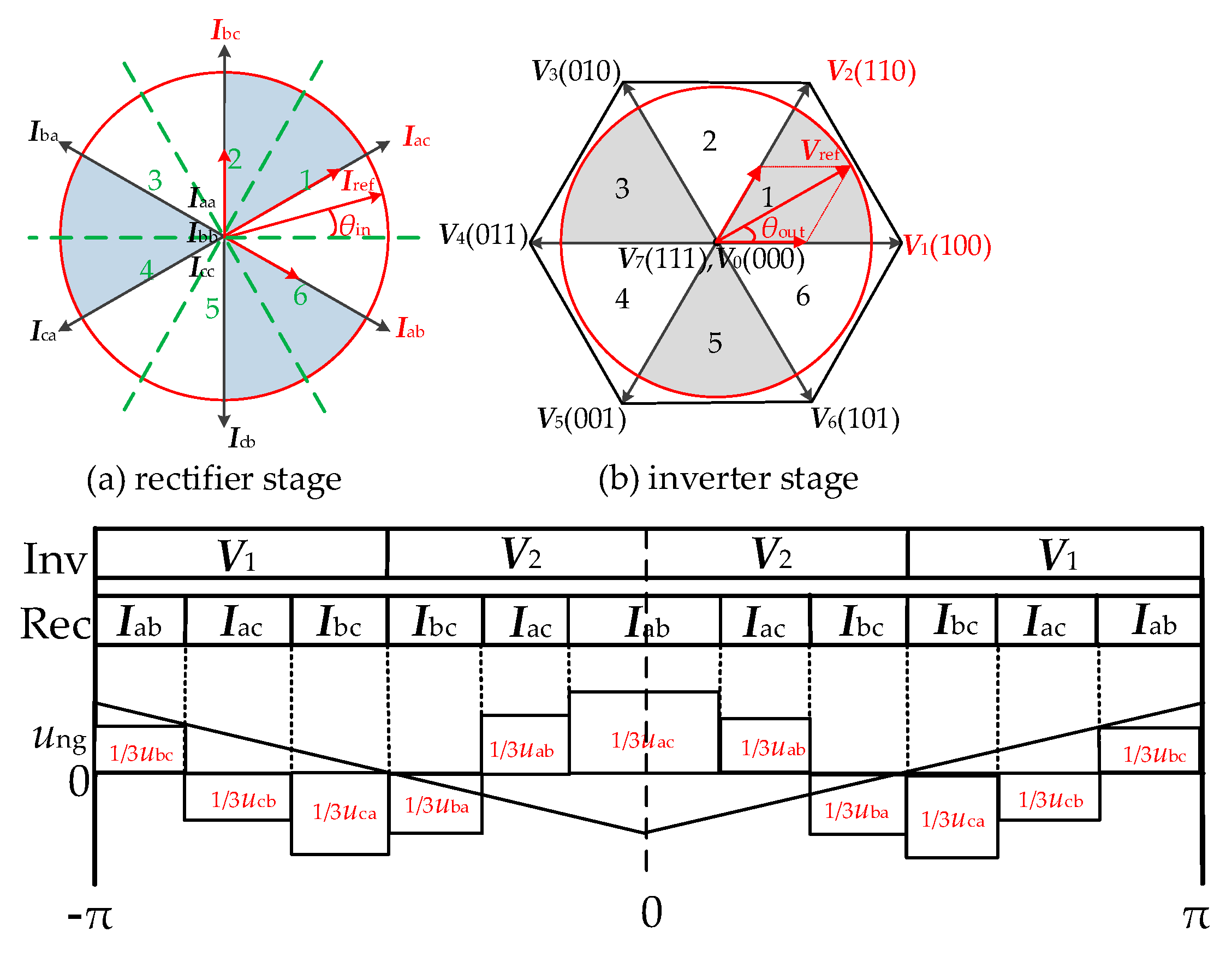
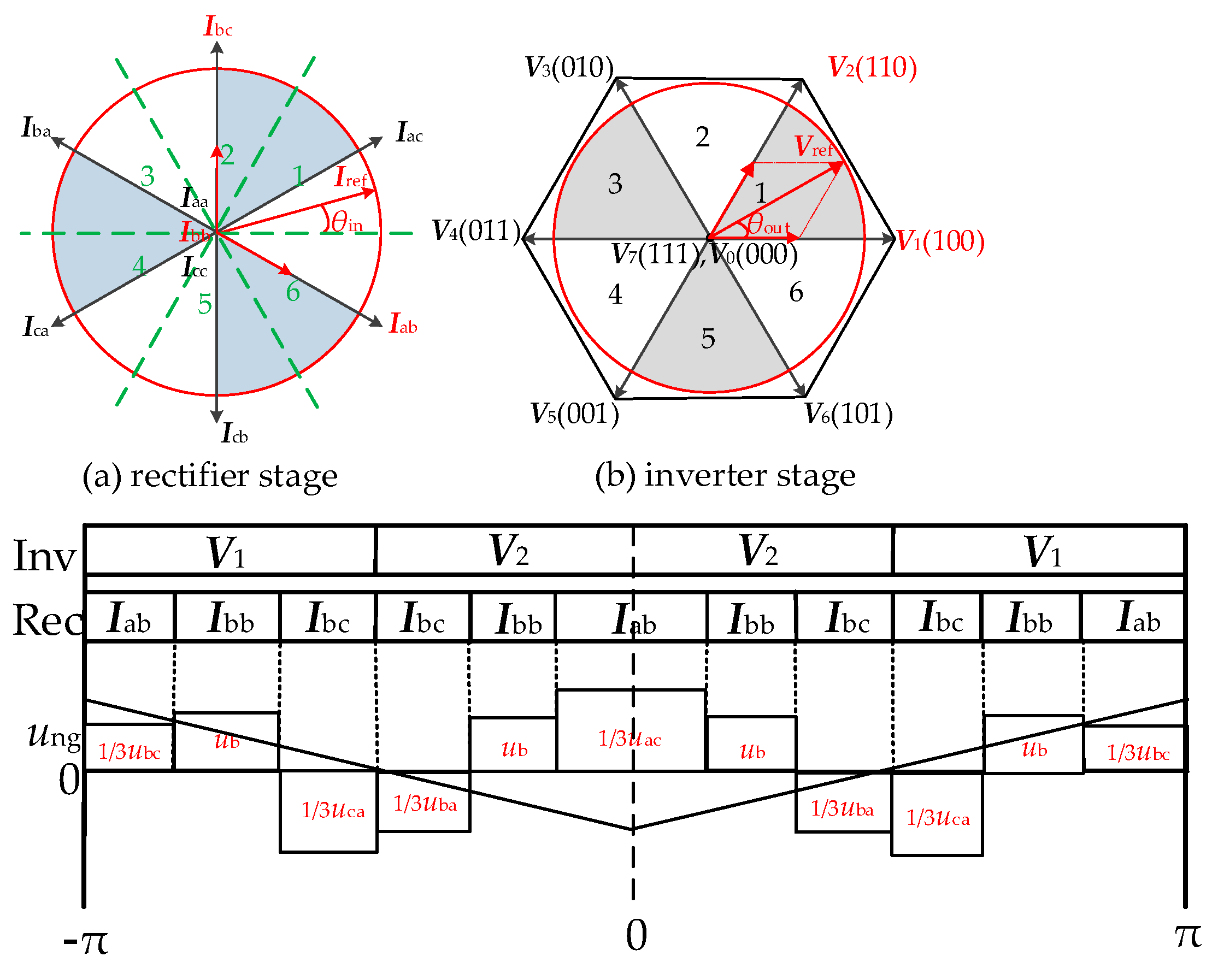

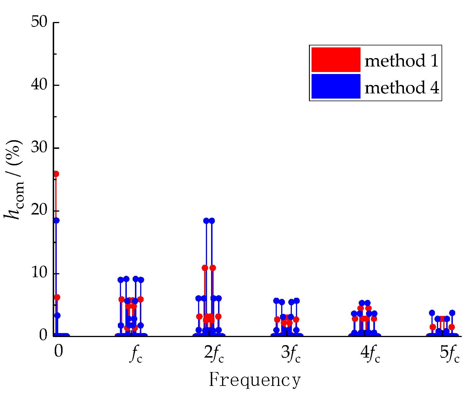
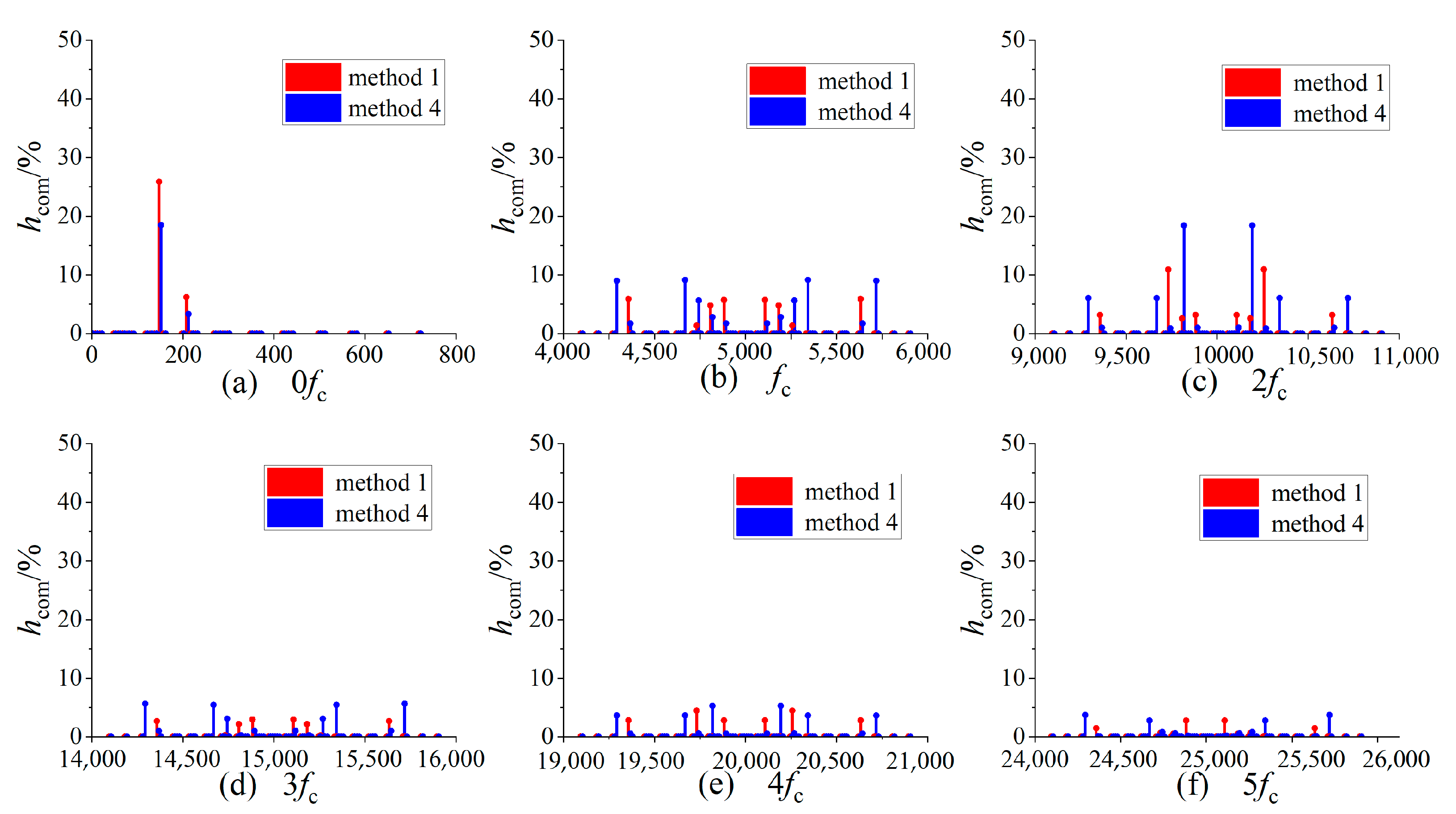

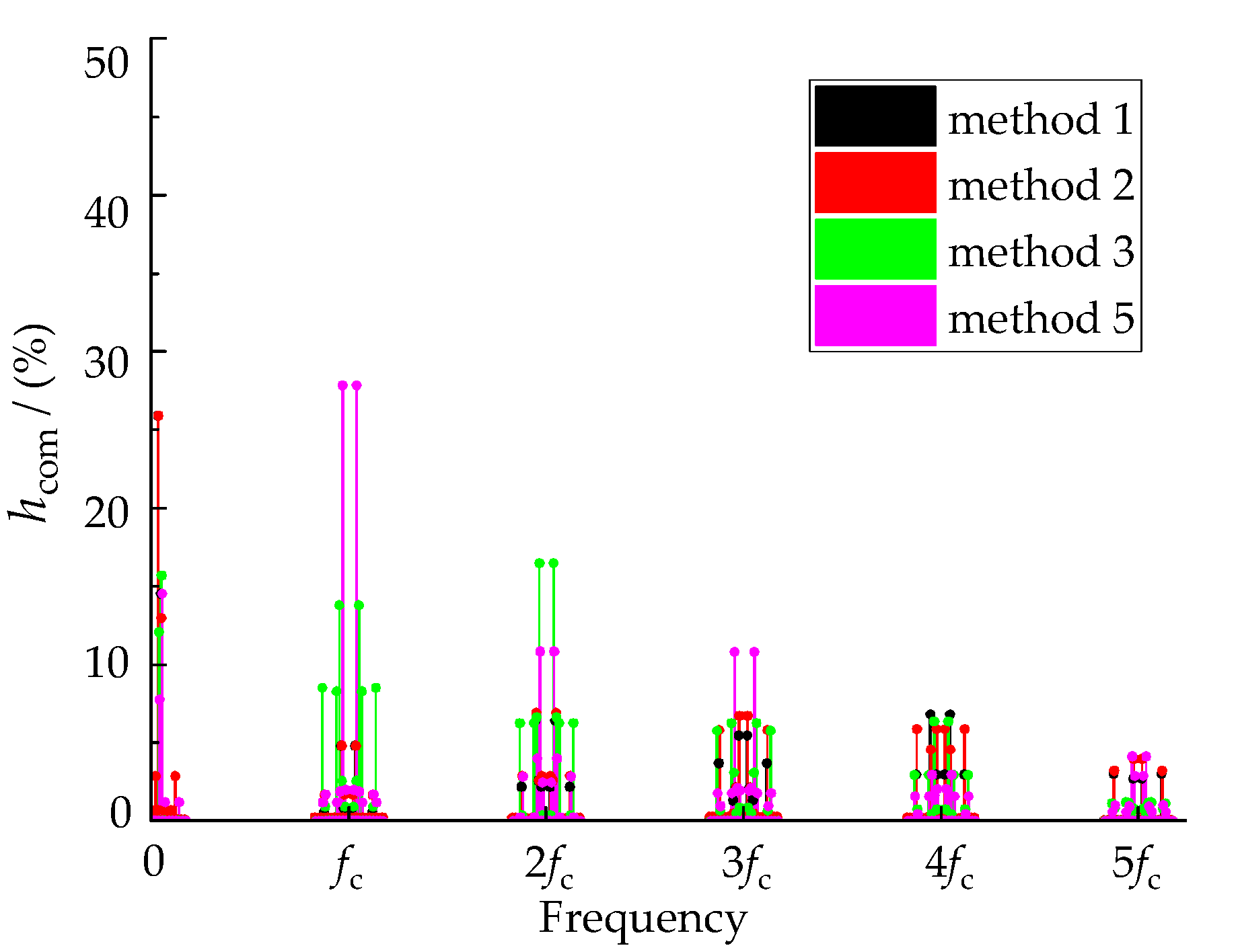
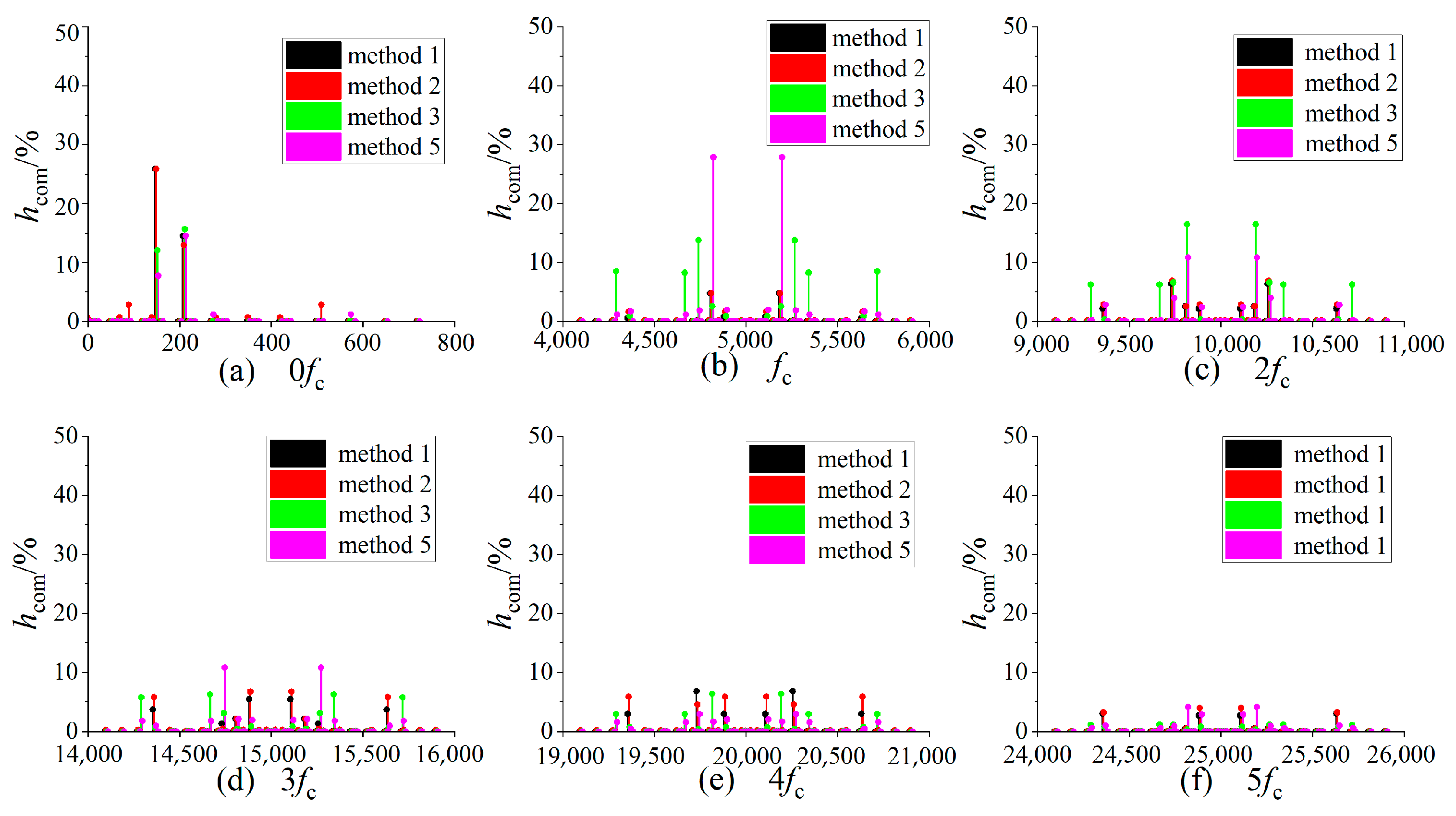


| kin | Current Vectors | Voltage Vectors | Common-Mode Voltage |
|---|---|---|---|
| 1, 3, 5 | Iδ Iγ | V1~V6 | 0.577Vin |
| V7 (111) | Vin | ||
| V0 (000) | 0.866Vin | ||
| 2, 4, 6 | Iδ Iγ | V1~V6 | 0.577Vin |
| V0 (000) | Vin | ||
| V7 (111) | 0.866Vin |
| Method 1 | Method 2 | Method 3 | Method 4 | Method 5 | |
|---|---|---|---|---|---|
| m | 0~0.866 | 0.577~0.866 | 0.577~0.866 | 0~0.500 | 0.667~0.866 |
| kfc ± pfin ± qfout | hcom (%) | |
|---|---|---|
| Method 1 | Method 4 | |
| 3fout | 6.20 | 4.29 |
| 3fin | 25.91 | 18.56 |
| fc ± 3fout | 0.37 | 5.36 |
| fc ± 3fin | 4.88 | 0.43 |
| fc ± 6fin ± 3fout | 5.64 | 1.46 |
| 2fc ± 3fout | 10.21 | 0.18 |
| 2fc ± 3fin | 2.58 | 18.34 |
| 3fc ± 3fout | 0.07 | 2.83 |
| 3fc ± 6fin ± 3fout | 2.96 | 0.95 |
| 4fc ± 3fout | 4.50 | 0.60 |
| 4fc ± 3fin | 0.05 | 5.47 |
| 5fc ± 3fout | 0.18 | 0.78 |
| 5fc ± 6fin ± 3fout | 1.77 | 0.01 |
| kfc ± pfin ± qfout | hcom (%) | |||
|---|---|---|---|---|
| Method 1 | Method 2 | Method 3 | Method 5 | |
| 3fout | 14.54 | 13.35 | 15.70 | 14.50 |
| 3fin | 25.95 | 25.94 | 12.14 | 8.01 |
| fc ± 3fout | 0.14 | 0.17 | 13.72 | 1.30 |
| fc ± 3fin | 4.99 | 4.96 | 0.22 | 27.82 |
| fc ± 6fin ± 3fout | 0.88 | 1.98 | 0.87 | 2.35 |
| 2fc ± 3fout | 5.72 | 6.65 | 8.48 | 4.26 |
| 2fc ± 3fin | 2.64 | 2.65 | 16.95 | 10.98 |
| 3fc ± 3fout | 0.46 | 0.22 | 3.22 | 10.74 |
| 3fc ± 6fin ± 3fout | 4.40 | 6.10 | 0.69 | 1.03 |
| 4fc ± 3fout | 6.61 | 4.82 | 0.65 | 3.25 |
| 4fc ± 3fin | 0.18 | 0.19 | 6.82 | 1.82 |
| 5fc ± 3fout | 0.19 | 0.20 | 1.32 | 1.03 |
| 5fc ± 6fin ± 3fout | 3.05 | 3.12 | 0.85 | 1.39 |
| Parameters | Value |
|---|---|
| Input voltage Vin | 70.7 V |
| Input frequency fin | 50 Hz |
| Input filter parameters Rf-Lf-Cf | 20 Ω/1.7 mH/10 μF |
| Switching frequency fc | 5 kHz |
| Output load R/L | 20 Ω/10 mH |
| Output frequency fout | 70 Hz |
| kfc ± pfin ± qfout | hcom (%) | |
|---|---|---|
| Method 1 | Method 4 | |
| 3fout | 6.01 | 5.83 |
| 3fin | 26.29 | 18.59 |
| fc ± 3fout | 0.68 | 5.09 |
| fc ± 3fin | 5.20 | 0.58 |
| fc ± 6fin ± 3fout | 6.46 | 1.91 |
| 2fc ± 3fout | 10.72 | 0.09 |
| 2fc ± 3fin | 3.03 | 15.43 |
| 3fc ± 3fout | 0.27 | 2.91 |
| 3fc ± 6fin ± 3fout | 2.86 | 1.14 |
| 4fc ± 3fout | 4.88 | 1.38 |
| 4fc ± 3fin | 0.36 | 6.10 |
| 5fc ± 3fout | 0.51 | 0.90 |
| 5fc ± 6fin ± 3fout | 1.42 | 0.17 |
| kfc ± pfin ± qfout | hcom (%) | |||
|---|---|---|---|---|
| Method 1 | Method 2 | Method 3 | Method 5 | |
| 3fout | 13.53 | 13.30 | 13.43 | 11.45 |
| 3fin | 25.72 | 26.03 | 11.96 | 7.92 |
| fc ± 3fout | 0.83 | 0.25 | 12.5 | 1.05 |
| fc ± 3fin | 4.85 | 4.85 | 0.44 | 26.82 |
| fc ± 6fin ± 3fout | 0.85 | 1.68 | 1.26 | 2.15 |
| 2fc ± 3fout | 5.06 | 6.94 | 8.28 | 4.06 |
| 2fc ± 3fin | 2.78 | 2.83 | 17.25 | 10.79 |
| 3fc ± 3fout | 0.89 | 0.62 | 2.92 | 9.98 |
| 3fc ± 6fin ± 3fout | 3.95 | 6.45 | 0.62 | 1.21 |
| 4fc ± 3fout | 6.62 | 5.06 | 0.93 | 3.35 |
| 4fc ± 3fin | 0.35 | 0.33 | 7.38 | 1.16 |
| 5fc ± 3fout | 0.25 | 0.34 | 1.26 | 0.38 |
| 5fc ± 6fin ± 3fout | 2.82 | 3.68 | 0.94 | 1.09 |
Publisher’s Note: MDPI stays neutral with regard to jurisdictional claims in published maps and institutional affiliations. |
© 2022 by the authors. Licensee MDPI, Basel, Switzerland. This article is an open access article distributed under the terms and conditions of the Creative Commons Attribution (CC BY) license (https://creativecommons.org/licenses/by/4.0/).
Share and Cite
Liu, H.; Huang, L.; Lin, C.; Ding, Y.; Wang, Y.; Li, S. Analysis of High-Frequency Common Mode Component Characteristics of Common Mode Peak Voltage Suppression Method for Indirect Matrix Converter. Energies 2022, 15, 3991. https://doi.org/10.3390/en15113991
Liu H, Huang L, Lin C, Ding Y, Wang Y, Li S. Analysis of High-Frequency Common Mode Component Characteristics of Common Mode Peak Voltage Suppression Method for Indirect Matrix Converter. Energies. 2022; 15(11):3991. https://doi.org/10.3390/en15113991
Chicago/Turabian StyleLiu, Haiming, Linfeng Huang, Cheng Lin, Yifu Ding, Yun Wang, and Shanhu Li. 2022. "Analysis of High-Frequency Common Mode Component Characteristics of Common Mode Peak Voltage Suppression Method for Indirect Matrix Converter" Energies 15, no. 11: 3991. https://doi.org/10.3390/en15113991
APA StyleLiu, H., Huang, L., Lin, C., Ding, Y., Wang, Y., & Li, S. (2022). Analysis of High-Frequency Common Mode Component Characteristics of Common Mode Peak Voltage Suppression Method for Indirect Matrix Converter. Energies, 15(11), 3991. https://doi.org/10.3390/en15113991


