Abstract
Pumped storage units improve the stability of the power grid, and the key component is the pump–turbine. A pump–turbine usually needs to start and shutdown frequently, and the operating head varies greatly due to changes in the water level of the reservoir, which makes the dynamic behavior of a pump–turbine runner extremely complex. This paper investigates the effects of operating head on the dynamic response characteristics of a pump–turbine runner in turbine mode. The flow characteristics of the pump–turbine at maximum head, rated head and minimum head are analyzed, and the dynamic response characteristic of the pump–turbine runner are numerically studied. The results show that operating head can affect the pressure pulsation and dynamic stress characteristics of the pump–turbine runner, but it has little effect on the frequency spectra. The conclusions of this paper intend to improve understanding of the effects of the operating head on the dynamic behavior of the pump–turbine runner, therefore providing a theoretical reference for safe and stable operation of the pump–turbine unit.
1. Introduction
Pump–turbines play the role of peak modulation, frequency modulation, phase modulation, energy storage, emergency reserve and black starts in power grids, and they also help improve the safety and stability of the power grid. In recent years, pumped storage stations have been developed rapidly in China [1] to achieve the goal of carbon-neutrality [2]. Pumped storage units are progressing towards higher heads, larger capacities and higher speeds, which brings great challenges to the pump–turbine. Variation of the water level of the reservoir can even reach 30–40 m, so the pump–turbine needs to operate safely within the range of a big head change. Thus, the dynamic behavior of the runner is extremely complex, and it is necessary to study the influence of the head on the dynamic response characteristics of the runner.
The operating pump–turbine runner is affected by the fluid–structure interaction (FSI) [3], i.e., the fluid causes runner deformation, and the deformed runner will in turn affect the flow characteristics. Numerical methods have been widely used to solve FSI problems, and an ideal situation is to solve the fluid-governing equations [4] and the structure-governing equations [5] simultaneously. However, with existing technology, it is difficult to achieve the goal, especially due to the complexity of the Navier–Stokes (N–S) equation. Thus, some researchers have tried to simplify the N–S equation; a widely used method is the acoustic fluid–structural coupling method [6]. He et al. investigated the modal characteristics and the dynamic response characteristics of a pump–turbine runner and discussed the added mass effect in detail [7]. Lais et al. studied the modal characteristics of a Francis turbine runner on the basis of the acoustic fluid–structural coupling method [8], and the numerical method was verified by the experimental results.
In addition, the weak coupling method also provides a way solving FSI problems with fewer computational resources; it can be divided into two types: the one-way coupling method [9] and the two-way coupling method [10]. The two-way coupling method needs the mutual iteration of the calculation results of the fluid field and the structure field [11], and the one-way coupling method ignores the effect of the deformation of the structure on the flow characteristics. The two-way coupling method has been adopted by Pei et al. to study the dynamic stress of a centrifugal pump impeller, and the results show good agreement with the experimental results [12]. However, the two-way coupling method is not as widely used in hydraulic machinery as the one-way coupling method because it still requires more computing resources than the one-way coupling method.
In recent years, the one-way coupling method has been widely used to study the dynamic response characteristics of hydraulic machinery runners [13,14,15]. Zhou et al. studied the effects of operating conditions on the dynamic stress characteristics of a Kaplan turbine runner, and they found that the dynamic stresses in the blade are high when the small guide vane is opening, the blade angle is small and the head is high [16]. Wang et al. studied the dynamic stresses of a piston rod of a Kaplan turbine, and their predicted results agree well with the fracture position [17]. Analysis of the dynamic response characteristics of a medium head Francis turbine runner show that rotor–stator interaction (RSI) might not result in runner damage [18]. However, RSI will greatly increase the dynamic stress as load increases, and becomes the dominant hydraulic phenomenon up to overload of a high head Francis turbine runner [19]. A similar phenomenon was also found in a pump–turbine runner [20]. In addition, a study on the dynamic stress characteristics of a Francis turbine runner show that dynamic stress is one of the main reasons for fatigue and cracking of the blade [21]. Numerical analysis of the dynamic stresses of the pump–turbine runner during start-up show that the mesh density and time step affect the simulation results [22,23]; thus, determination of the appropriate time step and the grid independence check are necessary for the reliability of the numerical results.
According to a literature review, many researchers have studied the dynamic response characteristics of the Francis turbine runner, and the effects of operating conditions on dynamic stress in the blade have been discussed in detail. However, there are few investigations on the dynamic response characteristics of pump–turbine runners, and the complex operating conditions of the pump–turbine require accurate flow calculations to provide force boundary for FSI analysis. In the process of flow calculation, the turbulence model is important for the reliability of the results. The model [24], RNG model and the Shear stress transport (SST) model [25] show good performance for predicting the flow characteristics of hydraulic machinery. Further, the SST model shows good performance for predicting the pressure pulsation characteristics of hydro turbines; thus, it is widely adopted by researchers.
The present work aims to reveal the effect of operating head on the dynamic response characteristics of a pump–turbine runner. The flow characteristics at three typical operating heads: maximum head, rated head and minimum head, are calculated using commercial software Ansys CFX 18.0, and the dynamic response characteristics of the runner at the three operating heads are calculated based on fluid–structure interaction theory. The results of this paper improve the understanding of the effects of operating head on the dynamic behavior of the pump–turbine runner in turbine mode and its safe and stable operation.
2. Pump–Turbine Model and Numerical Method
2.1. The Pump–Turbine Flow Model
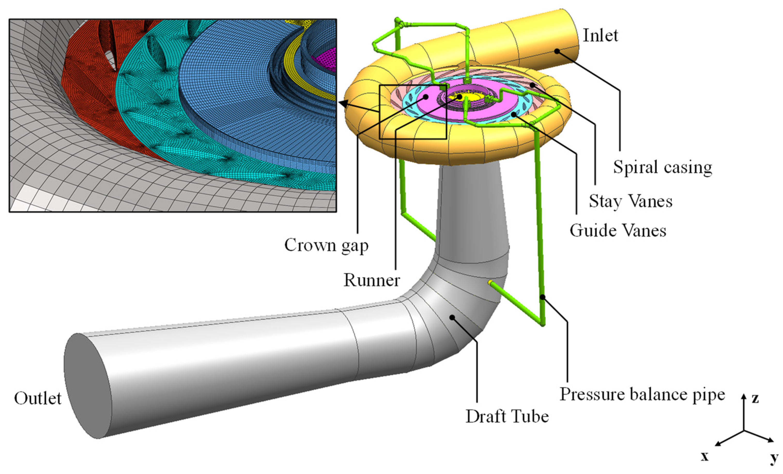
A prototype pump–turbine model was analyzed; it is composed of a spiral casing, two pressure balance pipes, 20 stay vanes, 20 guide vanes, a runner (9 blades) and a draft tube. In addition, the gap between the runner and crown and band was also considered. The fluid domains were meshed by hybrid elements; i.e., hexahedral-type elements were applied to the spiral casing, the stay vanes, guide vanes, crown gap, band gap and pressure balance pipe, while the runner and the draft tube domain adopted hexahedral- and tetrahedral-type elements. Grid-independent analysis is necessary for CFD simulations [26], and the grid-independent analysis has been carried out in the literature [9]. A total of 5,384,011 elements were finally adopted in the fluid domain. The mesh of the CFD domain is shown in Figure 1.

Figure 1.
CFD domain and mesh of pump–turbine.
The design parameters of the pump–turbine as provided by the manufacturer in turbine mode are as follows: runner diameter of 4.16 m, rated head of 430 m (the maximum head is 471.4 m and the minimum head is 412.3 m), rated rotational speed of 428.6 rpm (the rotating direction is +Z), rated flow discharge 79.16 m3/s and rated power of 306.1 MW.
2.2. CFD Simulation Theory and Setup
The flow field of the pump–turbine was solved using commercial software ANSYS CFX on the basis of computational fluid dynamics theory [27], The SST model was adopted as the turbulence model.
The continuity equation and momentum equation are:
where denotes the Reynolds averaged velocity components along the Cartesian coordinate axes, , are the Reynolds stresses for the turbulent flow, is the averaged pressure, is the fluid density, is the kinetic viscosity of the fluid, and are the body forces acting on the unit volume fluid.
The RANS equation with the SST model can be written as:
where is the turbulence scale, is dynamic viscosity, is the production term, is the production term coefficient, is the blending function, and , and are model constants.
The total pressure type inlet was applied to the inlet of the spiral casing, and the draft tube outlet was set as the static pressure outlet. In the three operating heads, the power of the unit was set as 90% of the rated power, and the static pressure at the draft tube outlet was set at the lowest water level of the lower reservoir to compare the results. The runner domain was set as the rotating domain with a rotational speed of 428.6 rpm, and the other domains were set as stationary domains. The interfaces between the rotating domain and the other domains were set as the rotor–stator interface, and the pitch angle was set as 360°. The interfaces between stationary domains were set as general connections. All the solid walls were set with no-slip wall boundary conditions. In the transient simulation, the time step was set as 0.00078 s, i.e., 180 steps in one rotating period. In addition, the numerical results calculated in steady frame were set as the initial values of the transient simulation to improve simulation stability. The fluid medium was set as water at 25 °C, and the convergence criterion root mean square (RMS) was set as 1 × 10⁻⁵.
The pressure pulsations in one flow passage were monitored in ANSYS CFX; the locations of the pressure-monitoring points are shown in Figure 2, wherein monitoring points P1–P4 are located at the suction surface of the blade, and monitoring points P5–P8 are located at the pressure surface of the blade. The dynamic stresses at the same locations were also monitored in the structure analysis software ANSYS Mechanical APDL.
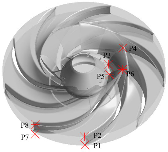
Figure 2.
Pressure pulsation monitoring points and dynamic stress monitoring points.
2.3. Structure Simulation Theory and Setup
The dynamic response characteristics of the runner in the three operating heads were analyzed; the FEM model of the runner is shown in Figure 3 (the mesh was generated using ANSYS mechanical APDL, and the tetrahedral-type Solid185 element was adopted); the connection between the runner and shaft was set as a fixed support.
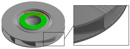
Figure 3.
FEM model and boundary condition of runner.
The FEM model was solved by the linear dynamic equilibrium equation, and the discretized form can be expressed as:
where , and are, respectively, mass matrix, damping matrix and stiffness matrix (n × n matrix, n is the degrees of freedom (DOF)); , and are, respectively, acceleration, velocity and displacement; is the nodal load vector determined by gravitational, centrifugal and hydraulic forces on FSI boundaries.
The material of the runner was set as structural steel (theoretical density of 7850 Kg/m3, Young’s modulus of 2 × 10¹¹ Pa, Poisson’s ratio of 0.3). Gravitational acceleration was set as 9.81 m/s2, and rotational speed was set as 428.6 rpm. The transient pressure loads on the runner surface calculated using ANSYS CFX were applied on the FEM model of the runner to calculate the dynamic response characteristics of the runner.
3. Results and Discussion
3.1. Numerical Method Verification
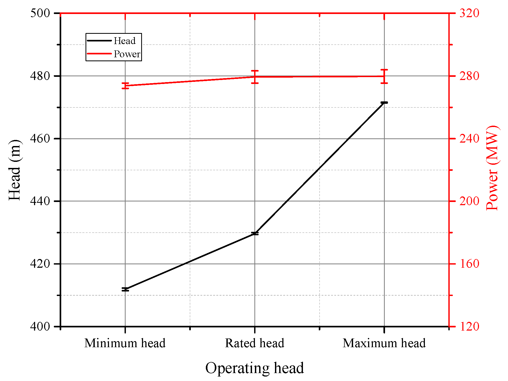
The calculated head and power are compared with the design parameters of the prototype pump–turbine in Figure 4, and numerical error is defined in Equation (6). The line in Figure 4 represents the calculated results, and the error bar represents the error calculated in Equation (6). It can be seen that the numerical results agree well with the design parameters, and the maximum error is less than 1.5%. Thus, the numerical method used in this paper reliably provides the pressure load for the FEM simulation.
where represents the numerical results, and represents the design parameters.
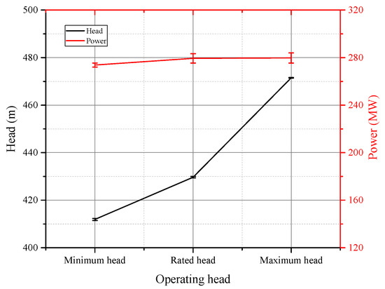
Figure 4.
Validation of the numerical simulation.
3.2. Flow Characteristics of the Pump–Turbine
3.2.1. Basic Flow Characteristics in Flow Passage
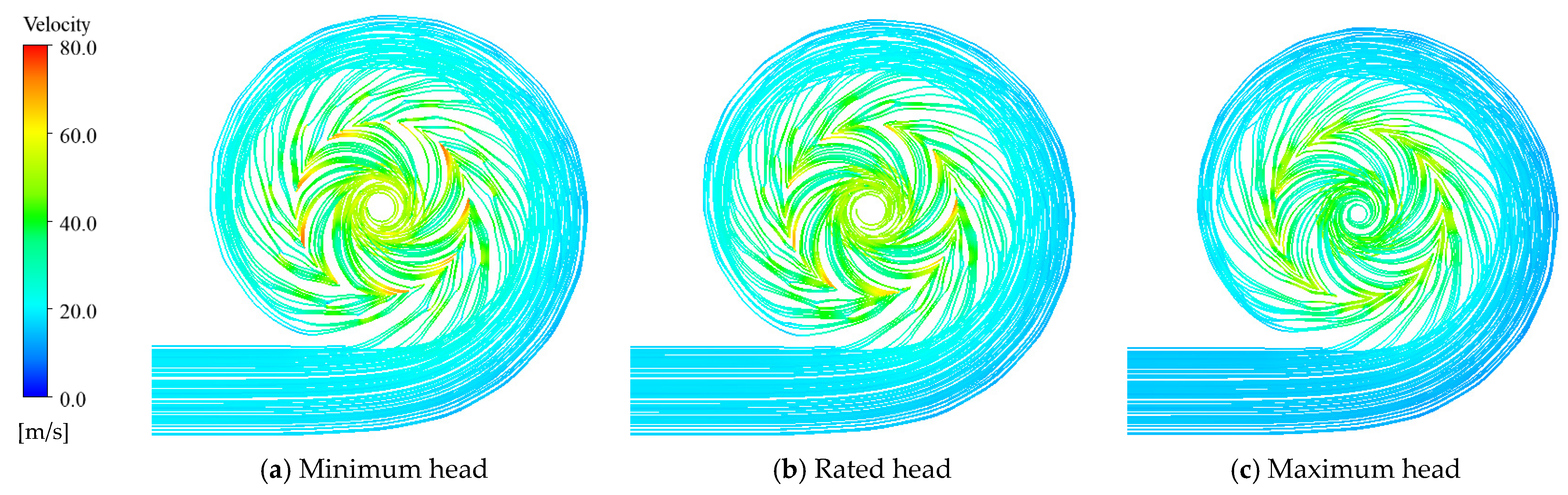
In this section, the streamline in the flow passage and the pressure distribution on the runner surface in steady frame are analyzed first. The streamline in the flow passage is shown in Figure 5. It can be seen that the streamline in the flow passage is similar in different operating heads. The streamline is smooth and the velocity distribution in the flow passage is uniform. In addition, the velocity at the leading edge of the blade is lower at the higher operating head, and the maximum velocity is 80 m/s. This is because the power at the three analyzed operating heads is the same; thus, the guide vane opening is big during low head to obtain large discharge to extract the same amount of power. Discharge at the larger head is smaller; thus, the velocity is lower.
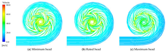
Figure 5.
The streamline in the flow passage in three operating heads.
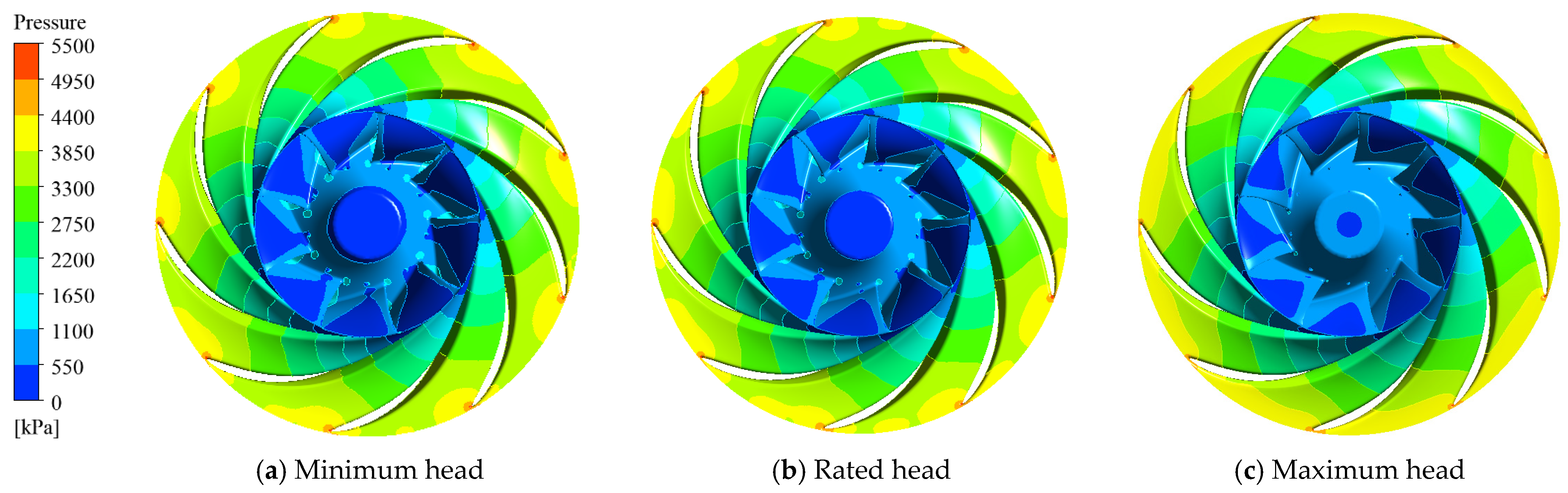
Pressure distribution on the runner’s inner surface is shown in Figure 6. It can be seen that the pressure distribution on the runner’s inner surface shows similar trends; i.e., the pressure distribution on the runner’s inner surface gradually decreases from the leading edge to the trailing edge of the blade, and the low-pressure region is located on the suction surface of the blade. In addition, it can be noted that the maximum pressure is located at the leading edge of the runner blade, and the maximum pressure is about 5500 kPa.
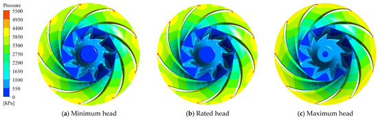
Figure 6.
The pressure distribution on the runner's inner surface in three operating heads.
3.2.2. Pressure Pulsation Characteristics
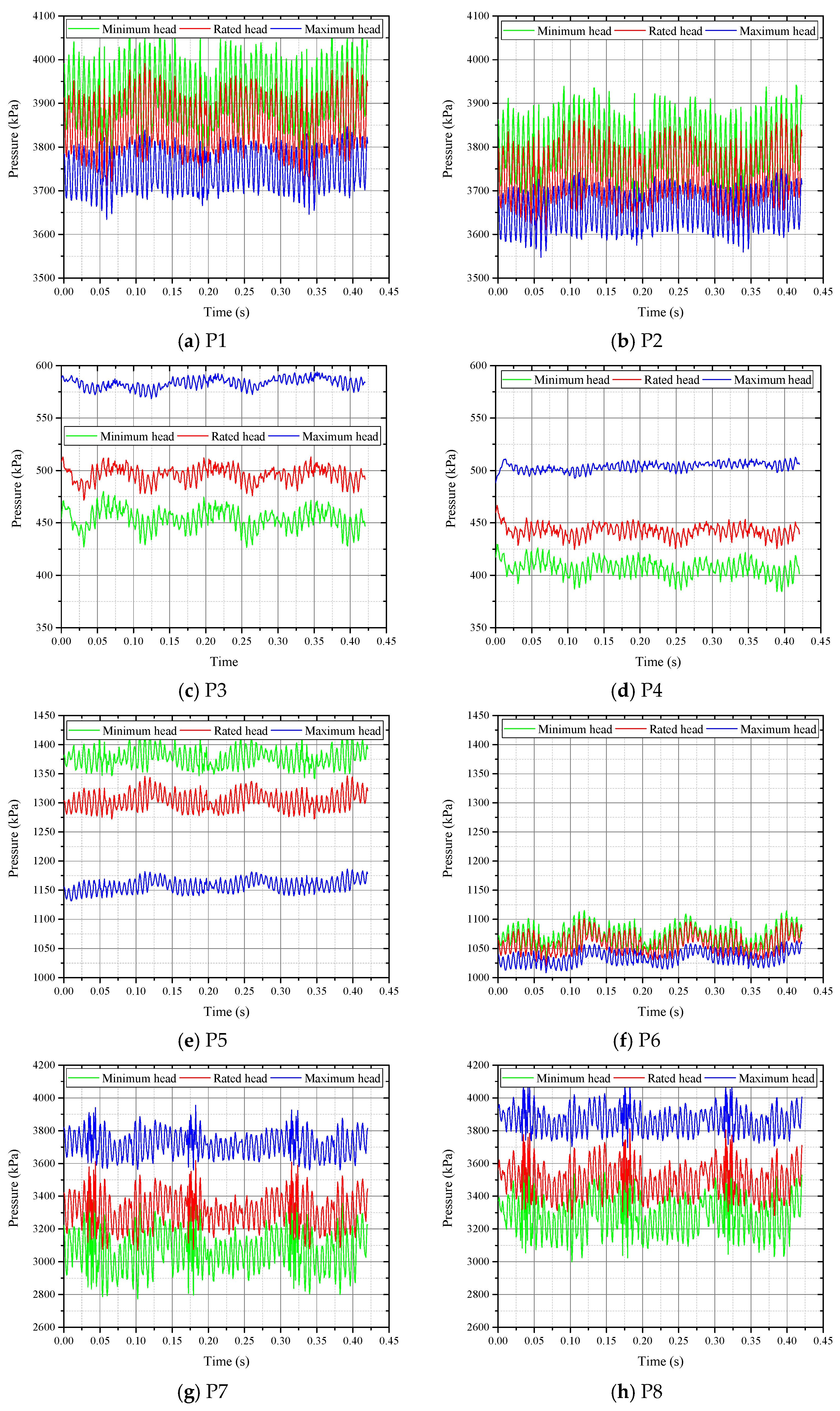
The pressure pulsations at the eight monitoring points are shown in Figure 7. It can be seen that the pressure pulsations show similar trends in the three operating heads. The pressure pulsation at the leading edge of the suction surface (P1, P2) and the trailing edge of the pressure surface (P5, P6) is smaller at the higher head, while the pressure pulsation at the trailing edge of the suction surface (P3, P4) and the leading edge of the pressure surface (P7, P8) is larger at the higher head.
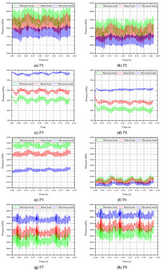
Figure 7.
Pressure pulsation at monitoring points at three analyzed operating heads.
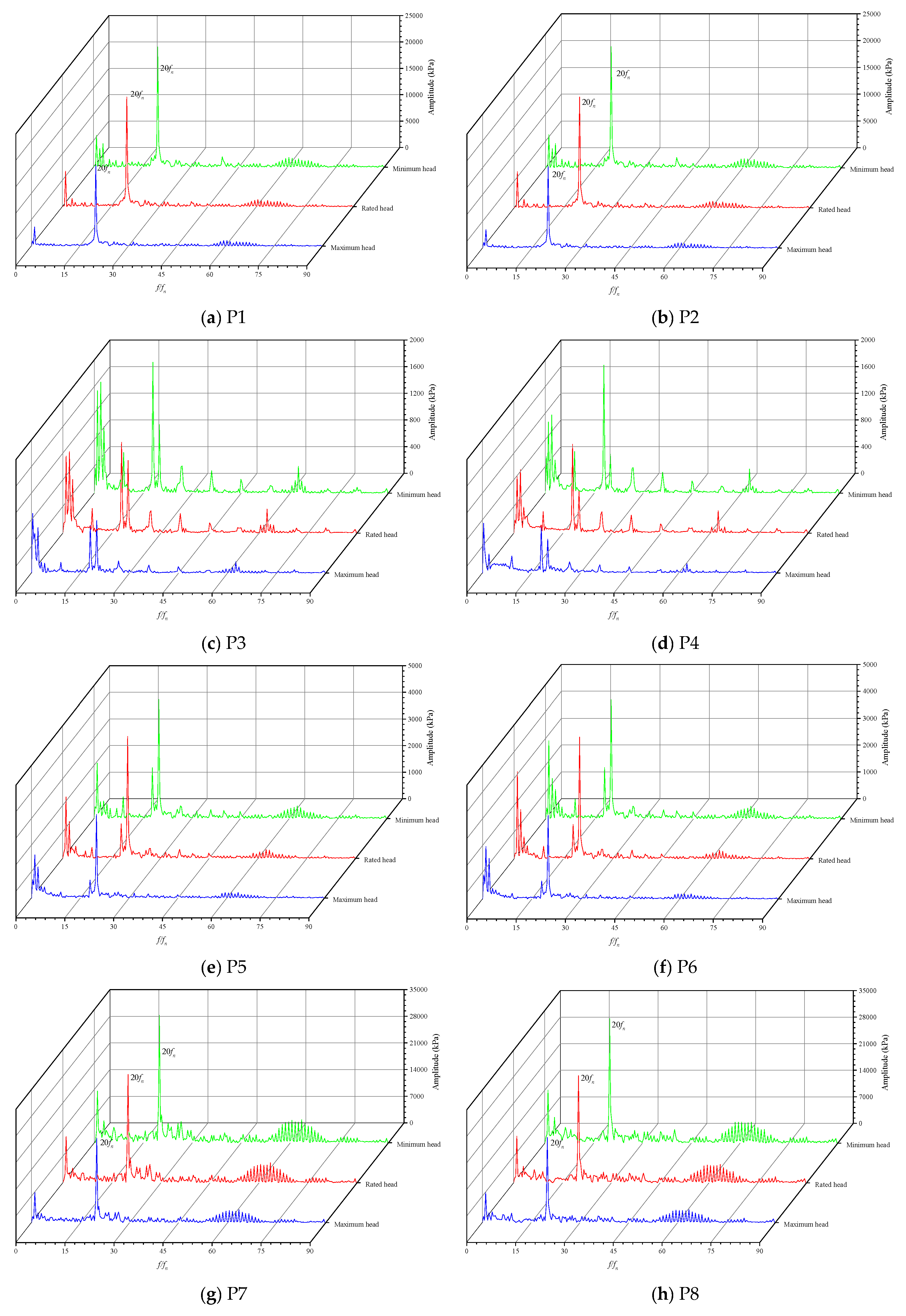
The frequency spectra of the pressure pulsation at the monitoring points are shown in Figure 8, where is the rotational frequency. It can be seen that the rotor–stator interaction (RSI) frequency, i.e., 20, is the dominant frequency of the pressure pulsations at the leading edge of the blade (P1, P2, P7, P8). At the trailing edge of the blade, the frequency spectra of the pressure pulsations become more complex because the trailing edge is close to the draft tube and is more affected by low-frequency components in the vortex rope. Thus, low-frequency components are more obvious in the frequency spectra of the pressure pulsation at P3–P6. In addition, the operating head has little effect on the frequency spectra of the pressure pulsation.
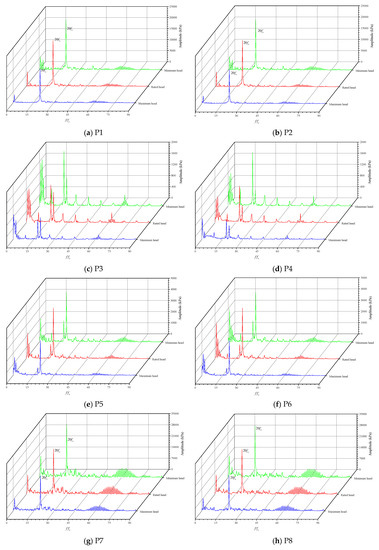
Figure 8.
Frequency spectra of the pressure pulsation at monitoring points.
3.3. Dynamic Response Characteristics of the Runner
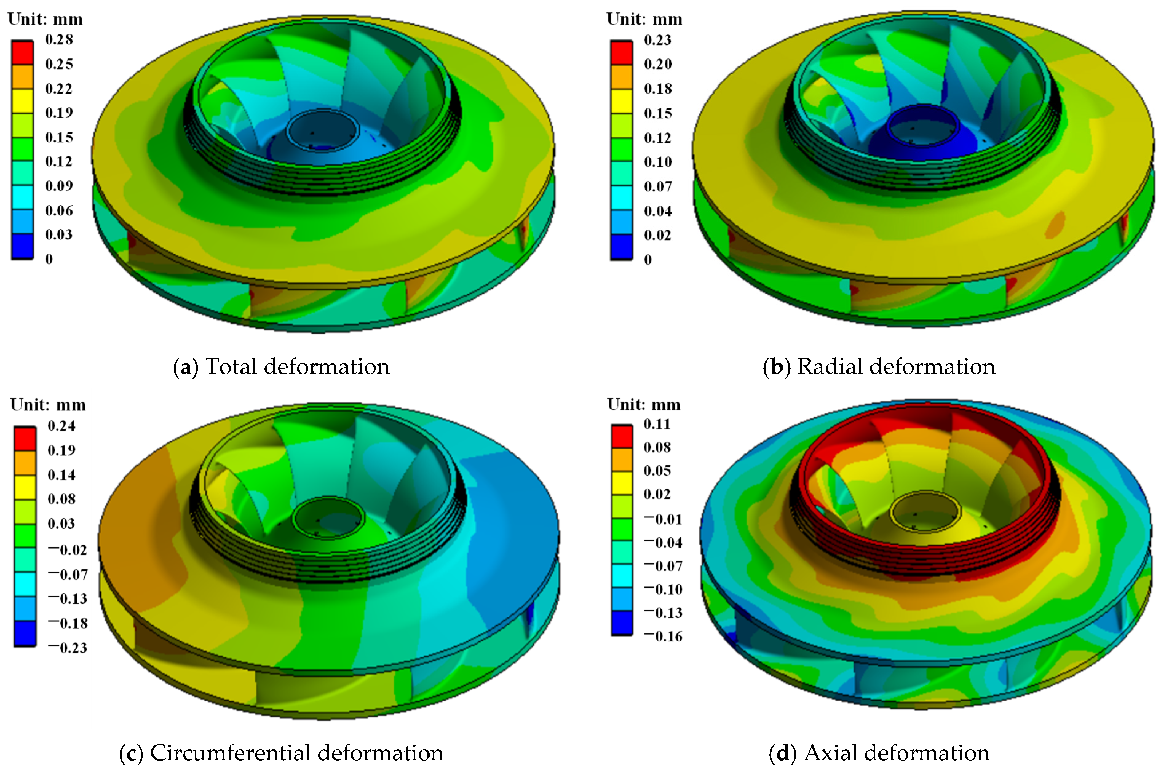
The transient pressure loads calculated in transient conditions using ANSYS CFX were applied to the runner surface, and the time step was set as the same as the fluid simulation. Then, the FEM model in Figure 3 was used to calculate the dynamic response of the runner. Deformation of the runner in rated operating head calculated in steady frame is shown in Figure 9. Both the total deformation and the directional deformation were analyzed in this paper. The total deformation is the vector sum of the radial deformation, axial deformation and circumferential deformation. It can be seen that the deformation shows symmetry; i.e., the deformation in different flow passage is similar. Directional deformation of the runner shows that the maximum radial deformation, maximum circumferential deformation and the maximum axial deformation of the runner are 0.23 mm, 0.24 mm and −0.16 mm (the negative value represents downward deformation), respectively. The maximum total deformation of the runner is about 0.28 mm. The axial deformation of the runner shows that the lower section of the band deforms upward, but the outer radius of the runner deforms downward. This is because the pressure distribution on the runner gradually decreases from the outer radius to the inner radius.
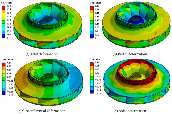
Figure 9.
Total and directional deformations of the runner in rated operating condition.
The von Mises stress on the runner in the rated operating condition is shown in Figure 10. Similar to the deformation of the runner, the von Mises stress on the runner also shows symmetry. The maximum von Mises stress is about 121.4 MPa.
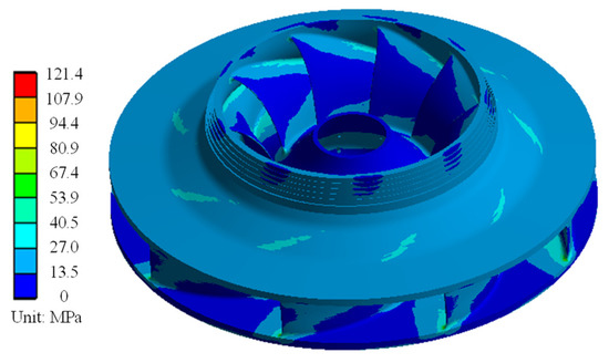
Figure 10.
Von-Mises stress on the runner in rated operating condition.
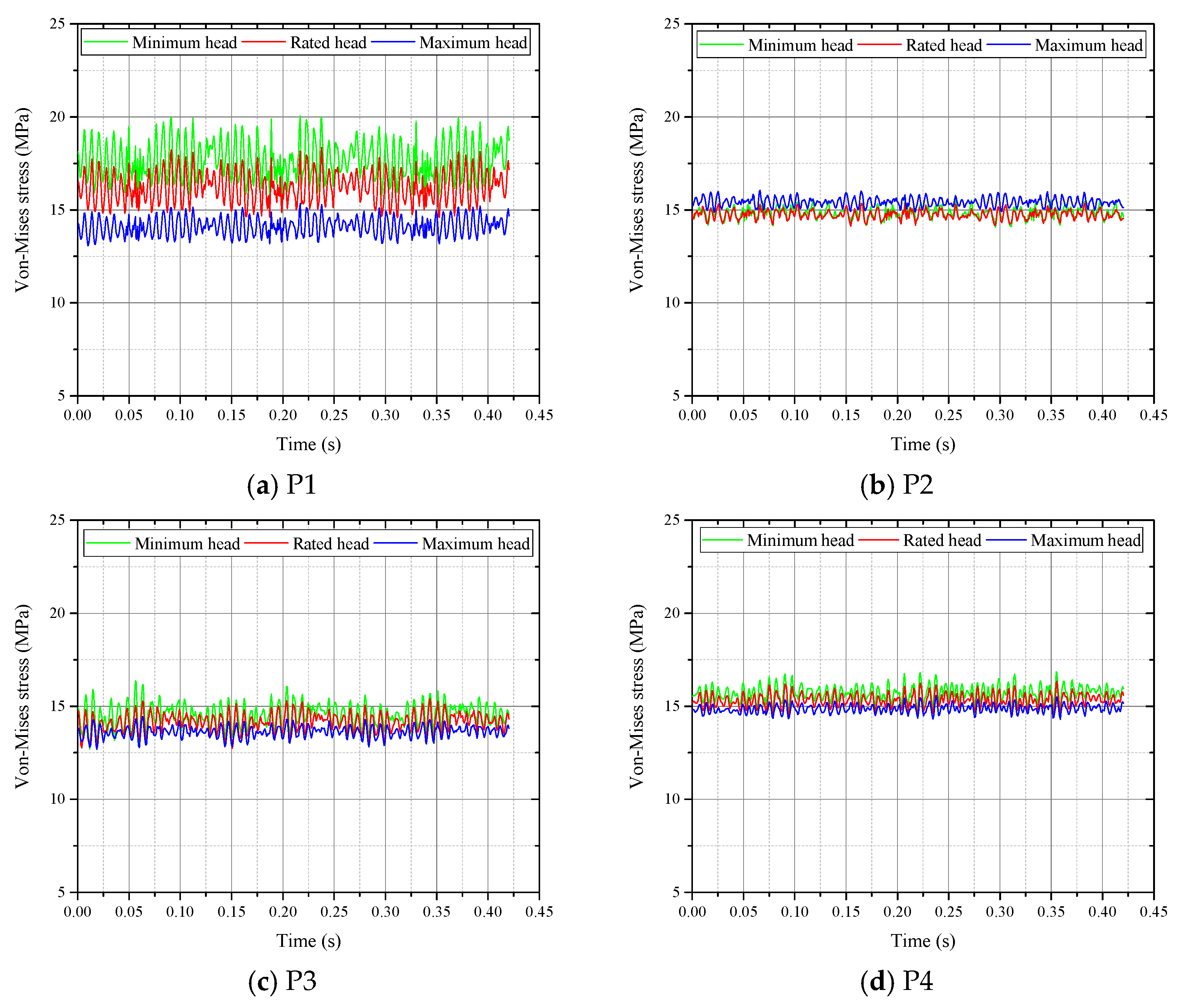
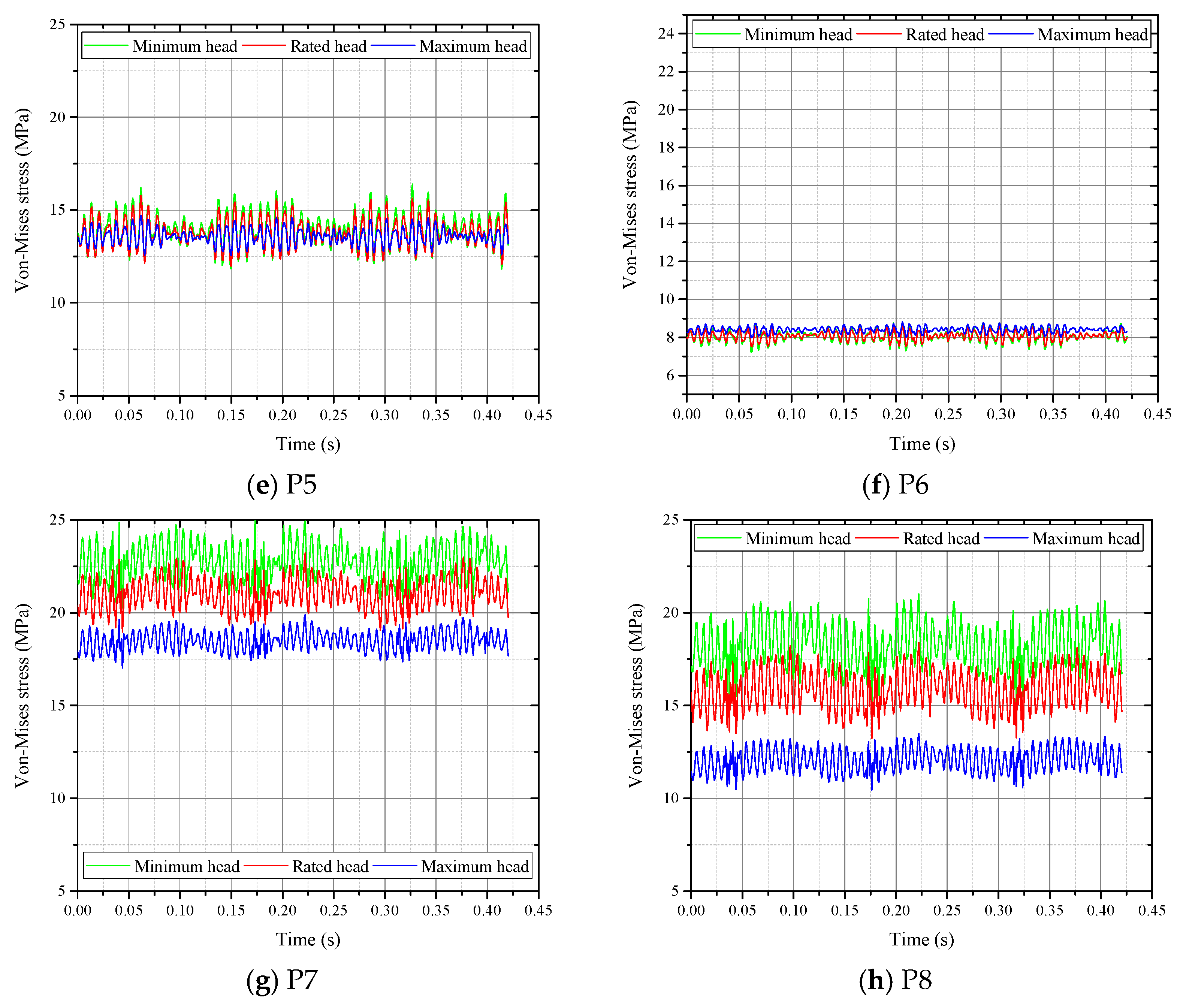
The dynamic stresses at the monitoring points are shown in Figure 11. It can be seen that the dynamic stress at the monitoring points is less than 25 MPa. The relationship between dynamic stress and operating head depends on location: the dynamic stresses at P2 and P6 increase with increasing operating head, while the opposite is true for the remaining monitoring points, which is different from the relationship between pressure pulsation and operating head. This is because the dynamic stress at one point of the FEM model is the result of the comprehensive effect of the nearby pressure; the dynamic stress and the pressure pulsation at the same point might show different trends.

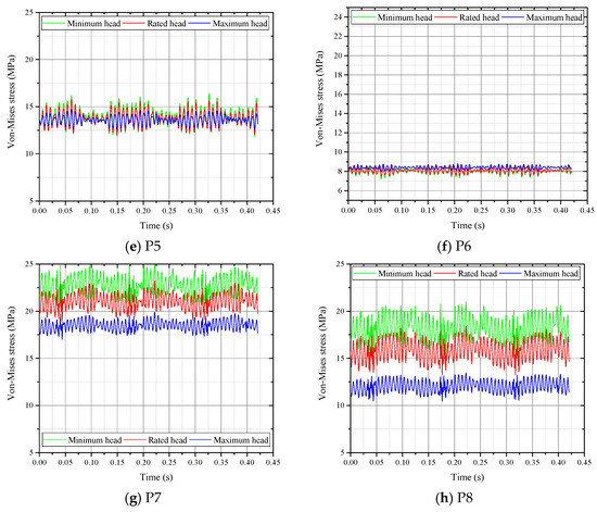
Figure 11.
Dynamic stresses at monitoring points.
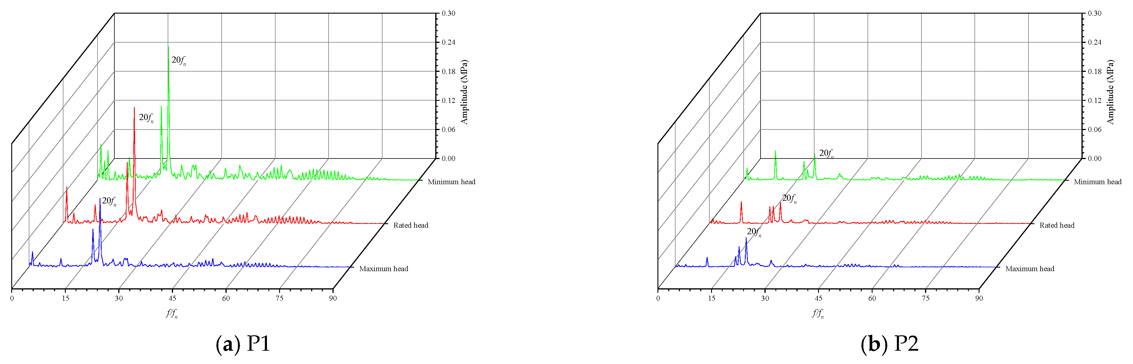
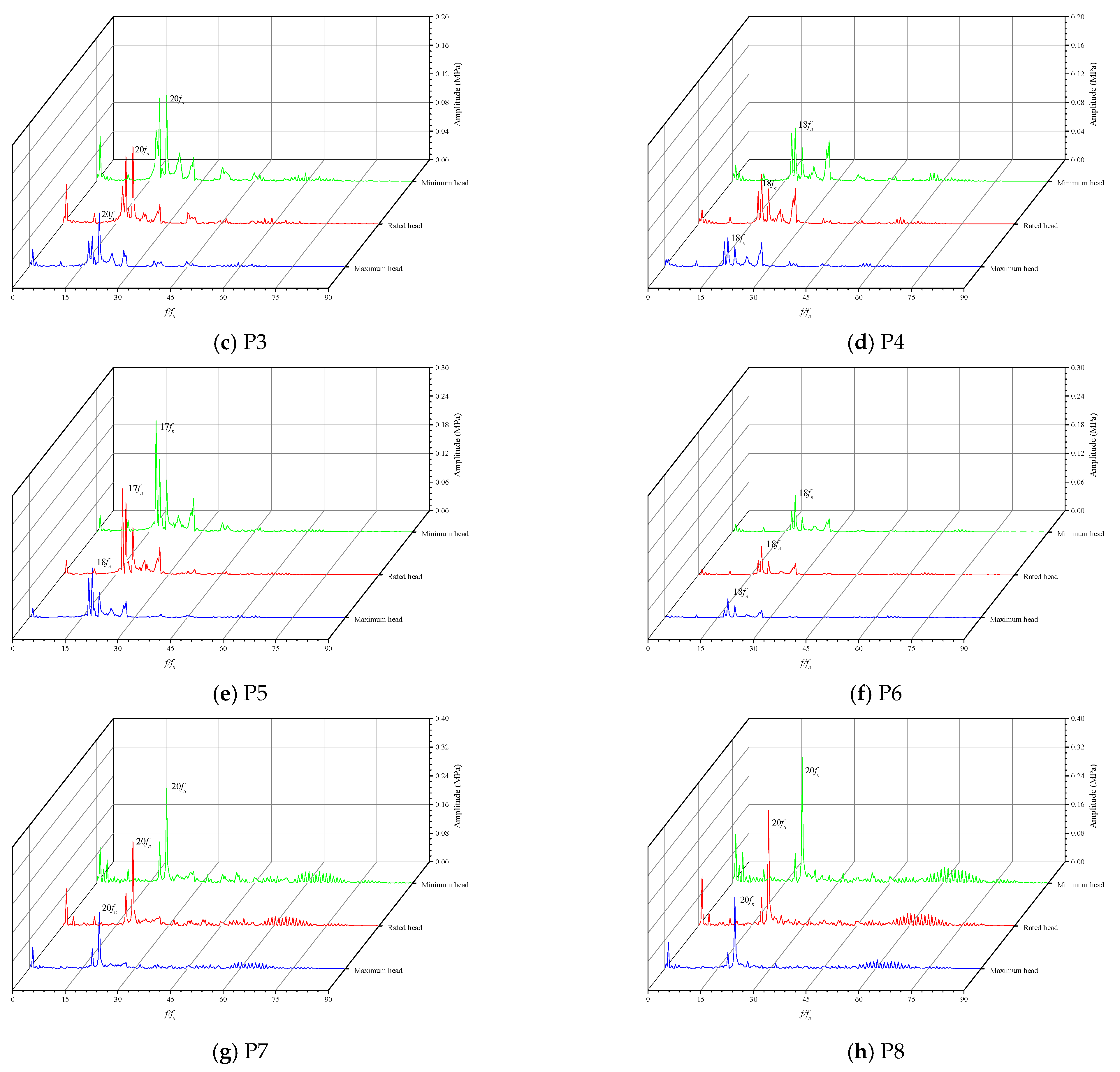
The frequency spectra of the dynamic stresses at the monitoring points are shown in Figure 12. It can be seen that the frequency spectra of the dynamic stresses are different at different monitoring points. The RSI frequency is the dominant frequency of the dynamic stress at the leading edge of the blade (P1, P2, P7, P8). At the trailing edge of the blade, the dominant frequency of the dynamic stress is not the RSI frequency, this is because of the frequency spectra of the pressure pulsation. The operating head has little effect on the frequency spectra of the dynamic stress; only the dominant frequency of the dynamic stress at P5 changes from 17 at minimum head and rated head to 18 at maximum head.
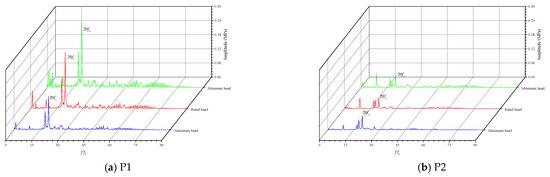
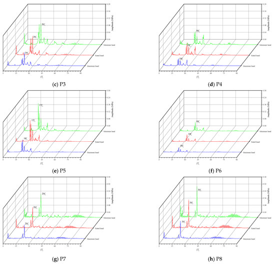
Figure 12.
Frequency spectra of the dynamic stress at monitoring points.
3.4. Discussion
The present work investigates effects of operating head on the dynamic response characteristics of a pump–turbine runner in turbine mode using the weak fluid–structure coupling method (i.e., the effects of deformation of the runner on flow characteristics of the pump–turbine are small, so we only consider the effects of flow characteristics on the dynamic response of the runner). This method has been widely adopted in the literature, and its reliability on pump–turbine models has been verified [8,19,20,28,29]. The two-way coupling method is closer to the real condition, but it requires very high computing resources. Thus, it is necessary to choose between computing resource and computing speed in engineering.
Calculation of flow characteristics provides a pressure boundary condition for dynamic response analysis of runners. Therefore, accuracy of the CFD results is significant for accuracy of the dynamic response results. Some factors, such as mesh density, mesh type, time step, turbulence model, etc., have been proven to affect CFD results. Thus, reasonable selection of the numerical model is important for the CFD results, and the effect of the above factors could be analyzed in detail in future work.
In engineering, the operating conditions of pump–turbines are quite complex. Pump–turbines need to frequently start and shutdown and usually operates in part-load conditions. In addition, the water level of the upper reservoir and the lower reservoir keeps changing; thus, the operating head of the pump–turbine dynamically changes. This paper investigates the effects of three typical operating heads on the dynamic response characteristics of the pump–turbine runner, but dynamic variation of the operating head is not considered. Therefore, it is interesting and necessary to study the effects of dynamic variation of the water level on the dynamic response characteristics of the runner in typical stable (full-load and part-load) and transient (start-up, shutdown, etc.) operating conditions in turbine mode and pump mode.
4. Conclusions
This paper investigated the effects of the operating head on the dynamic response characteristics of a prototype pump–turbine runner; the selected operating conditions were three typical operating conditions: maximum head, rated head and minimum head. The power in the three operating conditions was 90% of the rated power. Transient flow characteristics were obtained first, and then transient pressure loads on the runner surface were applied on the FEM model of the runner to calculate the dynamic response characteristics of the runner. The main conclusions in this paper are as follows:
- (1)
- The calculated flow characteristics show good agreement with the design parameters, and the maximum numerical error is less than 1.5%.
- (2)
- The pressure distribution on the runner’s inner surface, the deformation on the runner, as well as the stress distribution on the runner show symmetry. The maximum total deformation of the runner is 0.28 mm, which is mainly due to radial deformation and circumferential deformation. Axial deformation of the runner shows that the outer radius of the runner deforms downward, but the lower section of the band deforms upward due to distribution of the pressure. However, deformation of the runner is dependent on operating conditions, and more in-depth studies are needed. In addition, the maximum von Mises stress on the runner is 121.4 MPa.
- (3)
- The pressure pulsation at the leading edge of the suction surface and the trailing edge of the pressure surface is smaller at higher head, while the pressure at the trailing edge of the suction surface and the leading edge of the pressure surface is larger at higher head. The operating head has little effect on the frequency spectra of the pressure pulsation. The dominant frequency of the frequency spectra of the pressure pulsations at the leading edge of the blade is the RSI frequency, while low-frequency components are more obvious at the frequency spectra of the pressure pulsations at the trailing edge of the blade.
- (4)
- The dynamic stresses at the monitoring points are less than 25 MPa, and the dynamic stress might be smaller at the higher operating head. The operating head has little effect on the frequency spectra of the dynamic stress.
Overall, this paper reveals the effects of the operating head on the pressure pulsation and dynamic stresses of a pump–turbine runner; the results are helpful for safe and stable operation of the pump–turbine unit.
Author Contributions
Data curation, writing—original draft, X.L.; investigation, J.C.; formal analysis, J.Z.; methodology, T.W.; project administration, H.Z.; software, Y.W.; validation, W.Z. and G.L.; conceptualization, funding acquisition, writing—review and editing, Z.W. All authors have read and agreed to the published version of the manuscript.
Funding
This research was funded by Science and Technology Project of State Grid Corporation of China.
Institutional Review Board Statement
Not applicable.
Informed Consent Statement
Not applicable.
Data Availability Statement
Not applicable.
Conflicts of Interest
The authors declare no conflict of interest.
References
- National Energy Administration. Medium and Long Term Development Planning of Pumped Storage (2021–2035); National Energy Administration: Beijing, China, 2021. [Google Scholar]
- Jia, Z.; Lin, B. How to achieve the first step of the carbon-neutrality 2060 target in China: The coal substitution perspective. Energy 2021, 233, 121179. [Google Scholar] [CrossRef]
- Trivedi, C. A review on fluid structure interaction in hydraulic turbines: A focus on hydrodynamic damping. Eng. Fail. Anal. 2017, 77, 1–22. [Google Scholar] [CrossRef]
- Terentiev, L. The Turbulence Closure Model Based on Linear Anisotropy Invariant Analysis; Friedrich-Alexander University: Erlangen-Nuremberg, Germany, 2006. [Google Scholar]
- Cao, J.; Tian, H.; Ahn, S.-H.; Duo, W.; Bi, H.; Zhao, L.; Zhao, G.; Gao, H.; Wang, M.; Ma, G.; et al. Fatigue analysis in rotor of a prototype bulb turbine based on fluid-structure interaction. Eng. Fail. Anal. 2021, 132, 105940. [Google Scholar] [CrossRef]
- Cao, J.; Luo, Y.; Presas, A.; Ahn, S.-H.; Wang, Z.; Huang, X.; Liu, Y. Influence of rotation on the modal characteristics of a bulb turbine unit rotor. Renew. Energy 2022, 187, 887–895. [Google Scholar] [CrossRef]
- He, L.; Zhou, L.; Ahn, S.-H.; Wang, Z.; Nakahara, Y.; Kurosawa, S. Evaluation of gap influence on the dynamic response behavior of pump-turbine runner. Eng. Comput. 2019, 36, 491–508. [Google Scholar] [CrossRef]
- Lais, S.; Liang, Q.; Henggeler, U.; Weiss, T.; Escaler, X.; Egusquiza, E. Dynamic Analysis of Francis Runners—Experiment and Numerical Simulation. Int. J. Fluid Mach. Syst. 2009, 2, 303–314. [Google Scholar] [CrossRef] [Green Version]
- Kong, L.; Cao, J.; Li, X.; Zhou, X.; Hu, H.; Wang, T.; Gui, S.; Lai, W.; Zhu, Z.; Wang, Z.; et al. Numerical Analysis on the Hydraulic Thrust and Dynamic Response Characteristics of a Turbine Pump. Energies 2022, 15, 1580. [Google Scholar] [CrossRef]
- Kan, K.; Zheng, Y.; Fu, S.; Liu, H.; Yang, C.; Zhang, X. Dynamic stress of impeller blade of shaft extension tubular pump device based on bidirectional fluid-structure interaction. J. Mech. Sci. Technol. 2017, 31, 1561–1568. [Google Scholar] [CrossRef]
- Dompierre, F.; Sabourin, M. Determination of turbine runner dynamic behaviour under operating condition by a two-way staggered fluid-structure interaction method. IOP Conf. Ser. Earth Environ. Sci. 2010, 12, 012085. [Google Scholar] [CrossRef]
- Pei, J.; Yuan, S.; Yuan, J. Dynamic stress analysis of sewage centrifugal pump impeller based on two-way coupling method. Chin. J. Mech. Eng. 2014, 27, 369–375. [Google Scholar] [CrossRef]
- Saeed, R.A.; Galybin, A.N.; Popov, V. 3D fluid–structure modelling and vibration analysis for fault diagnosis of Francis turbine using multiple ANN and multiple ANFIS. Mech. Syst. Signal Process. 2013, 34, 259–276. [Google Scholar] [CrossRef]
- Saeed, R.A.; Galybin, A.N.; Popov, V. Modelling of flow-induced stresses in a Francis turbine runner. Adv. Eng. Softw. 2010, 41, 1245–1255. [Google Scholar] [CrossRef]
- Franco-Nava, J.M.; Dorantes-Gómez, O.; Rosado-Tamariz, E.; Fernández-Dávila, J.M.; Rangel-Espinosa, R. Flow Induced Stresses in a Francis Turbine Runner Using Computer-Based Design Tools. In Proceedings of the ASME 2009 Fluids Engineering Division Summer Meeting, Vail, CO, USA, 2–6 August 2009. [Google Scholar]
- Zhou, L.; Wang, Z.; Xiao, R.; Luo, Y. Analysis of dynamic stresses in Kaplan turbine blades. Eng. Comput. 2007, 24, 753–762. [Google Scholar] [CrossRef]
- Wang, Z.W.; Luo, Y.Y.; Zhou, L.J.; Xiao, R.F.; Peng, G.J. Computation of dynamic stresses in piston rods caused by unsteady hydraulic loads. Eng. Fail. Anal. 2008, 15, 28–37. [Google Scholar] [CrossRef]
- Guillaume, R.; Deniau, J.L.; Scolaro, D.; Colombet, C. Influence of the rotor-stator interaction on the dynamic stresses of Francis runners. IOP Conf. Ser. Earth Environ. Sci. 2012, 15, 052011. [Google Scholar] [CrossRef]
- Huang, X.; Oram, C.; Sick, M. Static and dynamic stress analyses of the prototype high head Francis runner based on site measurement. IOP Conf. Ser. Earth Environ. Sci. 2014, 22, 032052. [Google Scholar] [CrossRef] [Green Version]
- Chen, F.; Bi, H.; Ahn, S.-H.; Mao, Z.; Luo, Y.; Wang, Z. Investigation on Dynamic Stresses of Pump-Turbine Runner during Start Up in Turbine Mode. Processes 2021, 9, 499. [Google Scholar] [CrossRef]
- Xiao, R.; Wang, Z.; Luo, Y. Dynamic Stresses in a Francis Turbine Runner Based on Fluid-Structure Interaction Analysis. Tsinghua Sci. Technol. 2008, 13, 587–592. [Google Scholar] [CrossRef]
- Morissette, J.F.; Nicolle, J. Fluid-structure simulations of the stochastic behaviour of a medium head Francis turbine during startup. IOP Conf. Ser. Earth Environ. Sci. 2019, 240, 022026. [Google Scholar] [CrossRef]
- Melot, M.; Coulaud, M.; Chamberland-Lauzon, J.; Nennemann, B.; Deschênes, C. Hydraulic turbine start-up: A fluid-structure simulation methodology. IOP Conf. Ser. Earth Environ. Sci. 2019, 240, 022024. [Google Scholar] [CrossRef]
- Liu, S.; Li, S.; Wu, Y. Pressure Fluctuation Prediction of a Model Kaplan Turbine by Unsteady Turbulent Flow Simulation. J. Fluids Eng. 2009, 131, 101102. [Google Scholar] [CrossRef]
- Zhao, X.; Xiao, Y.; Wang, Z.; Luo, Y.; Cao, L. Unsteady Flow and Pressure Pulsation Characteristics Analysis of Rotating Stall in Centrifugal Pumps Under Off-Design Conditions. J. Fluids Eng. 2018, 140, 021105. [Google Scholar] [CrossRef] [Green Version]
- Fu, X.; Li, D.; Wang, H.; Zhang, G.; Li, Z.; Wei, X. Numerical simulation of the transient flow in a pump-turbine during load rejection process with special emphasis on hydraulic acoustic effect. Renew. Energy 2020, 155, 1127–1138. [Google Scholar] [CrossRef]
- Ferziger, J.H.; Perić, M.; Street, R.L. Computational Methods for Fluid Dynamics, 4th ed.; Springer Nature Switzerland AG: Cham, Switzerland, 2020. [Google Scholar]
- Luo, Y.; Wang, Z.; Zhou, L.; Peng, G.; Sun, G. Computation of Static and Dynamic Stresses of a Bulb Tubular Turbine. In Proceedings of the 2008 ASME Fluids Engineering Conference, Jacksonville, FL, USA, 10–14 August 2008. [Google Scholar]
- Trivedi, C.; Cervantes, M.J. Fluid-structure interactions in Francis turbines: A perspective review. Renew. Sustain. Energy Rev. 2017, 68, 87–101. [Google Scholar] [CrossRef]


Publisher’s Note: MDPI stays neutral with regard to jurisdictional claims in published maps and institutional affiliations. |
© 2022 by the authors. Licensee MDPI, Basel, Switzerland. This article is an open access article distributed under the terms and conditions of the Creative Commons Attribution (CC BY) license (https://creativecommons.org/licenses/by/4.0/).