Article

Study on the Positioning Accuracy of the GNSS/INS System Supported by the RTK Receiver for Railway Measurements

1
Department of Transport and Logistics, Gdynia Maritime University, Morska 81-87, 81-225 Gdynia, Poland
2
Department of Geodesy and Oceanography, Gdynia Maritime University, Morska 81-87, 81-225 Gdynia, Poland
3
Department of Geodesy, Gdańsk University of Technology, Gabriela Narutowicza 11-12, 80-233 Gdańsk, Poland
*
Author to whom correspondence should be addressed.
Energies 2022, 15(11), 4094; https://doi.org/10.3390/en15114094
Submission received: 25 April 2022 / Revised: 26 May 2022 / Accepted: 30 May 2022 / Published: 2 June 2022
(This article belongs to the Special Issue Advanced Technologies in New Energy Vehicle)

Abstract

:
Currently, the primary method for determining the object coordinates is positioning using Global Navigation Satellite Systems (GNSS) supported by Inertial Navigation Systems (INS). The main goal of this solution is to ensure high positioning availability, particularly when access to satellite signals is limited (in tunnels, areas with densely concentrated buildings and in forest areas). The aim of this article is to determine whether the GNSS/INS system supported by the RTK receiver is suitable for the implementation of selected geodetic and construction tasks in railway engineering, such as determining the place and extent of rail track deformations (1 cm (p = 0.95)), the process of a rapid stocktaking of existing rail tracks (3 cm (p = 0.95)) and for design and construction works (10 cm (p = 0.95)), as well as what the impact of various terrain obstacles have on the obtained positioning accuracy of the tested system. During the research, one INS was used, the Ekinox2-U by the SBG Systems, which was supported by the Real-Time Kinematic (RTK) receiver. GNSS/INS measurements were conducted on three representative sections varying in terms of terrain obstacles that limit the access to satellite signals during mobile railway measurements in Tricity (Poland). The acquired data allowed us to calculate the basic position accuracy measures that are commonly used in navigation and transport applications. On this basis, it was concluded that the Ekinox2-U system can satisfy the positioning accuracy requirements for rapid stocktaking of existing rail tracks (3 cm (p = 0.95)), as well as for design and construction works (10 cm (p = 0.95)). On the other hand, the system cannot be used to determine the place and extent of rail track deformations (1 cm (p = 0.95)).

1. Introduction

Mobile Global Navigation Satellite System (GNSS) measurements in railway engineering were initiated by Cezary Specht and Władysław Koc in 2009 [1] during an inventory of a railway route on a section between Kościerzyna and Kartuzy (Poland) [2]. The study used four GNSS geodetic receivers and Aktywna Sieć Geodezyjna EUPOS (ASG-EUPOS), a newly-established GNSS geodetic network (the first in Poland). The results of this campaign confirmed the high applicability of this measurement method and showed the limitations of the GNSS signal availability in built-up areas. During subsequent studies, a continuous increase was noted in terms of the accuracy and availability of mobile satellite measurements, resulting primarily from the improvement in operational and technical characteristics of the two main GNSS systems (Global Positioning System (GPS) and GLObal NAvigation Satellite System (GLONASS)), the construction of other GNSS systems (BeiDou Navigation Satellite System (BDS) and Galileo), the development of new methods for generating correction data (Real Time Network (RTN)) and the establishment of new GNSS geodetic networks in Poland (SmartNet, TPI NETpro and VRSNet.pl). Starting from the first measurement campaign, the study was conducted in two main directions, i.e., geodetic, which involved increasing the positioning accuracy and availability of mobile GNSS measurements, as well as design, which aimed at developing new design and operational methods [3]. The research was culminated by the implementation of a research project entitled “Development of an innovative method for determining the precise trajectory of a railway vehicle” (InnoSatTrack) in the years 2018–2021. The aim of this project was to develop an innovative method for determining the rail track axis trajectory using mobile photogrammetric methods, GNSS, Inertial Navigation System (INS) and 3D laser scanning [4,5,6]. The obtained results will be used to more efficiently reproduce the coordinates of the existing rail track infrastructure [7,8,9]. Another purpose of the study was to develop methods for more accurate positioning/locating railway vehicles in real-time (the position and velocity) using GNSS/INS systems [3]. The final aim of the project was to develop a data acquisition and processing system from all measurement systems [10]. The system was implemented into an online application based on the most recent technology for handling the following layers: business, database access and presentation.
Worldwide research results indicate that an increase in the number of measurement systems and their variability in terms of methods leads to an improvement in the precision of determining the course of a rail route, as well as its modelling [11,12,13,14,15]. In order to determine this clearly, in the years 2009–2021, the authors of this article assessed the availability of three accuracy levels: deformation (1 cm (p = 0.95)), stocktaking (3 cm (p = 0.95)) and design (10 cm (p = 0.95)), that were required to perform various construction and geodetic tasks in railway engineering [16]. Since the individual tasks realized in railway engineering have different positioning accuracy requirements, it is important to know which GNSS/INS system is suitable for what task. Hence, it was decided to determine the usefulness of the GNSS/INS system supported by the Real-Time Kinematic (RTK) receiver for railway measurements.
For several years now, GNSS/INS systems have been increasingly used in railway applications. Chen et al. [17] used these systems to study the railway track irregularity for high-speed lines. This made it possible to identify the railway track irregularity with a relative accuracy of 1 mm. Similar tests and results were carried out by Li et al. [18], during which they obtained that the accuracy of the deformation monitoring is 1 mm in the horizontal plane and 1.5 mm in the vertical plane. Other studies were conducted by Zhang et al. [19]. On their basis, they observed that the accuracy of the railway track irregularity is 0.67 mm (Root Mean Square (RMS)) and 0.16 mm (relative error). Zhou et al. [15] performed kinematic measurements of the railway track centerline position using multisensor data fusion from GNSS, INS and an odometer. Research has shown that errors do not exceed 0.6 cm in the horizontal plane and 1.1 cm in the vertical plane. Data fusion from different sensors is also used by other authors. Thanks to the data from GNSS, INS and an odometer, Zhang et al. [20] were able to determine the geometrical parameters of railway tracks with an accuracy of 0.2 mm. GNSS/INS systems are also tested in places where there is no access to GNSS signal reception. Reimer et al. [21] used data from GNSS, INS and an odometer to determine the railway track axis position for a tunnel with a length of 57 km. Measurements carried out indicated that the position error did not exceed 15 m. Inertial navigation systems are commonly used in navigation and transport applications. The most important of them include: tests using Autonomous Ground Vehicles (AGV) [22,23,24], Unmanned Aerial Vehicles (UAV) [25,26,27] and Unmanned Surface Vehicles (USV) [28,29]; locating mobile phones [30], indoor [31], terrestrial [32] and space [33]; navigation, geodetic [34,35,36] and hydrographic surveys [37,38,39]; and rail transport [40,41] and road transport [42,43,44]. Moreover, they are used in the case of preventing intentional interference [45,46] and in urban areas in which the multipath effect occurs [47,48,49].
At the beginning of the 21st century, the establishment of active national networks by the geodetic authorities of individual countries intended to offer the users services, either for a fee or free of charge (including in real-time), became the dominant global trend [50]. Among the most commonly used positioning methods may include the RTK and RTN techniques. The main difference between them is that for the RTK method, the correction data are compiled exclusively on the basis of registrations from a single reference station, while, for the RTN method, observations from at least a few reference stations are used. Another advantage of the RTN technique is that the coordinate positioning accuracy does not decrease with the distance from the reference station so that the results are not inferior to those obtained by the RTK technique [51]. GNSS geodetic networks are primarily used in agriculture and forestry, engineering construction, geodesy and geodynamics [52,53], hydrography and hydrology [54,55], metrology [56], navigation and transport applications [57,58,59], as well as spatial information systems [60,61]. Moreover, work is currently underway to determine the position coordinates with high accuracy in areas with numerous terrain obstacles [62,63].
For the above reasons, the aim of this article is to determine whether the GNSS/INS system supported by the RTK receiver is suitable for the implementation of selected geodetic and construction tasks in railway engineering, such as determining the place and extent of rail track deformations (1 cm (p = 0.95)), the process of a rapid stocktaking of existing rail tracks (3 cm (p = 0.95)) and for design and construction works (10 cm (p = 0.95)), as well as what the impact of various terrain obstacles have on the obtained positioning accuracy of the tested system. To achieve this goal, the publication should be divided as follows: Section 2 describes the measurement equipment (inertial navigation system manufactured by the SBG Systems) that was used when carrying out the GNSS/INS surveys (including its calibration and configuration). Moreover, the section presents the method for conducting GNSS/INS measurements and specifies how the data recorded during the study were processed. Section 3 specifies the accuracy characteristics of the GNSS/INS system on three representative sections varying in terms of terrain obstacles that limit the access to the GNSS signal. It then discusses whether the system used is suitable for the purposes of railway measurements. The paper concludes with final (general) conclusions that summarise its content.

2. Materials and Methods

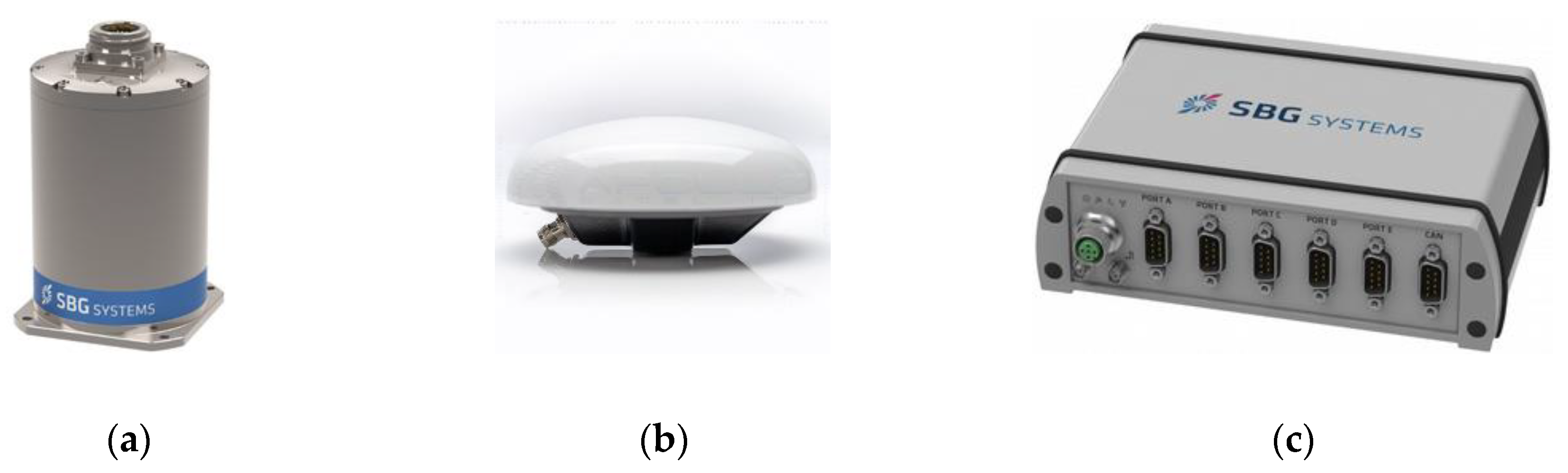
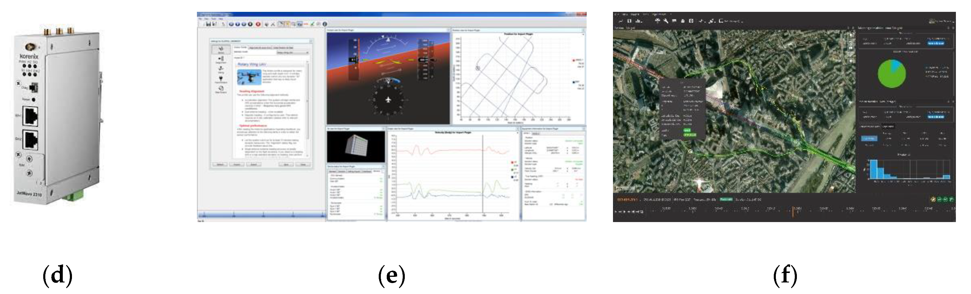
2.1. Measurement Equipment

As part of the InnoSatTrack research project, on 9 June 2021, surveys were conducted in Tricity. One of the aims was to determine the usefulness of GNSS/INS systems for railway measurements. To this end, one inertial navigation system was used: Ekinox2-U by the SBG Systems, which is comprised of the following components: an Inertial Measurement Unit (IMU) (Figure 1a); two antennas: an AERO GPS and GNSS Survey Antenna AT1675-382 (Figure 1b); a SplitBox computer system (Figure 1c); a modem enabling the reception of RTK/RTN corrections (Figure 1d); sbgCenter software (Figure 1e); and Qinertia software (Figure 1f) [64,65].
Moreover, the GNSS/INS system has functions which are important for the purpose of carrying out railway measurements [64,65]:
  • The Ekinox2-U system enables operation in two modes:
    Post-Processing (PP)—post-processed data using Inertial Explorer (IE) with at least Precise Point Positioning (PPP) data;
    RTK—Real-Time Kinematics with a typical 1 cm accuracy position.
  • The recording frequency for the data on angles, accelerations and position coordinates should be as high as possible. It is recommended that the IMU’s data should be recorded with a max frequency of 200 Hz.
As regards the accuracy characteristics of the GNSS/INS system, model Ekinox2-U are presented in Table 1 [65]. Note that the GNSS/INS system can be successfully used to carry out selected construction and geodetic tasks in railway engineering. As regards the access to the GNSS signal, it can be used (in both RTK and PP modes) to determine the rail track deformations. Based on the GNSS research conducted in the years 2009–2021 on railway lines [16], the authors assumed that the max horizontal position error for this group of measurements was no more than 1 cm. However, in the event of GNSS signal loss (up to 10 s), the Ekinox2-U system can be used in the process of a rapid stocktaking of existing rail tracks (3 cm (p = 0.95)).

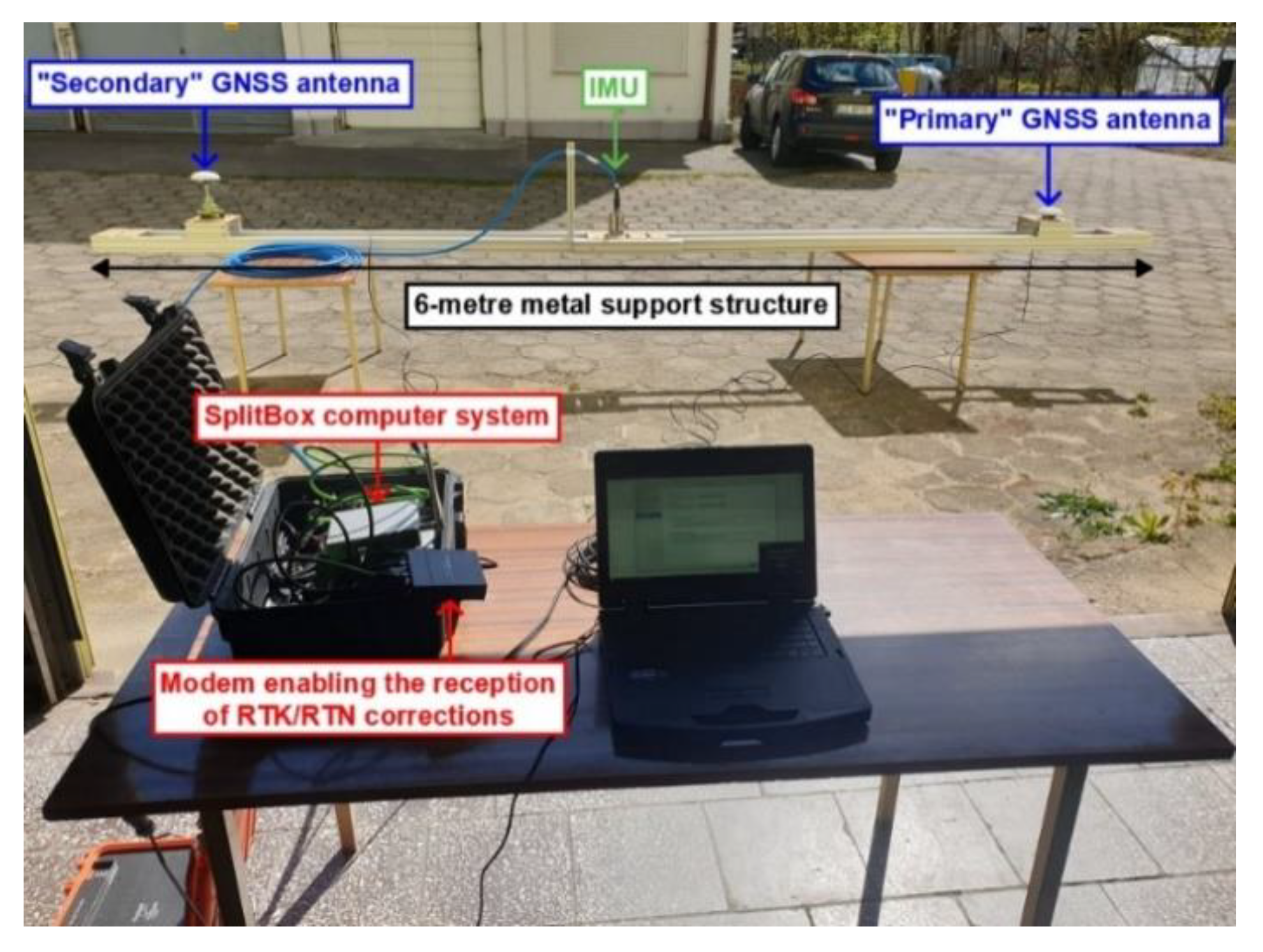
2.2. Calibration and Configuration of the GNSS/INS System

Before the measurements are started, the GNSS/INS system needed to be configured. To this end, a 6-metre metal support structure was used, on which the following were installed: an IMU, two external GNSS antennas (“Primary” and “Secondary”) mounted on geodetic tribrachs, a SplitBox system and a modem enabling the reception of RTK/RTN corrections (Figure 2). According to the SBG Systems manufacturer’s recommendations, it was established that the distance between the GNSS antennas would be 5 m (it should be at least 4 m in order to ensure an accurate course measurement of a vehicle in motion). The IMU was placed at the centre of the section connecting the two GNSS antennas, while the SplitBox system and the modem were also mounted on the metal support structure but between the “Secondary” antenna and the IMU.
In the next stage, it was possible to perform the GNSS/INS system calibration in motion. To this end, a Melex electric vehicle was used, on which a metal support structure was installed along with the tested inertial navigation system (Figure 3a). Before starting the calibration of the inertial navigation system, several parameters of the GNSS/INS system had to be set in the sbgCenter software, including, inter alia, the movement profile. Given the nature of the railway measurements, it was decided to select the “Automotive” mode dedicated to vehicle applications, i.e., those in which there are slight (slow) changes in the movement direction and the object’s velocity is less than 3 m/s. In addition, it was necessary to determine the axis orientation of the GNSS/INS system. A left-handed orthogonal coordinate system was adopted, whose zero point was present on the IMU’s cover. The axes of the system were oriented in such a way that the x-axis ran towards the front of the Mobile Measurement Platform (MMP), the y-axis was oriented towards the left side of the platform, while the z-axis ran towards the bottom part of the MMP. In order to be able to calibrate the inertial navigation system, it was necessary to determine the geometric relationships between the IMU and two GNSS antennas with an accuracy not worse than 20 cm. After performing the steps described above, the correctness of the performed GNSS/INS system configuration can be verified using the sbgCenter software (Figure 3b).
Then, it was possible to calibrate the GNSS/INS system. It is advised that the calibration should be carried out in motion for 15 min at an average speed of at least 10 km/h. Moreover, the movement direction needed to be constantly changed in order to calibrate all sensors such as accelerometers and gyroscopes. Movement in circles, ovals, or the so-called “eights” is recommended (Figure 4a). The calibration of the inertial navigation system was completed after 15 min of driving the Melex. During it, it was possible to precisely (from ±0 cm to ±3 cm) to determine the geometric relationships between the IMU and two GNSS antennas (Figure 4b).
After saving the above settings, the railway measurement campaign within Tricity was commenced in an unchanged form.

2.3. Location of GNSS/INS Measurements

Upon completion of the installation and implementation works, a measurement campaign was carried out on the rail tracks located in Tricity on the following lines: LK9 (Gdańsk Południe-Gdańsk Główny), LK202 (Gdańsk Główny-Gdańsk Wrzeszcz), LK248 (Gdańsk Wrzeszcz-Gdańsk Osowa) and LK201 (Gdańsk Osowa-Gdynia Główna). Due to the heavy traffic on the above routes and the necessity to adapt to the timetable, the data were recorded in sections of a considerable length. The few stops of the MMP were used to control and monitor the GNSS/INS data recording. The measurement sections, also referred to as sessions, are shown in Figure 5. During the stops at the railway stations Gdańsk Wrzeszcz and Gdańsk Osowa, the measurements were conducted in the stationary mode. On the other sections, the recording was carried out in the kinematic mode used for the purposes of this paper.

2.4. Realization of GNSS/INS Measurements

The measurement platform was separated from the towing vehicle by an additional empty carriage, which minimised the impact of terrain obstacles (in that case, the locomotive cab) on the recording of satellite data in the AERO GPS and GNSS Survey Antenna AT1675-382 receivers (Figure 6a). In the middle part of the carriage, the GNSS/INS system was installed on the metal support structure. At both the front and the rear of the MMP, a single metal support structure was mounted, on which three Trimble R10 receivers along with geodetic tribrachs were located. Meanwhile, the controllers that regulate GNSS receiver operation were placed in two yellow boxes (Figure 6b). During this mobile measurement campaign, the geodetic receivers were intended to be used to assess the usefulness of navigation satellite systems for application in rail transport.

2.5. Processing of GNSS/INS Data

The recorded GNSS/INS data were elaborated in the PP mode using the Qinertia software [66]. In order to carry out calculations, it was necessary to acquire synchronous satellite data from the nearest reference station located in Gdańsk (marked as GDSK), being part of the GNSS geodetic network VRSNet.pl of 9 June 2021, from the GPS time period from 05:00:00 to 15:00:00. The observation files are made available in the Receiver Independent Exchange System (RINEX) format [67] and contain observations from satellites of the GPS, GLONASS and Galileo systems recorded by the station’s receiver with a frequency of 1 Hz. It was then necessary to enter the input parameters that were determined during the calibration of the GNSS/INS system. In turn, it was necessary to select one of the following three methods for processing data:
  • Tight coupling Post-Processing Kinematic (PPK)—allows the highest GNSS/INS measurement accuracy to be obtained under conditions that are difficult in terms of satellite visibility. In order to be able to process GNSS/INS data using this method, it is necessary to have IMU data, raw GNSS data and the data from the GNSS geodetic network reference station;
  • Loosely coupling—enables the determination of the IMU’s coordinates when no GNSS signal is available. In order to be able to process GNSS/INS data using this method, it is necessary to have IMU data and the data from the GNSS geodetic network reference station;
  • PPK—allows the highest GNSS measurement accuracy to be obtained under conditions that are difficult in terms of satellite visibility. In order to be able to process GNSS data using this method, it is necessary to have raw GNSS data and the data from the GNSS geodetic network reference station.
Processing the GNSS/INS data in the PP mode was followed by the selection of three representative measurement sections on the Gdańsk-Gdynia route. They were selected in such a manner so as to enable the assessment of the Ekinox2-U system’s accuracy in sections varying in terms of terrain obstacles that limit the access to the GNSS signal:
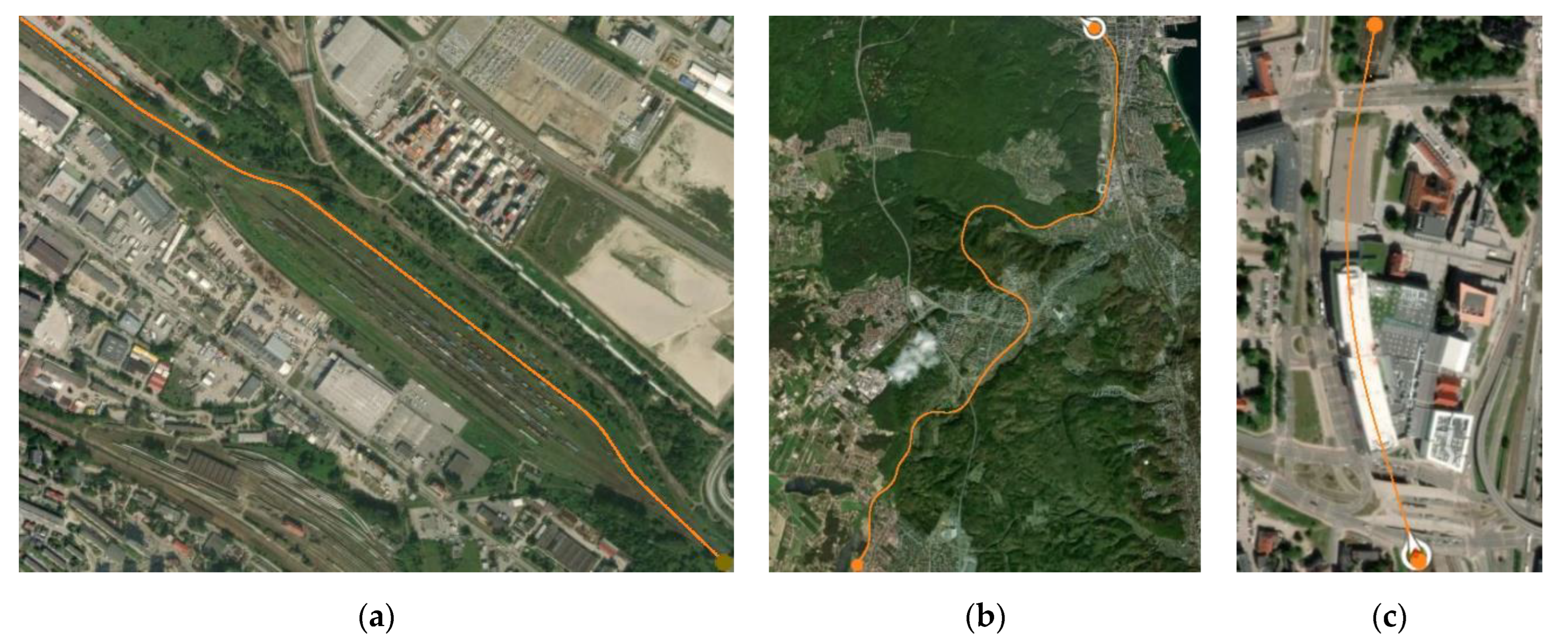
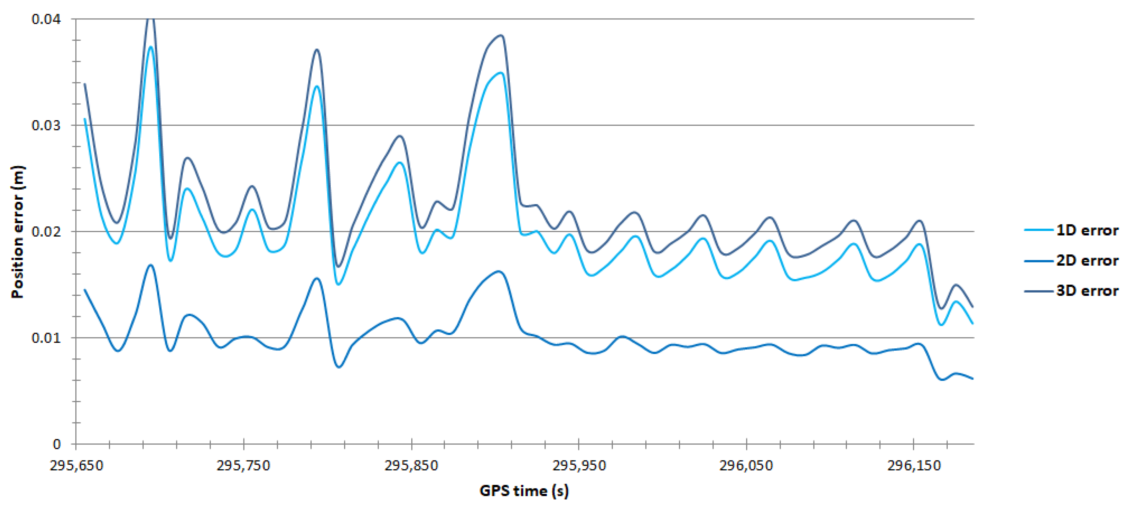
  • Section no. 1 (no terrain obstacles) was located on the railway line between the Radunia-Containers Ltd. in Gdynia and the Trasa Kwiatkowskiego (Figure 7a). Section no. 1 was approx. 2 km long. The measurement travel comprised long (several hundred metres), straight sections surrounded by virtually no terrain obstacles, the only exceptions being containers and bushes. The passage was performed on 9 June 2021 from 10:07:07 to 10:16:09 Coordinated Universal Time (UTC) (the duration of approx. 9 min).
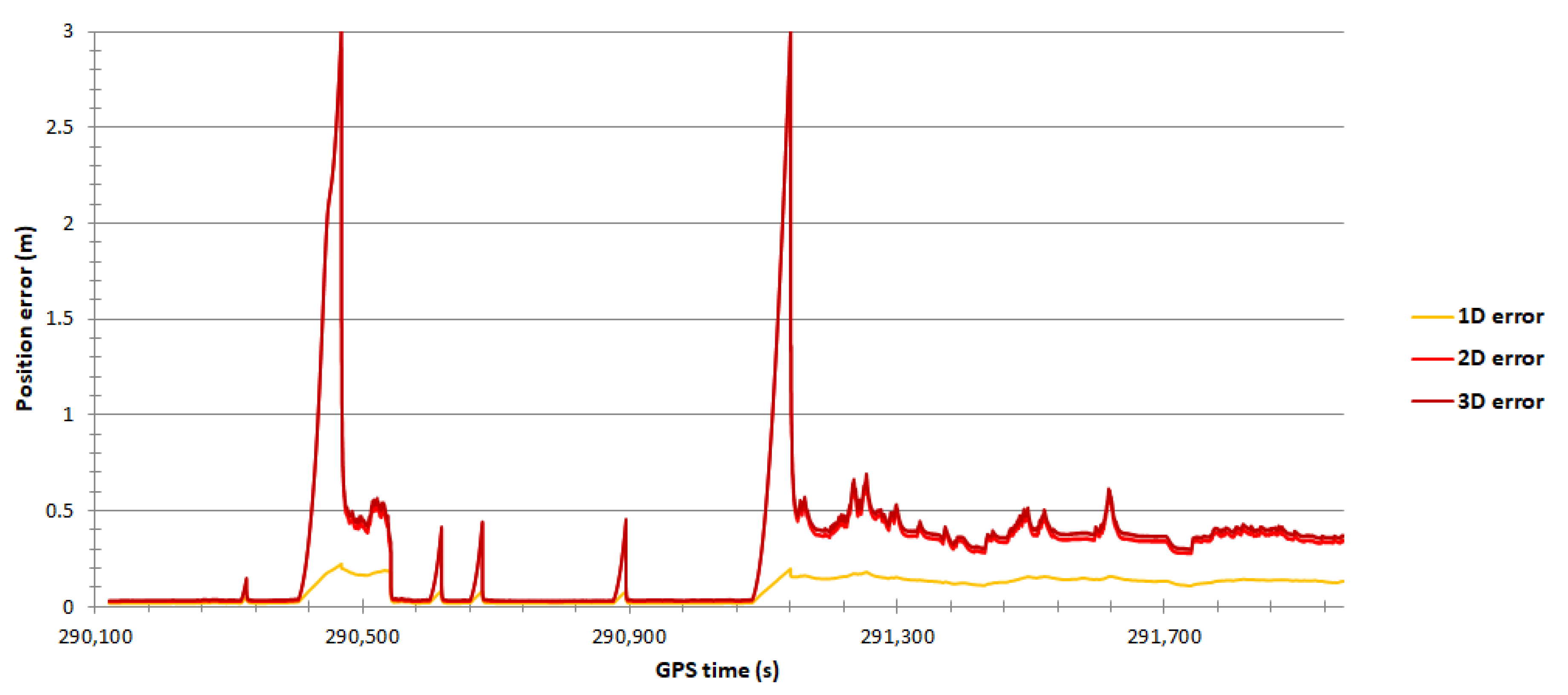
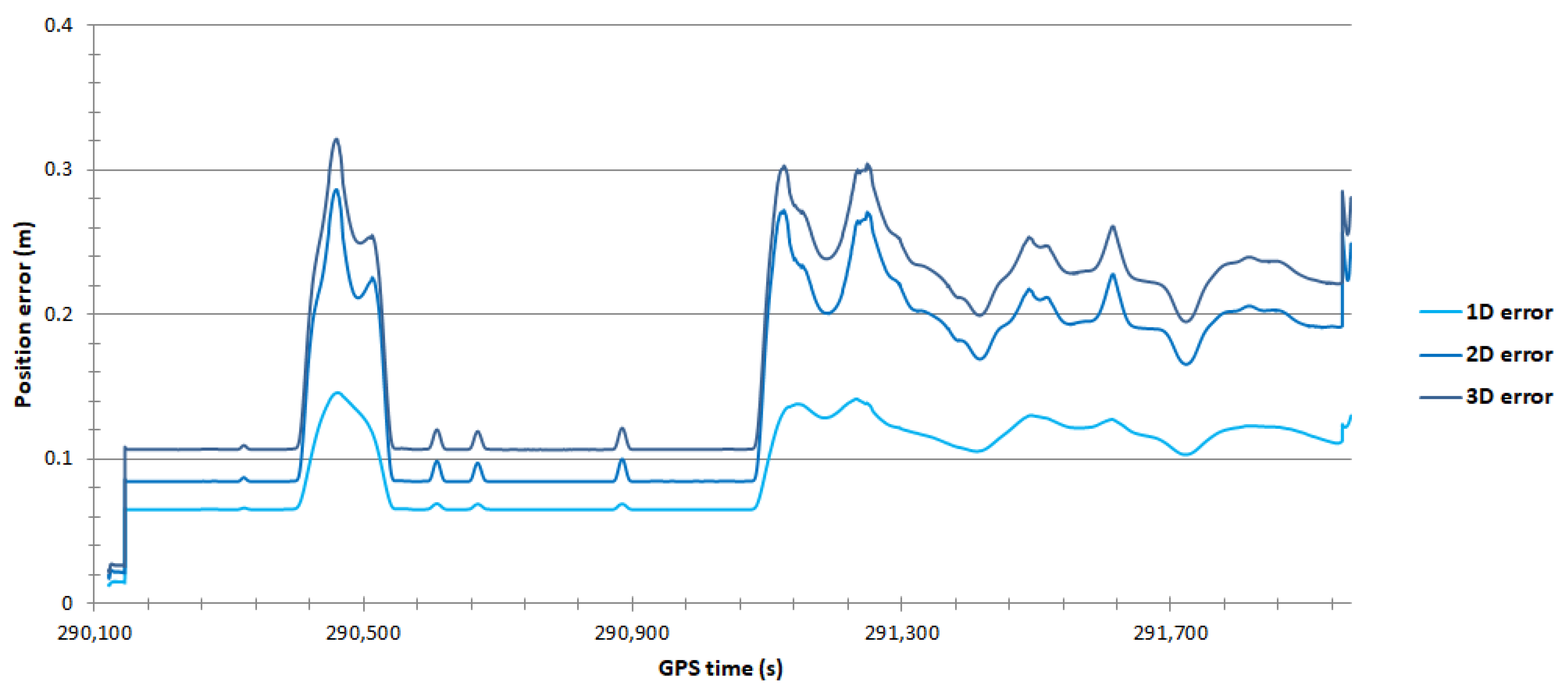
  • Section no. 2 (high building density) was located on the railway line between the Gdynia Główna railway station and the Gdańsk Osowa railway station (Figure 7b). Section no. 2 was approx. 15 km long. The measurement travel comprised circular curves with large turning angles. The second test section ran through numerous terrain obstacles, including multi-storey buildings and trees more than a dozen metres high. The passage was performed on 9 June 2021 from 08:35:03 to 09:05:50 UTC (the duration of approx. 31 min).
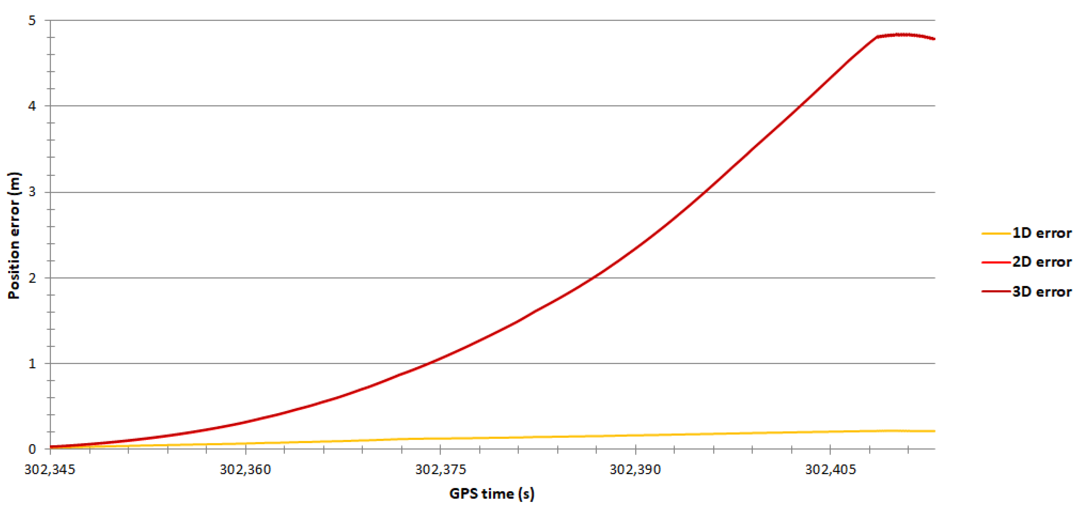
  • Section no. 3 (no access to GNSS signal) was located on the railway line in a tunnel in the centre of Gdańsk between the Gdańsk Śródmieście railway station and the Gdańsk Główny railway station (Figure 7c). Section no. 3 was approx. 600 m long. The measurement travel comprised a long circular curve with a small turning angle under the tunnel, where no GNSS signal was received. Two passages were performed on 9 June 2021 from 06:41:47 to 06:43:02 UTC (the duration of 75 s) and from 11:58:47 to 11:59:55 UTC (the duration of 68 s).
Each test section was subjected to an identical analysis of the obtained measurement results in order to formulate global conclusions. The IMU’s position errors were computed by the Qinertia software for two modes of the GNSS/INS system operation, i.e., PP and RTK. Subsequently, the errors were exported to text files. The files were then uploaded to the Mathcad software, where the position accuracy measures (RMS, Distance Root Mean Square (DRMS), Twice the Distance Root Mean Square (2DRMS), Circular Error Probable (CEP), Spherical Error Probable (SEP) and R68 and R95) were determined. From the perspective of navigation and transport applications linked to the process of controlling the object’s movement, the most important position accuracy measures are 2DRMS(2D) and R95(2D) [5,68].

3. Results

Table 2 shows the IMU’s position accuracy results obtained in section no. 1.
Note that the obtained position accuracy results in section no. 1 are higher for the data processed in the PP mode than for those processed in the RTK mode (Table 2). For example, the 2DRMS(2D) value is three times smaller for the data obtained in the PP mode (1.8 cm) than those obtained in the RTK mode (5.4 cm). What is more, the R95(2D) value is over 1.5 times smaller for the data acquired in the PP mode (1.7 cm) than those obtained in the RTK mode (2.8 cm).
Based on Figure 8, it should be stated that the variability of the 1D, 2D, and 3D position errors recorded in real-time is low along the entire section of the route. They fall within the following ranges: 1.8–2.3 cm (for the 1D position error), 2.6–2.9 cm (for the 2D position error) and 3.2–3.7 cm (for the 3D position error).
Considerably lower values of the 1D position error (approx. 1 cm) can be observed for the data processed in the PP mode (Figure 9). This error is up to two times smaller than that for the data recorded in the RTK mode. Moreover, it is worth noting that the 2D position error values in the PP mode are slightly lower than those in the RTK mode. They virtually do not exceed the value of 3 cm, while in the second half of section no. 1, they range from 1 to 1.5 cm.
Table 3 shows the IMU’s position accuracy results obtained in section no. 2.
Note that the obtained position accuracy results in section no. 2 are higher for the data processed in the PP mode than for those processed in the RTK mode (Table 3). For example, the 2DRMS(2D) value is three times smaller for the data obtained in the PP mode (32.6 cm) than those obtained in the RTK mode (96.1 cm). What is more, the R95(2D) value is over 2.5 times smaller for the data acquired in the PP mode (24.6 cm) than those obtained in the RTK mode (60 cm).
Figure 10 shows the high variability of the 2D and 3D position error values for the data recorded in the RTK mode, which is due to the type of terrain obstacles found along section no. 2. In the forested area (GPS time: 290,400–291,300 s) and the urbanised area (GPS time: 291,301–291,900 s), stepwise changes in the 2D and 3D position errors ranging from 0 to 3 m are noticeable. As regards the height accuracy, it also changes stepwise within the range from 0 to 20 cm.
A considerably lower variability in the 2D and 3D position error values can be observed for the data processed in the PP mode (Figure 11). In the forested area, the 2D and 3D position errors range from 20 to 30 cm. On the other hand, in the urbanised area, the 2D and 3D position errors oscillate around 10 cm, with a few exceptions reaching 20 to 30 cm. As regards the height accuracy, it is definitely more stabilised than the 2D and 3D position errors. In the forested area, it ranges from 10 to 14 cm, while in the urbanised area, the 1D position error is approx. 6 cm.
Table 4 shows the IMU’s position accuracy results obtained in section no. 3.
Note that the obtained position accuracy results in section no. 3 are considerably higher for the data processed in the PP mode than for those processed in the RTK mode (Table 4). For example, the 2DRMS(2D) value is nearly 10 times smaller for the data obtained in the PP mode (54.3 and 85.9 cm) than those obtained in the RTK mode (4.829 and 5.86 m). Moreover, the R95(2D) value is a dozen or so times smaller for the data obtained in the PP mode (32.8 and 64 cm) than those obtained in the RTK mode (4.811 and 5.886 m).
Figure 12 shows the high variability in the 2D and 3D position error values for the data recorded in the RTK mode. During the second trip through the tunnel, the 2D and 3D position errors increased linearly with the time elapsed since the moment the access to the GNSS signal was lost. At the end of the tunnel, these errors reached a value of approx. 5 m. As regards the 1D position error, it increased definitely slower than the 2D and 3D position errors. At the end of the tunnel, the error reached a value of approx. 20 cm.
It is worth noting that the position errors for the data processed in the PP mode are from a few to several times smaller than those for the data recorded in the RTK mode (Figure 13). For example, for approx. 15 s at both the entry to and exit from the tunnel, the 2D and 3D position errors increased from a few centimetres to over 30 cm. On the other hand, the 1D error ranged from 4 to 10 cm over the entire section of the route.

4. Discussion

The position error values obtained by the Ekinox2-U system are similar to (or even smaller than) the accuracy characteristics recommended by the SBG Systems. As for the non-built-up area, the 2DRMS(2D) measure was 5.4 cm (RTK) and 1.8 cm (PP), while the R95(2D) measure was 2.8 cm (RTK) and 1.7 cm (PP). As regards the area in which numerous terrain obstacles were found, e.g., multi-storey buildings or trees several metres tall, the 2DRMS(2D) measure was 96.1 cm (RTK) and 32.6 cm (PP), while the R95(2D) measure was 60 cm (RTK) and 24.6 cm (PP). For the tunnel, where there was no access to the GNSS signal for more than 60 s, the 2DRMS(2D) measures were 4.829–5.86 m (RTK) and 54.3–85.9 cm (PP), while the R95(2D) measures were 4.811–5.886 m (RTK) and 32.8–64 cm (PP).
Also note that the GNSS/INS data, which were converted in the post-processing mode, allowed the measurement accuracies to be considerably higher than in real-time. Where there was access to the GNSS signal, the 2DRMS(2D) and R95(2D) values increased by 1.5–3 times. However, where there was no access to the GNSS signal, the analysed position accuracy results decreased by up to several times.

5. Conclusions

This study has shown that the rapid development of GNSS/INS techniques, manifesting itself in recent years in the construction of new positioning systems and the modernisation of existing ones, as well as the implementation of new technical solutions for positioning, makes them usable for increasingly precise position determination, as well as in the kinematic mode.
Research has shown that GNSS/INS systems, which are supported by RTK receivers, can be used to carry out selected geodetic and construction tasks in railway engineering. The obtained measurement results indicate that the Ekinox2-U system can satisfy the accuracy requirements in the process of a rapid stocktaking of existing rail tracks (3 cm (p = 0.95)), as well as for design and construction works (10 cm (p = 0.95)), which is, however, determined by the type of terrain obstacles found in the test area. On the other hand, the system cannot be used to determine the place and extent of rail track deformations (1 cm, (p = 0.95)). The most important advantage of GNSS/INS systems over methods based only on GNSS systems is a significant increase (up to several times) in the positioning accuracy in signal-obstructed areas, such as tunnels.

Author Contributions

Conceptualization, M.S. and C.S.; data curation, M.S. and O.L.; formal analysis, P.D. and O.L.; investigation, M.S., C.S., A.S., P.B., P.D. and O.L.; methodology, A.S. and P.B.; supervision, C.S. and A.S.; validation, P.B. and P.D.; visualization, P.D. and O.L.; writing—original draft, M.S. and C.S.; writing—review and editing, A.S. and P.B. All authors have read and agreed to the published version of the manuscript.

Funding

This research was funded from the statutory activities of Gdynia Maritime University, grant numbers: WN/2022/PZ/05 and WN/PI/2022/03.

Institutional Review Board Statement

Not applicable.

Informed Consent Statement

Not applicable.

Data Availability Statement

Not applicable.

Conflicts of Interest

The authors declare no conflict of interest.

References

  1. Koc, W.; Specht, C. Results of Satellite Measurements of Railway Track. TTS Rail Transp. Tech. 2009, 7, 58–64. (In Polish) [Google Scholar]
  2. Koc, W.; Specht, C.; Jurkowska, A.; Chrostowski, P.; Nowak, A.; Lewiński, L.; Bornowski, M. Determining the Course of the Railway Route by Means of Satellite Measurements. In Proceedings of the 2nd Scientific-Technical Conference, Design, Construction and Maintenance of Infrastructure in Rail Transport (INFRASZYN 2009), Zakopane, Poland, 22–24 April 2009. (In Polish). [Google Scholar]
  3. Specht, M.; Specht, C.; Wilk, A.; Koc, W.; Smolarek, L.; Czaplewski, K.; Karwowski, K.; Dąbrowski, P.S.; Skibicki, J.; Chrostowski, P.; et al. Testing the Positioning Accuracy of GNSS Solutions during the Tramway Track Mobile Satellite Measurements in Diverse Urban Signal Reception Conditions. Energies 2020, 13, 3646. [Google Scholar] [CrossRef]
  4. Specht, C.; Wilk, A.; Koc, W.; Karwowski, K.; Dąbrowski, P.; Specht, M.; Grulkowski, S.; Chrostowski, P.; Szmagliński, J.; Czaplewski, K.; et al. Verification of GNSS Measurements of the Railway Track Using Standard Techniques for Determining Coordinates. Remote Sens. 2020, 12, 2874. [Google Scholar] [CrossRef]
  5. Specht, M.; Specht, C.; Dąbrowski, P.; Czaplewski, K.; Smolarek, L.; Lewicka, O. Road Tests of the Positioning Accuracy of INS/GNSS Systems Based on MEMS Technology for Navigating Railway Vehicles. Energies 2020, 13, 4463. [Google Scholar] [CrossRef]
  6. Wilk, A.; Specht, C.; Koc, W.; Karwowski, K.; Skibicki, J.; Szmagliński, J.; Chrostowski, P.; Dabrowski, P.; Specht, M.; Zienkiewicz, M.; et al. Evaluation of the Possibility of Identifying a Complex Polygonal Tram Track Layout Using Multiple Satellite Measurements. Sensors 2020, 20, 4408. [Google Scholar] [CrossRef] [PubMed]
  7. Czaplewski, K.; Wisniewski, Z.; Specht, C.; Wilk, A.; Koc, W.; Karwowski, K.; Skibicki, J.; Dabrowski, P.; Czaplewski, B.; Specht, M.; et al. Application of Least Squares with Conditional Equations Method for Railway Track Inventory Using GNSS Observations. Sensors 2020, 20, 4948. [Google Scholar] [CrossRef] [PubMed]
  8. Koc, W.; Wilk, A.; Specht, C.; Karwowski, K.; Skibicki, J.; Czaplewski, K.; Judek, S.; Chrostowski, P.; Szmagliński, J.; Dąbrowski, P.; et al. Determining Horizontal Curvature of Railway Track Axis in Mobile Satellite Measurements. Bull. Pol. Acad. Sci. Tech. Sci. 2021, 69, e139204. [Google Scholar]
  9. Wilk, A.; Koc, W.; Specht, C.; Skibicki, J.D.; Judek, S.; Karwowski, K.; Chrostowski, P.; Szmaglinski, J.; Dabrowski, P.; Czaplewski, K.; et al. Innovative Mobile Method to Determine Railway Track Axis Position in Global Coordinate System Using Position Measurements Performed with GNSS and Fixed Base of the Measuring Vehicle. Measurement 2021, 175, 109016. [Google Scholar] [CrossRef]
  10. Wilk, A.; Koc, W.; Specht, C.; Judek, S.; Karwowski, K.; Chrostowski, P.; Czaplewski, K.; Dabrowski, P.S.; Grulkowski, S.; Licow, R.; et al. Digital Filtering of Railway Track Coordinates in Mobile Multi–receiver GNSS Measurements. Sensors 2020, 20, 5018. [Google Scholar] [CrossRef]
  11. Akpinar, B.; Gulal, E. Multisensor Railway Track Geometry Surveying System. IEEE Trans. Instrum. Meas. 2012, 61, 190–197. [Google Scholar] [CrossRef]
  12. Gao, Z.; Ge, M.; Li, Y.; Shen, W.; Zhang, H.; Schuh, H. Railway Irregularity Measuring Using Rauch–Tung–Striebel Smoothed Multi-sensors Fusion System: Quad-GNSS PPP, IMU, Odometer, and Track Gauge. GPS Solut. 2018, 22, 36. [Google Scholar] [CrossRef]
  13. Kurhan, M.B.; Kurhan, D.M.; Baidak, S.Y.; Khmelevska, N.P. Research of Railway Track Parameters in the Plan Based on the Different Methods of Survey. Nauka Prog. Transp. 2018, 2, 77–86. [Google Scholar] [CrossRef] [Green Version]
  14. Li, Q.; Chen, Z.; Hu, Q.; Zhang, L. Laser-aided INS and Odometer Navigation System for Subway Track Irregularity Measurement. J. Surv. Eng. 2017, 143, 04017014. [Google Scholar] [CrossRef]
  15. Zhou, Y.; Chen, Q.; Niu, Q. Kinematic Measurement of the Railway Track Centerline Position by GNSS/INS/Odometer Integration. IEEE Access 2019, 7, 157241–157253. [Google Scholar] [CrossRef]
  16. Specht, C.; Koc, W. Mobile Satellite Measurements in Designing and Exploitation of Rail Roads. Transp. Res. Procedia 2016, 14, 625–634. [Google Scholar] [CrossRef] [Green Version]
  17. Chen, Q.; Niu, X.; Zhang, Q.; Cheng, Y. Railway Track Irregularity Measuring by GNSS/INS Integration. Navig. J. Inst. Navig. 2015, 62, 83–93. [Google Scholar] [CrossRef]
  18. Li, R.; Bai, Z.; Chen, B.; Xin, H.; Cheng, Y.; Li, Q.; Wu, F. High-speed Railway Track Integrated Inspecting by GNSS-INS Multisensor. In Proceedings of the 2020 IEEE/ION Position, Location and Navigation Symposium (PLANS 2020), Portland, OR, USA, 20–23 April 2020. [Google Scholar]
  19. Zhang, Q.; Chen, Q.; Niu, X.; Shi, C. Requirement Assessment of the Relative Spatial Accuracy of a Motion-constrained GNSS/INS in Shortwave Track Irregularity Measurement. Sensors 2019, 19, 5296. [Google Scholar] [CrossRef] [Green Version]
  20. Zhang, X.; Cui, X.; Huang, B. The Design and Implementation of an Inertial GNSS Odometer Integrated Navigation System Based on a Federated Kalman Filter for High-speed Railway Track Inspection. Appl. Sci. 2021, 11, 5244. [Google Scholar] [CrossRef]
  21. Reimer, C.; Müller, F.J.; Hinüber, E.L.V. INS/GNSS/Odometer Data Fusion in Railway Applications. In Proceedings of the 2016 DGON Intertial Sensors and Systems (ISS 2016), Karlsruhe, Germany, 20–21 September 2016. [Google Scholar]
  22. Bedkowski, J.; Nowak, H.; Kubiak, B.; Studzinski, W.; Janeczek, M.; Karas, S.; Kopaczewski, A.; Makosiej, P.; Koszuk, J.; Pec, M.; et al. A Novel Approach to Global Positioning System Accuracy Assessment, Verified on LiDAR Alignment of One Million Kilometers at a Continent Scale, as a Foundation for Autonomous DRIVING Safety Analysis. Sensors 2021, 21, 5691. [Google Scholar] [CrossRef]
  23. Elsheikh, M.; Abdelfatah, W.; Noureldin, A.; Iqbal, U.; Korenberg, M. Low-cost Real-time PPP/INS Integration for Automated Land Vehicles. Sensors 2019, 19, 4896. [Google Scholar] [CrossRef] [Green Version]
  24. Zhu, F.; Shen, Y.; Wang, Y.; Jia, J.; Zhang, X. Fusing GNSS/INS/Vision with a Priori Feature Map for High-precision and Continuous Navigation. IEEE Sens. J. 2021, 21, 23370–23381. [Google Scholar] [CrossRef]
  25. Brazeal, R.G.; Wilkinson, B.E.; Benjamin, A.R. Investigating Practical Impacts of Using Single-antenna and Dual-antenna GNSS/INS Sensors in UAS-Lidar Applications. Sensors 2021, 21, 5382. [Google Scholar] [CrossRef] [PubMed]
  26. Mwenegoha, H.A.; Moore, T.; Pinchin, J.; Jabbal, M. A Model-based Tightly Coupled Architecture for Low-cost Unmanned Aerial Vehicles for Real-time Applications. IEEE Access 2020, 1–20. [Google Scholar] [CrossRef]
  27. Naus, K.; Szymak, P.; Piskur, P.; Niedziela, M.; Nowak, A. Methodology for the Correction of the Spatial Orientation Angles of the Unmanned Aerial Vehicle Using Real Time GNSS, a Shoreline Image and an Electronic Navigational Chart. Energies 2021, 14, 2810. [Google Scholar] [CrossRef]
  28. Wang, Q.; Cui, X.; Li, Y.; Ye, F. Performance Enhancement of a USV INS/CNS/DVL Integration Navigation System Based on an Adaptive Information Sharing Factor Federated Filter. Sensors 2017, 17, 239. [Google Scholar] [CrossRef] [Green Version]
  29. Xia, G.; Wang, G. INS/GNSS Tightly-coupled Integration Using Quaternion-based AUPF for USV. Sensors 2016, 16, 1215. [Google Scholar] [CrossRef] [Green Version]
  30. Yan, W.; Zhang, Q.; Zhang, Y.; Wang, A.; Zhao, C. The Validation and Performance Assessment of the Android Smartphone Based GNSS/INS Coupled Navigation System. In Proceedings of the 12th China Satellite Navigation Conference (CSNC 2021), Nanchang, China, 22–25 May 2021. [Google Scholar]
  31. Li, N.; Guan, L.; Gao, Y.; Du, S.; Wu, M.; Guang, X.; Cong, X. Indoor and Outdoor Low-cost Seamless Integrated Navigation System Based on the Integration of INS/GNSS/LIDAR System. Remote Sens. 2020, 12, 3271. [Google Scholar] [CrossRef]
  32. Zhuang, Y.; Lan, H.; Li, Y.; El-Sheimy, N. PDR/INS/WiFi Integration Based on Handheld Devices for Indoor Pedestrian Navigation. Micromachines 2015, 6, 793–812. [Google Scholar] [CrossRef] [Green Version]
  33. Jing, S.; Zhan, X.; Liu, B.; Chen, M. Weak and Dynamic GNSS Signal Tracking Strategies for Flight Missions in the Space Service Volume. Sensors 2016, 16, 1412. [Google Scholar] [CrossRef] [Green Version]
  34. Barzaghi, R.; Carrion, D.; Pepe, M.; Prezioso, G. Computing the Deflection of the Vertical for Improving Aerial Surveys: A Comparison between EGM2008 and ITALGEO05 Estimates. Sensors 2016, 16, 1168. [Google Scholar] [CrossRef] [Green Version]
  35. Pytka, J.; Budzyński, P.; Józwik, J.; Michałowska, J.; Tofil, A.; Łyszczyk, T.; Błażejczak, D. Application of GNSS/INS and an Optical Sensor for Determining Airplane Takeoff and Landing Performance on a Grassy Airfield. Sensors 2019, 19, 5492. [Google Scholar] [CrossRef] [PubMed] [Green Version]
  36. Qian, C.; Liu, H.; Tang, J.; Chen, Y.; Kaartinen, H.; Kukko, A.; Zhu, L.; Liang, X.; Chen, L.; Hyyppä, J. An Integrated GNSS/INS/LiDAR-SLAM Positioning Method for Highly Accurate Forest Stem Mapping. Remote Sens. 2017, 9, 3. [Google Scholar] [CrossRef] [Green Version]
  37. El-Diasty, M. Development of Real-time PPP-based GPS/INS Integration System Using IGS Real-time Service for Hydrographic Surveys. J. Surv. Eng. 2016, 142, 1–8. [Google Scholar] [CrossRef]
  38. El-Diasty, M. Evaluation of KSACORS-based Network GNSS-INS Integrated System for Saudi Coastal Hydrographic Surveys. Geomat. Nat. Hazards Risk 2020, 11, 1426–1446. [Google Scholar] [CrossRef]
  39. Scheider, A.; Wirth, H.; Breitenfeld, M.; Schwieger, V. HydrOs—An Integrated Hydrographic Positioning System for Surveying Vessels. In Proceedings of the XXV FIG Congress 2014, Kuala Lumpur, Malaysia, 16–21 June 2014. [Google Scholar]
  40. Sun, Z.; Tang, K.; Wang, X.; Wu, M.; Guo, Y. High-speed Train Tunnel Navigation Method Based on Integrated MIMU/ODO/MC Navigation. Appl. Sci. 2021, 11, 3680. [Google Scholar] [CrossRef]
  41. Sun, Z.; Tang, K.; Wu, M.; Guo, Y.; Wang, X. High-speed Train Positioning Method Based on Motion Constraints Suppressing INS Error in Tunnel. J. Northwest. Polytech. Univ. 2021, 39, 624–632. [Google Scholar] [CrossRef]
  42. Chen, K.; Chang, G.; Chen, C. GINav: A MATLAB-based Software for the Data Processing and Analysis of a GNSS/INS Integrated Navigation System. GPS Solut. 2021, 25, 108. [Google Scholar] [CrossRef]
  43. Du, S.; Zhang, S.; Gan, X. A Hybrid Fusion Strategy for the Land Vehicle Navigation Using MEMS INS, Odometer and GNSS. IEEE Access 2020, 8, 152512–152522. [Google Scholar] [CrossRef]
  44. Elmezayen, A.; El-Rabbany, A. Ultra-low-cost Tightly Coupled Triple-constellation GNSS PPP/MEMS-based INS Integration for Land Vehicular Applications. Geomatics 2021, 1, 258–286. [Google Scholar] [CrossRef]
  45. Dong, P.; Cheng, J.; Liu, L. A Novel Anti-jamming Technique for INS/GNSS Integration Based on Black Box Variational Inference. Appl. Sci. 2021, 11, 3664. [Google Scholar] [CrossRef]
  46. Kujur, B.; Khanafseh, S.; Pervan, B. Detecting GNSS Spoofing of ADS-B Equipped Aircraft Using INS. In Proceedings of the 2020 IEEE/ION Position, Location and Navigation Symposium (PLANS 2020), Portland, OR, USA, 20–23 April 2020. [Google Scholar]
  47. Won, D.H.; Lee, E.; Heo, M.; Lee, S.-W.; Lee, J.; Kim, J.; Sung, S.; Jae, Y. Selective Integration of GNSS, Vision Sensor, and INS Using Weighted DOP Under GNSS-challenged Environments. IEEE Trans. Instrum. Meas. 2014, 63, 2288–2298. [Google Scholar] [CrossRef]
  48. Yang, L.; Li, Y.; Wu, Y.; Rizos, C. An Enhanced MEMS-INS/GNSS Integrated System with Fault Detection and Exclusion Capability for Land Vehicle Navigation in Urban Areas. GPS Solut. 2014, 18, 593–603. [Google Scholar] [CrossRef]
  49. Zhang, Z. Code and Phase Multipath Mitigation by Using the Observation-domain Parameterization and its Application in Five-frequency GNSS Ambiguity Resolution. GPS Solut. 2021, 25, 144. [Google Scholar] [CrossRef]
  50. Specht, C.; Specht, M.; Dąbrowski, P. Comparative Analysis of Active Geodetic Networks in Poland. In Proceedings of the 17th International Multidisciplinary Scientific GeoConference (SGEM 2017), Albena, Bulgaria, 27 June–6 July 2017. [Google Scholar]
  51. Mora, O.E.; Langford, M.; Mislang, R.; Josenhans, R.; Jorge Chen, J. Precision Performance Evaluation of RTK and RTN Solutions: A Case Study. J. Spat. Sci. 2020, 1–14. [Google Scholar] [CrossRef]
  52. Gargula, T. Adjustment of an Integrated Geodetic Network Composed of GNSS Vectors and Classical Terrestrial Linear Pseudo-observations. Appl. Sci. 2021, 11, 4352. [Google Scholar] [CrossRef]
  53. Walwer, D.; Calais, E.; Ghil, M. Data-adaptive Detection of Transient Deformation in Geodetic Networks. J. Geophys. Res. Solid Earth 2016, 121, 2129–2152. [Google Scholar] [CrossRef] [Green Version]
  54. Makar, A. Determination of Inland Areas Coastlines. In Proceedings of the 18th International Multidisciplinary Scientific GeoConference (SGEM 2018), Albena, Bulgaria, 2–8 July 2018. [Google Scholar]
  55. Makar, A. Dynamic Tests of ASG-EUPOS Receiver in Hydrographic Application. In Proceedings of the 18th International Multidisciplinary Scientific GeoConference (SGEM 2018), Albena, Bulgaria, 2–8 July 2018. [Google Scholar]
  56. Bousquet, O.; Lees, E.; Durand, J.; Peltier, A.; Duret, A.; Mekies, D.; Boissier, P.; Donal, T.; Fleischer-Dogley, F.; Zakariasy, L. Densification of the Ground-based GNSS Observation Network in the Southwest Indian Ocean: Current Status, Perspectives, and Examples of Applications in Meteorology and Geodesy. Front. Earth Sci. 2020, 8, 566105. [Google Scholar] [CrossRef]
  57. Krasuski, K.; Ciećko, A.; Bakuła, M.; Grunwald, G.; Wierzbicki, D. New Methodology of Designation the Precise Aircraft Position Based on the RTK GPS Solution. Sensors 2022, 22, 21. [Google Scholar] [CrossRef]
  58. Krasuski, K.; Mrozik, M.; Wierzbicki, D.; Ćwiklak, J.; Kozuba, J.; Ciećko, A. Designation of the Quality of EGNOS+SDCM Satellite Positioning in the Approach to Landing Procedure. Appl. Sci. 2022, 12, 1335. [Google Scholar] [CrossRef]
  59. Visconti, P.; Iaia, F.; De Fazio, R.; Giannoccaro, N.I. A Stake-out Prototype System Based on GNSS-RTK Technology for Implementing Accurate Vehicle Reliability and Performance Tests. Energies 2021, 14, 4885. [Google Scholar] [CrossRef]
  60. Bakuła, M. Study of Reliable Rapid and Ultrarapid Static GNSS Surveying for Determination of the Coordinates of Control Points in Obstructed Conditions. J. Surv. Eng. 2013, 139, 188–193. [Google Scholar] [CrossRef]
  61. Przestrzelski, P.; Bakuła, M. Performance of Real-time Network Code DGPS Services of ASG-EUPOS in North-eastern Poland. Tech. Sci. 2014, 17, 191–207. [Google Scholar]
  62. Bakuła, M.; Pelc-Mieczkowska, R.; Walawski, M. Reliable and Redundant RTK Positioning for Applications in Hard Observational Conditions. Artif. Satell. 2012, 47, 23–33. [Google Scholar] [CrossRef]
  63. Janos, D.; Kuras, P. Evaluation of Low-cost GNSS Receiver under Demanding Conditions in RTK Network Mode. Sensors 2021, 21, 5552. [Google Scholar] [CrossRef] [PubMed]
  64. SBG Systems. Ekinox Series. Available online: https://www.sbg-systems.com/products/ekinox-series/ (accessed on 25 April 2022).
  65. Stateczny, A.; Specht, C.; Specht, M.; Brčić, D.; Jugović, A.; Widźgowski, S.; Wiśniewska, M.; Lewicka, O. Study on the Positioning Accuracy of GNSS/INS Systems Supported by DGPS and RTK Receivers for Hydrographic Surveys. Energies 2021, 14, 7413. [Google Scholar] [CrossRef]
  66. SBG Systems. Qinertia. Available online: https://www.sbg-systems.com/products/qinertia-ins-gnss-post-processing-software/ (accessed on 25 April 2022).
  67. Gurtner, W.; Estey, L. RINEX: The Receiver Independent Exchange Format Version 2.11. Available online: https://files.igs.org/pub/data/format/rinex300.pdf (accessed on 25 April 2022).
  68. NovAtel. GPS Position Accuracy Measures. Available online: https://novatel.com/support/support-materials/application-notes (accessed on 25 April 2022).
Figure 1. Components of the GNSS/INS system, model Ekinox2-U, by the SBG Systems: IMU (a), GNSS antennas (b), SplitBox computer system (c), modem enabling the reception of RTK/RTN corrections (d), sbgCenter software (e) and Qinertia software (f) [64,65].
Energies 15 04094 g001aEnergies 15 04094 g001b
Figure 2. The arrangement of the GNSS/INS system on the metal support structure.
Energies 15 04094 g002
Figure 3. Melex electric vehicle used for the calibration of the GNSS/INS system (a) and the configuration window for the Ekinox2-U system in the sbgCenter software (b).
Energies 15 04094 g003
Figure 4. Melex movement trajectory (a) and the results of the Ekinox2-U system calibration (b) of 19 May 2021.
Energies 15 04094 g004
Figure 5. Sections of the GNSS/INS data recording in the kinematic mode: Gdańsk Południe-Gdańsk Wrzeszcz (a), Gdańsk Wrzeszcz-Gdańsk Osowa (c), Gdańsk Osowa-Gdynia Chylonia (e) and Gdynia Chylonia-Gdańsk Południe (f), as well as in the stationary mode: Gdańsk Wrzeszcz (b) and Gdańsk Osowa (d).
Energies 15 04094 g005
Figure 6. MMP (a) with the equipment used (b) during the railway measurement campaign conducted on 9 June 2021.
Energies 15 04094 g006
Figure 7. The division of the route into test sections: no. 1 (a), no. 2 (b) and no. 3 (c).
Energies 15 04094 g007
Figure 8. Variability in position errors recorded by the GNSS/INS system in the RTK mode in section no. 1.
Energies 15 04094 g008
Figure 9. Variability in position errors recorded by the GNSS/INS system in the PP mode in section no. 1.
Energies 15 04094 g009
Figure 10. Variability in position errors recorded by the GNSS/INS system in the RTK mode in section no. 2.
Energies 15 04094 g010
Figure 11. Variability in position errors recorded by the GNSS/INS system in the PP mode in section no. 2.
Energies 15 04094 g011
Figure 12. Variability in position errors recorded by the GNSS/INS system in the RTK mode in section no. 3.
Energies 15 04094 g012
Figure 13. Variability in position errors recorded by the GNSS/INS system in the PP mode in section no. 3.
Energies 15 04094 g013
Table 1. Accuracy characteristics of the GNSS/INS system, model Ekinox2-U, by the SBG Systems [65].
RMSETime That Has Elapsed Since the GNSS Signal Was Not Available
0 s10 s30 s
RTKPPRTKPPRTKPP
2D position (m)0.0100.0100.3500.0304.0001.500
Height (m)0.0200.0200.1500.0300.5000.500
Pitch, roll (°)0.0500.0200.1000.0200.1500.040
Course (°)0.0500.0400.1000.0500.1500.070
Table 2. Predictable accuracy of the Ekinox2-U system during the GNSS/INS measurements in section no. 1.
Statistics of Position ErrorType of Processing DataType of Registered Data
RTKPP
Number of measurements108,401542 Energies 15 04094 i001
RMS(ϕ)0.019 m0.007 m
RMS(λ)0.019 m0.005 m
RMS(h)0.019 m0.017 m
DRMS(2D)0.027 m0.009 m
2DRMS(2D)0.054 m0.018 m
DRMS(3D)0.033 m0.020 m
CEP(2D)0.027 m0.007 m
R68(2D)0.027 m0.005 m
R95(2D)0.028 m0.017 m
SEP(3D)0.033 m0.009 m
R68(3D)0.033 m0.018 m
R95(3D)0.035 m0.020 m
Table 3. Predictable accuracy of the Ekinox2-U system during the GNSS/INS measurements in section no. 2.
Statistics of Position ErrorType of Processing DataType of Registered Data
RTKPP
Number of measurements369,401369,401 Energies 15 04094 i002
RMS(ϕ)0.408 m0.122 m
RMS(λ)0.254 m0.109 m
RMS(h)0.107 m0.099 m
DRMS(2D)0.481 m0.163 m
2DRMS(2D)0.961 m0.326 m
DRMS(3D)0.492 m0.191 m
CEP(2D)0.324 m0.175 m
R68(2D)0.364 m0.197 m
R95(2D)0.600 m0.246 m
SEP(3D)0.345 m0.204 m
R68(3D)0.388 m0.231 m
R95(3D)0.621 m0.279 m
Table 4. Predictable accuracy of the Ekinox2-U system during the GNSS/INS measurements in section no. 3.
Statistics of Position ErrorType of Processing DataType of Registered Data
First TripSecond Trip
RTKPPRTKPP
Number of measurements15,00115,00113,60113,601 Energies 15 04094 i003
1st travel

Energies 15 04094 i004
2nd travel
RMS(ϕ)2.904 m0.305 m2.376 m0.236 m
RMS(λ)0.389 m0.303 m0.431 m0.134 m
RMS(h)0.167 m0.109 m0.143 m0.078 m
DRMS(2D)2.930 m0.430 m2.415 m0.271 m
2DRMS(2D)5.860 m0.859 m4.829 m0.543 m
DRMS(3D)2.935 m0.443 m2.419 m0.282 m
CEP(2D)1.577 m0.398 m1.340 m0.315 m
R68(2D)2.991 m0.534 m2.482 m0.322 m
R95(2D)5.886 m0.640 m4.811 m0.328 m
SEP(3D)1.584 m0.413 m1.347 m0.325 m
R68(3D)2.998 m0.548 m2.487 m0.335 m
R95(3D)5.891 m0.655 m4.816 m0.340 m
Publisher’s Note: MDPI stays neutral with regard to jurisdictional claims in published maps and institutional affiliations.

