Abstract
This paper investigates the nonlinear modeling and stability of a doubly-fed variable speed pumped storage power station (DFVSPSPS). Firstly, the mathematical model of DFVSPSPS with surge tank considering nonlinear pump turbine characteristics was derived and established. Then, Hopf bifurcation analysis of DFVSPSPS was performed. The stable region was identified and verified by example analysis. Moreover, the effect mechanism of nonlinear pump turbine characteristics on the stability of DFVSPSPS was explored. Finally, the influence of factors on the stability and dynamic response of DFVSPSPS was studied. The results indicate that the emerged Hopf bifurcation of DFVSPSPS is supercritical and the region on the low side of the bifurcation line is the stable region. Nonlinear head characteristics have a significant influence on the stability and dynamic response of DFVSPSPS. Nonlinear speed characteristics have an obvious effect on the stability and dynamic response of DFVSPSPS only under positive load disturbance and unstable surge tank. Nonlinear head characteristics are unfavorable for the stability of DFVSPSPS under positive load disturbance and favorable under negative load disturbance. A smaller flow inertia of penstock, a smaller head loss of penstock and a greater unit inertia time constant are favorable for the stability of DFVSPSPS. The stable region under the positive disturbance of active power is larger than that under the negative disturbance of active power. The time constant of the surge tank presents a saturation characteristic on the stability of DFVSPSPS.
1. Introduction
Vigorously developing renewable energy is an important strategic measure to deal with the problems of fossil fuel shortage, global warming and energy security. It is also an effective way of maintaining the sustainable development of national societies and economies. In recent years, the large-scale development and grid connection of intermittent renewable energy, such as wind power and photovoltaic, has created a serious threat to the safe and stable operation of the power grid [1,2]. Pumped storage power stations (PSPS) are the main regulating power supply in power systems [3]. It is of great importance to ensure the safety of the power grid, promote the consumption of renewable energy and promote the green and low-carbon transformation of energy [4,5]. Under the guidance of the goal of carbon peak and carbon neutralization, vigorously developing PSPS is an urgent task to implement the dual carbon goal [6].
At present, most PSPS use synchronous generators, which can only operate at a constant speed, resulting in a series of problems: (a) Under generator operation mode, the power regulation of the unit is slow; (b) The constant speed PSPS (CSPSPS) can only operate stably at the rated synchronous speed. When the operating head or load change, the unit speed will deviate from the optimal speed and the efficiency of the pump turbine will decrease, resulting in the deterioration of the unit operation; (c) In pumping mode, the input electromagnetic power lacks controllability. The variable speed pumped storage unit (VSPSU) is a new type of PSU, where an AC-excited asynchronous motor is used to replace the traditional DC-excited synchronous motor. The speed control of the unit is realized by changing the excitation current, which overcomes the disadvantage that the speed of the traditional PSU is not adjustable. Compared with the CSPSPS, the variable speed PSPS (VSPSPS) has the following advantages: (a) Accelerated regulation of active power; (b) Increased operation efficiency of the pump turbine in generator and pumping modes; (c) Widened operating range of the pump turbine; (d) Reduced cavitation process; (e) Increased stability and flexibility of pump turbine [7,8,9]. However, the modeling and operation control of VSPSPS are more complex due to the use of an AC-excited asynchronous motor and converter.
Most of the research into VSPSPS are focused on mathematical modeling, numerical simulation, operation stability, reliability, dynamic characteristics and control. Mathematical modeling is the foundation of numerical simulation, operation stability, reliability, dynamic characteristics and control. Stability is the primary requirement for the normal operation of the system. The relevant research on modeling, control and stability of VSPSPS is presented below.
Kuwabara et al. [10] took the 400 MW VSPSU of the Ohkawachi PSPS as an example to study the principal design and actual performance of the machine. The excellent dynamic performance and significant potential for contribution to the power system have been verified by field test data. Unsteady numerical simulations of the VSPSPS and the CSPSPS were performed and the corresponding dynamic performance was compared [11]. The simulation results demonstrate that VSPSPS improves power system stability. Tests of the VSPSPS in the Hydraulics Laboratory of the Polytechnic University of Madrid were also performed [8]. The results show that the VSPSPS has greater flexibility under off-designed conditions, which is mainly reflected by the improvements in efficiency, operation performance and operating range. Integrated modeling of VSPSPS and wind power was established with MATLAB/Simulink and validated by on-site measurements [12]. The advantage of VSPSPS for mitigating wind was analyzed by performance assessment. The different control strategies for VSPSPS connected to an isolated power system with high penetration of intermittent renewable energy were studied. The effect mechanism of penstock length and initial operating point on the dynamic performance was then investigated [13].
Relevant scholars have conducted in depth research into modeling, numerical simulation and control, and have done a lot of work. However, there has been relatively little work conducted on the stability of VSPSPS [14]. Guo et al. [15] derived a nonlinear mathematical model of VSPSPS. The influence of factors on stability were studied. However, nonlinear pump turbine characteristics were ignored and a linear model was used. A novel mathematical model of VSPSPS concerning the electromechanical transient model of doubly-fed induction (DFIG) was established and the stability was investigated based on Hopf bifurcation theory under turbine and pump modes [16,17]. Unfortunately, the pump turbine model was still linear. Zhu et al. [18] studied the stability of VSPSPS considering nonlinear head loss and the parameter sensitivity analysis of the model was analyzed systematically. However, the model did not consider pump turbine nonlinear characteristics.
From the above literature review, it can be shown that pump turbine nonlinear characteristics are often ignored and the simplified linear model is used in most of the existing research. However, the stability of a VSPSPS is affected by all the components of the hydropower station. Among those components, the pump turbine is the core component of PSPS and has an important effect on the stability of VSPSPS [19]. On the other hand, the surge tank also has an obvious influence on the stability and dynamic performance of VSPSPS but this influence is always neglected [20,21,22]. Therefore, it is difficult to fully understand the stability and dynamic characteristics of VSPSPS based on the simplified model; the effect mechanism of nonlinear pump turbine characteristics on stability and dynamic characteristics of VSPSPS can not be calculated. Moreover, most of the established models are focused on numerical simulation and control and are not suitable for stability analysis [14]. Therefore, a complete and reasonable mathematical model should be established for stability and dynamic characteristics analysis of VSPSPS. To overcome the above problems, using a doubly-fed VSPSPS (DFVSPSPS) as the research object, a novel nonlinear model of DFVSPSPS with surge tank and consideration of nonlinear pump turbine characteristics was established, and the dynamic performance and parameter sensitivity were studied. The novelty and innovation of the paper are:
- (1)
- The establishment of a novel, nonlinear model of DFVSPSPS considering surge tank and nonlinear pump turbine characteristics.
- (2)
- Clarification of the stability of DFVSPSPS based on theoretical analysis and numerical simulation.
- (3)
- Revealing of the effect mechanism of nonlinear pump turbine characteristics on the stability of DFVSPSPS.
- (4)
- Revealing of the influence of factors on the stability of DFVSPSPS.
The rest of this paper is organized as follows: The mathematical model of DFVSPSPS considering surge tank and nonlinear pump turbine characteristics is established in Section 2; in Section 3, the stability of DFVSPSPS is analyzed and verified by Hopf bifurcation theory and numerical simulation; in Section 4, the influence of nonlinear pump turbine characteristics on the stability and dynamic characteristics of DFVSPSPS are revealed; in Section 5, the influence of system parameters on the stability and dynamic characteristics of DFVSPSPS are studied; in Section 6, conclusions are given.
2. Nonlinear Modeling of DFVSPSPS
A typical layout schematic diagram of a DFVSPSPS is shown in Figure 1. In a DFVSPSPS system, the components include an upstream reservoir, headrace tunnel, surge tank, penstock, pump turbine, DFIG, converter and tailwater. The pump turbine is designed in a reversible way with high energy conversion efficiency in both power generation and pumping functions. The surge tank is set to decrease water hammer pressure in the penstock. The mathematical model of a DFVSPSPS is composed of the basic equations of components. The nomenclature for variables is shown in Appendix A.
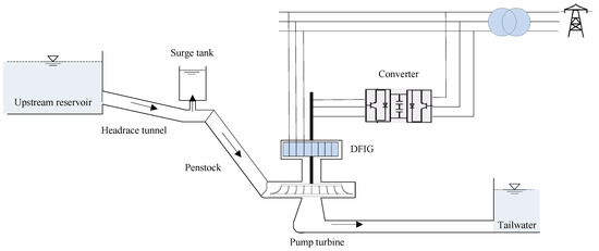
Figure 1.
Schematic diagram of a DFVSPSPS.
2.1. Hydraulic System
The dynamic equations of the hydraulic system, including headrace tunnel, surge tank and penstock, are determined by Newton’s Second Law of Motion.
Dynamic equation of headrace tunnel [23,24]:
Dynamic equation of surge tank [23,24]:
Dynamic equation of penstock [19]:
2.2. Model of DFIG Control System
2.2.1. Model of DFIG
DFIG is a complex system with strong nonlinearity and high coupling, therefore, it is difficult to model. To facilitate the research, the model of DFIG was established in a two-phase d-q synchronous coordinate. The basic equations of stator voltage and rotor voltage are [16]:
The equations of the stator and rotor flux linkages are represented as follows:
The torque equation and motion equation of the DFIG are represented as follows:
2.2.2. Control System
An AC-DC-AC bidirectional converter was adopted for this paper. The rotor-side converter adopts vector control based on the stator flux direction to realize the decoupling of active and reactive power of DFIG and control the active and reactive power independently. The grid-side converter adopts double closed-loop control based on the voltage direction to keep the DC bus voltage constant.
The control of the rotor side is shown as follows:
and are defined as follows:
The control of the grid side is shown as follows:
Now, the mathematical model of the DFIG control system was established, and consisted of Equations (4)–(12).
2.2.3. Model Simplifying of DFIG Control System
The response time of the electromagnetic transient, including the switching action of the power electronic devices and the dynamic process of the power converter, is very short. The electromechanical transient process is relatively slow (hundreds of milliseconds). Therefore, the model of the DFIG control system can be simplified by ignoring the electromagnetic transient process.
Under the reference coordinate system of stator flux linkage orientation, the d-q axis voltage and flux linkage have the following constraints:
Under operation, the voltage dip of the stator resistance is far less than the reactance voltage dip and counter electromotive force. Therefore, the stator resistance of the motor can be ignored. By substituting Rs = 0 and Equation (13) into Equations (4)–(5) we yield [16]:
where .
The dynamic characteristics of a DFVSPSPS are only related to the active power regulation. Therefore, under decoupling control, the grid voltage and the d-axis current can be considered constant. Consequently, in the study of stability and dynamic characteristics of DFVSPSPS, only the change of q-axis current is considered. For Equation (14), the equation for change of q-axis current can be obtained when the change of the d-axis current is ignored [16]:
The simplified model of DFIG can be obtained by combining Equations (6) and (15):
The response time of the electromagnetic transient is far less than the electromechanical transient process. Therefore, the dynamic process of the converter and the inner current loop can be ignored. A simplified DFIG control system model can be obtained further by combining Equations (8), (10) and (16):
2.3. Mechanical System
The governor is the core control component of the DFVSPSPS and consists of the controller and servosystem, which is mainly used to regulate the frequency, guide vane opening and power of a pump turbine. The traditional proportional-integral-derivative (PID) controller is used in the governor of a DFVSPSPS. The transfer function of the PID is defined as [25]:
The servosystem is the actuator of the governor, which is used to convert the electrical signal from the controller output into a mechanical signal to provide power to operate the guide vane. The servosystem can be described by a typical first-order transfer function:
The mechanical system consists of pump turbine and governor. The model for a pump turbine can be defined as a moment function and a flow function of guide vane opening, generator speed and water head, shown as follows [26]:
For small perturbation in the neighborhood of a steady-state operating point, the nonlinear pump turbine model shown in Equation (20) can be approximated as a linear model by using the Taylor series expansion without considering higher-order terms. Equation (20) can be rewritten as:
The relative values of the above equations are obtained:
Meanwhile, the six transfer coefficients are defined as follows:
Thus, Equation (22) can be expressed as [27,28]:
where six transfer coefficients of pump turbine ex, ey, eh, eqx, eqy and eqh are the partial derivatives of the torque and flow concerning speed n, guide vane opening y and water head h, respectively [29].
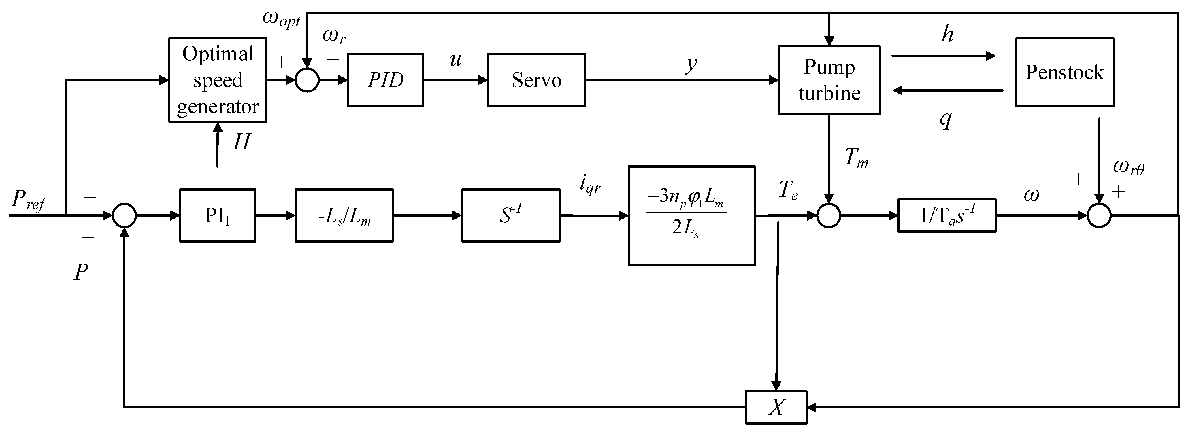
The mathematical model of the DFVSPSPS system not only includes the description of the dynamic characteristics of each component of the system, but also includes the control strategy, which is composed of Equations (1)–(3), Equations (17)–(19) and Equation (24). The control block diagram of the DFVSPSPS is shown in Figure 2.

Figure 2.
Control block diagram of the DFVSPSPS.
As shown in Figure 2, the optimal speed is obtained from the power reference value Pref and head h through the optimal speed generator, and the pump turbine can operate under the optimal working conditions. The control signal u of PID controller can be obtained from the difference between the optimal speed and the real-time speed . The guide vane opening y can then be obtained through the hydraulic servosystem to control the mechanical torque of the hydraulic turbine unit. The rotor side controls the active output of the generator according to the difference between the power reference value Pref and the real-time power P. The speed optimization of the optimal speed generator is used to obtain the optimal speed under different power reference value Pref and head h.
Therefore, according to the control block diagram of the system, the state space equation of the DFVSPSPS can be obtained from Equation (25):
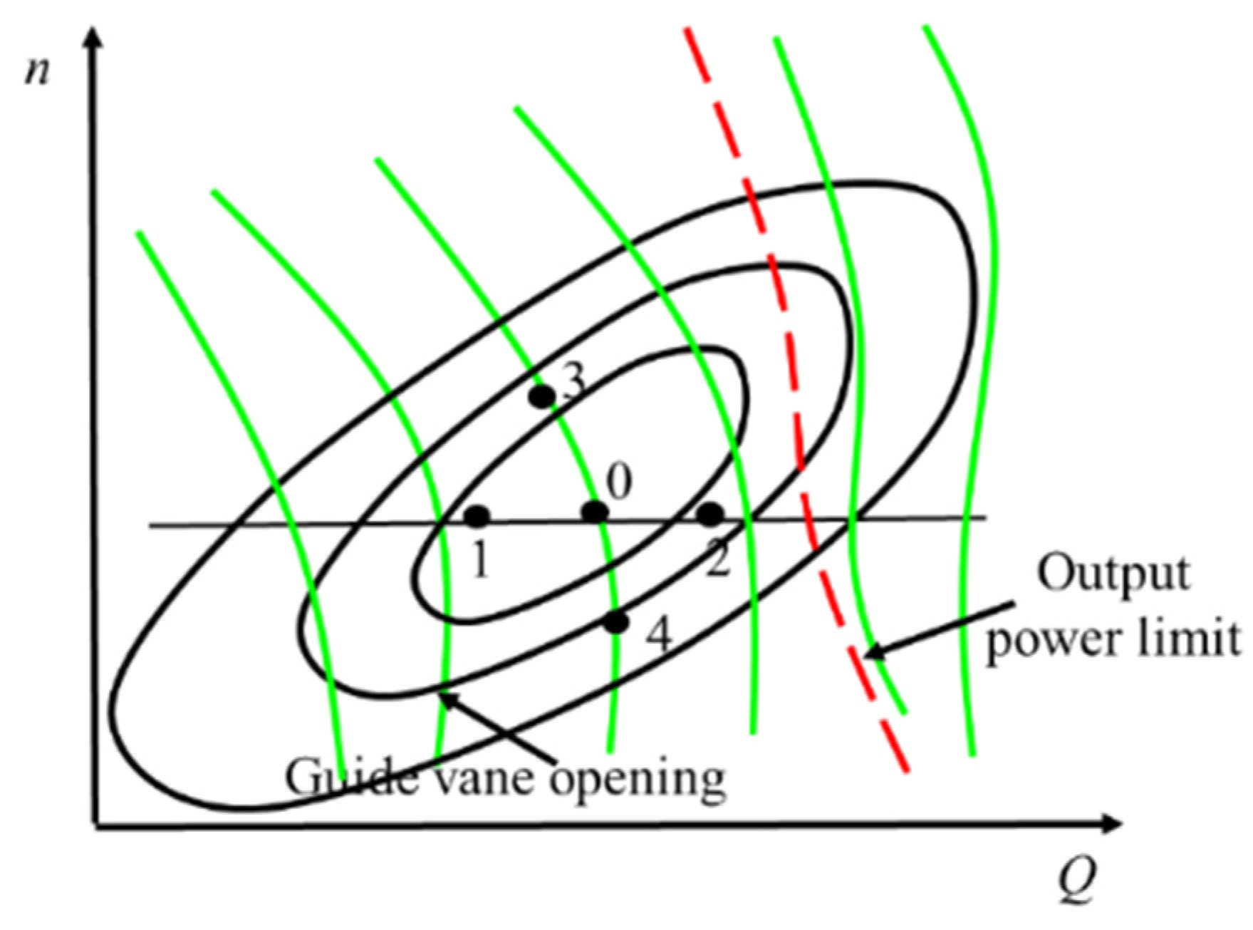
Equation (25) is an eighth-order state equation with eight state variables, , , , , , , and z. When the six transfer coefficients of pump turbine ex, ey, eh, eqx, eqy and eqh are considered as constants, the pump turbine is a linear model. The six transfer coefficients can be obtained from the model synthetic characteristic curve of the pump turbine. The synthetic characteristic curve of the pump turbine is shown in Figure 3. To calculate the six transfer coefficients in a certain steady operating point 0, the four neighboring operating points should be determined. In Figure 3, points 1 and 2 are located on the equal speed curve and points 3 and 4 are located on the equal guide vane opening curve. The six transfer coefficients can be defined as:
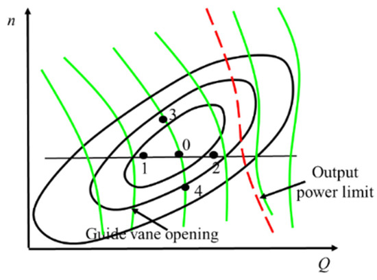
Figure 3.
The synthetic characteristic curve of a pump turbine.
From the above analysis, it can be seen that the values of six transfer coefficients are dependent on the steady operating condition point and characteristic curve of the pump turbine.
In the above mathematical model of DFVSPSPS shown in Equation (25), the six coefficients are considered as constants. However, during the transient process, the system parameters and operating condition point will change. Therefore, the values of transfer coefficients of the pump turbine will change. Therefore, there are some limitations and inaccuracies in the analysis of stability and dynamic characteristic of DFVSPSPS based on the linear pump turbine model, resulting in a large deviation in the calculation results. Considering the nonlinear characteristics of the pump turbine reflected by the changing six transfer coefficients with the change of operating conditions, the pump turbine nonlinear model should be deduced to analyze and reveal the influence of nonlinear pump turbine characteristics on the stability and dynamic characteristics of DFVSPSPS.
In the following paragraphs ey is taken as an example to illustrate the derivation process of the nonlinear analytical expression [30].
By using the same method, we can get [30]:
Then the nonlinear pump turbine model can be obtained:
From Equation (30), we can find that the moment equation and discharge equation are nonlinear and the six transfer coefficients can change with the head and speed. Therefore, the nonlinear pump turbine characteristics consist of nonlinear head characteristics and nonlinear speed characteristics. Considering the nonlinear pump turbine characteristics, a novel nonlinear DFVSPSPS is established in Equation (31):
3. Stability Analysis of DFVSPSPS
3.1. Hopf Bifurcation Theory
Hopf bifurcation theory is an effective method of investigating the stability of nonlinear systems, whose basic concept is described below [31,32].
For a nonlinear system expressed by differential equations , x is the state vector and is the bifurcation parameter. The equilibrium point of the system can be found by setting . The Jacobian matrix of the system at the equilibrium point can be obtained as , whose characteristic equation is:
where are the coefficients of characteristic equation and is the eigenvalue.
If the following conditions are met, the nonlinear system will achieve Hopf bifurcation [27]:
- (i)
- (ii)
- · ()
- (iii)
If the bifurcation parameter satisfies the above conditions, then is the bifurcation point of the system. At , the dynamic response of the system will oscillate periodically, and the phase space trajectory is a stable limit cycle. In addition, the type of bifurcation can be determined by the transversal coefficient . If , the occurred Hopf bifurcation is supercritical and the system is stable when . If , the occurred Hopf bifurcation is subcritical and the system is stable when .
3.2. Hopf Bifurcation Analysis of DFVSPSPS
For the eighth-order DFVSPSPS nonlinear model described by Equation (31) in this paper, the equilibrium point can be obtained by setting:
Then the Jacobian matrix of the system at the equilibrium point can be obtained and the detailed expression of is presented in Appendix B. The characteristic equation is:
3.3. Stable Region of DFVSPSPS
The Hopf bifurcation criteria for DFVSPSPS has been obtained in Section 3.2 as shown in Equation (35). The bifurcation line can be obtained by solving Equation (35), which consists of all bifurcation points on the parameter plane and divides the whole parameter plane into a stable region and an unstable region. The stable region of DFVSPSPS can be determined based on the bifurcation line and transversal coefficient . In this section, an actual DFVSPSPS is taken as a specific engineering example to present the application procedures of Hopf bifurcation analysis of DFVSPSPS. The stable region and dynamic response of DFVSPSPS can be clarified, and the essence and laws of stability of DFVSPSPS can be revealed based on the example analysis. The basic parameters of the DFVSPSPS are shown in Table 1.

Table 1.
Parameters of the DFVSPSPS.
The governor parameters Kp, Ki and Kd are the important variables and are closely related to the stability and dynamic characteristic of the DFVSPSPS. Therefore, the Kp-Ki plane is selected as the parameter plane and Kd is considered as a constant. Usually, Kp is chosen as the abscissa, Ki is chosen as the ordinate and the bifurcation parameter. For a given value of Kp, the value of Ki can be obtained by Equation (35).
In actual applications, the stable region of DFVSPSPS is determined by the following procedure:
Step 1: For a specific engineering example of DFVSPSPS, the equilibrium point of the system (Equation (31)) is calculated based on Equation (33);
Step 2: Calculate the Jacobian matrix of the system at the equilibrium point;
Step 3: Calculate the coefficients of the characteristic equation of the Jacobian matrix;
Step 4: For a value of Kp, calculate the corresponding bifurcation parameter Ki using Equation (35)
Step 5: For all the values of Kp, the repetition of Step 4 yields all the bifurcation points. The bifurcation line is then determined.
Step 6: Calculate the transversal coefficient for all the bifurcation points. The type of emerged Hopf bifurcation can then be determined.
The step disturbance of power is applied to excite the system, and the bifurcation line of the system can be determined based on the above six steps. The results are shown in Figure 4. Meanwhile, according to the obtained bifurcation points and the aforementioned definition of , the corresponding transversal coefficients are calculated and shown in Figure 5.

Figure 4.
Stable region of the DFVSPSPS.
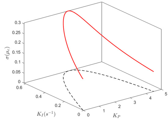
Figure 5.
Values of corresponding to the bifurcation line.
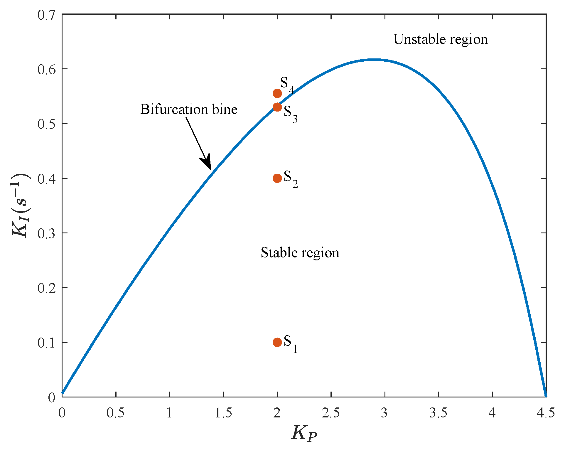
From Figure 4, we can see that the bifurcation line is a smooth curve, and the controller parameter KI of the bifurcation line presents a trend of first slowly increasing and then rapidly decreasing with the increase of KP. The KP-KI plane is divided into three parts, namely, the unstable region, stable region and critical stable region (bifurcation line). Figure 5 shows that the values of are greater than zero, which indicates that the emerged Hopf bifurcation of DFVSPSPS is supercritical. Therefore, the region at the lower side of the bifurcation line is the stable region and the other side is the unstable region. The bifurcation line and stable region can quantificationally and intuitively reflect the stability and dynamic characteristics of DFVSPSPS.
3.4. Numerical Simulation and Verification of Stability
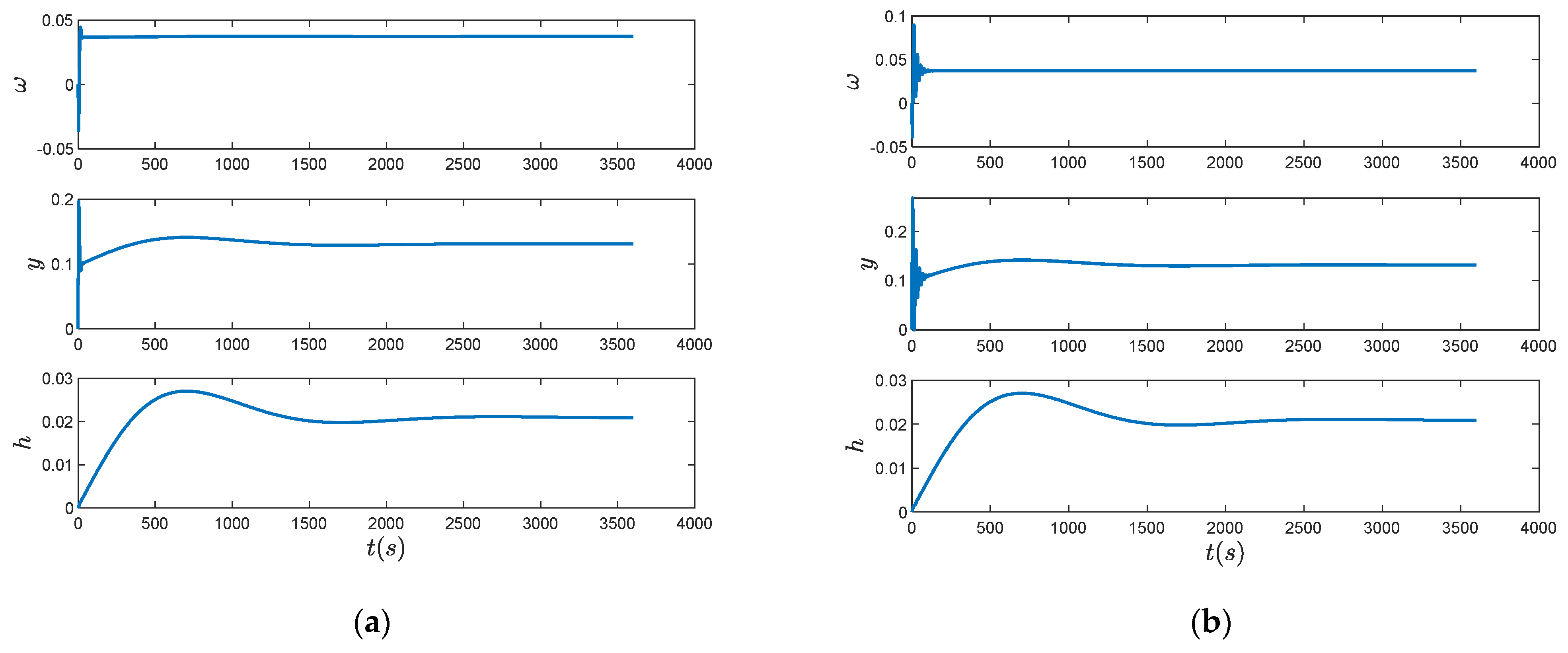
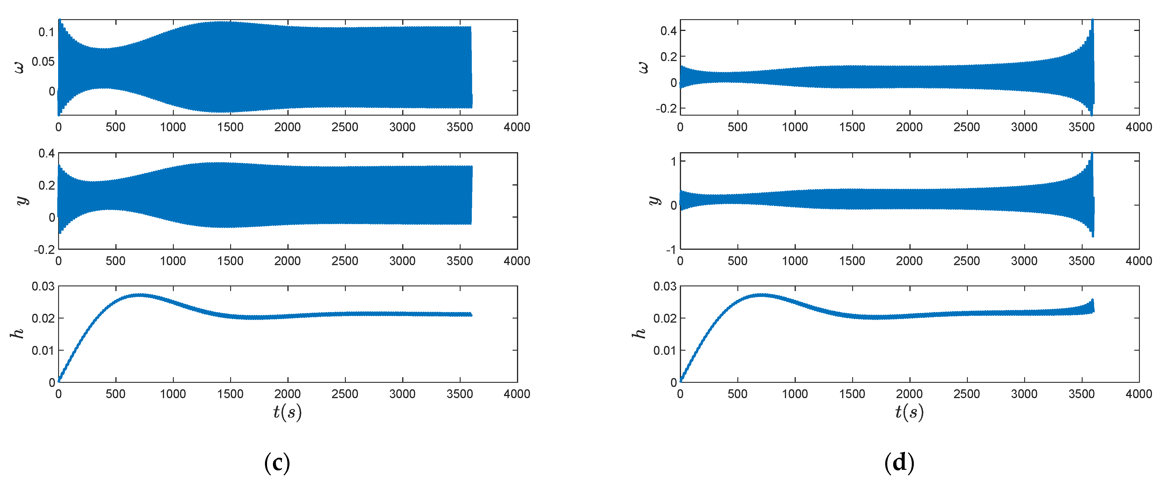
To verify the correctness of the obtained stable region in Section 3.3, and investigate the dynamic characteristic of DFVSPSPS under different governor parameter values, there are three points S1, S2 and S3 in Figure 4 which were selected as the representatives for numerical simulation of the dynamic response S1 and S2 are located within the stable region, S3 is located on the bifurcation line and S3 is located within the unstable region. To reflect the changes of state variables more intuitively, the phase space trajectories are also presented.
The Runge-Kutta method can be used to solve the nonlinear derivative equations of DFVSPSPS for numerical simulation, and the dynamic response process of the state variables x, y, and under the four points S1, S2, S3 and S4 are calculated, as shown in Figure 6. The corresponding phase space trajectories are shown in Figure 7. From Figure 6 and Figure 7, we can conclude that the numerical simulation results are consistent with the Hopf bifurcation theory analysis. For the stable state points S1 and S2, the dynamic responses of state variables present a damped oscillation and finally converge to a steady state. The phase space trajectories of S1 and S2 stabilize to the equilibrium point after several periods of damped attenuated motion. For the bifurcation point S3, the dynamic responses gradually enter a constant amplitude oscillation after several periods of oscillation. The corresponding phase space trajectory of S3 stabilizes at the limit cycle. For the unstable state point S4, the dynamic responses are divergent oscillation, and its phase space trajectory enters a gradually divergent motion.
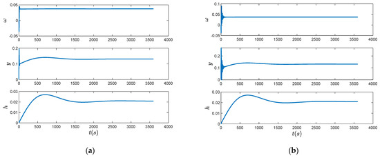
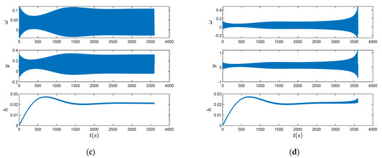
Figure 6.
Dynamic responses of state variables x, y, for S1, S2, S3 and S4. (a) S1; (b) S2; (c) S3; (d) S4.
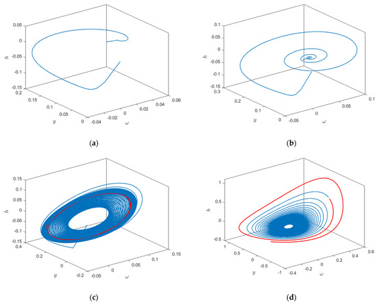
Figure 7.
Phase space trajectories of x, y, for S1, S2, S3 and S4. (a) S1; (b) S2; (c) S3; (d) S4.
4. Effect Mechanism of Nonlinear Pump Turbine Characteristics on Stability and Dynamic Characteristics
The stability and dynamic characteristics of DFVSPSPS have been investigated based on the engineering example in Section 3. In this section, we will focus on the effect mechanism of nonlinear pump turbine characteristics. In particular, the influence mechanism of nonlinear head characteristics and nonlinear speed characteristics on stability and dynamic characteristics of the DFVSPSPS are revealed.
A contrastive analysis is used to explore the effect mechanism of nonlinear head characteristics and nonlinear speed characteristics. Equation (30) is the nonlinear pump turbine model including nonlinear head characteristics and nonlinear speed characteristics, which is denoted as Model A. If nonlinear speed characteristics are ignored, the model of DFVSPSPS is denoted as Model B, where is replaced by . If the pump turbine only considers nonlinear head characteristics, the model of DFVSPSPS is denoted as Model C. The state equation can be obtained by replacing , and with , and , respectively. If both nonlinear head characteristics and nonlinear speed characteristics are ignored then a linear pump turbine model can be denoted as Model D, where , , and are replaced by , , and , respectively. The corresponding equations of pump turbines of Model B, Model C and Model D are presented as follows:
The stability and dynamic characteristics of DFVSPSPS under Model A have been analyzed in Section 3. The same stability analysis method can be used for Model B, Model C and Model D. Most research shows that the surge tank and the external disturbance have a significant influence on the stability of DFVSPSPS [19]. Therefore, different time constants of the surge tank and step load disturbance are considered, i.e., TF = 1500 s, TF =250 s, p = 0,1 and p = −0.1. The stable region and dynamic responses for Model A, Model B, Model C and Model D are shown in Figure 8 and Figure 9.
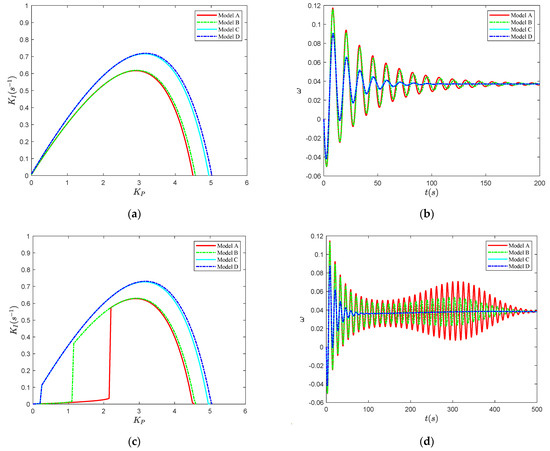
Figure 8.
Stable region and dynamic responses of DFVSPSPS under p = 0.10: (a) TF = 1500 s; (b) TF = 1500 s; (c) TF = 250 s; (d) TF = 250 s.
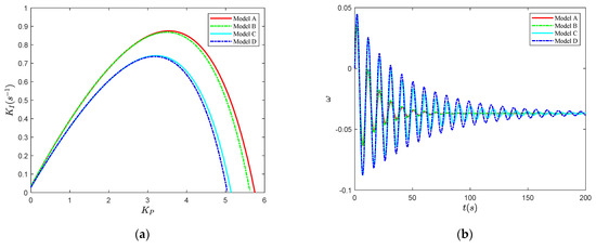
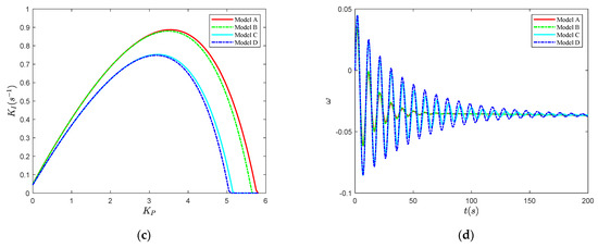
Figure 9.
Stable region and dynamic responses of DFVSPSPS under p = −0.10: (a) TF = 1500 s; (b) TF = 1500 s; (c) TF = 250 s; (d) TF = 250 s.
- When p = 0.1 and TF = 1500 s, the stable regions of Model A and Model B are almost coincident. Similarly, the stable regions of Model C and Model D are almost coincident. Moreover, the stable regions of Model A and Model B are significantly smaller than those of Model C and Model D. Therefore, under p = 0.1 and TF = 1500 s, we can see that nonlinear speed characteristics have almost no effect on stability, but nonlinear head characteristics have a significant effect on stability. Therefore, nonlinear pump turbine characteristics are mainly realized by the nonlinear head and nonlinear head characteristics are unfavorable for the stability of DFVSPSPS. The same conclusion can be drawn for dynamic response. Nonlinear speed characteristics have almost no effect on dynamic response, but nonlinear head characteristics have a significant effect on dynamic response. Comparing the dynamic responses of Model A and Model C in Figure 8b, nonlinear head characteristics can increase the oscillation amplitude and prolong the stability time. Nonlinear head characteristics have a negative effect on the dynamic performance of DFVSPSPS.
- For the DFVSPSPS under p = 0.1 and TF = 250 s, the stable regions of Model A and Model B are obviously smaller than that under p = 0.1 and TF = 1500 s. The stable regions of Model C and Model D are almost coincident with that under p = 0.1 and TF = 1500 s. However, the stable region of Model A is obviously smaller than Model B. The results indicate that nonlinear head characteristics have a significant effect on stability. Nonlinear speed characteristics have no effect on stability when the pump turbine does not contain nonlinear head characteristics as seen by comparing the stable regions of Model C and Model D. However, nonlinear speed characteristics have an obvious effect on stability when the pump turbine model contains nonlinear head characteristics as seen by comparing the stable regions of Model A and Model B. Therefore, under p = 0.1 and TF = 1500 s, nonlinear speed characteristics rely on nonlinear head characteristics. Nonlinear speed characteristics and nonlinear head characteristics are unfavorable for the stability of DFVSPSPS.
- For the DFVSPSPS under p = −0.1 and TF = 1500 s, the stable regions of Model A and Model B are almost coincident. The stable regions of Model C and Model D are also almost coincident. The stable region of Model C under p = 0.1 and TF = 1500 s is the same as that under p = −0.1 and TF = 1500 s. However, the stable regions of Model A and Model B are significantly larger than those of Model C and Model D. Therefore, under p = −0.1 and TF = 1500 s, we can draw the same conclusion as that under p = 0.1 and TF = 1500 s. Nonlinear speed characteristics have almost no effect on the stability and dynamic characteristics, but nonlinear head characteristics have a significant effect on the stability and dynamic characteristics. Nonlinear pump turbine characteristics are mainly realized by the nonlinear head. Nonlinear head characteristics are favorable for the stability dynamic characteristics of DFVSPSPS. Moreover, external disturbance only has an obvious effect on the stability of Model A and Model B and has no effect on the stability of Model C and Model D. Therefore, the influence of external disturbance on stability relies on nonlinear head characteristics. From Figure 9, we can see that the results under TF = 1500 s are the same as that under TF = 250 s.
5. Analysis of Influence Factors on Stability of DFVSPSPS
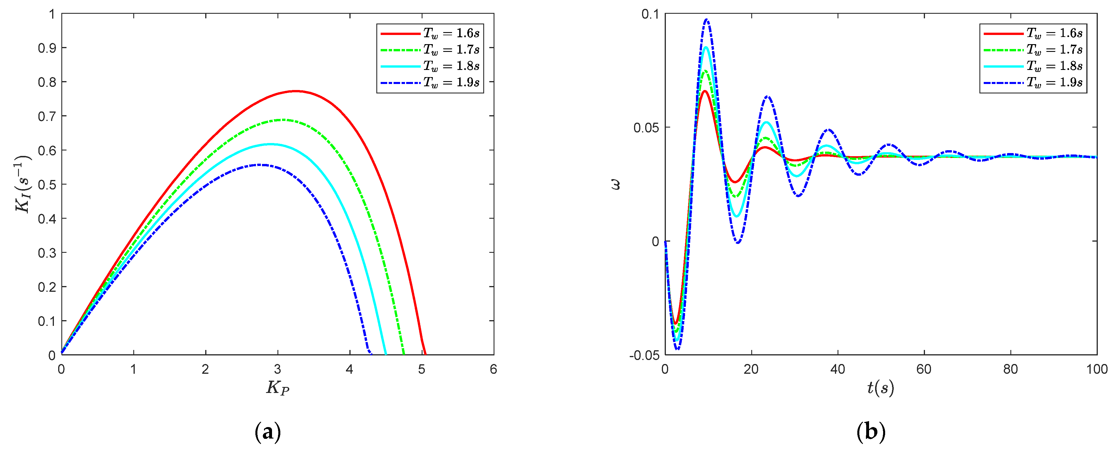
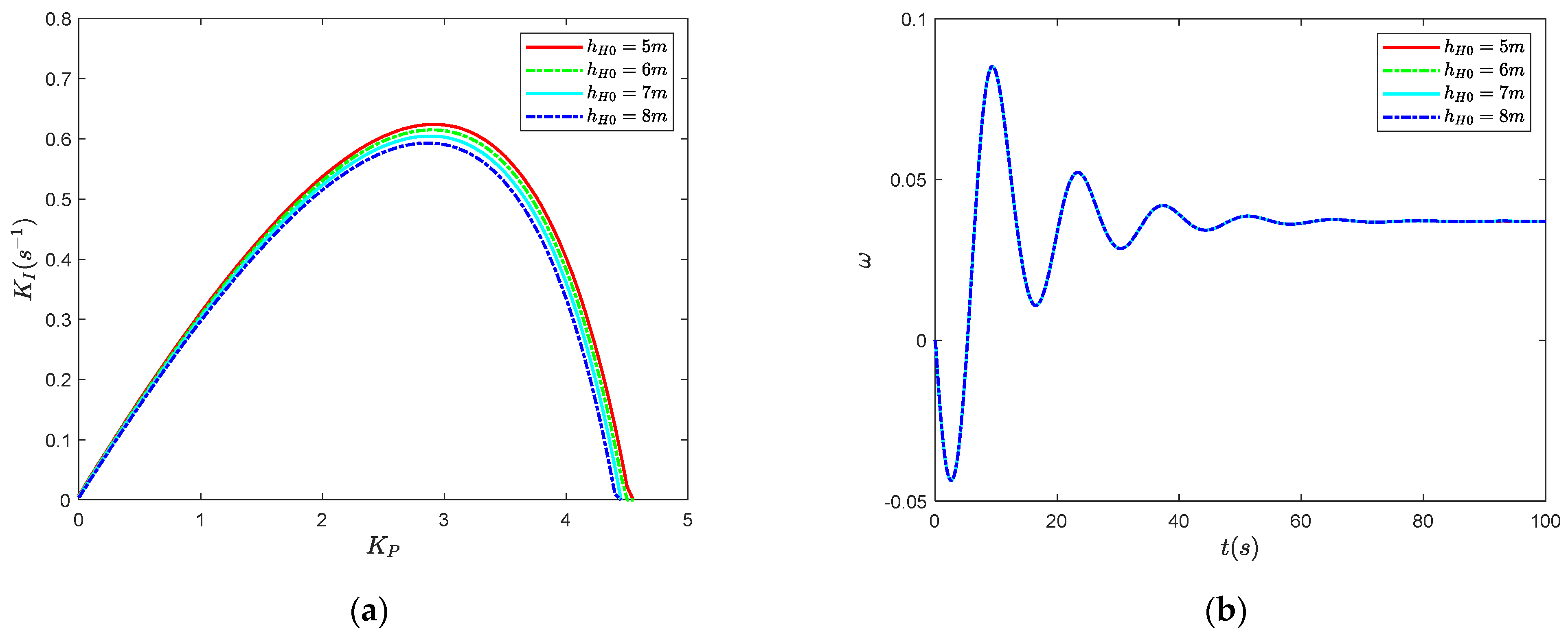
The effect mechanism of nonlinear pump turbine characteristics on the stability and dynamic characteristics of DFVSPSPS was investigated in Section 4. In this section, the effect mechanism of influence factors of DFVSPSPS on the stability and dynamic characteristics are further explored. The analysis results clarify the effect mechanism of influence factors on the stability and dynamic characteristics of DFVSPSPS, and provide guidance for the improvement of stability and dynamic performance of DFVSPSPS. Five important parameters of DFVSPSPS, Tw, hH0, Ta, p and TF, were chosen as the influence factors. The different values of the five influence factors were considered, and the other parameters remained unchanged, as shown in Table 1. For each value of the influence factors, the stable region of DFVSPSPS was obtained and a state point under the stable region was chosen for numerical simulation of the dynamic response of . The stable region and dynamic response of DFVSPSPS are shown in Figure 10, Figure 11, Figure 12, Figure 13 and Figure 14.
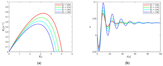
Figure 10.
Effect of Tw on stability and dynamic characteristics: (a) Stable region; (b) Dynamic response.
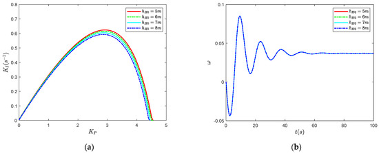
Figure 11.
Effect of hH0 on stability and dynamic characteristics: (a) Stable region; (b) Dynamic response.

Figure 12.
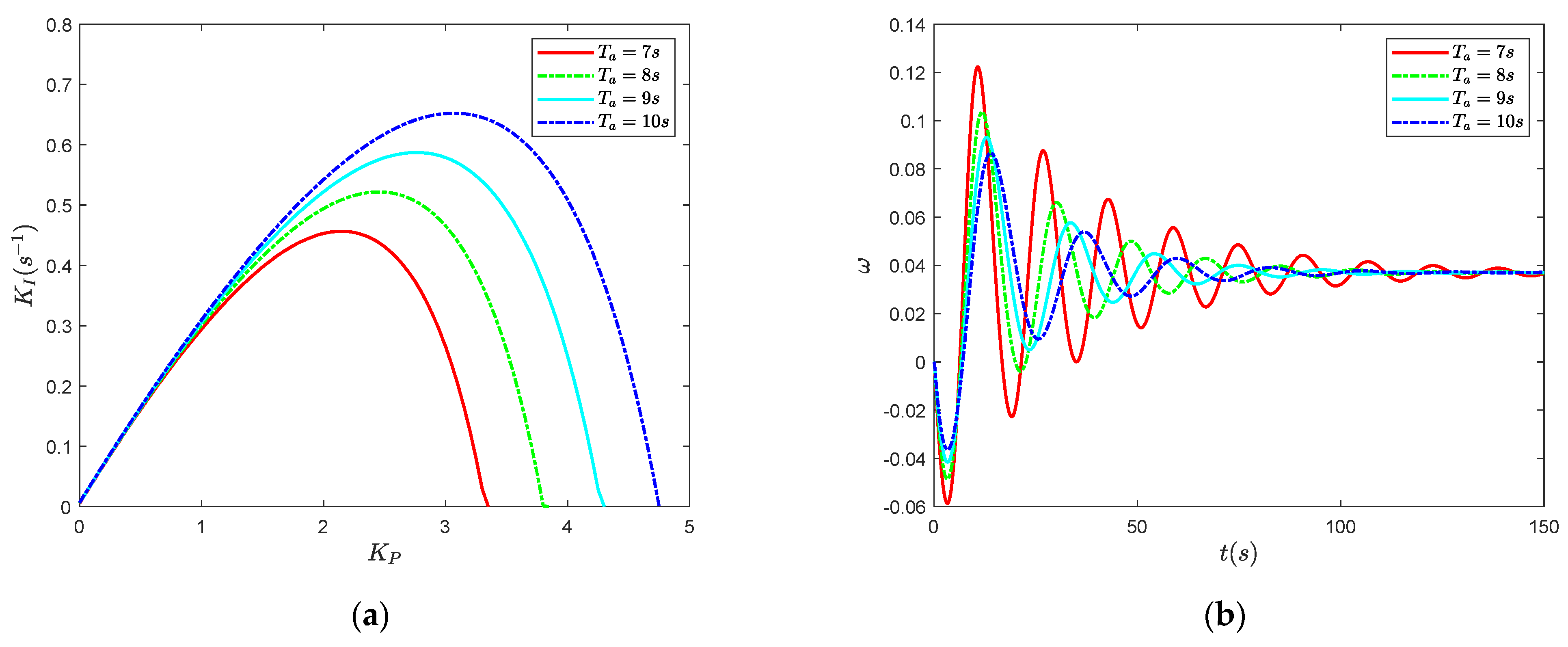
Effect of Ta on stability and dynamic characteristics: (a) Stable region; (b) Dynamic response.
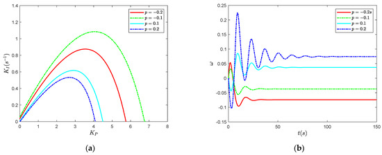
Figure 13.
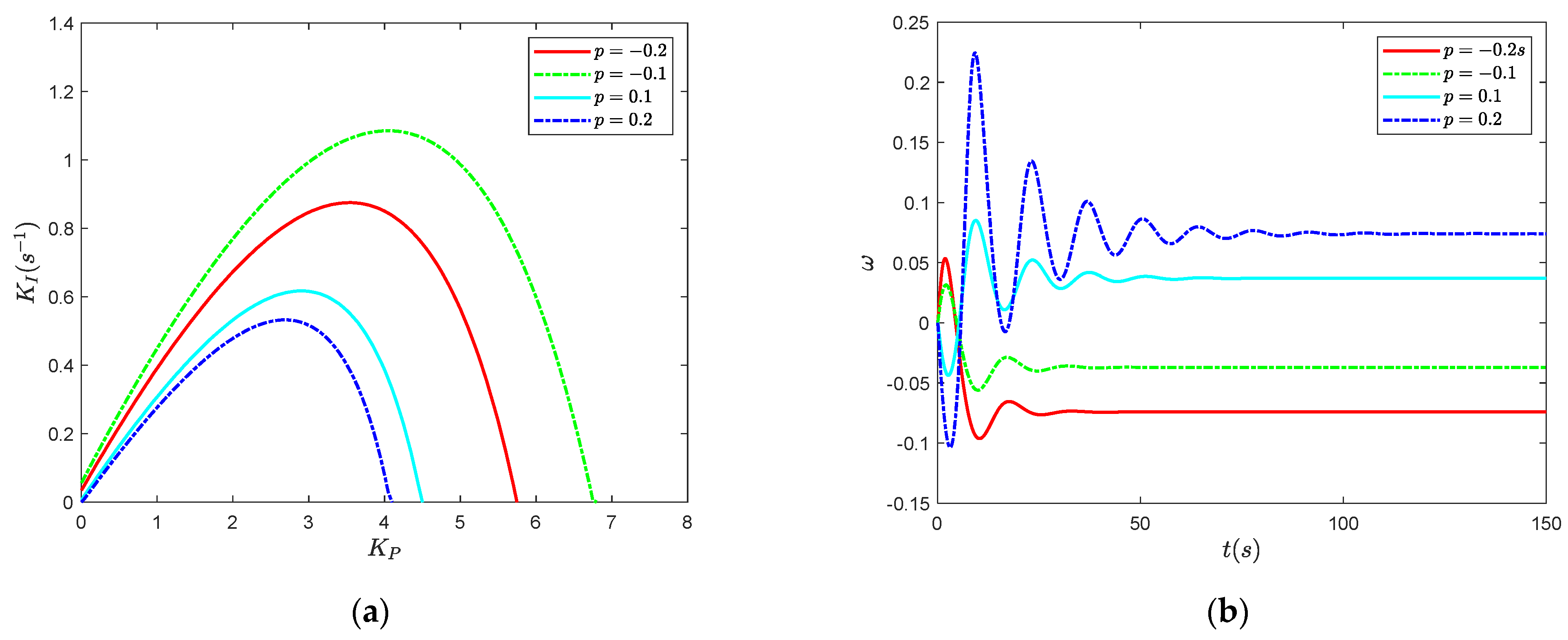
Effect of p on stability and dynamic characteristics: (a) Stable region; (b) Dynamic response.
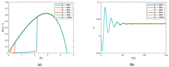
Figure 14.
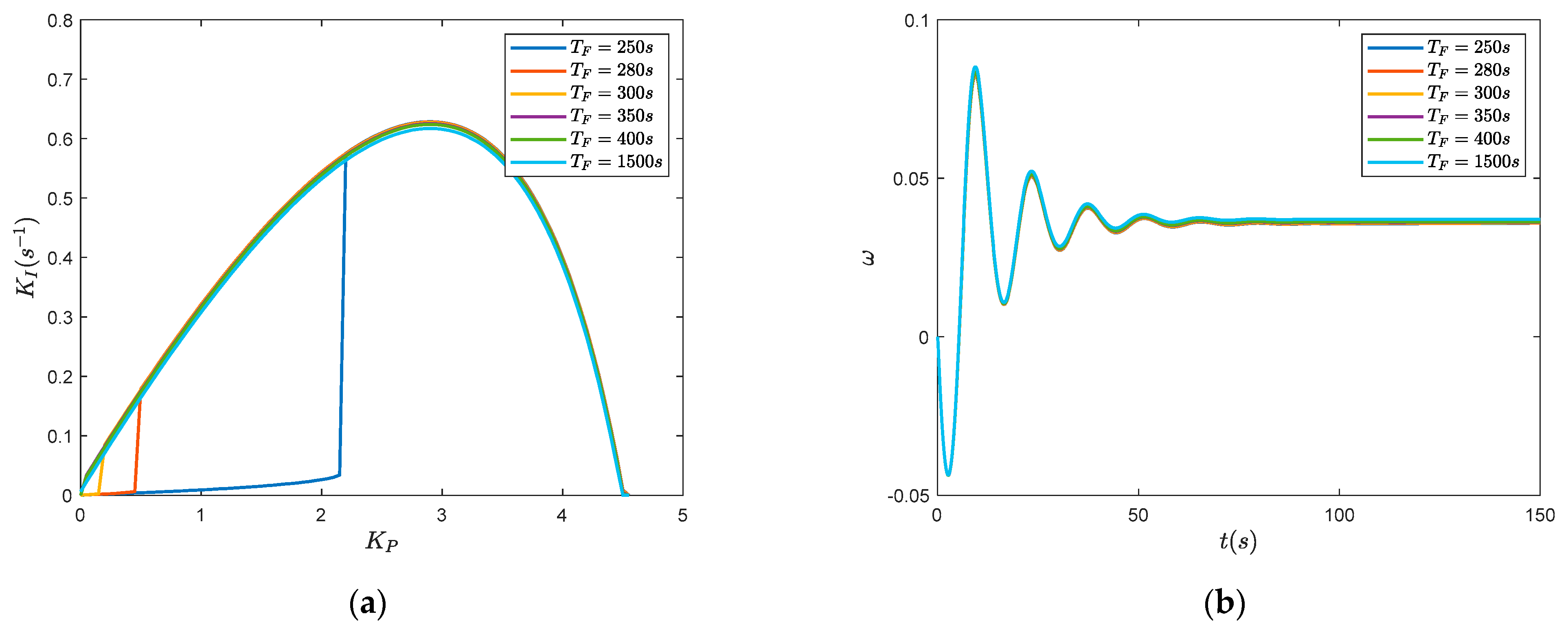
Effect of TF on stability and dynamic characteristics: (a) Stable region; (b) Dynamic response.
- Effect of Tw on stability and dynamic characteristics of DFVSPSPS
Tw was set as 1.6 s, 1.7 s, 1.8 s and 1.9 s, respectively. The stable regions and dynamic responses are shown in Figure 10. From Figure 10a, it can clearly be seen that Tw has a significant effect on stability. The stable region becomes obviously smaller as Tw increases. Therefore, a smaller Tw is favorable for the stability of DFVSPSPS. Tw also has a significant effect on the response process shown in Figure 10b. As Tw increases, the dynamic performance of DFVSPSPS becomes significantly worse.
- Effect of hH0 on stability and dynamic characteristics of DFVSPSPS
hH0 was set as 5 m, 6 m, 7 m and 8 m, respectively. The stable regions under different hH0 are shown in Figure 11a. Figure 11a shows that hH0 has an obvious effect on the stability of DFVSPSPS. The stable region becomes smaller as hH0 increases.Therefore, a smaller hH0 is favorable for the stability of DFVSPSPS. However, from Figure 11b, the dynamic responses are coincident under different values of hH0. Therefore, hH0 has almost no effect on the dynamic response of DFVSPSPS.
- Effect of Ta on stability and dynamic characteristics of DFVSPSPS
Ta was set as 7 s, 8 s, 9 s and 10 s, respectively. The stable regions and dynamic responses are shown in Figure 12. From Figure 12a, it can clearly be seen that Ta has a significant effect on stability. The stable region becomes obviously larger as Ta increases. Therefore, a larger Ta is favorable for the stability of DFVSPSPS. Ta also has a significant effect on the response as shown in Figure 12b. As Ta increases, the dynamic performance of DFVSPSPS becomes significantly improved.
- Effect of p on stability and dynamic characteristics of DFVSPSPS
p was set as −0.2, −0.1, 0.1 and 0.2, respectively. The stable regions and dynamic responses are shown in Figure 13. From Figure 13a, it can clearly be seen that p has a significant effect on stability. The stable region under p < 0 is larger than that under p > 0. Moreover, when p < 0, the stable region becomes obviously larger as p increases. However, when p > 0, the stable region becomes obviously smaller with increasing p. Therefore, a larger absolute value of p is favorable for the stability of DFVSPSPS.
p also has a significant effect on the response process of as shown in Figure 13b. When p > 0, the response process of first decreases and then increases. The oscillation amplitude becomes larger with increasing p. When p < 0, the response process of first increases and then decreases. The oscillation amplitude becomes larger with decreasing p. After several periods, the response process of stabilizes at a positive steady-state value. Therefore, the oscillation amplitude relies on the absolute value of p and the sign of the steady-state value depends on the sign of p.
- Effect of TF on stability and dynamic characteristics of DFVSPSPS
TF was set as 270 s, 280 s, 300 s, 350 s, 400 s and 1500 s, respectively. The stable regions under different TF are shown in Figure 14a. Figure 14a shows that TF has an obvious effect on the stability of DFVSPSPS when TF < 350. The stable region becomes larger as TF increases. However, when TF > 350, the stable region keeps almost unchanged with increasing TF. Therefore, a larger TF is favorable for the stability of DFVSPSPS. However, from Figure 14b, the dynamic responses of are coincident under different values of TF. Therefore, TF has almost no effect on the dynamic responses of DFVSPSPS.
6. Conclusions
A novel nonlinear model of DFVSPSPS considering surge tank and nonlinear pump turbine characteristics was established. Hopf bifurcation analysis of the DFVSPSPS was carried out and the stability region was obtained. The effect mechanism of nonlinear pump turbine characteristics on the stability and dynamic characteristics of DFVSPSPS was studied. Finally, the influence factors on the stability and dynamic response of DFVSPSPS were analysed. The conclusions are as follows:
- The mathematical model of the DFVSPSPS considering surge tank and nonlinear pump turbine characteristics is described by an eight-dimensional nonlinear state equation. The emerged Hopf bifurcation of DFVSPSPS is supercritical and the whole Kp-Ki plane is divided into two parts, where the region at the lower side of the bifurcation line is the stable region. This has been verified by numerical simulation.
- Nonlinear head characteristics have a significant effect on the stability and dynamic characteristics of DFVSPSPS under all situations. However, nonlinear speed characteristics have obvious influence on the stability and dynamic characteristics of DFVSPSPS only under p = 0.1, TF = 250 s due to the instability of the surge tank. Under other situations, nonlinear speed characteristics have no effect on the stability and dynamic characteristics of DFVSPSPS. The influence of nonlinear speed characteristics relies on nonlinear head characteristics. Nonlinear head characteristics are unfavorable for the stability of DFVSPSPS under positive load disturbance and favorable under negative load disturbance. The stable region of Model C and Model D are also almost coincident in all situations.
- Tw has a significant influence on the stability and dynamic characteristics of DFVSPSPS. A smaller Tw is favorable for the stability and dynamic performance of DFVSPSPS. hH0 has a significant influence on stability but has no effect on the dynamic characteristics of DFVSPSPS. A smaller hH0 is favorable for the stability of DFVSPSPS. Ta has a significant influence on the stability and dynamic characteristics of DFVSPSPS. A greater Ta is favorable for the stability and dynamic performance of DFVSPSPS.
- p has a significant effect on the stability of DFVSPSPS. The stable region under p < 0 is larger than that under p > 0. Under p < 0, the stable region becomes larger with increasing p. However, under p > 0, the stable region becomes smaller with increasing p. TF has an obvious effect on the stability of DFVSPSPS and presents a saturation characteristic. Under TF < 350the stable region becomes larger with increasing TF. However, when TF >350, the stable region keeps almost unchanged with increasing TF. Therefore, a larger TF is favorable for the stability of DFVSPSPS. However, the TF has almost no effect on the dynamic characteristics of DFVSPSPS.
A novel nonlinear mathematical model of DFVSPSPS considering surge tank and nonlinear pump turbine characteristics was established and stability was studied in this paper. However, there are still some limitations to the model of DFVSPSPS. There is only one pump turbine for one headrace tunnel considered in this paper, which is a simplified model. In an actual engineering application, in order to obtain a large water level drop and save project investment, the layout of the water conveyance system of PSPS mostly uses multiple units sharing one common tunnel. Additionally, there is hydraulic disturbance and interaction between different pump turbines for PSPS with multiple pump turbines. The hydraulic disturbance and interactions between different turbines have an obvious influence on the stability of PSPS. Therefore, a refined nonlinear model of the DFVSPSPS with a layout of multiple units sharing one common tunnel should be established and the stability needs to be investigated.
On the other hand, the specific nonlinearities in the governor system (delay, saturation, backlash and so on) are ignored in this paper and have a non-negligible impact on the stability and dynamic characteristics of DFVSPSPS. Therefore, it is necessary to consider the nonlinear characteristics of the governor and a more precise nonlinear mathematical model should be established to investigate the effect mechanism on the stability of system.
Author Contributions
Conceptualization, N.Z.; methodology, N.Z.; software, W.J.; validation, X.X.; formal analysis, Y.G.; investigation, W.J.; resources, N.S.; data curation, N.S.; project administration, C.L.; writing—original draft preparation, N.Z.; writing—review and editing, N.Z.; visualization, X.X.; supervision, N.Z.; funding acquisition, N.Z. All authors have read and agreed to the published version of the manuscript.
Funding
This work was supported by the Natural Science Foundation of Jiangsu Province (No. BK20201069, No. BK20201065), the National Natural Science Foundation of China (Grant No. 51709122), the Natural Science Foundation of the Jiangsu Higher Education Institutions of China (No. 20KJD480003) and the Major Program of National Natural Science Foundation of the Jiangsu Higher Education Institutions of China (No. 21KJA460010).
Conflicts of Interest
The authors declare no conflict of interest.
Appendix A
| Nomenclature | |
| QH | discharge in headrace tunnel, m3/s |
| Q | discharge in penstock, m3/s |
| Hs | change of water level of surge tank, m |
| H | pump turbine net head, m |
| hH0 | head loss of headrace tunnel, m |
| TwH | flow inertia time constant of headrace tunnel, s |
| TF | time constant of surge tank, s |
| Tw | flow inertia time constant of penstock, s |
| Mt | kinetic moment |
| n | unit speed |
| guide vane opening | |
| ex, ey, eh | moment transfer coefficients of turbine |
| eqx, eqy, eqh | discharge transfer coefficients of turbine |
| Ty | time constant of the servomotor |
| Kp, Ki, Kd | controller parameters of governor |
| d, q axis components of the stator and rotor voltage | |
| d, q axis components of the stator and rotor current | |
| d, q axis components of the stator and rotor flux | |
| the stator flux linkage | |
| Rs, Rr | resistance of stator and rotor |
| angular velocity of the synchronous rotation | |
| Unit speed | |
| mutual inductance between the stator and rotor | |
| self-inductance of the stator and rotor | |
| unit inertia time constant | |
| active torque and load torque of pump turbine | |
| friction coefficient | |
| number of pole pairs | |
| d, q axis components of the rotor current reference | |
| d, q axis components of the rotor voltage reference | |
| d, q axis voltage compensation of rotor | |
| active power and reactive power | |
| power reference | |
| control parameters | |
| s | Laplace operator |
| d, q axis current reference of grid-side | |
| d, q axis voltage reference of grid-side | |
| control parameters | |
| DC bus voltage and DC bus reference voltage | |
| d, q axis current compensation of grid-side | |
| reactive power of grid side and reference value | |
| grid voltage | |
| intermediate variable |
Definition of variates
are the relative deviations of corresponding variables, where subscripts r and 0 denote the rated condition value and the initial value, respectively.
Appendix B
, ,, , , , , ; , , , , , , , ;, , , , , , , ;, , , , , , , ;, , , , , , , ;
, , , , , , , ;
, , , , , , , ;
, , , , , , ,
References
- Saeed, A.; Li, C.; Gan, Z.; Xie, Y.; Liu, F. A simple approach for short-term wind speed interval prediction based on independently recurrent neural networks and error probability distribution. Energy 2022, 238, 122012. [Google Scholar] [CrossRef]
- Zhang, N.; Xue, X.; Jiang, W.; Shi, L.; Feng, C.; Gu, Y. A novel hybrid forecasting system based on data augmentation and deep learning neural network for short-term wind speed forecasting. J. Renew. Sustain. Energy 2021, 13, 066101. [Google Scholar] [CrossRef]
- Zhao, Z.; Yang, J.; Chung, C.Y.; Yang, W.; He, X.; Chen, M. Performance enhancement of pumped storage units for system frequency support based on a novel small signal model. Energy 2021, 234, 121207. [Google Scholar] [CrossRef]
- Javed, M.S.; Zhong, D.; Ma, T.; Song, A.; Ahmed, S. Hybrid pumped hydro and battery storage for renewable energy based power supply system. Appl. Energy 2020, 257, 114026. [Google Scholar] [CrossRef]
- Xu, B.; Chen, D.; Venkateshkumar, M.; Xiao, Y.; Yue, Y.; Xing, Y.; Li, P. Modeling a pumped storage hydropower integrated to a hybrid power system with solar-wind power and its stability analysis. Appl. Energy 2019, 248, 446–462. [Google Scholar] [CrossRef]
- Lyu, X.; Yang, K.; Fang, J. Utilization of resources in abandoned coal mines for carbon neutrality. Sci. Total Environ. 2022, 822, 153646. [Google Scholar] [CrossRef]
- Sivakumar, N.; Das, D.; Padhy, N.P. Variable speed operation of reversible pump-turbines at Kadamparai pumped storage plant—A case study. Energy Convers. Manag. 2014, 78, 96–104. [Google Scholar] [CrossRef]
- Fraile-Ardanuy, J.; Wilhelmi, J.R.; Fraile-Mora, J.J.; Perez, J.I. Variable-speed hydro generation: Operational aspects and control. IEEE Trans. Energy Convers. 2006, 21, 569–574. [Google Scholar] [CrossRef]
- Ardizzon, G.; Cavazzini, G.; Pavesi, G. A new generation of small hydro and pumped-hydro power plants: Advances and future challenges. Renew. Sustain. Energy Rev. 2014, 31, 746–761. [Google Scholar] [CrossRef]
- Kuwabara, T.; Shibuya, A.; Furuta, H.; Kita, E.; Mitsuhashi, K. Design and dynamic response characteristics of 400 MW adjustable speed pumped storage unit for Ohkawachi Power Station. IEEE Trans. Energy Convers. 1996, 11, 376–384. [Google Scholar] [CrossRef]
- Padoan, A.C.; Kawkabani, B.; Schwery, A.; Ramirez, C.; Nicolet, C.; Simond, J.; Avellan, F. Dynamical Behavior Comparison Between Variable Speed and Synchronous Machines With PSS. IEEE Trans. Power Syst. 2010, 25, 1555–1565. [Google Scholar] [CrossRef]
- Yang, W.; Yang, J. Advantage of variable-speed pumped storage plants for mitigating wind power variations: Integrated modelling and performance assessment. Appl. Energy 2019, 237, 720–732. [Google Scholar] [CrossRef]
- Sarasúa, J.I.; Pérez-Díaz, J.I.; Torres Vara, B. On the Implementation of Variable Speed in Pump-Turbine Units Providing Primary and Secondary Load-Frequency Control in Generating Mode. Energies 2015, 8, 13559–13575. [Google Scholar] [CrossRef] [Green Version]
- Vasudevan, K.R.; Ramachandaramurthy, V.K.; Venugopal, G.; Ekanayake, J.B.; Tiong, S.K. Variable speed pumped hydro storage: A review of converters, controls and energy management strategies. Renew. Sustain. Energy Rev. 2021, 135, 110156. [Google Scholar] [CrossRef]
- Guo, W.; Zhu, D. Nonlinear modeling and operation stability of variable speed pumped storage power station. Energy Sci. Eng. 2021, 9, 1703–1718. [Google Scholar] [CrossRef]
- Gao, C.; Yu, X.; Nan, H.; Men, C.; Fu, J. A Fast High-Precision Model of the Doubly-Fed Pumped Storage Unit. J. Electr. Eng. Technol. 2021, 16, 797–808. [Google Scholar] [CrossRef]
- Gao, C.; Yu, X.; Nan, H.; Men, C.; Zhao, P.; Cai, Q.; Fu, J. Stability and dynamic analysis of doubly-fed variable speed pump turbine governing system based on Hopf bifurcation theory. Renew. Energy 2021, 175, 568–579. [Google Scholar] [CrossRef]
- Zhu, Z.; Tan, X.; Lu, X.; Liu, D.; Li, C. Hopf Bifurcation and Parameter Sensitivity Analysis of a Doubly-Fed Variable-Speed Pumped Storage Unit. Energies 2022, 15, 204. [Google Scholar] [CrossRef]
- Xu, X.; Guo, W. Stability of speed regulating system of hydropower station with surge tank considering nonlinear turbine characteristics. Renew. Energy 2020, 162, 960–972. [Google Scholar] [CrossRef]
- Guo, W.; Yang, J.; Yang, W.; Chen, J.; Teng, Y. Regulation quality for frequency response of turbine regulating system of isolated hydroelectric power plant with surge tank. Int. J. Electr. Power Energy Syst. 2015, 73, 528–538. [Google Scholar] [CrossRef] [Green Version]
- Peng, Z.; Guo, W. Saturation characteristics for stability of hydro-turbine governing system with surge tank. Renew. Energy 2019, 131, 318–332. [Google Scholar] [CrossRef]
- Zhang, T.; Zhou, J.; Lai, X.; Huang, Y.; Li, M. Nonlinear stability and dynamic characteristics of grid-connected hydropower station with surge tank of a long lateral pipe. Int. J. Electr. Power Energy Syst. 2022, 136, 107654. [Google Scholar] [CrossRef]
- Liu, Y.; Guo, W. Coupling dynamic characteristics and transient power angle instability of grid-connected hydropower station with surge tank. Int. J. Electr. Power Energy Syst. 2022, 139, 107984. [Google Scholar] [CrossRef]
- Liu, Y.; Guo, W. Multi-frequency dynamic performance of hydropower plant under coupling effect of power grid and turbine regulating system with surge tank. Renew. Energy 2021, 171, 557–581. [Google Scholar] [CrossRef]
- Li, C.; Zhang, N.; Lai, X.; Zhou, J.; Xu, Y. Design of a fractional-order PID controller for a pumped storage unit using a gravitational search algorithm based on the Cauchy and Gaussian mutation. Inf. Sci. 2017, 396, 162–181. [Google Scholar] [CrossRef]
- Zhang, H.; Chen, D.; Xu, B.; Wang, F. Nonlinear modeling and dynamic analysis of hydro-turbine governing system in the process of load rejection transient. Energy Convers. Manag. 2015, 90, 128–137. [Google Scholar] [CrossRef]
- Lai, X.; Li, C.; Guo, W.; Xu, Y.; Li, Y. Stability and dynamic characteristics of the nonlinear coupling system of hydropower station and power grid. Commun. Nonlinear Sci. Numer. Simul. 2019, 79, 104919. [Google Scholar] [CrossRef]
- Zhang, N.; Li, C.; Li, R.; Lai, X.; Zhang, Y. A mixed-strategy based gravitational search algorithm for parameter identification of hydraulic turbine governing system. Knowl.-Based Syst. 2016, 109, 218–237. [Google Scholar] [CrossRef]
- Zhao, Z.; Yang, J.; Huang, Y.; Yang, W.; Ma, W.; Hou, L.; Chen, M. Improvement of regulation quality for hydro-dominated power system: Quantifying oscillation characteristic and multi-objective optimization. Renew. Energy 2021, 168, 606–631. [Google Scholar] [CrossRef]
- Chen, D.; Ding, C.; Ma, X.; Yuan, P.; Ba, D. Nonlinear dynamical analysis of hydro-turbine governing system with a surge tank. Appl. Math. Model. 2013, 37, 7611–7623. [Google Scholar] [CrossRef]
- Lin, J.; Xu, R.; Li, L. Turing-Hopf bifurcation of reaction-diffusion neural networks with leakage delay. Commun. Nonlinear Sci. Numer. Simul. 2020, 85, 105241. [Google Scholar] [CrossRef]
- Hassard, B.; Kazarinoff, N.; Wan, Y.-H. Theory and Applications of Hopf Bifurcation; Cambridge University Press: London, UK, 1981; p. 41. [Google Scholar]


Publisher’s Note: MDPI stays neutral with regard to jurisdictional claims in published maps and institutional affiliations. |
© 2022 by the authors. Licensee MDPI, Basel, Switzerland. This article is an open access article distributed under the terms and conditions of the Creative Commons Attribution (CC BY) license (https://creativecommons.org/licenses/by/4.0/).