
Influence of the Cable Accessories Installing Method on the Partial Discharge Activity in Medium Voltage Cables

 , ,
, ,
Abstract
:1. Introduction
2. Materials and Methods
2.1. Heat Shrinkable Terminals of MV Cable
2.2. Research Model
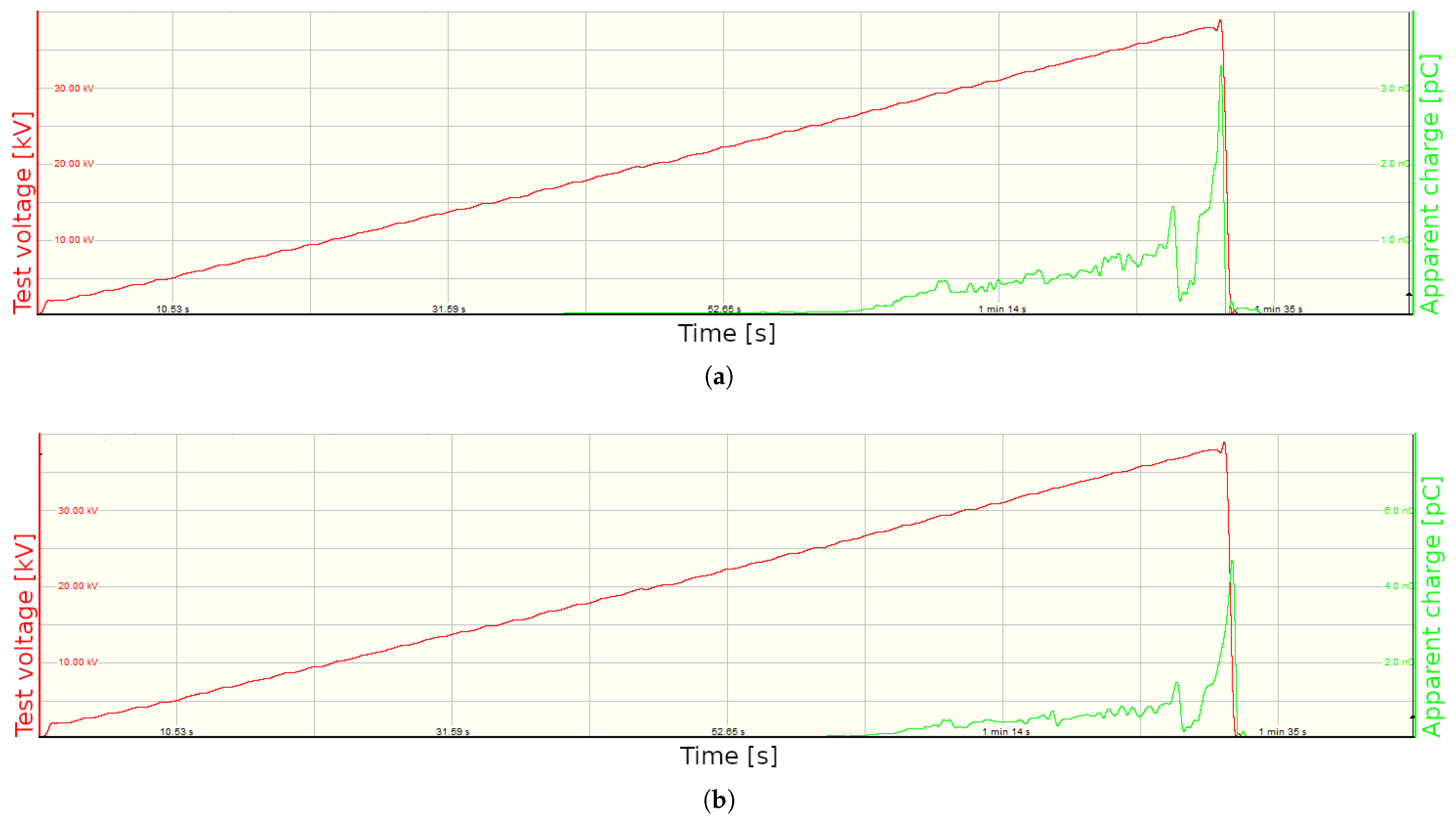
2.3. Measurement Methodology Adopted
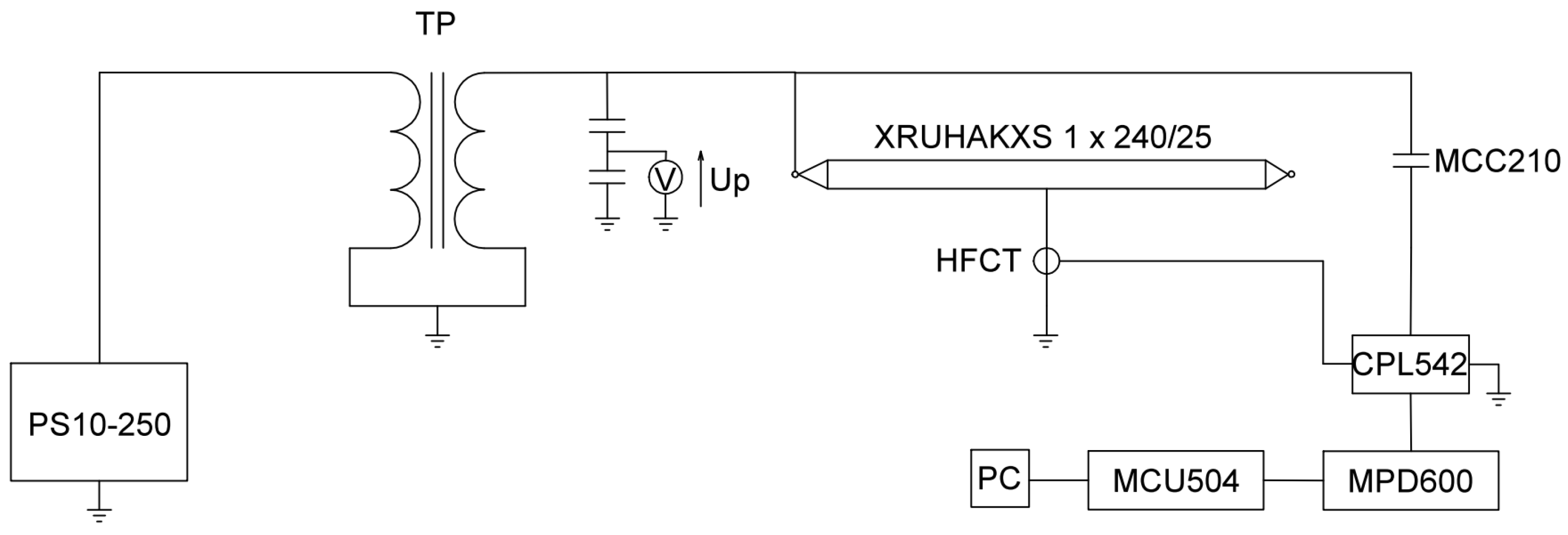
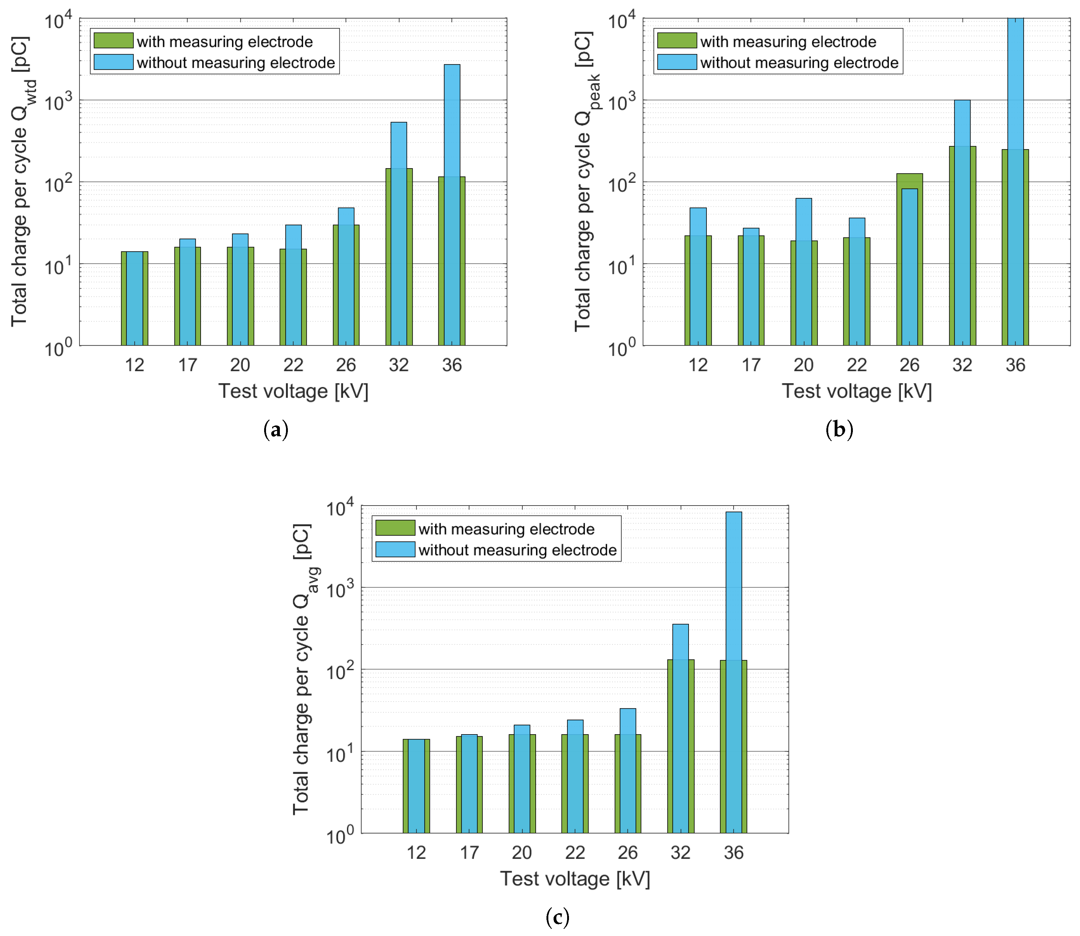
- Cable type XRUHAKXS 1 × 240/25, 12/20 kV with ends of cable terminations type 24-EPOT-1/70-240/(U) with installed corona rings,
- Cable type XRUHAKXS 1 × 240/25, 12/20 kV with cable terminations type 24-EPOT-1/70-240/(U) without installed corona rings.
- 1
- PS10-250 control panel,
- 2
- Capacitive voltage divider to measure the output voltage of the test transformer,
- 3
- TP test transformer with mains frequency Hz and voltage ratio = 0.22/110 ,
- 4
- Omicron MPD 600 PD analysis system, which includes:
- (a)
- PC,
- (b)
- MPD600 data acquisition unit,
- (c)
- MCU504 control unit,
- (d)
- CPL542 measuring impedance,
- (e)
- CAL542 charge calibrator,
- (f)
- MCC210 coupling capacitor,
- (g)
- HFCT coil type 991/21.
3. Results and Discussion
Results Analysis
4. Conclusions
Author Contributions
Funding
Institutional Review Board Statement
Informed Consent Statement
Data Availability Statement
Conflicts of Interest
References
- Hvidsten, S.; Holmgren, B.; Adeen, L.; Wetterstrom, J. Condition assessment of 12-and 24-kV XLPE cables installed during the 80s. Results from a joint Norwegian/Swedish research project. IEEE Electr. Insul. Mag. 2005, 21, 17–23. [Google Scholar] [CrossRef]
- Gulski, E.; Smit, J.J.; Wester, F.J. PD knowledge rules for insulation condition assessment of distribution power cables. IEEE Trans. Dielectr. Electr. Insul. 2005, 12, 223–239. [Google Scholar] [CrossRef]
- ElFaraskoury, A.; Mokhtar, M.; Mehanna, M.; Gouda, O. Conventional and un-conventional partial discharge detection methods in high voltage XLPE cable accessories. Adv. Electr. Eng. Syst. 2012, 1, 170–176. [Google Scholar]
- Götz, D.; Petzold, F.; Putter, H.; Markalous, S.; Stephan, M. Localized PRPD pattern for defect recognition on MV and HV cables. In Proceedings of the 2016 IEEE/PES Transmission and Distribution Conference and Exposition (T&D), Dallas, TX, USA, 3–5 May 2016; pp. 1–4. [Google Scholar]
- Álvarez Gómez, F.; Albarracín-Sánchez, R.; Garnacho Vecino, F.; Granizo Arrabé, R. Diagnosis of insulation condition of MV switchgears by application of different partial discharge measuring methods and sensors. Sensors 2018, 18, 720. [Google Scholar] [CrossRef] [Green Version]
- Chang, W.; Gong, Y.; Bi, J.; Ma, G.; Zhuang, Y. High frequency partial discharge measurement of straight power cable joint. In Proceedings of the 2017 IEEE Electrical Insulation Conference (EIC), Baltimore, MD, USA, 11–14 June 2017; pp. 229–232. [Google Scholar]
- Madonia, A.; Sanseverino, E.R.; Troia, I.; Bononi, S.F.; Giannini, S.; Mazzanti, G. Critical issues in the PD testing methodology for XLPE-insulated MV cables: An experimental case. In Proceedings of the 2017 IEEE Conference on Electrical Insulation and Dielectric Phenomenon (CEIDP), Fort Worth, TX, USA, 22–25 October 2017; pp. 311–314. [Google Scholar]
- Wang, Y.; Wang, Y.; Wang, C.; Xu, H. The partial discharge characteristic of typical XLPE cable insulation defects under damped oscillating voltage. In Proceedings of the 2014 IEEE Electrical Insulation Conference (EIC), Philadelphia, PA, USA, 8–11 June 2014; pp. 290–293. [Google Scholar]
- Hernandez-Mejia, J.C.; Harley, R.; Hampton, N.; Hartlein, R. Characterization of ageing for MV power cables using low frequency tan δ diagnostic measurements. IEEE Trans. Dielectr. Electr. Insul. 2009, 16, 862–870. [Google Scholar] [CrossRef]
- Figueroa Godoy, F.; Jimenez, J.T.; Vacio, R.J.; Yáñez Mendiola, J.; Colin, J.Á. Analysis of Insulating Material of XLPE Cables considering Innovative Patterns of Partial Discharges. Math. Probl. Eng. 2017, 2017, 2379418. [Google Scholar] [CrossRef]
- Mazzetti, C.; Mascioli, F.F.; Baldini, F.; Panella, M.; Risica, R.; Bartnikas, R. Partial discharge pattern recognition by neuro-fuzzy networks in heat-shrinkable joints and terminations of XLPE insulated distribution cables. IEEE Trans. Power Deliv. 2006, 21, 1035–1044. [Google Scholar] [CrossRef]
- Bragatto, T.; Cerretti, A.; D’Orazio, L.; Gatta, F.M.; Geri, A.; Maccioni, M. Thermal Effects of Ground Faults on MV Joints and Cables. Energies 2019, 12, 3496. [Google Scholar] [CrossRef] [Green Version]
- Bragatto, T.; Cresta, M.; Gatta, F.M.; Geri, A.; Maccioni, M.; Paulucci, M. Underground MV power cable joints: A nonlinear thermal circuit model and its experimental validation. Electr. Power Syst. Res. 2017, 149, 190–197. [Google Scholar] [CrossRef]
- Ghaderi, A.; Mingotti, A.; Peretto, L.; Tinarelli, R. Effects of Temperature on MV Cable Joints Tan Delta Measurements. IEEE Trans. Instrum. Meas. 2019, 68, 3892–3898. [Google Scholar] [CrossRef]
- Espín-Delgado, Á.; Letha, S.S.; Rönnberg, S.K.; Bollen, M.H.J. Failure of MV Cable Terminations Due to Supraharmonic Voltages: A Risk Indicator. IEEE Open J. Ind. Appl. 2020, 1, 42–51. [Google Scholar] [CrossRef]
- Park, H.D.; Kim, J.S.; Jeong, I.B.; Choi, K.J.; Ryu, B.H.; Hong, J.W. Defect diagnosis of the cable insulating materials by partial discharge statistical analysis. In Proceedings of the 2009 IEEE 9th International Conference on the Properties and Applications of Dielectric Materials, Harbin, China, 19–23 July 2009; pp. 293–296. [Google Scholar]
- Ahmed, Z.; Hussain, G.A.; Lehtonen, M.; Varacka, L.; Kudelcik, J. Analysis of partial discharge signals in medium voltage XLPE cables. In Proceedings of the 2016 IEEE 17th International Scientific Conference on Electric Power Engineering (EPE), Prague, Czech Republic, 16–18 May 2016; pp. 1–6. [Google Scholar]
- Lee, J.S.; Koo, J.Y.; Lim, Y.S.; Kim, J.T.; Lee, S.K. An analysis of the partial discharge pattern related to the artificial defects introduced at the interface in XLPE cable joint using laboratory model. In Proceedings of the Annual Report Conference on Electrical Insulation and Dielectric Phenomena, Cancun, Mexico, 20–24 October 2002; pp. 482–485. [Google Scholar]
- Jee Keen Raymond, W.; Illias, H.A.; Abu Bakar, A.H. Classification of partial discharge measured under different levels of noise contamination. PLoS ONE 2017, 12, e0170111. [Google Scholar] [CrossRef] [PubMed]
- Montanari, G.C. Partial discharge detection in medium voltage and high voltage cables: Maximum distance for detection, length of cable, and some answers. IEEE Electr. Insul. Mag. 2016, 32, 41–46. [Google Scholar] [CrossRef]
- Shafiq, M.; Kiitam, I.; Kauhaniemi, K.; Taklaja, P.; Kütt, L.; Palu, I. Performance comparison of PD data acquisition techniques for condition monitoring of medium voltage cables. Energies 2020, 13, 4272. [Google Scholar] [CrossRef]
- Zhu, Z.; Huang, C.; Yu, Y.; Zhang, M.; Qin, Y. Research on partial discharge mechanism and characteristics for 10kV cable joint with air gap defect. In Proceedings of the 2014 China International Conference on Electricity Distribution (CICED), Shenzhen, China, 23–26 September 2014; pp. 1246–1250. [Google Scholar]
- Ma, H.; Chan, J.C.; Saha, T.K.; Ekanayake, C. Pattern recognition techniques and their applications for automatic classification of artificial partial discharge sources. IEEE Trans. Dielectr. Electr. Insul. 2013, 20, 468–478. [Google Scholar] [CrossRef] [Green Version]
- Jiang, Y.; Min, H.; Luo, J.; Li, Y.; Li, H.; Jiang, X.; Xia, R.; Li, W. Partial discharge pattern Characteristic of MV Cable joints with artificial defect. In Proceedings of the IEEE CICED 2010 Proceedings, Chengdu, China, 28–31 March 2010; pp. 1–3. [Google Scholar]
- Singsathien, J.; Suwanasri, T.; Suwanasri, C.; Ruankon, S.; Fuangpian, P.; Namvong, W.; Saengsaikaew, P.; Khotsang, W. Partial discharge detection and localization of defected power cable using HFCT and UHF sensors. In Proceedings of the 2017 14th International Conference on Electrical Engineering/Electronics, Computer, Telecommunications and Information Technology (ECTI-CON), Phuket, Thailand, 27–30 June 2017; pp. 505–508. [Google Scholar]
- Raymond, W.J.K.; Illias, H.A. High noise tolerance feature extraction for partial discharge classification in XLPE cable joints. IEEE Trans. Dielectr. Electr. Insul. 2017, 24, 66–74. [Google Scholar] [CrossRef]
- Götz, D.; Putter, H.T. UHF pd-diagnosis at high voltage cable terminations—International case studies. In Proceedings of the 2017 IEEE INSUCON-13th International Electrical Insulation Conference (INSUCON), Birmingham, UK, 16–18 May 2017; pp. 1–5. [Google Scholar]
- Abdullah, A.Z.; Rohani, M.N.K.H.; Isa, M.; Hamid, H.; Arshad, S.N.M.; Othman, M. Real On-Site Partial Discharge Measurement Technique in Medium Voltage Power Cable. In Proceedings of the 2018 IEEE 7th International Conference on Power and Energy (PECon), Kuala Lumpur, Malaysia, 3–4 December 2018; pp. 405–408. [Google Scholar]
- Shafiq, M.; Kauhaniemi, K.; Robles, G.; Isa, M.; Kumpulainen, L. Online condition monitoring of MV cable feeders using Rogowski coil sensors for PD measurements. Electr. Power Syst. Res. 2019, 167, 150–162. [Google Scholar] [CrossRef]
- Álvarez, F.; Garnacho, F.; Ortego, J.; Sánchez-Urán, M.Á. Application of HFCT and UHF sensors in on-line partial discharge measurements for insulation diagnosis of high voltage equipment. Sensors 2015, 15, 7360–7387. [Google Scholar] [CrossRef] [Green Version]
- Milioudis, A.; Andreou, G.; Labridis, D. On-line partial discharge monitoring system for underground MV cables–Part II: Detection and location. Int. J. Electr. Power Energy Syst. 2019, 109, 395–402. [Google Scholar] [CrossRef]
- Zhao, X.; Pu, L.; Ju, Z.; Ren, S.; Duan, W.; Wang, J. Partial discharge characteristics and development of typical XLPE power cable insulation defects. In Proceedings of the IEEE 2016 International Conference on Condition Monitoring and Diagnosis (CMD), Xi’an, China, 25–28 September 2016; pp. 623–626. [Google Scholar]
- Wang, X.; Wang, C.C.; Wu, K.; Tu, D.M.; Liu, S.; Peng, J.K. An improved optimal design scheme for high voltage cable accessories. IEEE Trans. Dielectr. Electr. Insul. 2014, 21, 5–15. [Google Scholar] [CrossRef]
- Metwally, I.A.; Al-Badi, A.H.; Al-Hinai, A.S.; Al Kamali, F.; Al-Ghaithi, H. Influence of design parameters and defects on electric field distributions inside MV cable joints. In Proceedings of the 2016 18th Mediterranean Electrotechnical Conference (MELECON), Lemesos, Cyprus, 18–20 April 2016; pp. 1–6. [Google Scholar]
- Wang, L.; Cavallini, A.; Montanari, G.C. Time behavior of gas pressure and PD activity in insulation cavities under AC voltage. In Proceedings of the 2010 Annual Report Conference on Electrical Insulation and Dielectic Phenomena, West Lafayette, IN, USA, 17–20 October 2010; pp. 1–4. [Google Scholar]
- Illias, H.; Chen, G.; Lewin, P.L. Partial discharge behavior within a spherical cavity in a solid dielectric material as a function of frequency and amplitude of the applied voltage. IEEE Trans. Dielectr. Electr. Insul. 2011, 18, 432–443. [Google Scholar] [CrossRef]


| Item Number | Item Type | Elements View |
|---|---|---|
| 1 | Screw tip | 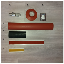 |
| 2 | Heat-shrinkable cover CES-02 | |
| 3 | Electrically insulating grease | |
| 4 | Insulating pipe RART 49/16-450 | |
| 5 | RSCT 47/14-160 control tube | |
| 6 | EP MASTIK 30 mastic | |
| 7 | EP STRESS 20 control strap |
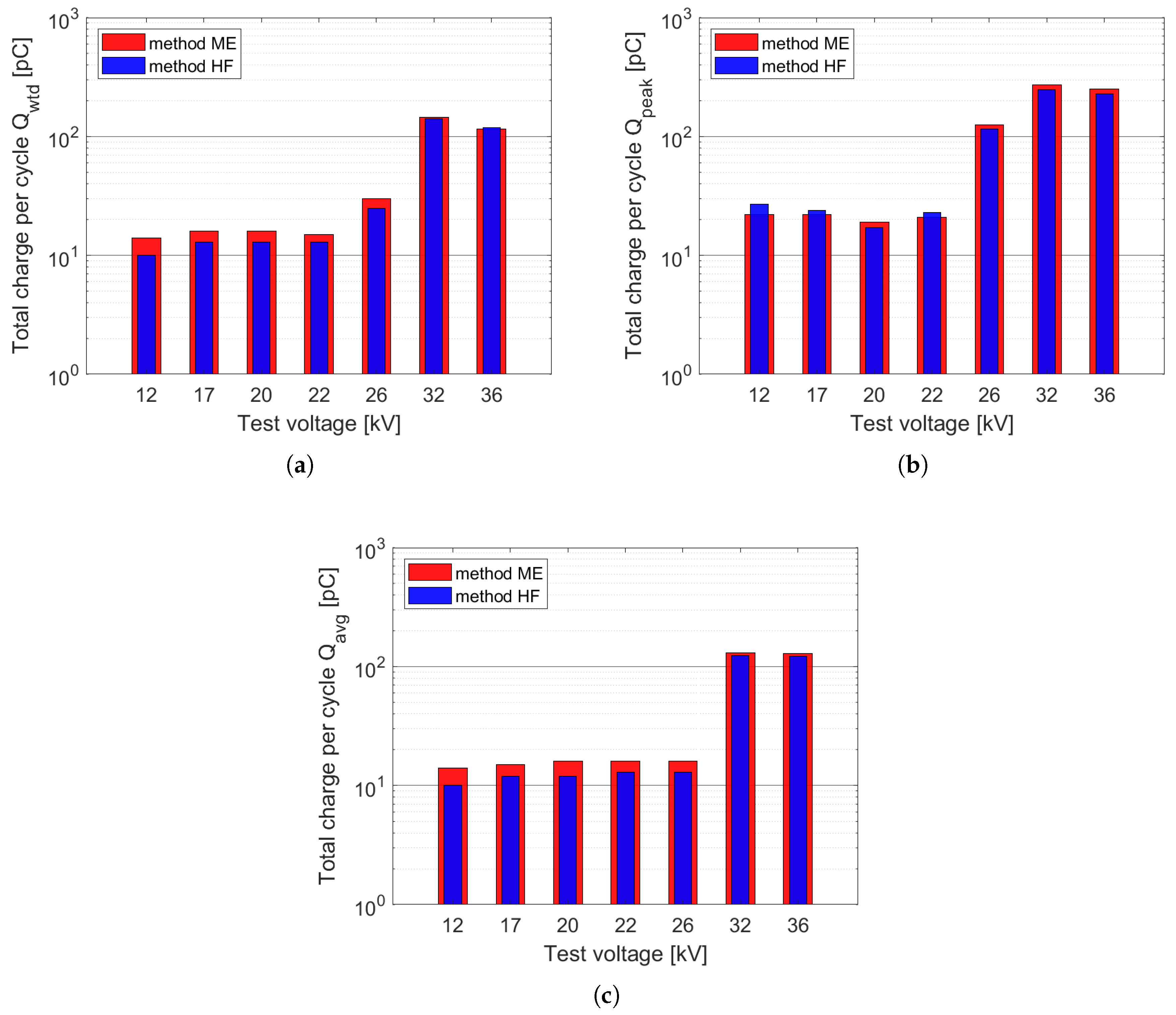
| Test Voltage | ME Method | HF Method | ||||
|---|---|---|---|---|---|---|
| [kV] | [pC] | [pC] | [pC] | [pC] | [pC] | [pC] |
| 12 | 14 | 22 | 14 | 10 | 27 | 10 |
| 17 | 16 | 22 | 15 | 13 | 24 | 12 |
| 20 | 16 | 19 | 16 | 13 | 17 | 12 |
| 22 | 15 | 21 | 16 | 13 | 23 | 13 |
| 26 | 30 | 125 | 16 | 25 | 115 | 13 |
| 32 | 145 | 270 | 130 | 142 | 249 | 123 |
| 36 | 115 | 250 | 129 | 119 | 229 | 122 |
| Test Voltage | With Measuring Electrode | Without Measuring Electrode |
|---|---|---|
| 20 kV | 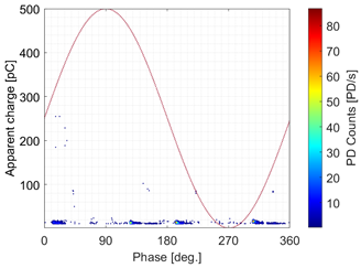 | 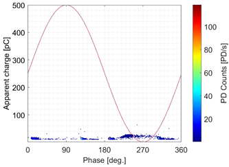 |
| 22 kV | 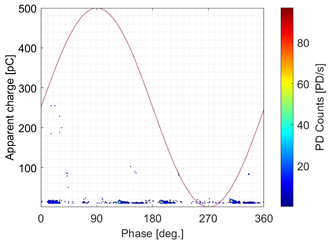 | 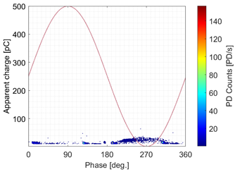 |
| 26 kV | 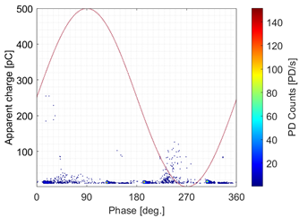 | 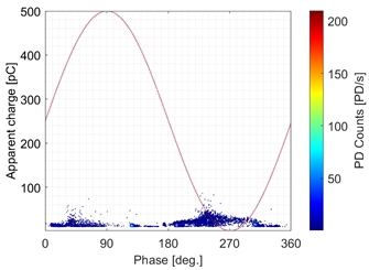 |
| 32 kV |  | 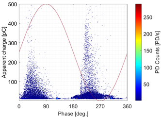 |
| 36 kV | 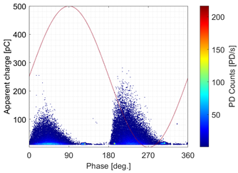 |  |
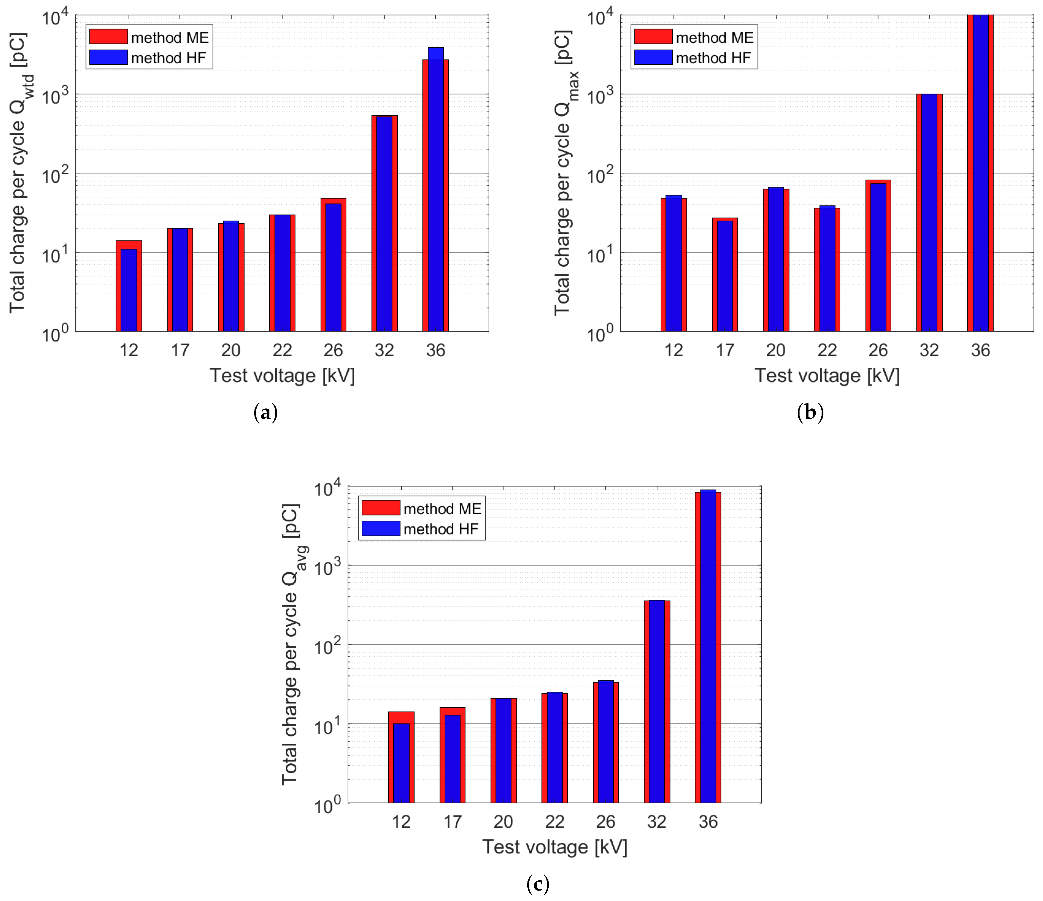
| Test Voltage | ME Method | HF Method | ||||
|---|---|---|---|---|---|---|
| [kV] | [pC] | [pC] | [pC] | [pC] | [pC] | [pC] |
| 12 | 14 | 48 | 14 | 11 | 53 | 10 |
| 17 | 20 | 27 | 16 | 20 | 25 | 13 |
| 20 | 23 | 63 | 21 | 25 | 66 | 21 |
| 22 | 30 | 36 | 24 | 30 | 39 | 25 |
| 26 | 48 | 82 | 33 | 41 | 74 | 35 |
| 32 | 537 | 989 | 353 | 514 | 1000 | 360 |
| 36 | 2707 | 136,700 | 8286 | 3831 | 112,400 | 8957 |
| Test Voltage | With Measuring Electrode | Without Measuring Electrode |
|---|---|---|
| 20 kV | 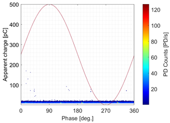 |  |
| 22 kV |  | 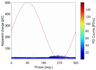 |
| 26 kV | 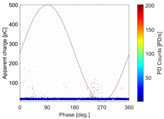 | 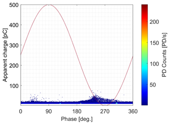 |
| 32 kV | 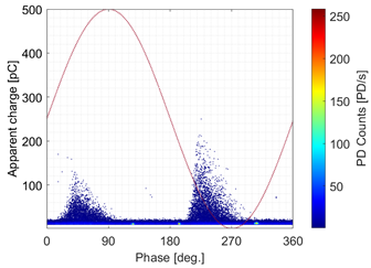 |  |
| 36 kV | 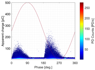 |  |
Publisher’s Note: MDPI stays neutral with regard to jurisdictional claims in published maps and institutional affiliations. |
© 2022 by the authors. Licensee MDPI, Basel, Switzerland. This article is an open access article distributed under the terms and conditions of the Creative Commons Attribution (CC BY) license (https://creativecommons.org/licenses/by/4.0/).
Share and Cite
Rybarz, J.; Borucki, S.; Kunicki, M.; Kucińska-Landwójtowicz, A.; Wajnert, D. Influence of the Cable Accessories Installing Method on the Partial Discharge Activity in Medium Voltage Cables. Energies 2022, 15, 4216. https://doi.org/10.3390/en15124216
Rybarz J, Borucki S, Kunicki M, Kucińska-Landwójtowicz A, Wajnert D. Influence of the Cable Accessories Installing Method on the Partial Discharge Activity in Medium Voltage Cables. Energies. 2022; 15(12):4216. https://doi.org/10.3390/en15124216
Chicago/Turabian StyleRybarz, Jacek, Sebastian Borucki, Michał Kunicki, Aneta Kucińska-Landwójtowicz, and Dawid Wajnert. 2022. "Influence of the Cable Accessories Installing Method on the Partial Discharge Activity in Medium Voltage Cables" Energies 15, no. 12: 4216. https://doi.org/10.3390/en15124216