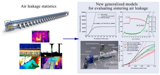
Mathematical Modeling of Sintering Air Leakage through Holes
Abstract
:1. Introduction
2. Description of Simplified Model of Sintering System
2.1. System Description
- (1)
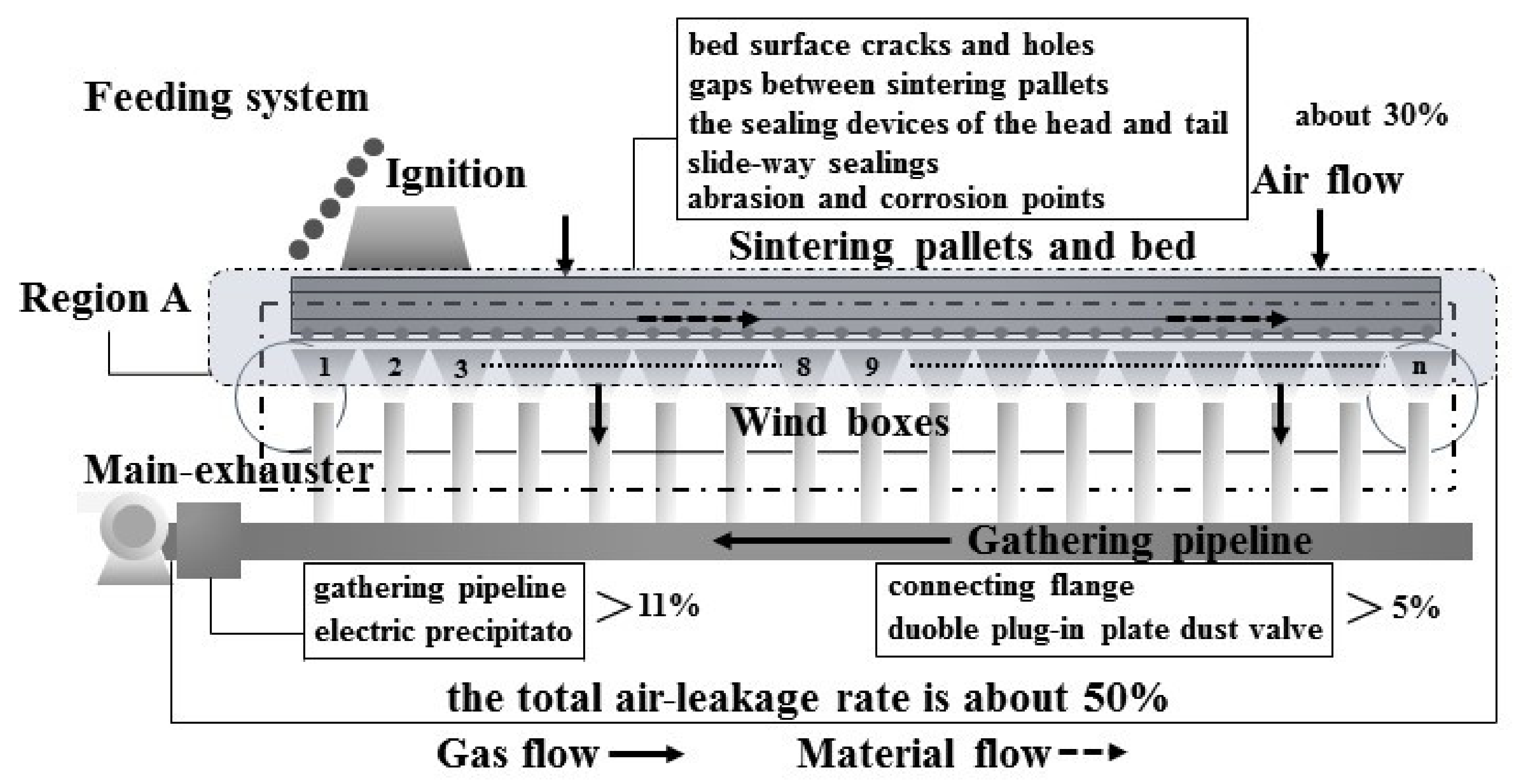
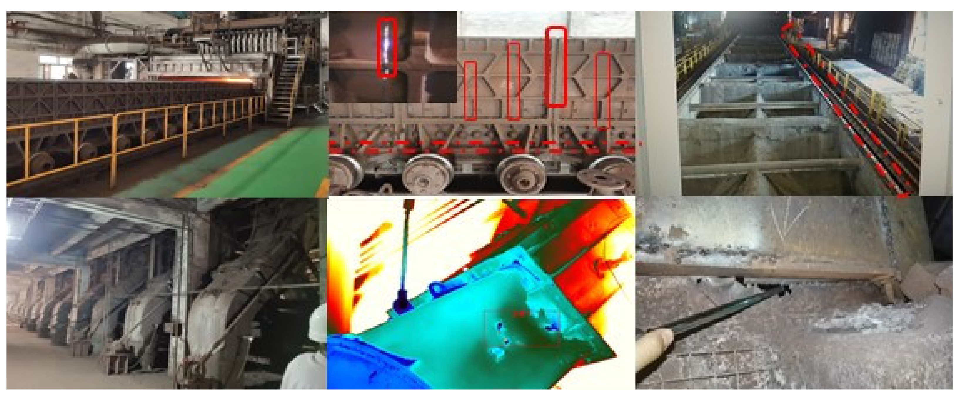
- All leakage points (cf. Figure 3a) occurring in region A are equivalent to one hole for convenience;
- (2)
- The sintering process is steady, so the thermal state of each wind box is stable;
- (3)
- The cross-section area of wind boxes is tapered along the vertical direction (cf. Figure 3a). It is reasonable to treat Region A with the same equivalent diameter;
- (4)
- Because the packed bed has a vast interfacial area, its frictional loss is usually much greater than that of the rest of the sintering system. Therefore, the local and on-way resistance inside region A can be ignored;
- (5)
- The absolute pressure variation is usually less than 10% in the sintering bed. The working temperature along the length of the sintering machine varies greatly. Thus, the state equation for the incompressible ideal gas is used for the study (cf. Equation (1)). It can convert the different isothermal beds of each wind box position into the same temperature state.
2.2. Main Equations of the Simplified Model
2.3. Hole Model
2.4. Counter-Flow Bed Model
2.5. Hole–Bed Model
3. Application Example of Models
3.1. Hole Model Results
3.2. Counter-Flow Bed Model Results
3.3. Hole–Bed Model Results
3.3.1. Discussion of Flow and Pressure Results
3.3.2. Discussion of Different Process Parameters
4. Model Validations and Flow Coefficient
4.1. Bed Model Validation
4.2. Hole Model Validation
4.3. Hole–Bed Model Validation
5. Conclusions
- (1)
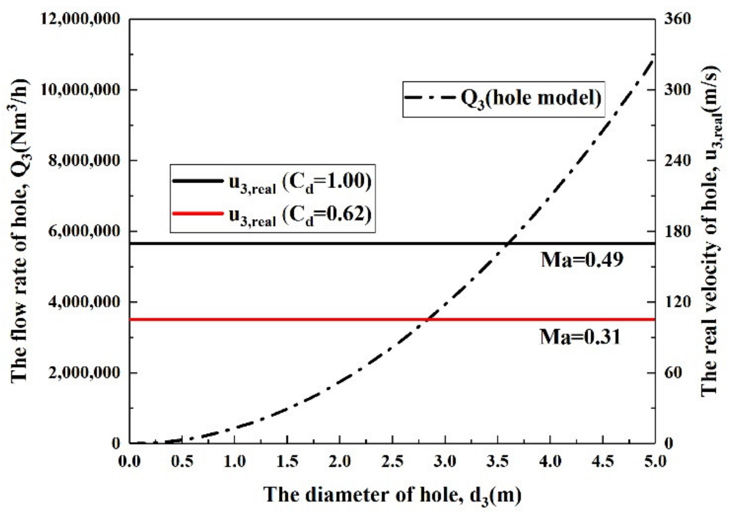
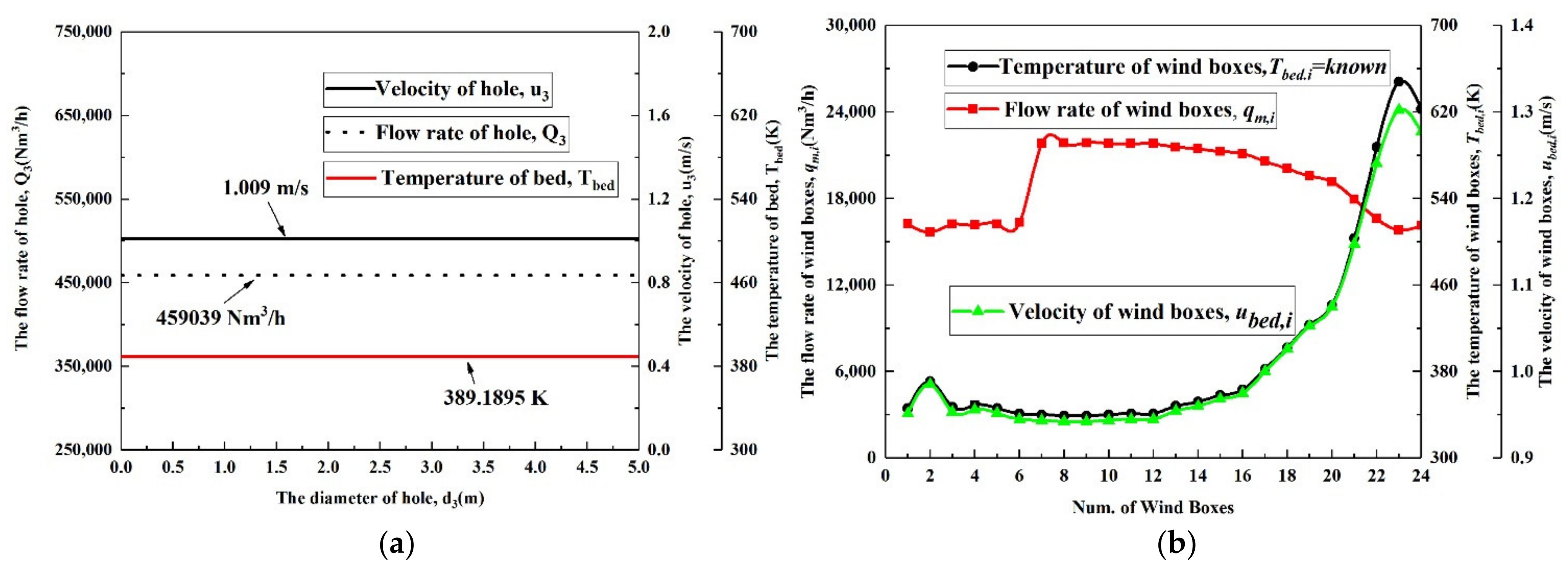
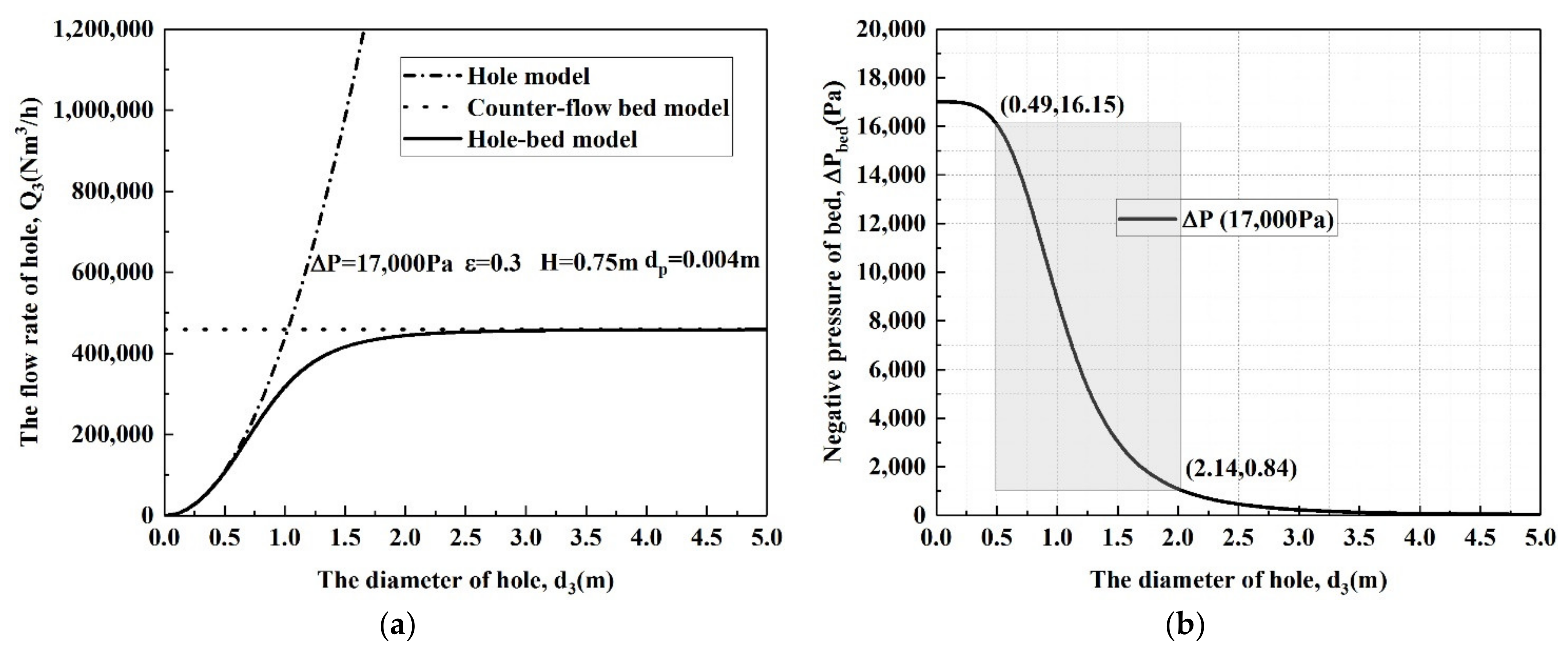
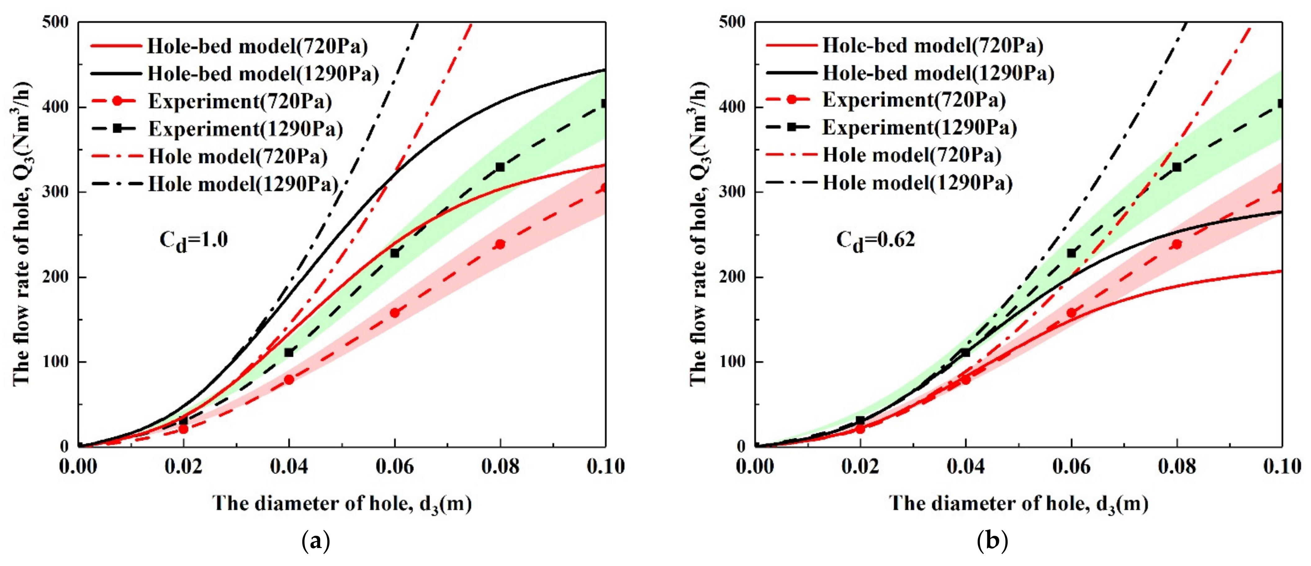
- The hole model conforms to the basic principle of constant orifice outflow. The hole model can predict the leakage flow rate when the hole is small. The counter-flow bed model can be used in a complete breaking. Although this case does not exist, it can estimate the flow rate of the total airflow; while the hole lies between the above two situations, the hole–bed model can be used;
- (2)
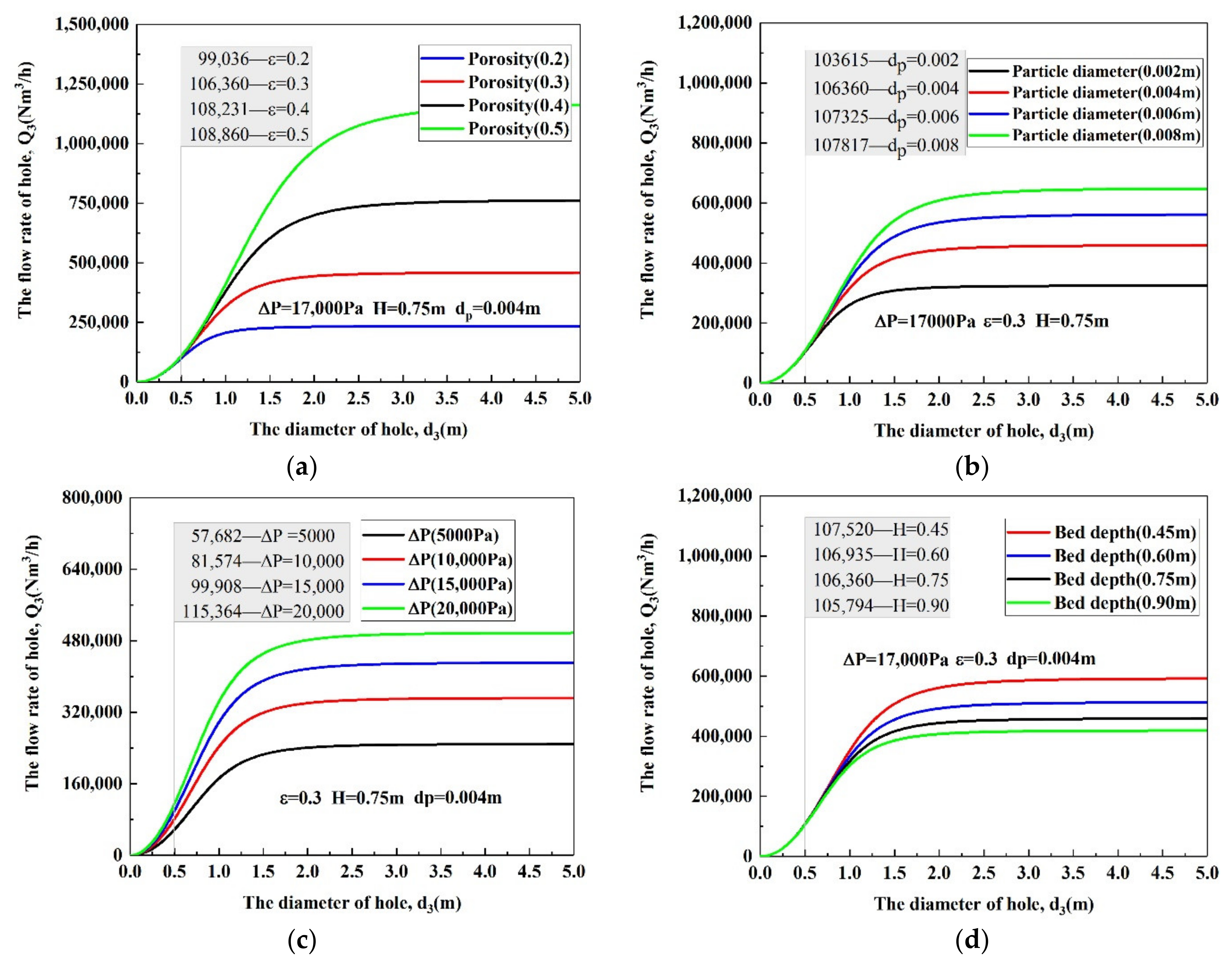
- The hole bed model combines the characteristics of the other two models. The leakage is preliminarily combined with the sintering process through the bed equation. In this case, the model also allows the calculation of the decrease in pressure over the sintering bed. The pressure of the sintering bed is affected by leakage parameters;
- (3)
- The calculation results show that the leakage flow rate of any hole is calculated and mastered at one time entirely in a steady process. It effectively reduces testing time, energy consumption and air leakage detection costs. With the model, real-time local leakage detection and a fast estimation system could be possible in the future and improve the detection means in the key area;
- (4)
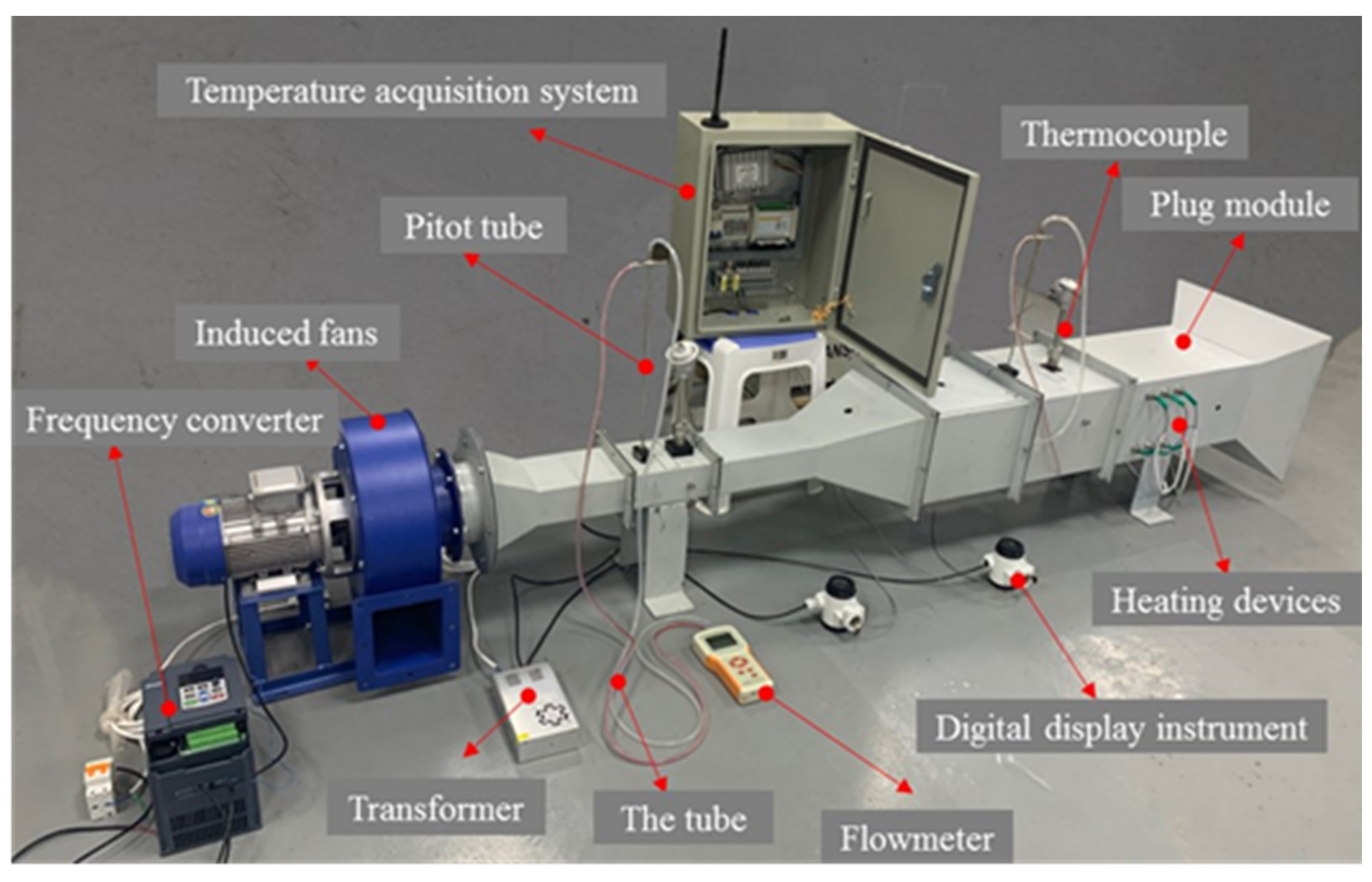
- Experiment results prove the validation of the models and give the flow coefficient for preliminary application. The flow coefficient can reduce the uncertainty of the estimation of air leakage.
Author Contributions
Funding
Institutional Review Board Statement
Informed Consent Statement
Data Availability Statement
Conflicts of Interest
Abbreviations
| Abed | The area of the sintering bed, (m2) |
| Abed,i | The area of the sintering bed at each wind box location, (m2) |
| A1 | The area of cross-section 1, (m2) |
| A2 | The area of cross-section 2, (m2) |
| A3 | The leakage hole area, (m2) |
| Cd | The flow coefficient |
| De | The equivalent diameter of the sintering bed, (m) |
| dp | The particle size, (m) |
| d3 | The equivalent diameter of the hole, (m) |
| ET | The estimation deviation between different temperature locations |
| Em | The estimation deviation between the hole and hole–bed models |
| EQ | The estimation deviation under different processes |
| Ftotal | The total friction. |
| Fpacked | The frictional loss of packed beds. |
| H | The bed height, (m) |
| i | The number of wind boxes |
| M | The molecular weight of the air, (kg/kmol) |
| Ma | Mach number |
| n | The total amount of wind boxes. |
| Pa | The ambient environment pressure, (Pa) |
| P1 | The absolute pressure of cross-section 1, (Pa) |
| P2 | The absolute pressure of cross-section 2, (Pa) |
| P3 | The absolute pressure of the hole, (Pa) |
| P1,i | The absolute pressure of cross-section 1 at each wind box location, (Pa) |
| P2,i | The absolute pressure of cross-section 2 at each wind box location, (Pa) |
| Pbed,i | The absolute pressure at each wind box location, (Pa) |
| ΔPbed | The negative pressure of the sintering bed, (Pa) |
| ΔPbed,i | The negative pressure of each wind box location, (Pa) |
| qm,i | The flow rate through the sintering bed at each wind box location, (kg/s) |
| Q3 | The leakage flow rate of the hole, (kg/s) |
| Qm | The flow rate of the sintering system(Region A), (kg/s) |
| Q3,hole | The leakage flow rate calculated by the hole model in Figure 7, (Nm3/h) |
| Q3,hole-bed | The leakage flow rate calculated by the hole–bed model in Figure 7, (Nm3/h) |
| Q3,based | The based flow rate in the hole–bed model in Figure 7, (Nm3/h) |
| Q3,other | The flow rate under other processes in Figure 8, (Nm3/h) |
| Q3,mea | The measured value of the leakage flow rate, (Nm3/h) |
| R | The constant of gas, (J/kmol·K) |
| Ta | The ambient environment temperature, (K) |
| T1 | The temperature of cross-section 1, (K) |
| T2 | The temperature of cross-section 2, (K) |
| T1,i | The temperature of cross-section 1 at each wind box location, (K) |
| T2,i | The temperature of cross-section 2 at each wind box location, (K) |
| Tbed | The mixed temperature of the whole sintering bed, (K) |
| Tbed,i | The temperature at each wind box location, (K) |
| u | The velocity, (m/s) |
| ρ | The density, (kg/m3) |
| ρbed,i | The density of the sintering bed at each wind box location, (kg/m3) |
| ρ1,i | The density of cross-section 1 at each wind box location, (kg/m3) |
| ρ2,i | The density of cross-section 2 at each wind box location, (kg/m3) |
| u1,i | The velocity of cross-section 1 at each wind box location, m/s |
| u2,i | The velocity of cross-section 2 at each wind box location, m/s |
| ubed,i | The velocity of the sintering bed at each wind box location, m/s |
| μ | The air viscosity, (kg/m/s) |
| ε | The bed porosity. |
| ζ3 | The local resistance coefficient of the hole. |
| HMI | Human Machine Interface |
| Known | The known values in sintering plants. |
| EGIG | European Gas Pipeline Incident Data Group |
References
- Wang, Y.Z.; Zhang, J.L.; Liu, Z.J.; Du, C.B. Recent Advances and Research Status in Energy Conservation of Iron Ore Sintering in China. JOM 2017, 69, 2404–2411. [Google Scholar] [CrossRef]
- Fan, X.H.; Jiang, L.J.; Chen, X.L. Air Leakage Online Monitoring and Diagnosis Model for Sintering. In Proceedings of the 3rd International Symposium on High-Temperature Metallurgical Processing, TMS (The Minerals, Metals & Materials Society), Orlando, FL, USA, 11–15 March 2012; pp. 323–329. [Google Scholar]
- Song, X.Y.; Li, W.H. On the Air Leakage Rate Measurement Technology of Sintering Machine System. Energy Energy Conserv. 2013, 95, 51–53. (In Chinese) [Google Scholar]
- Jin, Y.L.; Xu, N.P.; Wu, S.Y.; Cheng, Z.F. Study and Application of a New Technology for Measuringthe Leakage Ratio of Sintering Machine. J. Iron Steel Res. 1999, 11, 67–70. (In Chinese) [Google Scholar]
- Sakaue, H. Improvement of Production by Decreasing Air Leak at Nagoya No. 3 Sintering Plant. Tetsu-to-Hagane-J. Iron Steel Inst. Jpn. 2009, 95, 582–585. (In Japanese) [Google Scholar] [CrossRef]
- Shiau, J.S.; Huang, T.Y.; Liu, S.H.; Hsieh, C.M.; Yeh, P.Y. Energy Saving Technology for Lowering Air Leakage of Sintering Pallets and Dust Collectors in Sinter Plant. J. Mech. Eng. Autom. 2018, 8, 233–249. [Google Scholar]
- Woodard, J.L.; Mudan, K.S. Liquid and gas discharge rates through holes in process vessels. J. Loss Prev. Process Ind. 1991, 4, 161–165. [Google Scholar] [CrossRef]
- Crowl, D.A.; Louvar, J.F. Chemical Process Safety: Fundamentals with Application, 3rd ed.; Pearson: Upper Saddle River, NJ, USA, 2012; pp. 122–146. [Google Scholar]
- Turton, R. A new approach to non-choking adiabatic compressible flow of an ideal gas m pipes with friction. Chem. Eng. J. 1985, 30, 159–160. [Google Scholar] [CrossRef]
- Levinspiel, O. Engineering Flow and Heat Exchange, 3rd ed.; Springer: New York, NY, USA, 2014; pp. 20–51. [Google Scholar]
- Montiel, H.; Vilchez, J.A.; CasaL, J.; Arnaldos, J. Mathematical modelling of accidental gas releases. J. Hazard. Mater. 1998, 59, 211–233. [Google Scholar] [CrossRef]
- Arnaldos, J.; Casal, J.; Montiel, H.; Sánchez-Carricondo, M.; Vílchez, J.A. Design of a computer tool for the evaluation of the consequences of accidental natural gas releases in distribution pipes. J. Loss Prev. Process Ind. 1998, 11, 135–148. [Google Scholar] [CrossRef]
- Hankinson, G.; Lowesmith, B.J.; Genillon, P.; Hamaide, G. Experimental Studies of Releases of High Pressure Natural Gas from Punctures and Rips in Above-Ground Pipework. In Proceedings of the 3rd International Pipeline Conference (IPC2000), Calgary, AB, Canada, 1–5 October 2000. [Google Scholar]
- Picard, D.J.; Bishnoi, P.R. The importance of real-fluid behavior in predicting release rates resulting from high-pressure sour-gas pipeline ruptures. Can. J. Chem. Eng. 1989, 67, 3–9. [Google Scholar] [CrossRef]
- Dong, Y.H.; Gao, H.L.; Zhou, J.E.; Feng, Y.R. Evaluation of gas release rate through holes in pipelines. J. Loss Prev. Process Ind. 2002, 15, 423–428. [Google Scholar]
- Dong, Y.H.; Gao, H.L.; Zhou, J.E.; Feng, Y.R. Mathematical modeling of gas release through holes in pipelines. Chem. Eng. J. 2003, 92, 237–241. [Google Scholar]
- Mahgertfteh, H.; Saha, P.; Economou, I.G. A Study of the Dynamic Response of Emergency Shutdown Valves Following Full Bore Rupture of Gas Pipelines. Process Saf. Environ. Protect. 1997, 75, 201–209. [Google Scholar] [CrossRef] [Green Version]
- Mahgertfteh, H.; Saha, P.; Economou, I.G. Fast numerical simulation for full bore rupture of pressurized pipelines. AICHE J. 1999, 45, 1191–1201. [Google Scholar] [CrossRef]
- Mahgertfteh, H.; Oke, A.; Atti, O. Modelling outflow following rupture in pipeline networks. Chem. Eng. Sci. 2006, 16, 1811–1818. [Google Scholar] [CrossRef]
- Jo, Y.D.; Ahn, B.J. A simple model for the release rate of hazardous gas from a hole on high-pressure pipelines. J. Hazard. Mater. 2003, 97, 31–46. [Google Scholar] [CrossRef]
- Jo, Y.D.; Ahn, B.J. Analysis of hazard area associated with hydrogen gas transmission pipelines. Int. J. Hydrog. Energy 2006, 31, 2122–2130. [Google Scholar] [CrossRef]
- Jo, Y.D.; Crowl, D.A. Individual risk analysis of high-pressure natural gas pipelines. J. Loss Prev. Process Ind. 2008, 21, 589–595. [Google Scholar] [CrossRef]
- Kostowski, W.J.; Skorek, J. Application of experimental flow characteristics of pipeline ruptures in gas network simulation. Inz. Chem. Proces 2006, 27, 579–596. [Google Scholar]
- Kostowski, W.J.; Skorek, J. Real gas flow simulation in damaged distribution pipelines. Energy 2012, 45, 481–488. [Google Scholar] [CrossRef]
- He, G.X.; Lyu, X.D.; Liao, K.X.; Li, Y.S.; Sun, L.Y. A method for fast simulating the liquid seepage-diffusion process coupled with internal flow after leaking from buried pipelines. J. Clean. Prod. 2019, 240, 118167. [Google Scholar] [CrossRef]
- Ebrahimi-Moghadam, A.; Farzaneh-Gord, M.; Deymi-Dashtebayaz, M. Correlations for estimating natural gas leakage from above-ground and buried urban distribution pipelines. J. Nat. Gas Sci. Eng. 2016, 34, 185–196. [Google Scholar] [CrossRef]
- Ebrahimi-Moghadam, A.; Farzaneh-Gord, M.; Arabkoohsar, A.; Jabari-Moghadam, A. CFD analysis of natural gas emission from damaged pipelines: Correlation development for leakage estimation. J. Clean. Prod. 2018, 199, 257–271. [Google Scholar] [CrossRef]
- Farzaneh-Gord, M.; Pahlevan-Zadeh, M.S.; Ebrahimi-Moghadam, A.; Rastgar, S. Measurement of methane emission into environment during natural gas purging process. J. Environ. Pollut. 2018, 242, 2014–2026. [Google Scholar] [CrossRef] [PubMed]
- Li, X.H.; Chen, G.M.; Zhang, R.R.; Zhu, H.W.; Fu, J.M. Simulation and assessment of underwater gas release and dispersion from subsea gas pipelines leak. Process Saf. Environ. Protect. 2018, 119, 46–57. [Google Scholar]
- Fiates, J.; Santos, R.R.C.; Neto, F.F.; Francesconi, A.Z.; Simoes, V.; Vianna, S.S.V. An alternative CFD tool for gas dispersion modelling of heavy gas. J. Loss Prev. Process Ind. 2016, 44, 583–593. [Google Scholar] [CrossRef]
- Huseynov, J.; Baliga, S.; Dillencourt, M.; Bic, L.; Bagherzadeh, N. Gas-leak localization using distributed ultrasonic sensors. In Proceedings of the SPIE 7293, San Diego, CA, USA, 8–12 March 2009; Volume 7293. [Google Scholar]
- Dudić, S.; Ignjatović, I.; Šešlija, D.; Blagojevićand, V.; Stojiljković, M. Leakage quantification of compressed air using ultrasound and infrared thermography. Measurement 2012, 45, 1689–1694. [Google Scholar] [CrossRef]
- Liu, C.W.; Li, Y.X.; Fang, L.P.; Xu, M.H. New leak-localization approaches for gas pipelines using acoustic waves. Measurement 2019, 134, 54–65. [Google Scholar] [CrossRef]
- Wang, S.; Yao, X.F. Aeroacoustics measurement of the gas leakage rate for single hole. Rev. Sci. Instrum. 2020, 91, 045102. [Google Scholar] [CrossRef]
- Mostafapour, A.; Davoudi, S. Analysis of leakage in high pressure pipe using acoustic emission method. Appl. Acoust. 2013, 74, 335–342. [Google Scholar] [CrossRef]
- Jin, H.; Zhang, L.B.; Liang, W.; Ding, Q.K. Integrated leakage detection and localization model for gas pipelines based on the acoustic wave method. J. Loss Prev. Process Ind. 2014, 27, 74–88. [Google Scholar] [CrossRef]
- Li, J.K.; Jin, W.Q.; Wang, X.; Zhang, X. MRGC performance evaluation model of gas leak infrared imaging detection system. Opt. Express 2014, 22, A1701–A1712. [Google Scholar] [CrossRef]
- Wang, S.; Yao, X.F.; Yang, H. The heat conduction model and leakage characterization of the sealing interface. Int. J. Therm. Sci. 2019, 145, 106027. [Google Scholar] [CrossRef]
- Yang, H.; Yao, X.F.; Wang, S.; Yuan, L.; Ke, Y.C.; Liu, Y.H. Simultaneous determination of gas leakage location and leakage rate based on local temperature gradient. Measurement 2019, 133, 233–240. [Google Scholar] [CrossRef]
- Wang, S.; Yao, X.F.; Yang, H.; Yuan, L.; Dong, Y.F. A new leakage measurement method for damaged seal material. Meas. Sci. Technol. 2018, 29, 075203. [Google Scholar] [CrossRef]
- Ergun, S. Fluid flow through packed columns. Chem. Eng. Prog. 1952, 48, 89–94. [Google Scholar]
- Hinkley, J.; Waters, A.G.; Litster, J.D. An investigation of pre-ignition air flow in ferrous sintering. Int. J. Miner. Process. 1994, 42, 37–52. [Google Scholar] [CrossRef]
- Wang, G.; Wen, Z.; Lou, G.F.; Dou, R.F.; Li, X.W.; Liu, X.L.; Su, F.Y. Mathematical modeling and combustion characteristic evaluation of a flue gas recirculation iron ore sintering process. Int. J. Heat Mass Transf. 2016, 97, 964–974. [Google Scholar] [CrossRef]
- Brower, W.B.; Eisler, E.; Filkorn, E.J.; Gonenc, J.; Plati, C.; Stagnitti, J. On the Compressible Flow Through an Orifice. J. Fluids Eng.-Trans. ASME 1993, 115, 660–664. [Google Scholar] [CrossRef]
- Szente, V.; Vad, J. A semi-empirical model for characterisation of flow coefficient for pneumatic solenoid valves. Period. Polytech-Mech. Eng. 2003, 47, 131–142. [Google Scholar]


| Item | Parameters | Unit | Value |
|---|---|---|---|
| Sintering area of oneside | Abed | m2 | 180 |
| Area of the sintering bed at each wind box location | Abed,i (i = 1~6) Abed,i (i = 7~24) | m2 m2 | 3 × 2 4 × 2 |
| Bed height | H | m | 0.75 |
| Bed porosity | ε | 0.3 | |
| Molecular weight of the air | M | kg/kmol | 29 |
| Constant of gas | R | J/kmol·K | 8314 |
| Particle size | dp | m | 0.004 |
| Number of wind boxes | n | group | 24 |
| Ambient environment temperature | Ta | K | 300 |
| Ambient environment pressure | Pa | Pa | 101,325 |
| Pressure of the sintering bed | Pbed | Pa | 84,325 |
| Negative pressure of gathering pipeline | ΔPbed | Pa | 17,000 |
| Temperature of gathering pipeline | Tbed | K | 390~470 |
| Num. of Wind Boxes | Tbed,i = Known (K) | Pbed,i = Known (Pa) | ΔPbed,i = Known (Pa) | qm,i Solved (Nm3/h) |
|---|---|---|---|---|
| 1 | 345.99 | 84,325 | 17,000 | 16,228.62311 |
| 2 | 370.87 | 84,325 | 17,000 | 15,674.8212 |
| 3 | 347.15 | 84,325 | 17,000 | 16,201.48649 |
| 4 | 349.15 | 84,325 | 17,000 | 16,155.01719 |
| 5 | 346.15 | 84,325 | 17,000 | 16,224.87202 |
| 6 | 341.15 | 84,325 | 17,000 | 16,343.3379 |
| 7 | 340.15 | 84,325 | 17,000 | 21,823.12532 |
| 8 | 339.15 | 84,325 | 17,000 | 21,855.27491 |
| 9 | 339.15 | 84,325 | 17,000 | 21,855.27491 |
| 10 | 340.15 | 84,325 | 17,000 | 21,823.12532 |
| 11 | 341.15 | 84,325 | 17,000 | 21,791.1172 |
| 12 | 341.15 | 84,325 | 17,000 | 21,791.1172 |
| 13 | 348.15 | 84,325 | 17,000 | 21,570.93572 |
| 14 | 352.15 | 84,325 | 17,000 | 21,448.07591 |
| 15 | 358.15 | 84,325 | 17,000 | 21,267.65989 |
| 16 | 363.15 | 84,325 | 17,000 | 21,120.74145 |
| 17 | 382.15 | 84,325 | 17,000 | 20,588.99994 |
| 18 | 402.15 | 84,325 | 17,000 | 20,070.49797 |
| 19 | 423.15 | 84,325 | 17,000 | 19,566.13347 |
| 20 | 441.47 | 84,325 | 17,000 | 19,155.85699 |
| 21 | 503.15 | 84,325 | 17,000 | 17,943.34659 |
| 22 | 587.65 | 84,325 | 17,000 | 16,603.23879 |
| 23 | 647.78 | 84,325 | 17,000 | 15,813.87919 |
| 24 | 622.85 | 84,325 | 17,000 | 16,127.25489 |
| d3, (m) | ΔP, (Pa) | u3,mea, (m/s) | Q3,mea, (m3/h) | Q3,hole, (m3/h) | Cd,mea |
|---|---|---|---|---|---|
| 720 | - | - | - | - | |
| 0.00 | 870 | - | - | - | - |
| 1290 | - | - | - | - | |
| 660 | 18.5 | 20.9124 | 36.1177 | 0.58 | |
| 0.02 | 820 | 23.0 | 25.9992 | 40.2582 | 0.64 |
| 1200 | 27.5 | 31.0860 | 48.7011 | 0.64 | |
| 560 | 17.5 | 79.1280 | 133.0767 | 0.59 | |
| 0.04 | 760 | 21.5 | 97.2144 | 155.0296 | 0.63 |
| 960 | 24.5 | 110.7792 | 174.2382 | 0.64 | |
| 410 | 15.5 | 157.6908 | 256.2019 | 0.62 | |
| 0.06 | 620 | 18.2 | 185.15952 | 315.0549 | 0.59 |
| 820 | 22.4 | 227.8886 | 362.3242 | 0.63 | |
| 280 | 13.2 | 238.7405 | 376.3976 | 0.63 | |
| 0.08 | 430 | 15.6 | 282.1478 | 466.4468 | 0.60 |
| 540 | 18.2 | 329.1725 | 522.7147 | 0.63 | |
| 200 | 10.8 | 305.208 | 497.0532 | 0.61 | |
| 0.10 | 230 | 12.5 | 353.25 | 533.0302 | 0.66 |
| 300 | 14.3 | 404.118 | 608.7633 | 0.66 |
Publisher’s Note: MDPI stays neutral with regard to jurisdictional claims in published maps and institutional affiliations. |
© 2022 by the authors. Licensee MDPI, Basel, Switzerland. This article is an open access article distributed under the terms and conditions of the Creative Commons Attribution (CC BY) license (https://creativecommons.org/licenses/by/4.0/).
Share and Cite
Cai, J.; Kong, X.; Yu, M. Mathematical Modeling of Sintering Air Leakage through Holes. Energies 2022, 15, 4224. https://doi.org/10.3390/en15124224
Cai J, Kong X, Yu M. Mathematical Modeling of Sintering Air Leakage through Holes. Energies. 2022; 15(12):4224. https://doi.org/10.3390/en15124224
Chicago/Turabian StyleCai, Jin, Xiangwei Kong, and Mingzhu Yu. 2022. "Mathematical Modeling of Sintering Air Leakage through Holes" Energies 15, no. 12: 4224. https://doi.org/10.3390/en15124224
APA StyleCai, J., Kong, X., & Yu, M. (2022). Mathematical Modeling of Sintering Air Leakage through Holes. Energies, 15(12), 4224. https://doi.org/10.3390/en15124224


