Article

Corrosion of Iron Covered with Iron Oxide Film by Chlorine and Hydrogen Chloride Gases: A Molecular Dynamics Simulation Study Using the ReaxFF

1
School of Energy and Environmental Engineering, University of Science and Technology Beijing, Beijing 100083, China
2
State Key Laboratory of Technologies in Space Cryogenic Propellants, Beijing 100028, China
*
Author to whom correspondence should be addressed.
Energies 2022, 15(12), 4237; https://doi.org/10.3390/en15124237
Submission received: 12 April 2022 / Revised: 29 April 2022 / Accepted: 7 May 2022 / Published: 9 June 2022

Abstract

:
Flue gas produced by biomass fuel combustion contains various chlorine-containing substances and is an important factor causing biomass boiler corrosion. The corrosion processes of chlorine, hydrogen chloride and water on iron covered with an intact/damaged oxide film were investigated under the high temperature of 1300 K through reactive molecular dynamics simulation. The results show that the diffusion processes of oxygen and chlorine are similar and can be divided into three stages: rapid diffusion, continuous diffusion, and no oxide film (stable). Oxygen diffusion in Fe2O3 into a pure iron layer is the main cause of gas corrosion in iron/iron oxide systems. A complete oxide film can hinder iron corrosion by chlorine and hydrogen chloride. Damage in an oxide film significantly affects oxygen and chlorine diffusion and iron corrosion. However, such influence is gradually reduced. The integrity of a protective film is the key to alleviating corrosion. Water facilitates the dissociation of chlorine and hydrogen chloride, and it reacts with iron at high temperatures to enhance corrosion. This study improves the understanding of the iron oxide/iron corrosion from chlorine-containing gases from a microscopic perspective and is of great significance to metal corrosion protection and biomass combustion technologies.

1. Introduction

The development of clean energy to replace fossil energy such as coal is the main trend in the global energy transition. Among all the renewable energy, biomass energy is considered a promising method in that it can solve both environmental and energy problems. Biomass energy has the characteristics of environmental friendliness, low cost, and carbon neutrality. However, the problems of ash accumulation, slagging, and corrosion in the process of biomass combustion are more serious than in coal-fired boilers. The various chlorine-containing substances in the flue gas produced by the combustion of biomass fuel are important factors that cause corrosion of heat exchangers, boiler walls, and chimneys [1].
Wang et al. [2] used the weight gain method to study the corrosion reaction kinetics of chlorine on the heating surface during the co-firing process of coal and biomass and established the kinetic equation of the corrosion reaction. Cantatore et al. [3] established a model for chloride-ion penetration permeating a crack-free oxide scale by experimental analysis and density functional theory and provided mechanistic insight into the high-temperature corrosion of biomass and waste-fired boilers in the environment containing HCl or KCl. Liu et al. [4] performed a series of 168 h corrosion experiments on a tube furnace involving Sha Erhu (SEH) ash, Da Nahu (DNH) ash, straw ash, wood chip ash, and their mixtures. The results show that DNH ash and wood chip ash are less corrosive to the samples than high chlorine fuels. Mixtures of DNH ash and straw ash can mitigate corrosion by forming silicates or aluminosilicates. Chen et al. [5] investigated the chlorine-induced corrosion behavior of Q235 steel in mixed gas (N2 0.26%; HCl 1.6%; O2 3.2%; CO2) at 500 and 600 °C. Thicker Fe2O3 outer and Fe3O4 inner layers were formed at both temperatures. A large number of holes appeared in the Fe3O4 layer at 600 °C, indicating the formation of volatile metal chlorides at the metal/oxide interface, which then diffuse outwards and eventually become oxides in the region of higher oxygen partial pressure.
High-temperature corrosion tests for biomass combustion processes are often time-consuming, costly, and difficult to operate. By contrast, molecular simulations avoid these barriers to a certain extent and provide insight into the corrosion mechanism from a microscopic perspective. Vincent et al. [6] provided a detailed summary of a study about atomic and nanoscale corrosion. Reactive force field molecular dynamics (ReaxFF-MD) has been used in recent years for such research [7,8,9,10,11,12,13,14,15]. Jeon et al. [16] studied the growth mechanism of oxide on Fe (100), (110), and (111) surfaces under various temperatures and external electric fields. The results show that ReaxFF-MD successfully simulates the oxidation mechanism of this system and provides additional information for the existing experimental data. Liu et al. [17] studied the corrosion behavior of iron in liquid lead by using the generalized embedded atom and molecular dynamic methods. The result showed that stripped Fe atoms diffused at a low rate but penetrated into the lead interior. Lead atoms penetrated into the interior of iron at high proportions but hardly penetrated into the iron interior. The main diffusion mechanism of Fe atoms in lead is the interstitial and the first-nearest neighbor (1 NN) hopping mechanism, which improves the understanding of corrosion. Li et al. [18] studied the lead-induced degradation of passive film of Inconel 690TT alloy in high-temperature and high-pressure water by experiments and density functional theory. DorMohammadi et al. [19] used ReaxFF-MD to study the initial stage of iron corrosion in pure water while also applying an external electric field. Farzi et al. [20] used molecular dynamics to investigate the molecular detail of Fe3C corrosion in a sulfuric acid solution in the presence and absence of thiophene as an inhibitor.
Most studies focused on metal corrosion in a single corrosive gas or liquid or the growth mechanism of metal oxides, which is the initial stage of metal corrosion. In this work, the reaction molecular dynamic method is used to study the role of intact/damaged oxide film and water in the iron chloride corrosion process. In this paper, three stages of oxygen and chlorine diffusion are obtained by focusing on the law of element diffusion and the structural changes of the model in the corrosion process. The corrosion law of chlorine-containing gas on iron/iron oxide is analyzed from the microscopic point of view, and the dominant effect of oxygen diffusion on chlorine diffusion and iron corrosion is revealed. One of the purposes of this paper is to explore the protection of the metal oxide film against chlorine corrosion. The iron oxide film formed by natural oxidation is usually sparse, so we add a gap in the model to simulate the state of the damaged oxide film and analyze the effect of oxide film density on corrosion protection. It is beneficial for the discussion of subsequent metal corrosion protection measures. Moreover, water vapor is added to the mixed gas of the model, and it is confirmed that the water vapor in the flue gas has a promoting effect on iron corrosion. This paper provides theoretical support for effectively alleviating the corrosion problem, which is of great significance for promoting the popularization and utilization of biomass energy and effectively inhibiting the corrosion of the heating surface of biomass boilers.

2. Simulation Methods and Details

2.1. ReaxFF-MD Simulation

The reaction’s molecular dynamics (MD) simulation is based on the reaction field (ReaxFF) developed by van Duin et al. [21]. In contrast to the field model used in nonreactive MD simulations, ReaxFF allows the modeling of chemical reactions, including the breaking and formation of chemical bonds. Moreover, ReaxFF implicitly processes chemical bonds, unlike quantum mechanics calculations, which are expensive to compute. Thus, ReaxFF significantly improves computational efficiency and bridges the gap between nonreactive MD and computational quantum chemistry. Therefore, the simulation of the reaction’s molecular dynamics is suitable for studying complex systems, such as metal–electrolyte interfaces.
Similar to the nonreactive force field, ReaxFF divides the system energy into various parts (Equation (1)).
E s y s t e m = E b o n d + E o v e r + E u n d e r + E v a l + E p e n + E t o r s + E c o n j + E v d W a a l s + E C o u l o m b
where E b o n d is the bond energy; E o v e r and E u n d e r are the correction terms of over coordination and undercoordination, respectively; E v a l is the bond angle term; E p e n is the extra energy loss of the two double bond systems; E t o r s is the torsion angle term; E c o n j is the conjugate energy; E v d W a a l s is the van der Waals force term; and E C o u m o l b is the coulomb force term. All but the last two are considered dependent on the bond order and local environment. See the work of van Duin et al. [21] and Chenoweth et al. [22] for a detailed description of ReaxFF.

2.2. Simulation Details

Figure 1 shows the schematic of the corrosion model established in this work. Model A contains only chlorine, hydrogen chloride, and iron oxide to verify the corrosion resistance of Fe2O3 to such gases (Figure 1A). Model B is pure iron covered with a Fe2O3 film, wherein the right film has holes (Figure 1B), to simulate the corrosion of the metal wall’s surface by chlorine and hydrogen chloride during biomass combustion. Model C is used to simulate the corrosion of the Fe2O3/Fe system by aqueous mixed gas (Figure 1C). A total of 756 iron atoms are present on both sides of models B and C. The number of Fe2O3 on the right side of model B is 24, and that of Fe2O3 films is 40. See Table 1 for additional details.
The temperature in the biomass boiler or biowaste incinerator is set at 300–1100 °C according to the different properties of the furnace body material and fuel [23]. In this study, the simulated temperature is 1300 K, the simulated time step is 0.25 fs, the number of steps is 2 × 10⁶, and the total duration is 0.5 ns. Periodic boundary conditions are applied along the x, y, and z-directions. The temperature is controlled with a Nose–Hoover thermostat.

3. Results and Discussion

3.1. Anti-Corrosion Verification of Iron Oxide

For the corrosion of iron oxide by chlorine, the oxygen element in the iron oxide must be removed first so that the iron oxide produces enough defects, and then iron oxide combines with chlorine to form corrosion. There are two main ways to remove oxygen. One way is to make the iron oxide system absorb enough energy so that oxygen atoms on the surface form oxygen and escape, which is very slow and random. The other way is to make the protonated oxygen combine with another proton to form water molecules that evaporate away immediately. Chlorine corrosion can only deoxidize through the former way, while hydrogen chloride can effectively remove oxygen atoms through two combined ways, thus bonding iron with chlorine.
Figure 2 shows the structure of model A (0.5 ns) at the end of the simulation. The results show that chlorine hardly reacts with iron oxide, but some oxygen atoms in the iron oxide on the hydrogen chloride side begin to detach. The removal process of oxygen in iron oxide by hydrogen chloride is shown in Figure 3. The hydrogen dissociated from hydrogen chloride is combined with the oxygen on the surface of the iron oxide; the protonated oxygen continues to move outward, with an increased probability of collision with hydrogen, and the protonated oxygen escapes from the surface of the iron oxide surface after combining with another hydrogen ion to form a water molecule.

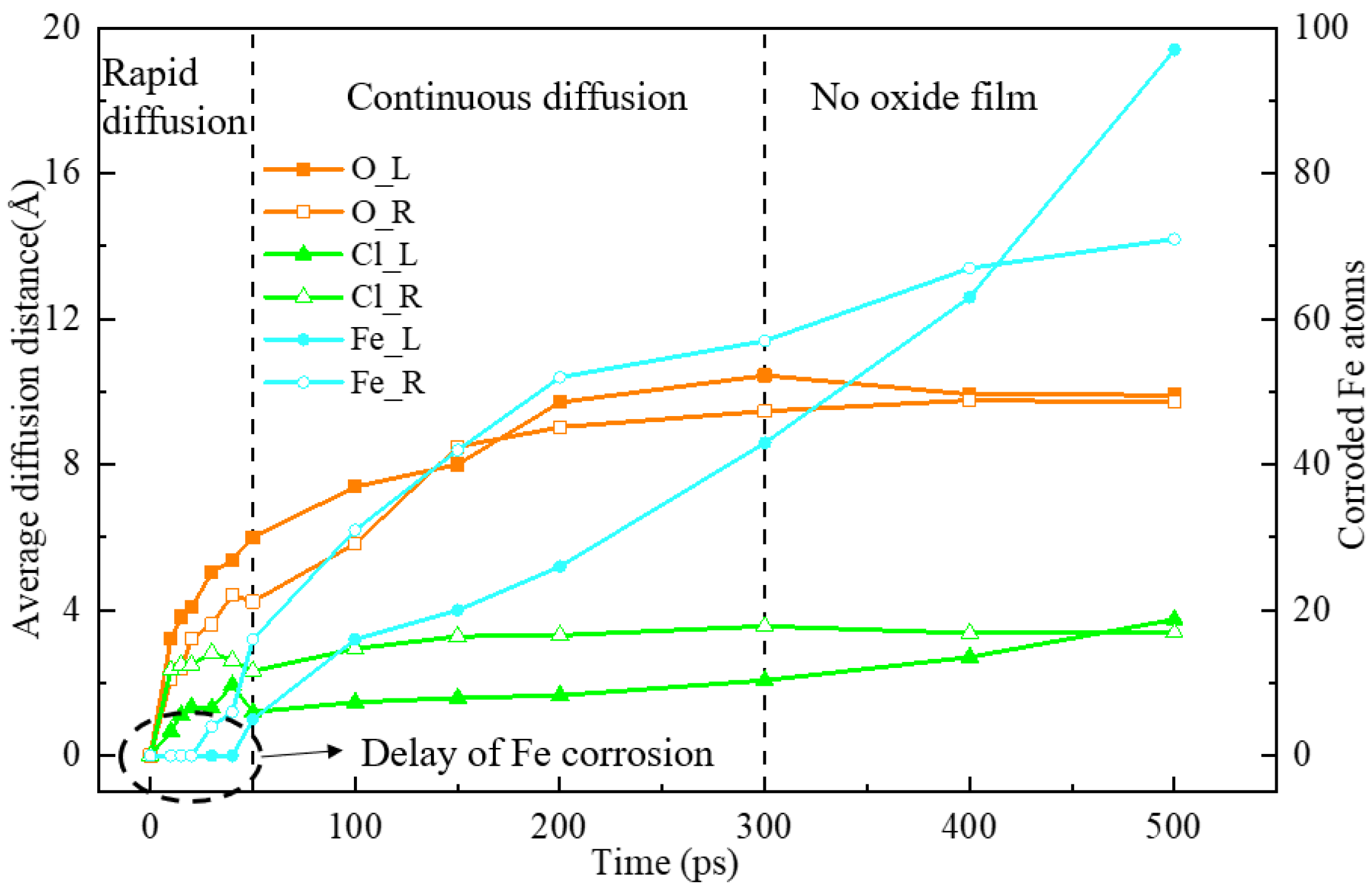
3.2. Role of Intact/Damaged Oxide Film in Chlorine Corrosion

Model A shows that Fe2O3 is more resistant to chlorine corrosion. However, the simulation results change significantly when the iron oxide film covers the surface of pure iron. Normally, the iron oxide rust on the iron surface is a loose and porous structure. Therefore, a gap is designed in the iron oxide layer on the right side of model B to simulate the effect of rust voids on corrosion protection. Figure 4 shows that the Fe2O3 film will gradually mix with the iron atomic layer to form FexOy mixtures, which will eventually be corroded by chlorine gas and hydrogen chloride. A gap is evident on the right side of the film, which is corroded earlier. The gap gradually expands, and thus the Fe2O3 film structure rapidly changes and is eventually completely corroded.
Figure 5 shows the distribution of iron atom numbers at the beginning and end (t = 0.5 ns) of the simulation of model B. At the beginning of the simulation, the Fe2O3 layer on the right side of model B has a gap defect, so the number of iron atoms is slightly less than that on the left side. After the simulation, the numbers of corroded iron atoms on both sides are 97 (left) and 71 (right). Among them, the numbers of iron atoms moved by the Fe2O3 layers on both sides are 80 (left) and 48 (right). Therefore, only 17 (left) and 23 (right) iron atoms come from the iron’s atom layer; that is, 2.25% and 3.04% of the iron atoms on both sides, respectively, were corroded (calculated from 756 iron atoms on each side, as shown in Table 1). For such simulation results, we believe that due to the gap defect on the right side, chlorine and hydrogen chloride can directly react with iron atoms through the gap of the Fe2O3 layer, so the side with the gap has a higher probability of iron corrosion. In addition, further analysis of the oxygen and chlorine diffusion behavior is required.
The diffusion of oxygen and chlorine is a remarkable phenomenon. It is found that the diffusion processes of oxygen and chlorine are similar and can be divided into three stages: rapid diffusion, continuous diffusion, and no oxide film (stable), corresponding to the reduction of the oxide film, the decomposition of the oxide film, and the corrosion of pure iron, respectively. In order to quantitatively analyze the diffusion of elements, the diffusion distances of oxygen and chlorine relative to their respective starting lines are averaged. The starting line of oxygen is the boundary line between Fe2O3 and iron, whereas the starting line of chlorine is the boundary line between Fe2O3 and gas. Only the atoms passing through the reference line are analyzed (the direction shown in Figure 4). Initially, chlorine and hydrogen chloride continuously collided with the Fe2O3 surface, but the reaction was difficult. By contrast, the oxygen in the Fe2O3 quickly diffuses into pure iron. Figure 6 shows that 0–50 ps is the rapid diffusion stage of elements. The average diffusion distance of oxygen reaches 6 Å(O_L) or 4.24 Å(O_R). Oxygen continues to spread at a high rate after the rapid diffusion stage and stabilizes after approximately 300 ps. Due to the presence of the gap on the right side of the oxide film, the oxygen concentration is lower. Accordingly, the overall diffusion distance of oxygen on the right side is slightly lower than that on the left side but tends to be consistent in the later stage.
As oxygen in the Fe2O3 diffuses into the interior of the pure iron, the structure of the Fe2O3 layer changes. The chlorine dissociated by the chlorine gas and hydrogen chloride replaces oxygen to bond with iron. The amount and rate of Cl diffusion into iron are significantly smaller than those of oxygen due to the Fe2O3 layer inhibition. The average spreading distances at 0–50 ps are 1.2 Å(Cl_L) and 2.33 Å(Cl_R). Sufficient oxygen transfer is needed to cause defects in the Fe2O3 layer near the side of the gas and react with chlorine and hydrogen chloride. The average diffusion distance of Cl increases at an extremely slow rate after 50 ps until the end of the simulation. The hole in the oxide film makes the diffusion distance of the right Cl always higher than that of the left side. However, the diffusion distances tend to be the same in the later stage because of the disappearance of the oxide film.
In this work, the corrosion degree is described by the number of corroded iron atoms and contains two parts: from the Fe and Fe2O3 layers. The corrosion degree starts to develop in the rapid diffusion stage of the element. However, a certain delay relative to the diffusion of oxygen and chlorine (Figure 6, approximately 20–40 ps, 40–80% of the rapid diffusion stage) can be observed because oxygen diffusion is required to reach a certain amount for the reaction between chlorine and FexOy. On the right side, the oxidation time is incomplete, and the corrosion start time is early; that is, the delay time is relatively short. The number of corroded iron atoms on the left side is nearly linear, while the growth rate on the right side gradually decreases. At 300 ps, Fe_L and Fe_R are 43 and 57, and the numbers of molecules on both sides of the Fe2O3 film are 40 and 24 (Table 1). The left oxide film is nearly obscured (completely changed into FexOy mixture), and the right one is completely corroded. When the simulation entered the late stage (>300 ps), the oxide film on the left side was gradually corroded; therefore, the protective effect on the iron atomic layer was greatly reduced. Since the oxide film on the right side has a gap defect and the delay time is lower than that on the left side, the destruction of the complete oxide film on the left side has a greater impact on the number of corroded iron atoms in the late stage. In addition, the number of iron atoms on the left and right sides is different. This is the reason why the increasing trend of the number of corroded iron atoms on the left side is more severe than that on the right side in the late stage. It can also be explained well from the simulation results in Figure 4.
In the slow diffusion stage of Cl (t > 50 ps), the number of corroded Fe atoms increases at a fast rate. This finding indicates that the diffusion ability of Cl to iron oxide is poor. The increase in the diffusion distance is mainly due to the gas–solid interface movement caused by iron corrosion. After the delay time, the chlorine diffusion also represents the iron oxide/iron corrosion. In addition, Fe_R is always larger than Fe_L at 0–400 ps. Moreover, Fe_R has more parts from the iron layer than Fe_L even though it is surpassed in the later stage. This manifestation indicates that the Fe2O3 film with a gap has poor protection. In the biomass combustion process, the oxide film produced on the metal wall often contains various defects, such as cracks and holes, and thus has little protection.
Our molecular dynamics simulation results are in trend with some experimental results. Król et al. [24] placed the St41K (Fe 98.868; Cr0.02; P 0.01; Si 0.02; Mn 0.87; Ni 0.01; Mo 0.001; Al, 0.043; S 0.008; C 0.15) boiler steel sample in the environment of a boiler furnace for 1152 h at 1023–1173 K to observe the chlorine corrosion phenomenon. The experimental results are shown in Figure 7. Figure 7a shows that the surface of the sample is covered with a layer of porous corrosion products. The outer porous surface of the St41K boiler steel is mainly composed of sulfur and chlorine-containing iron oxides. Approximately 200 µm of a pure iron oxide intermediate layer with a distinct crystal structure can be observed between the corrosion layer and the metal surface (Figure 7b). The presence of chlorine in pt1, pt2, and pt3 indicates that chlorine diffuses into the metal through the corrosion product layer (Figure 7c). The experimental results of Król et al. can be verified with model B. We can also summarize the corrosion diffusion behavior of chlorine in this system.
In summary, the corrosion of iron oxide/iron system by chlorine can be divided into two processes (Figure 8): (1) the oxygen diffusion from iron oxide to iron, which changes the structure of the iron oxide; (2) the reaction of chlorine on the surface of iron oxide or the direct reaction with iron through the iron oxide film. Both processes occur nearly simultaneously. However, process 2 lasts longer because the oxide film has far fewer molecules than the gas.

3.3. Role of Water

Biomass fuel has a large amount of water, and its material composition contains hydrogen, so its flue gas often contains a large amount of water vapor. The corrosion process of the system in an aqueous atmosphere is studied. Figure 9 shows the corrosion of the iron/iron oxide system over time with aqueous chlorine and hydrogen chloride. The conditions on both sides are basically the same due to the symmetry.
The amount of oxygen that diffuses into the iron layer is higher in model C than in model B (dry chlorine and hydrogen chloride corrosion). The statistics results show that the number of oxygen atoms on the gas side at the end of the simulation is less than the initial time. This finding indicates that a large amount of water reacts with iron after the destruction of the iron oxide layer. Water makes chlorine and hydrogen chloride dissociable, thereby providing a high density of chlorine, and water can react with iron at high temperatures. Accordingly, the reaction at the gas–solid interface begins early, and the reaction rate is fast. Figure 10 shows the distribution of iron atoms in model C. The number of corroded iron atoms on the left side is 116, of which 36 from the iron atomic layer (756) is approximately 4.76%. The right side is approximately 4.50%, which is similar to the left side. Therefore, the corrosion ratio of the Fe layer in model C is 4.63%.
Table 2 summarizes the corrosion amount of the iron layer in the models, excluding the part from iron oxide. A total of 17 iron atoms are corroded from the iron atomic layer. When the oxide film is damaged, or the mixed gas contains water, the corrosion will be further enhanced, and the corrosion amount is 23 and 71 (36 + 35), respectively. It follows that the presence of water in chlorine and hydrogen chloride mixed gas will aggravate the corrosion of iron atoms.

4. Conclusions

ReaxFF-MD was used to simulate the corrosion of an iron oxide-coated iron matrix by chlorine and hydrogen chloride mixed gas under the high temperature of 1300 K. The difference between the complete iron oxide film and notched film in the corrosion process and the role of water in the corrosion process were studied.
Ferric oxide is stable and is resistant to corrosion by chlorine and hydrogen chloride. When iron oxide is coated on the surface of pure iron, oxygen atoms easily diffuse into pure iron, and the corrosion resistance is greatly weakened. Finally, the corrosion number of the pure iron layer is about 2.25%. Therefore, the iron oxide film can only hinder iron corrosion by chlorine and hydrogen chloride to a certain extent. When the oxide film is damaged or contains water in the mixed gas, corrosion is further enhanced, and the corrosion amount is about 3.04% and 4.63%, respectively.
The diffusion processes of oxygen and chlorine are similar and can be divided into three stages: rapid diffusion, continuous diffusion, and no oxide film (stable). The diffusion distance of oxygen is always greater than that of chlorine. The damage to the right oxide film makes the diffusion distance of oxygen slightly lower than that of the left one (complete oxide film). The diffusion distance of chlorine is higher than that of the left one, but the difference gradually decreases in the later stage. The iron oxide/iron corrosion is delayed relative to elemental diffusion, which is approximately 40–80% of the rapid diffusion stage. The delay time on the side of the complete oxide film is relatively long. The diffusion distance of chlorine mainly comes from the deviation of the gas–solid interface caused by corroded iron.

Author Contributions

Conceptualization, L.Y. and L.T.; methodology, L.Y. and N.Y.; software, L.Y., N.Y. and Y.Y.; validation, N.Y. and Y.Y.; formal analysis, L.Y., N.Y., Y.Y. and Y.Q.; investigation, Y.Q., L.Y., N.Y. and Y.Y.; data curation, L.Y., N.Y. and Y.Y.; writing—original draft preparation, L.Y., N.Y. and Y.Y.; writing—review and editing, Y.Q., L.Y., N.Y. and Y.Y.; visualization, Y.Q., L.Y., N.Y. and Y.Y.; supervision, L.T., L.W. and S.Y.; project administration, L.T., S.Y. and L.W.; funding acquisition, L.T. All authors have read and agreed to the published version of the manuscript.

Funding

This research received no external funding.

Institutional Review Board Statement

Not applicable.

Informed Consent Statement

Not applicable.

Data Availability Statement

Not applicable.

Conflicts of Interest

The authors declare no competing financial interest.

References

  1. Antunes, R.A.; de Oliveira, M.C.L. Corrosion in biomass combustion: A materials selection analysis and its interaction with corrosion mechanisms and mitigation strategies. Corros. Sci. 2013, 76, 6–26. [Google Scholar] [CrossRef]
  2. Wang, Y.; Sun, Y.; Yue, M.; Li, Y. Reaction Kinetics of Chlorine Corrosion to Heating Surfaces during Coal and Biomass Cofiring. J. Chem. 2020, 2020, 2175795. [Google Scholar] [CrossRef]
  3. Cantatore, V.; Ogaz, M.A.O.; Liske, J.; Jonsson, T.; Svensson, J.-E.; Johansson, L.-G.; Panas, I. Oxidation Driven Permeation of Iron Oxide Scales by Chloride from Experiment Guided First-Principles Modeling. J. Phys. Chem. C 2019, 123, 25957–25966. [Google Scholar] [CrossRef]
  4. Liu, Y.; Fan, W.; Wu, X.; Zhang, X. Chlorine-Induced High-Temperature Corrosion of Boiler Steels Combusting Sha Erhu Coal Compared to Biomass. Energy Fuels 2018, 32, 4237–4247. [Google Scholar] [CrossRef]
  5. Chen, T.C.; Xiang, J.H.; Jiang, L.F.; Xiong, J.; Bai, L.Y.; Xu, X.H.; Xu, X.C. High-temperature Corrosion Behavior of Q235 Steel in Oxidizing Atmosphere Containing Chlorine. J. Chin. Soc. Corros. Prot. 2021, 41, 560–564. [Google Scholar] [CrossRef]
  6. Maurice, V.; Marcus, P. Progress in corrosion science at atomic and nanometric scales. Prog. Mater. Sci. 2018, 95, 132–171. [Google Scholar] [CrossRef]
  7. Zi, M.; Chen, D.; Wu, G. Molecular dynamics simulation of methane hydrate formation on metal surface with oil. Chem. Eng. Sci. 2018, 191, 253–261. [Google Scholar] [CrossRef]
  8. El-Hajjaji, F.; Messali, M.; Aljuhani, A.; Aouad, M.; Hammouti, B.; Belghiti, M.; Chauhan, D.S.; Quraishi, M. Pyridazinium-based ionic liquids as novel and green corrosion inhibitors of carbon steel in acid medium: Electrochemical and molecular dynamics simulation studies. J. Mol. Liq. 2018, 249, 997–1008. [Google Scholar] [CrossRef]
  9. Zhang, W.; Chen, X.; van Duin, A.C.T. Isotope Effects in Water: Differences of Structure, Dynamics, Spectrum, and Proton Transport between Heavy and Light Water from ReaxFF Reactive Force Field Simulations. J. Phys. Chem. Lett. 2018, 9, 5445–5452. [Google Scholar] [CrossRef]
  10. Batuer, A.; Chen, D.; He, X.; Huang, Z. Simulation methods of cotton pyrolysis based on ReaxFF and the influence of volatile removal ratio on volatile evolution and char formation. Chem. Eng. J. 2020, 405, 126633. [Google Scholar] [CrossRef]
  11. Sun, Y.; Zhai, Z.; Tian, S.; Chen, X. Effect of oxidation on crack propagation of Si nanofilm: A ReaxFF molecular dynamics simulation study. Appl. Surf. Sci. 2019, 480, 1100–1108. [Google Scholar] [CrossRef]
  12. Dongol, R.; Wang, L.; Cormack, A.; Sundaram, S. Molecular dynamics simulation of sodium aluminosilicate glass structures and glass surface-water reactions using the reactive force field (ReaxFF). Appl. Surf. Sci. 2018, 439, 1103–1110. [Google Scholar] [CrossRef]
  13. Sim, H.S.; Yetter, R.A.; Hong, S.; van Duin, A.C.; Dabbs, D.M.; Aksay, I.A. Functionalized graphene sheet as a dispersible fuel additive for catalytic decomposition of methylcyclohexane. Combust. Flame 2020, 217, 212–221. [Google Scholar] [CrossRef]
  14. Jin, Y.; Duan, F.; Mu, X. Functionalization enhancement on interfacial shear strength between graphene and polyethylene. Appl. Surf. Sci. 2016, 387, 1100–1109. [Google Scholar] [CrossRef]
  15. Yang, Z.; Sun, Y.; Ma, F.; Lu, Y.; Zhao, T. Pyrolysis mechanisms of graphene oxide revealed by ReaxFF molecular dynamics simulation. Appl. Surf. Sci. 2020, 509, 145247. [Google Scholar] [CrossRef]
  16. Jeon, B.; Van Overmeere, Q.; van Duin, A.C.T.; Ramanathan, S. Nanoscale oxidation and complex oxide growth on single crystal iron surfaces and external electric field effects. Phys. Chem. Chem. Phys. 2012, 15, 1821–1830. [Google Scholar] [CrossRef]
  17. Liu, J.; Zhao, C.-J.; Lu, W.-Q. Molecular dynamics simulation on the corrosion characteristics of iron in liquid lead. Ann. Nucl. Energy 2018, 116, 31–41. [Google Scholar] [CrossRef]
  18. Li, W.; Mi, Z.; Qin, S.; Gao, L.; He, J.; Guo, L.; Qiao, L. CS-AFM study on Pb-induced degradation of passive film on nickel-based alloy in high temperature and high pressure water. Corros. Sci. 2018, 144, 249–257. [Google Scholar] [CrossRef]
  19. DorMohammadi, H.; Pang, Q.; Árnadóttir, L.; Isgor, O.B. Atomistic simulation of initial stages of iron corrosion in pure water using reactive molecular dynamics. Comput. Mater. Sci. 2018, 145, 126–133. [Google Scholar] [CrossRef]
  20. Farzi, N.; Hydarifar, M.-H.; Izadi, M.E. The investigation of surface corrosion of Fe3C in H2SO4 solution and the role of thiophene as an inhibitor by ReaxFF molecular dynamics. Mater. Chem. Phys. 2022, 283, 125984. [Google Scholar] [CrossRef]
  21. Van Duin, A.C.T.; Dasgupta, S.; Lorant, F.; Goddard, W.A. ReaxFF: A Reactive Force Field for Hydrocarbons. J. Phys. Chem. A 2001, 105, 9396–9409. [Google Scholar] [CrossRef] [Green Version]
  22. Chenoweth, K.; van Duin, A.C.T.; Goddard, W.A. ReaxFF Reactive Force Field for Molecular Dynamics Simulations of Hydrocarbon Oxidation. J. Phys. Chem. A 2008, 112, 1040–1053. [Google Scholar] [CrossRef] [PubMed] [Green Version]
  23. Manyele, S.V. Analysis of Medical Waste Incinerator Performance Based on Fuel Consumption and Cycle Times. Engineering 2012, 4, 625–635. [Google Scholar] [CrossRef]
  24. Król, D.; Motyl, P.; Poskrobko, S. Chlorine Corrosion in a Low-Power Boiler Fired with Agricultural Biomass. Energies 2022, 15, 382. [Google Scholar] [CrossRef]
Figure 1. Simulation models (AC).
Energies 15 04237 g001
Figure 2. Last configurations of model A. (Green is chlorine, white is hydrogen, aqua is iron and yellow is oxygen.)
Energies 15 04237 g002
Figure 3. Schematic diagram of O and H combination process. (Hydrogen chloride corrodes iron oxide, red is marked oxygen, the rest of oxygen is yellow, white is hydrogen, aqua is iron, chlorine is not shown.)
Energies 15 04237 g003
Figure 4. Temporal variations of model B. (Green is chlorine, white is hydrogen, aqua is iron and yellow is oxygen.)
Energies 15 04237 g004
Figure 5. Initial and last distribution of Fe in model B.
Energies 15 04237 g005
Figure 6. Average diffusion distance of elements and number of corroded iron atoms in model B. L means the left side with a complete oxide film, and R means the right side with an incomplete one.
Energies 15 04237 g006
Figure 7. Chlorine corrosion experimental study by Król et al. [24]. (a) A layer of porous corrosion products; (b) the numbers 1–3 as marked points represent the chemical composition of the surface of the St41K boiler steel in the planes pt1, pt2, and pt3 on the microscopic photo; (c) microscopic photo (SEM) of the surface of the St41K boiler steel.
Energies 15 04237 g007
Figure 8. Corrosion diagram of model B. (Green is chlorine, white is hydrogen, aqua is iron and yellow is oxygen.)
Energies 15 04237 g008
Figure 9. Temporal variations of model C. (Green is chlorine, white is hydrogen, aqua is iron and yellow is oxygen.)
Energies 15 04237 g009
Figure 10. Initial and last distribution of Fe in model C.
Energies 15 04237 g010
Table 1. Details of the simulation systems.
ModelN(Fe)N(Fe2O3)N(Cl2)N(HCl)N(H2O)Size of the Simulated Box
A-40 + 40 + 406464-25.37 Å × 9.82 Å × 66.42 Å
B756 + 75640 + 24128128-25.37 Å × 9.82 Å × 147.48 Å
C756 + 75640 + 4012812812825.37 Å × 9.82 Å × 168.94 Å
Table 2. Corroded iron atoms of models.
ModelFactorCorroded Iron Atoms (Fe Layer)Proportion
A
BOxide film172.25%
Cracked oxide film233.04%
CWater714.63%
Publisher’s Note: MDPI stays neutral with regard to jurisdictional claims in published maps and institutional affiliations.

