Article

Hybrid Battery Thermal Management System with NiTi SMA and Phase Change Material (PCM) for Li-ion Batteries

1
Department of R&D—Bargem, Birikim Batteries Company, 34959 Istanbul, Turkey
2
Department of Mechatronic Engineering, Istanbul Gedik University, 34953 Istanbul, Turkey
3
Department of Civil & Environmental Engineering, Cleveland State University, Cleveland, OH 44115, USA
4
Department of Chemistry—Ångström Laboratory, Uppsala University, 75121 Uppsala, Sweden
*
Author to whom correspondence should be addressed.
Energies 2022, 15(12), 4403; https://doi.org/10.3390/en15124403
Submission received: 2 May 2022 / Revised: 7 June 2022 / Accepted: 15 June 2022 / Published: 16 June 2022
(This article belongs to the Section D1: Advanced Energy Materials)

Abstract

:
Poor heat dissipation and thermal runaway are most common in batteries subjected to fast charge or discharge and forced to work in hot or subzero ambient temperatures. For the safe operation of lithium-ion batteries throughout their lifecycle, a reliable battery thermal management system (BTMS) is required. A novel hybrid BTMS with a nickel-titanium (NiTi) shape memory alloy (SMA) actuated smart wire and phase change material (PCM) with expanded graphite (EG) is proposed in this study. A lumped electrochemical-thermal battery model is developed to analyze the efficiency of the proposed hybrid BTMS. The multiphysics BTMS is investigated by discharging at various electrical currents in both off-modes (inactivated SMA) and on-modes (activated SMA). Under on-mode BTMS operation, temperature elevation is reduced by 4.63 °C and 6.102 °C during 3 C and 5 C discharge, respectively. The proposed hybrid BTMS can be considered a competitive alternative for use in electrical vehicles due to its smart, compact, safe, and efficient performance in both cold and hot environments.

1. Introduction

Lithium-ion batteries (LIBs) have attracted much attention as a potential replacement for traditional power sources. With their high energy and power densities, low self-discharge, and long cycle life, they have been employed in a variety of applications, including mobile electronic devices, transportation, and stationary energy storage systems. To function properly, LIBs must be operated at temperatures ranging from 15 to 35 °C [1,2]. An improper operating temperature has a negative impact on battery performance and lifecycle. At higher operating temperatures, active material isolation, electrolyte degradation, changes in the solid electrolyte interface, and an increased rate of side reactions cause capacity and power fading as well as thermal runaway. On the other hand, at lower operating temperatures, reduced electrolyte ionic conductivity, increased charge transfer resistance, lithium plating, and limited diffusivity of lithium ions in electrodes all contribute to poor energy and power output [3]. Similarly, uneven temperature distribution across cells in a battery pack leads to inhomogeneous aging of the cells and, as a result, a decrease in battery pack cycle life [4]. To avoid these limitations, a reliable battery thermal management system is crucial.
The ideal BTMS must keep the battery temperature at optimal operating levels to ensure the safe and optimal operation of the LIBs. It must be able to respond quickly to changes in battery temperature and maintain a safe temperature range in a short period. Despite substantial research, there are still barriers to their broad use in terms of cost and effectiveness. There are two types of battery thermal management systems: active and passive. Active BTMSs typically use an external cooling or heating source and are most commonly seen in air-based, liquid-based, or thermoelectric-based BTMSs. On the other hand, the vast majority of passive BTMSs rely on Phase Change Material (PCM). Furthermore, hybrid studies combining these two types of BTMS approaches have been published in the literature [5]. The first passive cooling system with PCM for battery packs was first patented and commercialized by Allcell [6]. Passive cooling based on PCM has several benefits, including low cost, no need for a roaming network, compactness, and an efficient cooling effect. PCMs are also well known for maintaining a consistent temperature distribution among batteries [7]. Al Hallaj et al. [8] published a system that integrated phase change material into the battery module. The study found that the PCM-cooled battery was more efficient than the battery without PCM cooling. Goli et al. [9] proposed a new system to improve the thermal conductivity of PCM by adding graphene to it. The BTMS including 80% PCM and 20% graphene showed the lowest temperature increase. Wu et al. [10] sought to extend the work of Goli et al. by increasing the thermal conductivity of PCM with expanded graphite, transferring heat quickly with copper mesh, and creating a skeleton for BTMS. Zhao et al. [11] proposed a new design by replacing the copper mesh in the PCM and EG hybrid system with a Heat Pipe. A system comprised of PCM, copper pipes, aluminum casing, and water was proposed. This proposed system aimed to dissipate the latent heat of the PCM by increasing the thermal conductivity of the PCM with the passage of liquid through the pipes [12]. However, PCMs are unable to recover all of the latent energy potential during solidification when Li-ion batteries are utilized under extreme operating conditions, which may result in thermal runaway. Other disadvantages of PCMs include possible leakage and poor thermal conductivity. Due to its limited thermal conductivity, a PCM hinders self-internal heating of the batteries in cold environments [13,14]. To address this issue, researchers have used additive materials with high thermal conductivity such as carbon fiber [15], expanded graphite (EG) sheet [16], graphene [17], fin [18], and metal foams [19,20]. Fathabadi [21] predicted outstanding thermal performance by using a PCM-EG composite. Several studies have been conducted to address concerns about the use of PCM in BTMSs. Rao et al. [22] developed a liquid-cooled BTMS device with a pump and PVC tubes routed through metal blocks. Naresh et al. [23] added external fins made of the Al-6061 T6 alloy to the battery pack to improve thermal conductivity and reduce the battery pack temperature.
Nickel-Titanium (NiTi) shape memory alloys (SMAs) are preferred in various mechatronics applications due to their superior thermo-mechanical performance [24]. Incorporating NiTi SMA wires into the BTMS design allows for the separation of the battery and the cooler when the battery does not require cooling, and when the battery temperature rises above the acceptable temperature value, the NiTi SMA acts as a switch by connecting it to the cooler. Menglong Hao et al. [25] suggested a passive battery cooling regulator using NiTi SMA. In another study, the NiTi SMA wire is utilized as a switch, and the heat-sink is employed to offer thermal management of the battery, which can be used in either cold or hot ambient temperatures [26].
A novel hybrid thermal management system for batteries is proposed in this study. As a potential alternative BTMS, the hybrid system incorporating NiTi SMA and phase change material-expanded graphite (PCM-EG) is evaluated. The proposed novel patent-pending smart BTMS excludes the disadvantages of previous traditional BTMSs while also demonstrating promising results in terms of controlling maximum battery temperature rise, with the ability to be used modularly. In this system, which is suitable for both cold and hot environments, PCM-EG BTMSs can allow the battery to warm up in cold environments due to the switching operation in cold and hot environments, without the need for extra energy. The applicability of the proposed smart hybrid BTMS is assessed in this paper. Section 2 and Section 3 cover experimental setup and system design. Section 4 describes the model and its governing equations. The results and discussion are covered in Section 5.

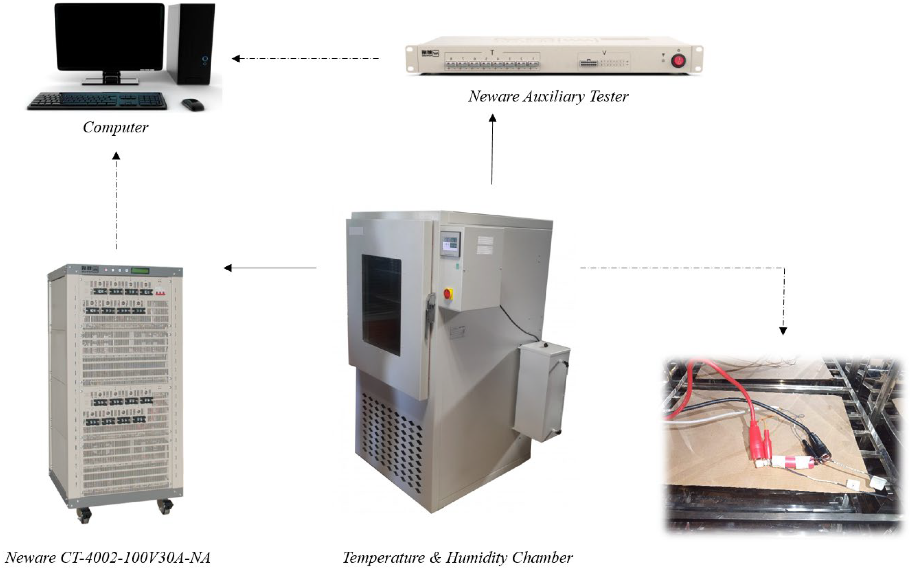
2. Experimental Setup
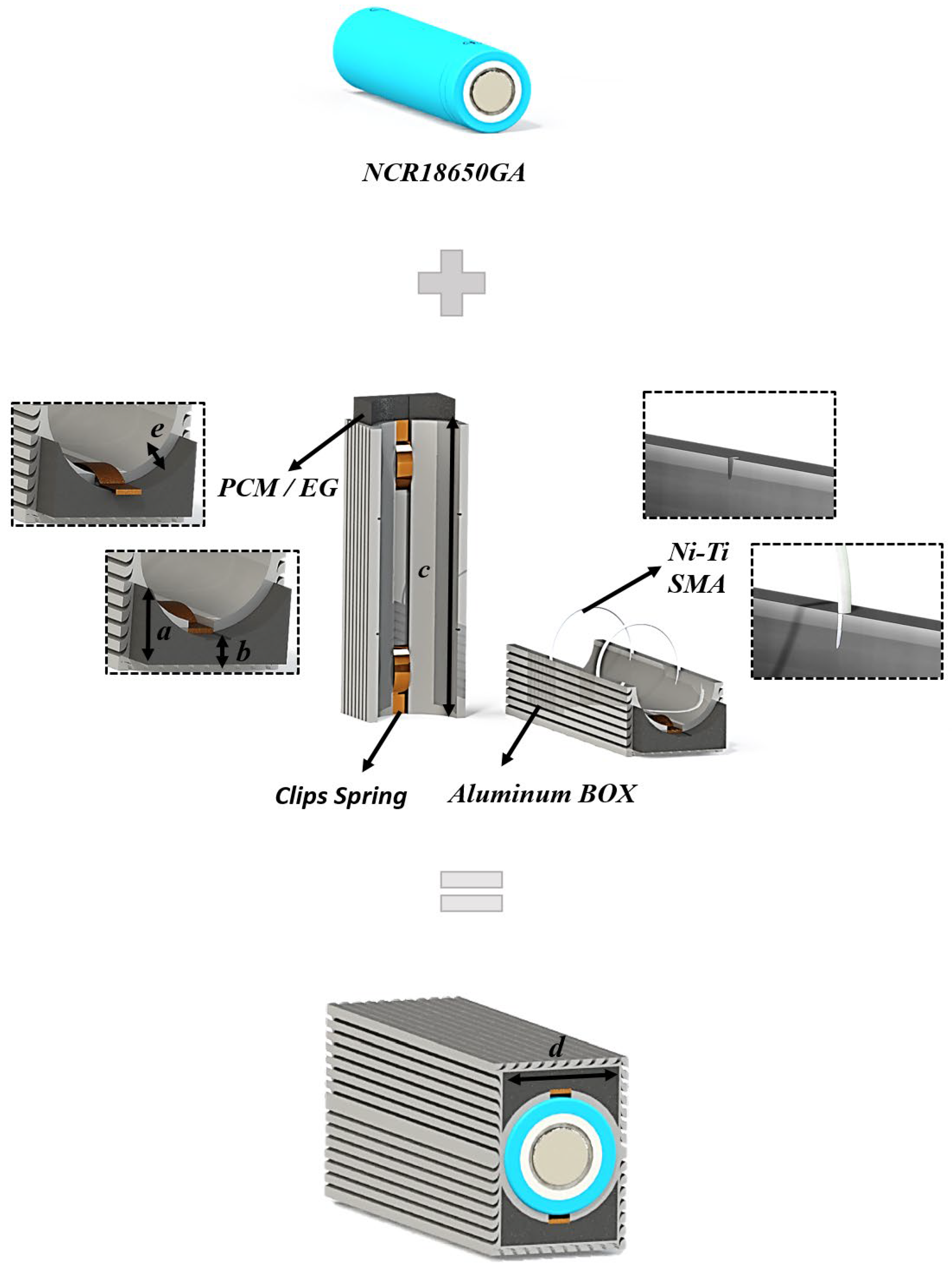
Figure 1 depicts a schematic diagram of the experimental system. Panasonic Sanyo NCR18650GA high-capacity batteries were used to study the electrochemical and thermal behavior of the cells under various operating conditions. A Neware CT-4002-100V30A-NA battery testing system was used to monitor capacity and cell surface temperature. The variation of the battery surface temperature was measured using two temperature sensors, while the ambient temperature was measured using a third sensor. The data obtained from the battery sensors, as well as the ambient temperature, were measured using the Neware Auxiliary Tester. All experiments are conducted in a KK 240 TOP + FIT model POL-EKO APARATURA thermal chamber to maintain a constant ambient temperature. Electrochemical tests included constant current-constant voltage (CCCV) charging and constant current (CC) discharge. Table 1 shows the charge and discharge protocol for the battery. A computer was used to record the output data.
In summary, the battery is charged with 1.4750 A and has a voltage cut-off limit of 4.2 V in galvanotactic mode, changing to potentiostatic mode until the current drops to 0.0670 A. After that, the cells are given 30 min to rest. The cells are then discharged at different current rates (1–3 C) until the voltage drops to 2.5 V, followed by a 30 min rest period. The corresponding battery specifications are summarized in Table 2.

3. System Design

Figure 2 shows the BTMS design, which includes an aluminum-encased PCM-EG, a NiTi shape memory alloy spring, and a commercial 18,650 battery. The design was drawn and assembled using the Solidworks® program. The maximum thickness (Figure 2a), minimum thickness (Figure 2b), and length (Figure 2c) of the PCM-EG composite were designed to be 9.6 mm, 3.12 mm, and 6 mm, respectively. For the aluminum box, Al6061 was chosen. The width of the aluminum can is 22 mm (Figure 2d), and the distance between the PCM-EG and the battery is 1.60 mm (Figure 2e). The aluminum box’s function is to hold the PCM-EG composite and prevent leakage, as well as to increase heat dissipation rate and act as a cooling fin. The NiTi shape memory alloy wire has a diameter of 0.7 mm and is intended to switch between on and off modes. Before the battery is inserted, two clips springs are inserted into the aluminum box. The gap between the aluminum box and the battery is created by these springs. The compressive spring has a diameter of 3.50 mm and a length of 15 mm. It is attached to the aluminum box on both ends. The NiTi wire’s working mechanism is based on its temperature dependence behavior. In other words, the length varies with battery temperature through the contact point. When the battery reaches the recommended maximum temperature, the NiTi SMA wires contract and the gap between the battery and the aluminum case is reset, allowing contact between the battery surface and the aluminum-cased PMC-EG BTMS (on-mode), which dissipates heat to the environment via conduction and then convection. When the battery cools, the NiTi SMA wires return to their original lengths (off-mode), and clip springs create a space between the cell and the BTMS. During this process, excess heat is removed from the battery, and the smart BTMS is designed to keep the battery temperature within the specified range. Figure 3 illustrates a simplified representation of the on-mode and off-mode.

4. Model Description

4.1. A Lumped Model

The lumped battery electrochemical-thermal model is based on the work of [29] and [30]. The model is a semi-empirical model that uses the difference between the battery open-circuit voltage and overpotentials due to linear ohmic resistance, non-linear charge transfer resistance, and diffusion resistance to returning a time-dependent formulation for cell voltage. Thus, the terminal voltage could be estimated as a function of the cell open-circuit potential, the concentration overpotential, the ohmic overpotential, and the activation overpotential, as in Equation (1), whereas the parameters’ characteristics are temperature-dependent based on the Arrhenius law.
E c e l l = E O C V ( S O C ¯ , T ) + η I R + η a c t + η c o n c
where E O C V ( S O C ¯ , T ) is the cell open circuit voltage as a function of average State Of Charge (SOC) and temperature, which is expressed as
E O C V ( S O C ¯ , T ) = E O C V , r e f ( S O C ) + ( T T r e f ) E O C V , r e f ( S O C ) T
The ohmic overpotential is given as
η I R = η I R , 1 C ( T ) I a p p I 1 C
where η I R , 1 C ( T ) , I a p p , and I 1 C denote the temperature-dependent ohmic overpotential at 1 C, applied current, and corresponding current at 1 C, respectively. Temperature dependency of ohmic overpotential is derived based on the Arrhenius law as
η I R , 1 C   ( T ) = η I R , 1 C , r e f e x p ( E a , I R R ( 1 T 1 T r e f ) )
where E a , I R denotes the activation energy for ohmic overpotential. The activation overpotential is given as
η a c t = 2 R T F a s i n h ( I a p p 2 J 0 ( T ) I 1 C )
where the temperature dependency of local current density is expressed as
J 0 ( T ) = J 0 , r e f e x p ( E a , J 0 R ( 1 T 1 T r e f ) )
The last overpotential term, the concentration overpotential, is given as in Equation (7):
η c o n c = E O C V ( S O C | x = 1 , T ) E O C V ( S O C ¯ , T )
where S O C | x = 1 and S O C ¯ denote the surface SOC and the average SOC, and are given as in Equations (8) and (9), respectively:
S O C | X = 1 = τ I a p p 3 Q c e l l , 0
S O C ¯ = 0 1 S O C X 2 d X
The cell temperature is calculated using the lumped thermal model as follows:
ρ C p T t = x ( k x T x ) + y ( k y T y ) + z ( k z T z ) + Q ˙ g e n
where ρ and C p denote the lumped battery density and battery heat capacity; k x , k y , and k z denote the lumped battery thermal conductivity in x, y, and z directions, respectively; and Q ˙ g e n is the total heat generation term, which could be calculated as
Q ˙ g e n = I ( E c e l l E O C V ( S O C ¯ ) + T E O C V ( S O C ¯ ) T )

4.2. Governing Equations for Phase Change Material
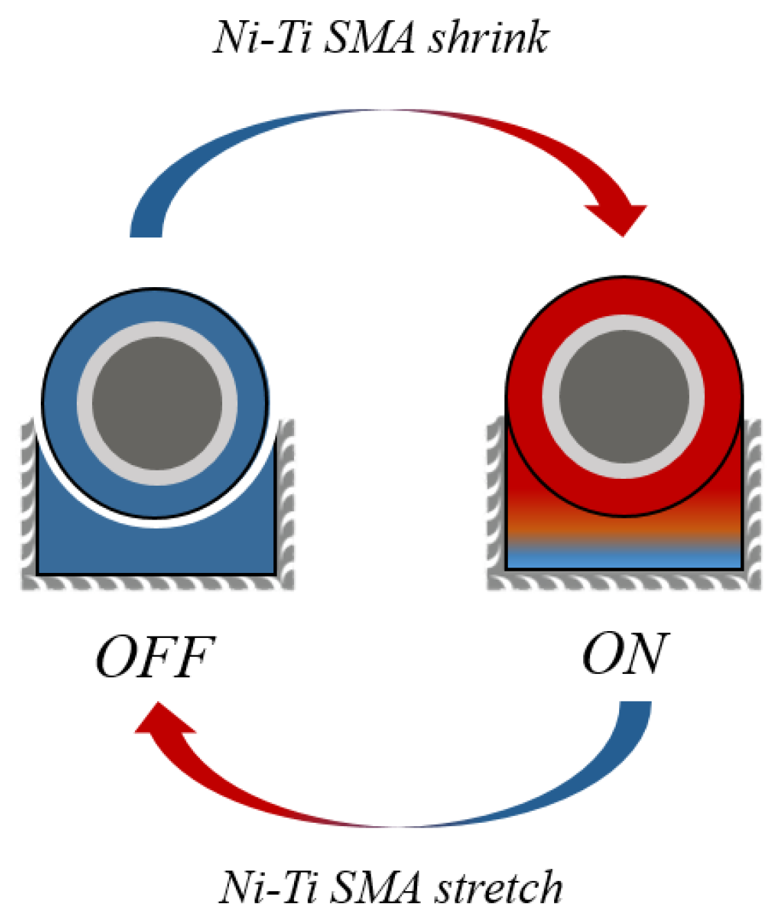
The amount of heat absorbed by the PCM can be calculated using the following equation:
Q P C M = m C p , s ( T 1 T m ) + m L s l + m C p , l ( T 2 T m )
The physical properties of the PCM are derived as
ρ P C M = θ s ρ s + θ l ρ l
k = θ s k s + θ l k l
C p , P C M = 1 ρ P C M ( θ s ρ s C p , s + θ l ρ l C p , l ) + L s l α m T
where
α m = 1 2 θ l ρ l θ s ρ s θ l ρ l + θ s ρ s
θ l + θ s = 1

4.3. NiTi SMA Model

The actuation strain obtained from the NiTi’s finite element (FE) simulation was used to select the NiTi SMA for the specific BTMS application. To simulate the thermomechanical responses of the NiTi SMA, the previously developed three-dimensional material model was used as a user material (UMAT) in the Abaqus FE commercial code. The direct implementation of the UMAT model in the FE code allowed us to account for kinematical nonlinearities due to large deformations, rate-dependent material behaviors, and different responses under various loading controls/modes to simulate typical thermomechanical loading scenarios. Here, the fully implicit, backward Euler difference integration scheme was used. A detailed explanation of the main model equations and parameters, as well as experimental validation, can be found in Refs. [31,32].
Fundamentally, the 3D model is characterized by a set of state variables and multiple inelastic mechanisms that capture the energy dissipation and energy storage typically associated with the nonlinear deformation of shape memory alloys. Following the hypothesis of additive decomposition, the total strain comprises the elastic/viscoelastic/reversible part ( ε i j E ) and inelastic/viscoplastic/irreversible ( ε i j I ) part, as seen in Equation (17):
ε i j = ε i j E + ε i j I  
Following the unified approach of describing the inelastic aspects (plasticity, creep, stress relaxation, etc.) of material deformation, the inelastic strain tensor here, ε i j I , also accounts for the transformation-induced strains occurring due to the detwinning of martensite variants, the reorientations of martensitic variants, and the internal grain boundary dislocations. Moreover, Gibb’s complementary energy function, Φ , and dissipation function, Ω , are used to characterize the stored and dissipated energies associated with the stress–strain–temperature hysteresis responses of SMAs. In particular, with the subscripts R and IR representing the reversible and irreversible parts, respectively, the equations for Φ and Ω depend on the external stress ( σ i j ) , internal state variables ( α i j ( b ) ), and the effective stress ( σ i j α i j ), such that
Φ ( σ i j , α i j ( b ) ) = Φ R ( σ i j ) + Φ I R ( α i j ( b ) ) = 1 2 σ i j E i j k l 1 σ k l + σ i j ε i j I + b = 1 6 H ¯ ( b )
Ω ( σ i j , α i j ( b ) ) = Ω ( ( σ i j α i j ) , α i j ( b ) ) = κ 2 F n 2 μ d F
The term α i j is the total back stress tensor obtained from the summation of the individual internal back stresses for each of the six internal mechanisms, b, used to represent the microstructural mechanisms (internal microplasticity, dislocations, micro defects, etc.) driving the deformation processes of the NiTi shape memory alloy.
α i j = b = 1 6 α i j ( b )  
In the original model, the first three mechanisms (i.e., superscript b = 1, 2, and 3) provide the energy storage, and the last three (i.e., b = 4, 5, and 6) account for the energy dissipation; these mechanisms can be made temperature- and/or stress-dependent.
The stiffness modulus tensor E i j k l of the fourth-order (in Equation (18)) is obtained using Young’s modulus, E , and Poisson’s ratio, ν , with δ i j = Kronecker delta:
E i j k l = v E ( 1 + v ) δ i j δ k l + E 2 ( 1 + v ) ( δ i k δ j l + δ i l δ j k )
It is worth mentioning that, unlike other existing models which utilize two different values to represent the Elastic constants at the martensite and austenite states [33], we here use a single value of E = 60 GPa. This represents the average elastic moduli measured at the austenite and martensite phases of the NiTi specimen. Typical for most metallic materials, a Poisson’s ratio of ν = 0.3 is selected.
In Equation (18), the viscoplastic function H ¯ ( b ) is dependent on the internal state stress tensor α i j ( b ) or its conjugate internal strain γ i j ( b ) for the specific mechanisms.
H ¯ ( b ) = { κ ( b ) 2 1 h ¯ ( g ( b ) ) d G ( b ) ,   f o r   b = 1 ,   2 ,   3 κ ( b ) 2 1 h ( G ( b ) ) d G ( b ) ,   f o r   b = 4 ,   5 ,   6  
where
g ( b ) = γ i j ( b ) M i j k l γ k l ( b )
γ i j ( b ) = Φ I R α i j ( b )
M i j k l = 1 2 ( δ i k δ j l + δ i l δ j k ) 1 3 δ i j δ k l
G ( b ) = 1 2 κ ( b ) 2 ( α i j ( b ) M i j k l α k l ( b ) )
The scalar functions h ¯ for the energy storage differs between mechanisms (b = 1, 2, and 3), as given by subsequent Equation (27). On the other hand, for the dissipative mechanisms, a function h with internal stress arguments and exhibited saturation states are used as defined in the upcoming Equation (28). The Heaviside term, h ^ ( L ) , which is dependent on the loading index, L = α i j ( b ) Γ i j , is also used to account for the effects of non-proportional loadings.
h ¯ = { ρ κ ( b ) H ( b ) ( g ( b ) ) ( β ( b ) 1 ) κ ( b ) + H ( b ) ( g ( b ) ) β ( b ) , f o r   b = 1 ,   2 ; ρ H ( b ) [ 1 + ( ( g ( b ) ) κ ( b ) / H ( b ) ) β ( b ) ] , f o r   b = 3
h = H ( b ) [ 1 ( ( G ( b ) ) ρ ( b ) ) β ( b ) h ^ ( L ) ] ,   f o r   b = 4 ,   5 ,   6
where
Γ i j = F ( σ i j α i j )
ρ = 1 + c d 1 + c d + k 3
k 3 = cos 3 θ
Here, θ is Lode’s angle, calculated from the invariants of the effective stress ( σ i j α i j ) .
The transformation function, F, in the previous Equation (18) is defined by as follows:
F = 1 κ 2 [ 1 2 ρ 2 ( σ i j α i j ) M i j k l ( σ k l α k l ) ]
In the above equations, the parameters c and d are used to account for asymmetry in stress–strain–temperature responses under tension and compression; n and μ are rate-dependent parameters that account for the severity of the differences in the rate of loading on the stress–strain responses; κ is a threshold value that marks the beginning of detwinning/reorientation of the martensite (M) phase (at T < Mf), and/or stress-induced M from the austenite (A) phase (at T > Af). The terms H ( b ) ,   β ( b ) , and κ ( b ) constitute the material parameters that distinguish the intrinsic behavior of the hardening mechanisms. Specifically, the values for H ( b ) , and   β ( b ) for the active mechanisms control the rate of saturation of the threshold parameters κ ( b ) , which collectively affect the cyclic stress–strain–temperature responses of the shape memory alloy under isobaric or isothermal cycles. The fourth-order tensor of elastic stiffness moduli, M i j k l , defines material orientation. For the current simulation study, the material responses are presented in tension only; hence, the ATC parameters were not considered relevant here.
The strain and stress rates are given as
ε ˙ i j ε ˙ i j I = d d t ( Φ R   σ i j ) = E i j k l 1   σ ˙ k l
σ ˙ k l = E i j k l   ( ε ˙ i j ε ˙ i j I )
where
ε ˙ i j I = Ω   σ i j = F n 2 μ M i j k l (   σ k l α k l )
α ˙ k l ( b ) = [ 2 Φ i α i j ( b )     α k l ( b ) ] 1   γ ˙ i j ( b )
with
γ ˙ i j ( b ) = Ω α i j ( b )
Overall, 23 parameters were needed to simulate the response of the NiTi under isobaric thermal cycle conditions (see Section 5.2).

5. Results and Discussion

5.1. Model Validation

The experimental measurements described in Section 2 have been used to validate the lumped battery model. To this end, the battery terminal voltage and average temperature have been validated at 1 C, 2 C, and 3 C discharge current rates. The BOBYQA (Bound Optimization BY Quadratic Approximation) optimization tool in COMSOL Multyphysics 5.6 has been used to optimize the model outputs and, subsequently, to estimate parameters. Figure 4 illustrates the battery voltage and average temperature validation results, as well as their associated errors, at three different discharge rates. The error rates are calculated as
%   e r r o r = | V E x p V S i m V E x p × 100 |
where V E x p and V s i m denote the measured voltage by experiment and calculated voltage from the simulation, respectively. The optimized parameters are listed in Table 3.

5.2. NiTi SMA Model Results

The designed BTMS necessitates training the NiTi SMA by subjecting it to thermal cycles ranging from 15 °C to 80 °C. Upon increasing the temperature towards the austenitic final temperature (hot state), the length of the NiTi wire contracts, leading to tightening the space between the aluminum heat sink and the battery cells. The NiTi will then contract upon cooling to 15 °C. These contractions and expansions will continue over several cycles; in essence, anytime the battery cell is under a lower temperature, there will be at least 1 mm of space between the aluminum heat sink and the battery cell for heat dissipation with a PCM layer. In applying the SMA model to conduct static nonlinear analysis of the NiTi under heating and cooling cycles, 23 parameters are required. These are Young’s modulus, E; Poisson’s ratio, υ; the two rate-related parameters, i.e., exponent, ‘n’, and modulus, ‘μ’; the threshold terms, κ, and   κ ( b ) ,   H ( b ) , and   β ( b ) for each mechanism from b = 1 to 6. These parameter values have been stated in Table 4 and Table 5 as the fixed parameters and temperature-dependent parameters.
In the Abaqus simulation, the wire is placed under tensile loads until a uniaxial stress value is reached. At the constant stress magnitude, the wire was subjected to heating and cooling cycles between 15 °C (lesser than the Martensite finish temperature) and 80 °C (above the austenite finish temperature). A sample plot of the NiTi wire under 20 cycles is shown in Figure 5 at a stress of 100 MPa. A stabilized actuation stroke can be obtained through long-term thermal cycling. The stabilization occurs in three significant stabilizing periods. These periods are the early-evolution period, transient period, and stabilization period. The details of the thermo-mechanical training stabilization periods can be seen in Ref. [32].

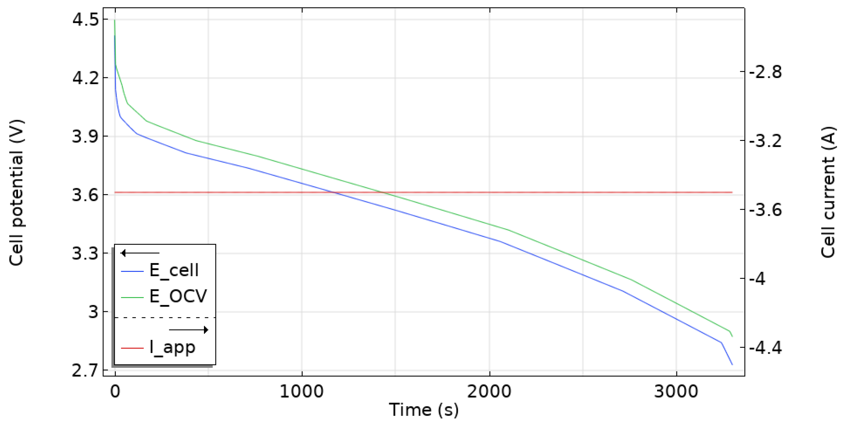
5.3. Battery Electrochemical and Thermal Behavior

The validated model has been used to investigate the electrochemical and thermal behavior of the battery in both off and on modes. Figure 6 shows the battery working potential and open circuit potential under 1 C discharge load. The battery terminal voltage deviates from the battery open circuit voltage during operation (charging/discharging) due to above polarization sources, including ohmic, activation, and concentration polarization [33].
Simulations were conducted for a single cell in off-mode and on-mode with varied discharge current rates at a temperature of 22.3 °C. Figure 7 compares inhomogeneous temperature contours and evolution obtained from simulations at 1 C (Figure 7a), 2 C (Figure 7b), and 3 C (Figure 7c). The maximum cell temperature rose to 27.6 °C, 35.5 °C, and 42.8 °C at 1 C, 2 C, and 3 C discharge, respectively. The higher temperature elevation at higher current rates could be explained by increased ohmic heat generating rates. While increasing the current rate raises the battery temperature, it has a low impact on the temperature gradient, whose values are 0.16, 0.4, and 0.39 under 1 C, 2 C, and 3 C discharge rates, respectively.
Finally, the hybrid BTMS’s potential impact was assessed at an ambient temperature. To this end, the battery was cooled using a passive cooling system, which sandwiched the battery between the aluminum-encased PCM-EG. The NiTi SMA was positioned between the holder and the heat sink made of aluminum. Figure 8 depicts the elevation of off-mode and on-mode battery surface temperatures at 3 C and 5 C discharge rates. The BTMS is switched to on-mode approximately when the battery temperature reaches 37 °C. The maximum temperature in the off-mode process at 3 C discharge is 43.346 °C, while it is 38.716 °C in the on-mode process. Similarly, at 5 C discharge, the maximum temperature is 48.808 °C in off-mode operation and 42.706 °C in on-mode operation. As a result, at 3 C and 5 C discharge rates, the battery temperature rises 4.63 °C and 6.102 °C less in on-mode discharge than in off-mode discharge, respectively, demonstrating the effectiveness of the passive thermal management system.
Figure 9 depicts the temperature counters of the BTMS and the battery at the end of an on-mode discharge at a rate of 5 C. It is clearly demonstrated that the designed BTMS keeps the temperature gradient below 0.71 °C.

6. Conclusions

Electric vehicles are ecologically friendly and energy efficient, addressing the needs of green values and energy conservation with the help of a clean energy power source, mainly a battery system. Temperature, on the other hand, has an adverse influence on the batteries’ reliability, safety, and efficiency. This study proposes a novel hybrid battery thermal management system comprised of NiTi SMA wires and PCM-EG to address the critical need for adaptive thermal management in battery applications. The NiTi SMA wire in the suggested design allows the BTMS to be turned on and off, allowing the PCM-EG to easily prevent battery overheating. A numerical simulation was used to assess the efficacy of the proposed BTMS. According to the findings, the smart BTMS demonstrated promising results in managing the battery maximum temperature while maintaining a uniform battery temperature distribution. This research aims to pave the way for a more straightforward and energy-efficient approach to battery temperature management in a variety of climates, which is critical for the adoption of electric vehicles and battery-based energy storage.

Author Contributions

Conceptualization, M.J., S.D. and M.A.; Data curation, M.J., S.D., M.A. and J.O.D.; Formal analysis, S.D. and M.A.; Funding acquisition, M.J.; Investigation, M.J.; Methodology, M.J., M.A.; Project administration, M.J.; Software, M.A., G.M. and J.O.D.; Supervision, S.D., M.A.; Validation, M.J., G.M., M.A.; Writing—original draft, M.J., G.M. and M.A.; Writing—review & editing, S.D., M.A. All authors have read and agreed to the published version of the manuscript.

Funding

This research received no external funding.

Institutional Review Board Statement

Not applicable.

Informed Consent Statement

Not applicable.

Data Availability Statement

Not applicable.

Acknowledgments

The authors gratefully thank the R&D Team at Birikim Batteries Company for their support.

Conflicts of Interest

The authors declare no conflict of interest.

References

  1. Zhang, L.; Chen, Q.; Wang, T. Effects of air cooling structure on cooling performance enhancement of prismatic lithium-ion battery packs based on coupled electrochemical-thermal model. Energy Sci. Eng. 2021, 9, 1450–1464. [Google Scholar] [CrossRef]
  2. Alipour, M.; Hassanpouryouzband, A.; Kizilel, R. Investigation of the Applicability of Helium-Based Cooling System for Li-Ion Batteries. Electrochem 2021, 2, 135–148. [Google Scholar] [CrossRef]
  3. Bandhauer, T.M.; Garimella, S.; Fuller, T.F. A Critical Review of Thermal Issues in Lithium-Ion Batteries. J. Electrochem. Soc. 2011, 158, R1. [Google Scholar] [CrossRef]
  4. Saw, L.H.; Ye, Y.; Tay, A.A.O. Integration issues of lithium-ion battery into electric vehicles battery pack. J. Clean. Prod. 2016, 113, 1032–1045. [Google Scholar] [CrossRef]
  5. Zhao, C.; Zhang, B.; Zheng, Y.; Huang, S.; Yan, T.; Liu, X. Hybrid Battery Thermal Management System in Electrical Vehicles: A Review. Energies 2020, 13, 6257. [Google Scholar] [CrossRef]
  6. Allcell, Lithium-Ion Battery Manufacturer|AllCell Technologies, LLC. Available online: https://www.allcelltech.com/ (accessed on 16 November 2021).
  7. Bai, F.; Chen, M.; Song, W.; Feng, Z.; Li, Y.; Ding, Y. Thermal management performances of PCM/water cooling-plate using for lithium-ion battery module based on non-uniform internal heat source. Appl. Therm. Eng. 2017, 126, 17–27. [Google Scholar] [CrossRef]
  8. Al-Hallaj, S.; Selman, J.R. Thermal modeling of secondary lithium batteries for electric vehicle/hybrid electric vehicle applications. J. Power Source 2002, 110, 341–348. [Google Scholar] [CrossRef]
  9. Goli, P.; Legedza, S.; Dhar, A.; Salgado, R.; Renteria, J.; Balandin, A.A. Graphene-enhanced hybrid phase change materials for thermal management of Li-ion batteries. J. Power Source 2014, 248, 37–43. [Google Scholar] [CrossRef] [Green Version]
  10. Wu, W.; Yang, X.; Zhang, G.; Ke, X.; Wang, Z.; Situ, W.; Li, X.; Zhang, J. An experimental study of thermal management system using copper mesh-enhanced composite phase change materials for power battery pack. Energy 2016, 113, 909–916. [Google Scholar] [CrossRef]
  11. Zhao, J.; Lv, P.; Rao, Z. Experimental study on the thermal management performance of phase change material coupled with heat pipe for cylindrical power battery pack. Exp. Therm. Fluid Sci. 2017, 82, 182–188. [Google Scholar] [CrossRef]
  12. Rangappa, R.; Rajoo, S. Effect of thermo-physical properties of cooling mass on hybrid cooling for lithium-ion battery pack using design of experiments. Int. J. Energy Environ. Eng. 2019, 10, 67–83. [Google Scholar] [CrossRef]
  13. Landini, S.; Leworthy, J.; O’Donovan, T.S. A Review of Phase Change Materials for the Thermal Management and Isothermalisation of Lithium-Ion Cells. J. Energy Storage 2019, 25, 100887. [Google Scholar] [CrossRef]
  14. Liu, C.; Xu, D.; Weng, J.; Zhou, S.; Li, W.; Wan, Y.; Jiang, S.; Zhou, D.; Wang, J.; Huang, Q. Phase Change Materials Application in Battery Thermal Management System: A Review. Materials 2020, 13, 4622. [Google Scholar] [CrossRef]
  15. Babapoor, A.; Azizi, M.; Karimi, G. Thermal management of a Li-ion battery using carbon fiber-PCM composites. Appl. Therm. Eng. 2015, 82, 281–290. [Google Scholar] [CrossRef]
  16. Jiang, G.; Huang, J.; Fu, Y.; Cao, M.; Liu, M. Thermal optimization of composite phase change material/expanded graphite for Li-ion battery thermal management. Appl. Therm. Eng. 2016, 108, 1119–1125. [Google Scholar] [CrossRef]
  17. Zou, D.; Ma, X.; Liu, X.; Zheng, P.; Hu, Y. Thermal performance enhancement of composite phase change materials (PCM) using graphene and carbon nanotubes as additives for the potential application in lithium-ion power battery. Int. J. Heat Mass Transf. 2018, 120, 33–41. [Google Scholar] [CrossRef]
  18. Sun, Z.; Fan, R.; Yan, F.; Zhou, T.; Zheng, N. Thermal management of the lithium-ion battery by the composite PCM-Fin structures. Int. J. Heat Mass Transf. 2019, 145, 118739. [Google Scholar] [CrossRef]
  19. Heyhat, M.M.; Mousavi, S.; Siavashi, M. Battery thermal management with thermal energy storage composites of PCM, metal foam, fin and nanoparticle. J. Energy Storage 2020, 28, 101235. [Google Scholar] [CrossRef]
  20. Qin, P.; Liao, M.; Zhang, D.; Liu, Y.; Sun, J.; Wang, Q. Experimental and numerical study on a novel hybrid battery thermal management system integrated forced-air convection and phase change material. Energy Convers. Manag. 2019, 195, 1371–1381. [Google Scholar] [CrossRef]
  21. Fathabadi, H. High thermal performance lithium-ion battery pack including hybrid active–passive thermal management system for using in hybrid/electric vehicles. Energy 2014, 70, 529–538. [Google Scholar] [CrossRef]
  22. Du, X.; Qian, Z.; Chen, Z.; Rao, Z. Experimental investigation on mini-channel cooling–based thermal management for Li-ion battery module under different cooling schemes. Int. J. Energy Res. 2018, 42, 2781–2788. [Google Scholar] [CrossRef]
  23. Naresh, G.; Kumar, T.P.; Aadhithyan, B.; Utkarsh, S.; Nithin, J.V. Transient thermal analysis of passive air-cooled battery-pack for various casing material. IOP Conf. Ser. Mater. Sci. Eng. 2020, 993, 012131. [Google Scholar] [CrossRef]
  24. Huang, W. On the selection of shape memory alloys for actuators. Mater. Des. 2002, 23, 11–19. [Google Scholar] [CrossRef]
  25. Hao, M.; Li, J.; Park, S.; Moura, S.; Dames, C. Efficient thermal management of Li-ion batteries with a passive interfacial thermal regulator based on a shape memory alloy. Nat. Energy 2018, 3, 899–906. [Google Scholar] [CrossRef]
  26. Joula, M.; Dilibal, S.; Owusu-Danquah, J. Smart adaptronic thermal management system designs for the Li-ion battery packs. In Proceedings of the 2021 IEEE International Conference on Mechatronics (ICM), Kashiwa, Japan, 7 March 2021. [Google Scholar] [CrossRef]
  27. Panasonic Industry, Lithium-Ion Battery Manufacturer. Available online: https://industrial.panasonic.com/pt/lithium-ion/models/NCR18650GA (accessed on 16 November 2021).
  28. Pra, F.; al Koussa, J.; Ludwig, S.; de Servi, C.M. Experimental and Numerical Investigation of the Thermal Performance of a Hybrid Battery Thermal Management System for an Electric Van. Batteries 2021, 7, 27. [Google Scholar] [CrossRef]
  29. Ng, B.; Coman, P.T.; Mustain, W.E.; White, R.E. Non-destructive parameter extraction for a reduced order lumped electrochemical-thermal model for simulating Li-ion full-cells. J. Power Source 2020, 445, 227296. [Google Scholar] [CrossRef]
  30. Ekström, H.; Fridholm, B.; Lindbergh, G. Comparison of lumped diffusion models for voltage prediction of a lithium-ion battery cell during dynamic loads. J. Power Source 2018, 402, 296–300. [Google Scholar] [CrossRef]
  31. Owusu-Danquah, J.; Saleeb, A.F.; Soudah, M.A. Cyclic pseudoelastic training and two-way shape memory behavior of a NiTi alloy with small irrecoverable plastic strains: Numerical modeling. Int. J. Solids Struct. 2021, 217, 178–192. [Google Scholar] [CrossRef]
  32. Saleeb, F.; Soudah, M.A.; Owusu-Danquah, J.S. Stabilization of the Cyclic Response of the Ni 49.9 Ti 50.1 Shape Memory Actuators under Thermomechanical Loads. J. Aerosp. Eng. 2021, 34, 04020099. [Google Scholar] [CrossRef]
  33. Coman, P.T.; Darcy, E.C.; Strangways, B.; White, R.E. A Reduced-Order Lumped Model for Li-Ion Battery Packs during Operation. J. Electrochem. Soc. 2021, 168, 100525. [Google Scholar] [CrossRef]
Figure 1. Battery charge and discharge experimental system.
Energies 15 04403 g001
Figure 2. Proposed hybrid BTMS design.
Energies 15 04403 g002
Figure 3. BTMS on and off modes.
Energies 15 04403 g003
Figure 4. Validation of the electrochemical and thermal behavior of the battery model using experimental measurements: (a) voltage validation, (b) temperature validation, (c) percent error (%) for simulated and measured battery voltage, and (d) percent error (%) for simulated and measured battery temperature.
Energies 15 04403 g004
Figure 5. The 20-cycle isobaric model result for the NiTi SMA.
Energies 15 04403 g005
Figure 6. Simulated battery terminal voltage (E_cell) and open circuit voltage (E_OCV) at 1 C discharge.
Energies 15 04403 g006
Figure 7. Off-mode battery temperature (°C) profiles at (a) 1 C, (b) 2 C, and (c) 3 C discharge rates.
Energies 15 04403 g007
Figure 8. On-mode versus off-mode temperature elevation at (a) 3 C and at (b) 5 C discharge rates.
Energies 15 04403 g008
Figure 9. (a) A volume and (b) a multiscale BTMS temperature profile at 5 C discharge.
Energies 15 04403 g009
Table 1. Test Protocol Table.
IDStep NameStep TimeVoltage (V)Current (A)Stop Current (A)
1Rest10 s
2CCCV_Chg4 h 30 min4.21.47500.0670
3Rest30 min
4CC_Dchg 2.53.5
5Rest30 min
6CCCV_Chg4 h 30 min4.21.47500.0670
7Rest30 min
8CC_Dchg 2.57.0
9Rest30 min
10CCCV_Chg4 h 30 min4.21.47500.0670
11Rest30 min
12CC_Dchg 2.510.0
13Rest30 min
14CCCV_Chg4 h 30 min3.521.47500.3500
15Rest30 min
16End
Table 2. Battery and PCM/EG Specifications [27,28].
ParametersValuesUnitsDetails
(a) Battery Specifications:
Battery ModelPanasonic SanyoNCR18650GA
Battery ChemistryLi-ionNCA
Cathode ChemistryLiNiCoAl-
Anode ChemistryCarbon-
Capacity3450mAh
Nominal Voltage3.6V
Charging4.20V
1475mA
CC-CV
Weight47.06gr
Energy Density224Wh/kg
Internal Resistance26.40mOhm
(b) PCM/EG Specifications:
PCM/EG Melting Point37°C
PCM/EG Density895kg/m3At room temperature
PCM/EG Thermal Conductivity10–25W/m/KHorizontal plane
Latent Heat160J/g
Specific Heat1.91J/g/°CSolid
Electrical Resistance0.4110−3 ΩmHorizontal plane
Table 3. Model parameters.
ParameterValueDescription
d b a t t (mm) 18.5Battery diameter
h b a t t (mm) 64.3Battery height
d t a b (mm) 9Positive tab diameter
h t a b (mm)1Positive tab height
C p (J⋅kg−1⋅K−1) 910Battery heat capacity
ρ (kg⋅m−3) 2735Battery density
η I R , 1 C , r e f (mV) 50Ohmic overpotential at 1 C and reference temperature
E a , I R (kj⋅mol−1) 40Activation energy for ohmic overpotential
J 0 , r e f (A ⋅m−2) 1Local current density at reference temperature
E a , J 0 (kj⋅mol−1) −60Activation energy for local current density
τ 0 (s)900Diffusion time constant at reference temperature
E a , τ 0 (kj⋅mol−1) 40Activation energy for diffusion time constant
k a n g (W⋅ m−1⋅K−1) 30.8Thermal conductivity, in plane
k r (W⋅m−1⋅K−1) 1.38Thermal conductivity, cross plane
h (W.⋅m−2⋅K−1) 8Heat transfer coefficient
T m (°C) 37Melting point
T (°C) 6Melting range
T 1 (°C) 32Initial temperature
T 2 (°C) 38Final temperature
C p , s (J⋅kg−1⋅K−1) 1910Heat capacity, solid
C p , l (J⋅kg−1⋅K−1) 2250Heat capacity, liquid
ρ s (kg⋅m3) 895Density at room temperature
L s l (J⋅kg−1) 160,000Latent heat
k s , k l (W⋅ m−1⋅K−1) 10–25Thermal conductivity (horizontal plane)
k s , k l (W⋅ m−1⋅K−1) 6–12Thermal conductivity (vertical direction)
Table 4. The fixed parameters.
ParametersUnitsValues
Elastic Constants
Elastic modulus, EGPa60
Poisson’s ratio, ν−W0.3
Inelastic Constants
No. of mechanisms-6
n-5
μMPa.s1 × 105
κMPa20
κ(b), b = 3MPa1E21
κ(b), b = 5MPa50
κ(b), b = 6MPa72
β(b), b = 1 to 6-1, 1, 10, 10, 1, 2.5
H(b), b = 1 to 3MPa300 × 103, 300 × 103, 200
H(b), b = 4 to 6MPa45 × 103, 2 × 10³, 600
Table 5. Temperature-dependent parameters.
Temperature (°C)κ(b), b = 1, 2κ(b), b = 4
150.01100
350.0110
6510010
Publisher’s Note: MDPI stays neutral with regard to jurisdictional claims in published maps and institutional affiliations.

