Article

Numerical Investigation on Backward-Injection Film Cooling with Upstream Ramps

1
College of Energy and Power Engineering, Nanjing University of Aeronautics and Astronautics, Nanjing 210016, China
2
College of Civil Aviation, Nanjing University of Aeronautics and Astronautics, Nanjing 210016, China
3
School of Chemical and Process Engineering, University of Leeds, Leeds LS2 9JT, UK
*
Author to whom correspondence should be addressed.
Energies 2022, 15(12), 4415; https://doi.org/10.3390/en15124415
Submission received: 11 May 2022 / Revised: 7 June 2022 / Accepted: 11 June 2022 / Published: 17 June 2022

Abstract

:
The present study investigates the effects of upstream ramps on a backward-injection film cooling over a flat surface. Two ramp structures, referred to as a straight-wedge-shaped ramp (SWR) and sand-dune-shaped ramp (SDR), are considered under a series of blowing ratios ranging from M = 0.5 to M = 1.5. Regarding the backward injection, the key mechanism of upstream ramps on film cooling enhancement is suggested to be the enlargement of the horizontal scale of the separate wake vortices and the reduction of their normal dimension. When compared to the SDR, the SWR modifies the backward coolant injection well, such that a larger volume of coolant is suctioned and concentrated in the near-field region at the film-hole trailing edge. As a consequence, the SWR demonstrates a more pronounced enhancement in film cooling than the SDR in the backward-injection process, which is the opposite of the result for the forward-injection scheme. For the SWR, the backward injection provides a better film cooling effectiveness than the forward injection, regardless of blowing ratios. However, for the SDR, the backward injection could show a superior effect to the forward injection on film cooling enhancement, when the blowing ratio is beyond a critical blowing ratio. In the present SDR situation, the critical blowing ratio is identified to be M = 1.0.

1. Introduction

Film cooling is well known as an indispensable “external” cooling scheme as applied to the thermal protection of hot-section components in the gas turbines. Benefiting from the development of advanced film cooling technologies, the overall cooling effectiveness has been increased progressively, which allows the gas turbines to operate reliably at a higher and higher inlet temperature. For the next-generation gas turbine engines, the turbine inlet temperature will be further prompted, as such, pursuing increasingly effective film cooling schemes is still a necessity.
According to the fundamental jet-in-crossflow dynamics, the key mechanism for enhancing film cooling effectiveness lies in the mitigation of counter-rotating vortex pair (CVP) or kidney vortices in the jet, which contribute to a greater lateral spreading but a weaker normal penetration of the coolant jet [1,2]. Apparently, the mutual interaction between coolant jets and the mainstream can be controlled by altering either the coolant-jet injection or the oncoming mainstream boundary layer flow. Following this acceptance, many passive strategies (such as compound-angle injection [3,4,5], shaped holes [6,7,8,9], shallow trenches [10,11,12], upstream ramps [13,14,15], etc.) for the film cooling enhancement are developed continuously.
The upstream ramp is a promising device that controls the oncoming mainstream upstream of the coolant jet injection. Na and Shin [13] numerically assessed the potential of upstream ramps for improving cylindrical-hole film cooling. Their results illustrated that the lateral diffusion of cooling jets is enhanced significantly by the entrainment of the recirculating flow behind the ramp. Consequently, better uniformity of film cooling in the spanwise or lateral direction was achieved along with a higher laterally averaged adiabatic film cooling effectiveness. Barigozzi et al. [14,15] experimentally studied the aerodynamic and thermal performances of flat-plate film cooling in the presence of an upstream ramp at several blowing ratios ranging from M = 0.3 to M = 1.0. It was determined that the upstream ramp modifies the discharge coefficients of coolant injection, but aerodynamic losses were also promoted due to the flow separation of the mainstream. Chen et al. [16] experimentally tested the film cooling effectiveness for four upstream ramps with different ramp angles (or heights) under five blowing ratios ranging between M = 0.4 and M = 1.4. Their results indicate that a larger-angle ramp at high blowing ratios generally provides more favorable film layer coverage. Rallabandi et al. [17] experimentally studied multi-parameter influences of ramp geometry (such as width, height, and upstream location) on the film cooling performance. Their results illustrated that a closer coolant discharge location relative to the upstream ramp generally yields more favorable film cooling enhancement. However, when the coolant injection was located at the reattachment zone of the oncoming mainstream, it resulted in the upstream ramp having a negative impact on film cooling.
More recently, the contoured shape and novel layout of upstream ramps have received much attention. For instance, Abdala and Elwekeel [18] and Abdala et al. [19] presented and numerically assessed the concept of curved ramps. It was illustrated that a properly curved ramp could produce higher film cooling effectiveness but a smaller heat transfer coefficient compared to the conventional normal ramp. Hammami et al. [20] presented a novel design concept wherein the upstream pyramid was located in the exact middle between two adjacent holes. A numerical evaluation identified that this ramp geometry could be an effective compromise between pressure loss and film cooling effectiveness. Zhang et al. [21] numerically studied the rectangular-hole film cooling in the presence of an uneven upstream ramp (with unevenly spanwise distributed height) and found that an anti-CVP pair could form using a specially designed uneven upstream ramp with a reduced middle height, resulting in greater improvement to the film cooling performance. Zhou and Hu [22] proposed a novel sand-dune-shaped ramp that had a favorable aerodynamic contour with respect to the oncoming airflow. By using this specifically contoured ramp, an additional vortex pair with opposite rotation directions to the kidney vortex pair appeared downstream from the ramp horns, significantly enhancing film cooling effectiveness. Later, Zhou and Hu [23] and Zhou et al. [24] further developed another novel film cooling configuration, designated BDSIC (Barchan-dune-shaped injection compound), by incorporating the coolant injection modification into the sand-dune-shaped ramp. Zhang et al. [25] numerically evaluated the effect of sand-dune-shaped ramp height on film cooling effectiveness, wherein three heights (0.25, 0.5, and 0.75 D; D is the film cooling hole diameter) were taken into consideration. It was found that a relatively optimal ramp height is 0.5 D at small blowing ratios, while at large blowing ratios, a large ramp height was responsible for producing the most film cooling enhancement. For a fixed ramp height of 0.5 D, Zhang et al. [26] further performed an experimental and numerical study to comparatively investigate the sand-dune-shaped ramp film cooling with respect to a normal straight-wedge-shaped ramp, identifying that the sand-dune-shaped ramp plays a more pronounced role in film cooling enhancement. They also studied the coupled effects of shaped holes (such as the fan-shaped hole and crater-shaped hole) and sand-dune-shaped upstream ramps on film cooling performance [27]. It was illustrated that the integrity of shaped film cooling holes and the sand-dune-shaped upstream ramp provide a dramatic film cooling improvement, especially under high blowing ratios.
From the aforementioned literature, it is exactly sure that most of the previous investigations on upstream ramp film cooling were conducted for the forward-injection situations. In actuality, the coolant injection orientation is also a paramount factor that affects the mutual interaction between coolant jets and primary flow, and subsequently the film cooling performance. The backward injection, an opposite scheme to forward injection, was illustrated by Li et al. [28] and Subbuswamy et al. [29,30] to own a unique interaction feature of jet-in-crossflow, leading to a better jet spreading in the lateral direction but a worse jet spreading along the streamwise direction on the whole. Because backward coolant injection could provide a uniform film cooling in the lateral direction relative to the forward coolant injection, it was suggested to be a possible scheme for weakening the thermal gradients. For conventional cylindrical-hole film cooling, the backward injection was clearly identified by many researchers (Park et al. [31], Singh et al. [32], Prenter et al. [33], Shi et al. [34]) to be advantageous to forward injection in terms of average film cooling effectiveness and comparable net heat flux reduction. However, it remains unclear whether backward injection can achieve the same results in shaped-hole cooling as it does in cylindrical-hole cooling. Chen et al. [35] and Li et al. [36] investigated the coolant injection schemes (forward injection and backward injection) for both the cylindrical-hole and the fan-shaped-hole film cooling. Their results demonstrate that the backward-injection scheme greatly improves the film cooling effectiveness for the cylindrical holes at higher blowing ratios, but with a fan-shaped hole, it slightly reduces the film cooling effectiveness relative to the forward-injection scheme. Zhao et al. [37] numerically investigated the effect of coolant injection on the adiabatic film cooling effectiveness of different holes (cylindrical hole, expansion-shaped hole, and fan-shaped hole) under a range of blowing ratios from M = 0.25 to M = 2.0. From the computed results, they identified the critical blowing ratios for different film cooling hole shapes, i.e., the blowing ratio above which backward injection yields higher film cooling effectiveness than forward injection. It was found that the critical blowing ratio is influenced by the hole shape, with a critical M of 0.75 for the expansion-shaped hole and 1.25 for the fan-shaped hole compared to critical M = 0.5 for a cylindrical hole. Jeong and Park [38] numerically assessed the effect of inlet compound angle on backward injection film cooling. Singh et al. [39] performed a large eddy simulation to assess the cylindrical-hole and laid-back fan-shaped-hole film cooling with backward injection, with a fixed blowing ratio of M = 1.0 and a density ratio of DR = 2.42. In terms of laterally averaged adiabatic film cooling effectiveness, backward injection in cylindrical-hole film cooling achieved approximately a 100% increase in the near-hole region and a 33% increase in the far-downstream region compared to forward injection. In the laid-back fan-shaped-hole film cooling, backward injection only achieved a roughly 42% increase in the near-hole region. Zheng et al. [40] numerically assessed the roles of upstream ramps on the backward-injection film cooling, wherein the backward injection angles and upstream ramp locations were considered. The dual-aspect effect of the downward vortex and coolant entrainment was identified to dominate the backward-injection film cooling with upstream ramp incorporation, contributing to enhanced film cooling. Ali Kouchih et al. [41] performed a numerical study comparing the effects of an upstream Barchan-dune-shaped ramp on forward-injection and backward-injection film cooling. Backward injection incorporating an upstream Barchan-dune-shaped ramp yielded a greater spatially averaged film cooling effectiveness than the corresponding forward injection case at a high blowing ratio (i.e., M = 1.5), whereas at a small blowing ratio (i.e., M = 0.5), the forward injection with an upstream Barchan-dune-shaped ramp was more favorable.
As the upstream ramps generally act as a vortex generator or two-dimensional (2D) roughness, their effects on the turbulent boundary layer were illustrated as well by the following research. Choi et al. [42] investigated the spatially developing turbulent boundary layers over rod- and cuboid-roughened walls under different roughness heights. The results found that the magnitude of the Reynolds stresses in the outer layer increases with the increase in the roughness height to boundary layer thickness ratio. Mori et al. [43] numerically studied the effect of uniform blowing on the turbulent channel flow over a 2D irregular rough wall. Their results indicated that the drag reduction effect of uniform blowing on the 2D rough wall is similar to that for a smooth wall, and the uniform blowing makes the rough wall aerodynamically smoother due to the reduction of pressure drag. Hamed et al. [44] carried out an experiment to study the blowing effects on the turbulent boundary layer over 2D k-type roughness. They found that the localized blowing results in an increase in the time-averaged streamwise velocity but a reduction in the maximum streamwise-averaged Reynolds shear stress and turbulent kinetic energy. Furthermore, Djenidi et al. [45,46] experimentally investigated the wall suction effects on the rough-wall turbulent boundary layer. It was seen from the velocity spectra contour maps that the suction decreases the energy at all scales of motion across the boundary layer. However, they found that the suction neither leads to relaminarization of the boundary layer nor significantly changes the turbulence structure of the boundary layer.
The research on the backward-injection film cooling with upstream-ramp incorporation are insufficient. As the backward coolant injection changes jet-in-crossflow dynamics, it produces noticeable differences in film cooling relative to the forward coolant injection. The main objective of the present study is to identify the effects of two ramp structures (straight-wedge-shaped ramp (SWR) and sand-dune-shaped ramp (SDR)) on backward-injection film cooling and to illustrate the detailed jet-in-crossflow dynamics. Since the SDR is a typical discrete ramp and the SWR is a typical continuous ramp, the comparative study between the two configurations would be representative. In addition, in combination with previous studies on forward injection film cooling [25,26,27], the distinct influencing roles of upstream ramp structure on backward-injection film cooling (denoted as BI) are illustrated in comparison with forward-injection situations (denoted as FI).

2. Description of Research Procedures

The present study follows our previous works on upstream-ramp film cooling with forward injection [25,26,27]. The computational methodologies adopted here are the same as those in the above-mentioned references. For the sake of simplicity and brevity, a brief description of the employed methods is provided here; further details can be found in the indicated references.

2.1. Computational Model

The numerical model is displayed in Figure 1. The computational model consists of three parts, including a coolant plenum, film hole, and mainstream channel. To account for the periodicity, the spanwise size of the computational domain is selected as one hole-to-hole pitch (3 D). For the purpose of reducing computational grids, the streamwise and normal sizes of the mainstream passage are reduced. The film cooling hole is placed at 15 D downstream of the mainstream passage entrance to avoid the direct influence of the inlet boundary-layer flow on the jet-in-crossflow interaction. Furthermore, the mainstream outlet is set at 35 D downstream of the film hole to avoid the possible backflow affecting the prediction accuracy. The setting of the corresponding coordinate system is shown in Figure 1.
In the present study, the backward injection angle (α) of coolant discharge is selected as −35° with respect to the mainstream flow direction. Two types of upstream ramps, the sand-dune-shaped ramp (SDR) and straight-wedge-shaped ramp (SWR), are comparatively investigated. Each ramp has the same geometry as in reference [26]. The contoured shape of the SDR depends on many geometric parameters, including the ramp height (Hr), total length from leading edge to trailing edge (Lr), front-wedge length from leading edge to central apex (Lf), middle-slope length from central apex to slope edge (Lm), and horn-spacing (W) that encloses the film cooling hole, as displayed in Figure 2a and Table 1. When regarding the incorporation of film cooling holes, the distance between the central slope edge and film-hole center is defined as L1. For the SWR, as seen in Figure 2b and Table 1, the height is kept the same as for the SDR, and the length (Lr) is equal to the front-body length (the sum of Lf and Lm) of the SDR. The distance between the rear step of SWR and the film-hole center is the same as L1 for the SDR. Moreover, the SDR denotes a typical discrete ramp, but the SWR denotes a typical continuous ramp. The film cooling mechanisms of the two configurations are illustrated by comparing with the baseline case without an upstream ramp.

2.2. Boundary Conditions

Both mainstream and cooling air are treated as ideal gases, with temperature-dependent thermal properties considered. As seen in Table 2, the mainstream entrance is set as velocity inlet with an inflow velocity (u) of 25 m/s and a temperature (T) of 360 K. Furthermore, a modification of the inflow velocity profile is adopted with the use of the 1/7th power law approach, referring to Zhou and Hu [22], where the turbulent boundary layer has a thickness of δ99 ≈ 1.4 D, a momentum thickness of θ ≈ 0.15 D, and a shape factor of H12 = 1.32. The outlet pressure is applied at the mixing flow outlet, with an imposed constant pressure pout = 101,325 Pa; other variables are considered upwind. The coolant entrance is set as mass flow inlet with an inlet temperature of 300 K. Consequently, the density ratio of cooling air to mainstream (DR) is around 1.2. This study considers a series of blowing ratios ranging from M = 0.5 to M = 1.5. The blowing ratio is defined as:
M = ρ c u c ρ u
where ρc and uc are density and bulk-averaged velocity, respectively, of the coolant jet at the film-hole exit. The spanwise side planes are set as periodic boundary conditions, and the top wall of the mainstream channel utilizes a symmetric boundary condition to impose a slip velocity on the plane, thus avoiding the possible generation of channel vortices. For solid surfaces, the no-slip velocity and adiabatic thermal boundary conditions are applied. According to the mainstream temperature (T), coolant temperature (Tc), and adiabatic wall temperature (Taw), the adiabatic film cooling effectiveness (ηad) is defined as Equation (2).
η ad = T T aw T T c

2.3. Computational Scheme

The numerical simulation is conducted with the use of a common CFD tool, ANSYS-Fluent [47], through the solving of three-dimensional steady turbulent Reynolds-averaged Navier-Stokes (RANS) equations. The governing equations are presented as follows [47].
ρ ¯ t + x i ρ u i ¯ + ρ u i ¯ = 0
t ρ u i ¯ + ρ u i ¯ + x i ρ u i ¯ u j ¯ + u i ¯ ρ u j ¯ = p ¯ x i + x j τ ij ¯ u j ¯ ρ u i ¯ ρ ¯ u i u j ¯ ρ u i u j ¯
t c p ρ ¯ T ¯ + c p ρ T ¯ + x j c p ρ ¯ T ¯ u j ¯ + c p T ¯ ρ u j ¯
= p ¯ t +   u j ¯ p ¯ x j +   u j p x j ¯ + x j k T ¯ x j c p ρ ¯ T u j ¯ c p ρ T u j ¯ u j ¯ c p ρ T ¯ + Φ ¯
where Φ ¯ = τ ij ¯ u i ¯ x j + τ ij u i x j ¯ , τ ij ¯ = μ u i ¯ x j + u j ¯ x i 2 3 δ ij u k ¯ x k . In the current study, all unsteady terms need to be removed for the steady simulation. Moreover, in the RANS equations, the Reynolds stress term ρ ¯ u i u j ¯ , and the turbulence diffusion term ρ ¯ T u j ¯ could not be solved directly. Therefore, the RANS equations should be closed by the Boussinesq eddy viscosity assumption and the turbulence model.
ρ ¯ u i u j ¯ = 2 μ T S ij - 2 3 δ ij μ t u k x k + ρ k
ρ ¯ T u j ¯ = μ t Pr t T x j
where k is the turbulence kinetic energy   k = u i u i ¯ / 2 , S ij = 1 2 ( u i x j + u j x i ) , Prt is the turbulent Prandtl number.
When considering the turbulence enclosure, the realizable k-ε eddy viscosity turbulent model is selected, as it has been reported by many researchers to be a proper two-equation turbulence model in the prediction of film cooling performance (e.g., Ely and Jubran [48], Foroutan and Yavuzkurt [49], Zhu et al. [50], Hang et al. [51]). This turbulence model is also validated in our previous works [25,26,27]. Figure 3 presents the validation of the computational scheme by comparing it with the experimental results of Zhou et al. [22] (M = 0.4). The results indicate that the realizable k-ε turbulent model produces a more favorable prediction of the film cooling with an upstream ramp relative to the other models. The deviations between the numerical results and the experimental results are within 5% in most areas, and the maximum deviation is about 13%. Based on the works in Refs [13,20,21,48,49,50,51] and the present validation, the realizable k-ε turbulent model is finally selected in the current study.
The transport equations of the realizable k-ε turbulent model are expressed as follows:
t ρ k + x j ρ k u j = x j μ + μ t σ k k x j + G k + G b - ρ ε - Y M + S k
t ρ ε + x j ρ ε u j = x j μ + μ t σ ε ε x j + ρ C 1 S ε - ρ C 2 ε 2 k + ν ε + C 1 ε ε k C 3 ε G b + S ε
where G k = - ρ u i u j ¯ u j x i , G b = g i μ t ρ Pr t ρ x i , and gi is the gravity component in the i direction. Y M = 2 ρ ε k a 2 , and a denotes the acoustic velocity.   C 1 = max 0 . 43 , η η + 5 ,   η = 2 S ij S ij k ε ; C 1 ε = 1 . 44 ,   C 2 = 1.9 ,   σ k = 1.0 ,   σ ε = 1.2 ; C is a constant. Sk and Sε are the source terms.
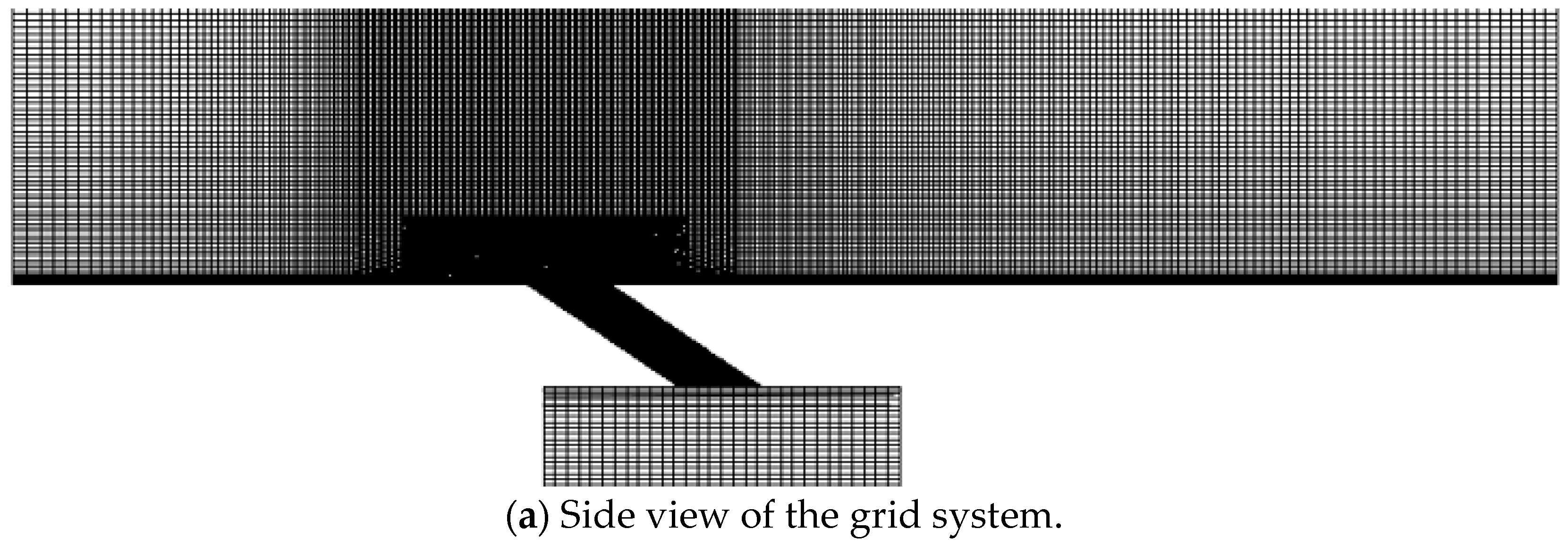
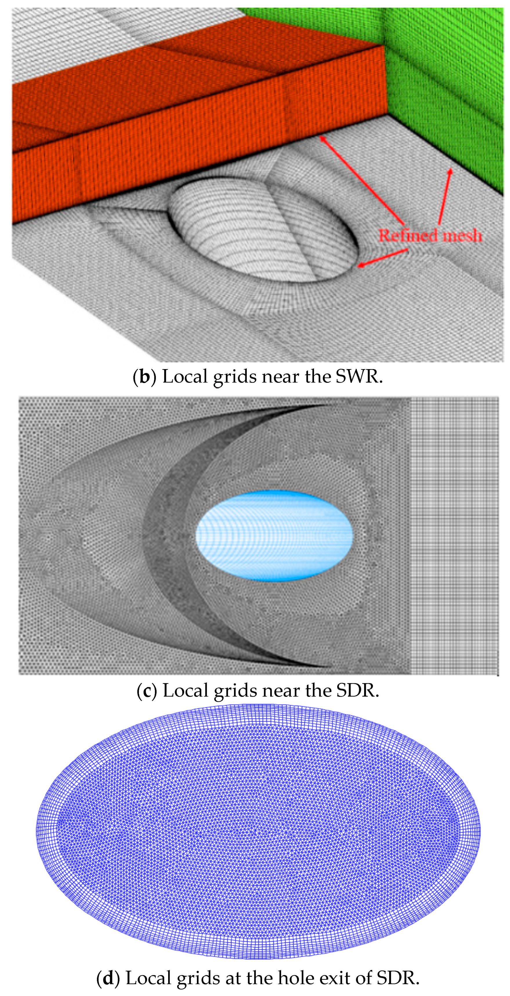
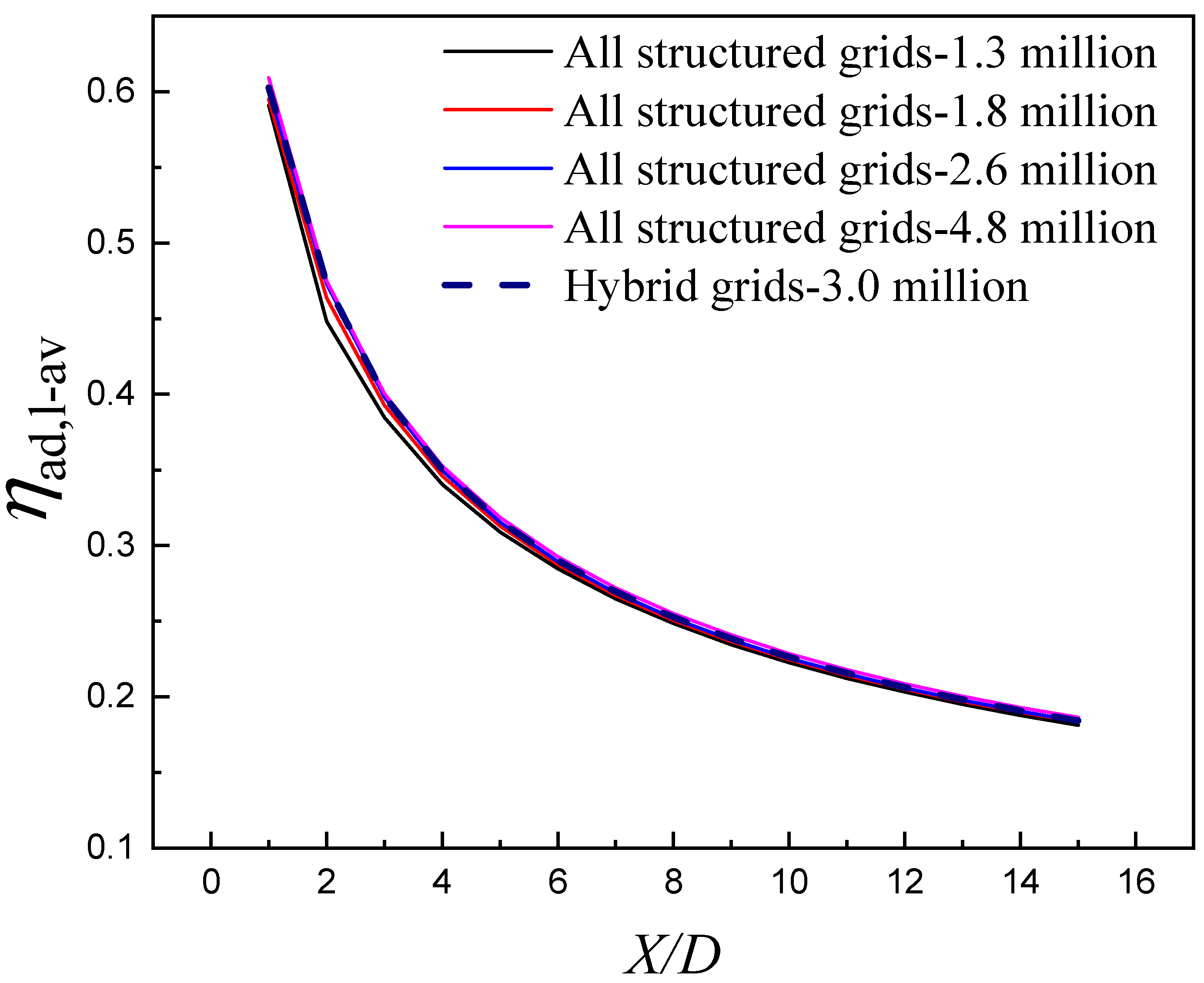
For the computational meshes, a mixed-grids generation strategy is adopted (Figure 4) by applying unstructured grids near the SDR and structured grids in the other regions. The near-wall-mesh refinement is carefully designed (including the film hole of the SDR) to ensure that the dimensionless distances of the first layer grids (z+) meet the requirement of the enhanced wall treatment, where z+ = (Δz * uτ)/ν; Δz is the height of the first-layer grids, uτ is the shear velocity of the wall, and ν denotes the viscosity of the fluid. Specifically, the boundary-layer grids are set as 15 layers with a first-layer height of 0.003 mm and a growth ratio of 1.1. To make sure that the numerical solution is grid independent, a grid-independent test is conducted in advance wherein a set of simple grid systems are designed to identify the grid sensitivity in a grid number range from 1.1 million to 4.8 million. This grid-independent test established a reasonable computational mesh construction of approximately 2.3 million grids, with the corresponding wall neighboring-cell dimensionless distances (z+) all roughly unity. Figure 5 presents the grid-independent test for the SWR case under M = 0.5. A hybrid grid system, generated in the same manner as that in the SDR case, is also adopted to illustrate the influence of the grid types on the prediction accuracy of the numerical simulation. The numerical results of the hybrid grid system are highly consistent with those of the all-structured grid systems, when the grid system meets the requirement of a grid-independent solution.
The RANS-based numerical methodology is commonly classical content. In the present study, the spatial discretization of the convective terms in the Reynolds-averaged Navier-Stokes equations utilizes the second-order upwind scheme. The pressure-velocity coupling is solved using the SIMPLEC algorithm. Convergence is considered to be reached when the root-mean-square residuals of concerned variables (including the equations’ residual and monitored temperatures on the plate surface) fall below 1.0 × 10⁻⁵.

3. Results and Discussions

3.1. Fundamental Dynamics of Jet-in-Crossflow

Film cooling performance is tightly associated with the features of jet-in-crossflow. This section describes the computed flow fields of the backward-injection film cooling under a typical blowing ratio of M = 1.0.
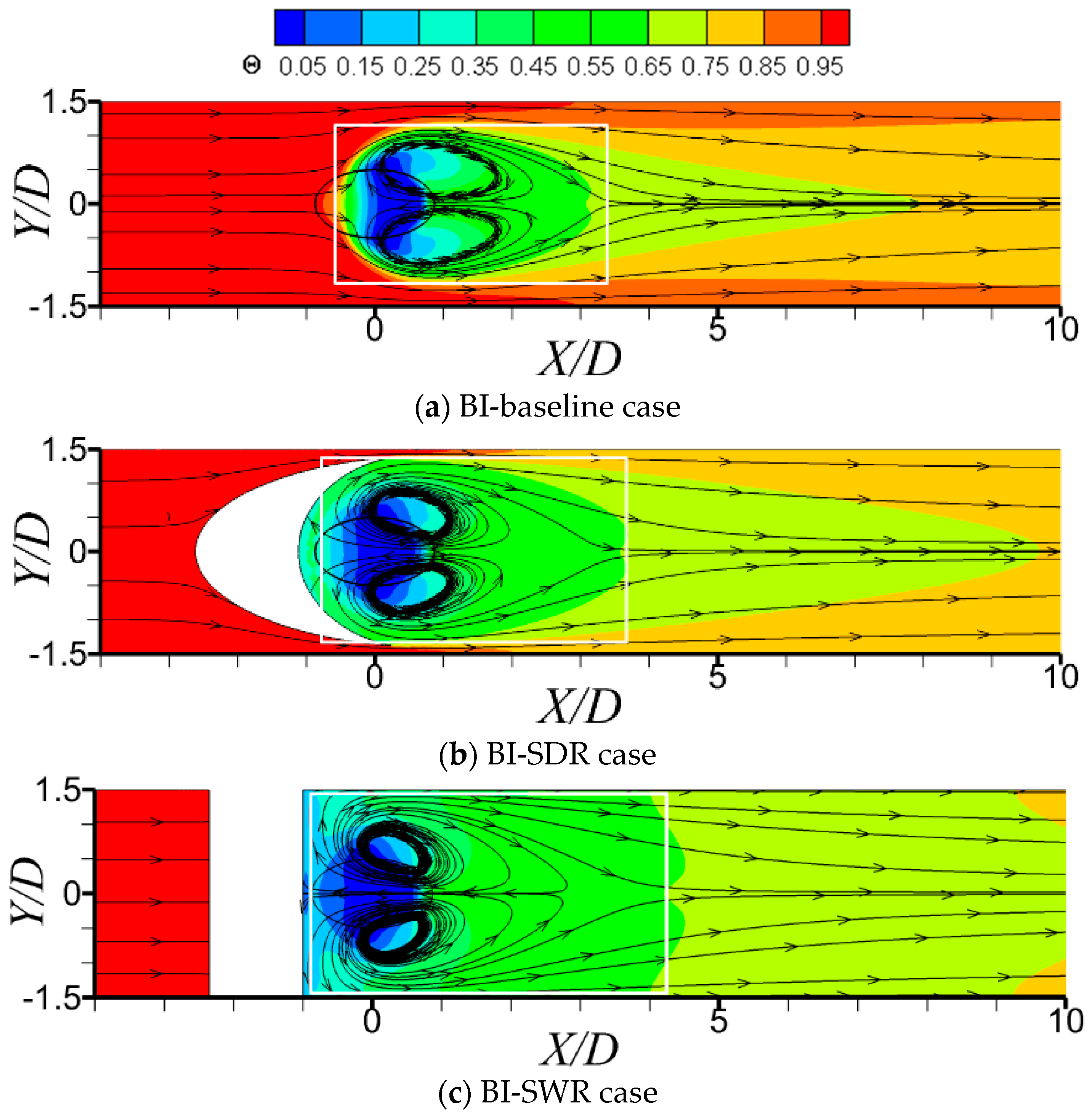
Figure 6 demonstrates the local streamlines nearby a film cooling hole in the backward injection situation, colored by the dimensionless temperature Θ (defined as Θ = T T c T T c ). For backward injection, as the coolant jet is ejected against the mainstream flow direction, it is forced to deflect in the consequent direction of the primary flow upon the impact of the oncoming primary flow. Owing to this strong flow turning of the jet, a flow separation happens behind the coolant jet. Meanwhile, as the coolant jet is hardly ejected from the leading edge of the film-hole against the upstream oncoming flow, it should find its way out of the film-hole exit from the lateral sides. Because of this unique interaction feature in the backward-injection film cooling, complicated separate wake vortices are generated in the near field of the film cooling hole, preventing the formation of kidney vortices that generally appear in the forward-injection situations. For the two cases with upstream ramps, although the near-field flow details have been changed to some extent, the dominant vortex structure (separate wake vortices) in the BI-baseline case still appears in the flow fields of the BI-SDR case and BI-SWR case. With an upstream ramp installed ahead of the film cooling hole, the impact of the oncoming primary flow on the coolant jet injection is effectively alleviated, and the coolant jets are allowed to diffuse more fully in the near field of the film cooling hole as a result. The lateral flow turning of the coolant jet in the two ramp cases is mainly forced by the blocking effect of the rear faces of the ramps, which is different from the BI-baseline case.
Figure 7 presents the static gauge pressure contours on a horizontal plane above the film-cooled surface (Z/D = 0.125), characterized by a dimensionless pressure coefficient Cp (Cp = (ppo)/0.5ρu). As seen in Figure 7a, for the baseline case without the upstream ramp, a significant pressure increase occurs in the front of the film cooling hole, and a negative static gauge pressure zone forms behind the film cooling hole. Accordingly, the coolant jet injection from the leading zone of the film cooling hole (relative to the coolant jet injection direction) is significantly blocked by the oncoming primary flow. With the use of upstream ramps, as the oncoming primary flow is deflected upward by the ramp, a pressure reduction forms behind the ramp due to the boundary layer flow separation effect of the oncoming mainstream, as demonstrated in Figure 7b,c. The significant pressure increase occurs near the front edge of ramps, far from the leading edge of the film cooling hole.
Figure 8 presents the dimensionless temperature contours and streamlines of the hole-centerline plane. In the absence of upstream ramps, the oncoming mainstream can encroach slightly into the leading zone of the film cooling hole. As a result, the coolant jet injection is more concentrated near the trailing zone of the film cooling hole, which aggravates the normal penetration of the coolant jet into the mainstream. When upstream ramps are employed, this encroachment is eliminated, as the regions of pressure increase are moved to the front edge of ramps. Because of this, more coolant is ejected from the leading zone of the film cooling hole, and the local coolant jet penetration at the trailing zone of the film cooling hole is subsequently weakened compared to the baseline case, especially for the SWR case. Furthermore, the normal dimension of the separation wake vortices is dramatically reduced. Figure 9 shows the dimensionless normal injection velocity contours at the hole exit, which also confirms that the presence of the upstream ramps improves the normal velocity distribution at the film-hole exit. Again, this is particularly pronounced for the SWR case.
Figure 10 shows the dimensionless temperature contours and streamlines of the horizontal plane immediately above the film-cooled surface (Z/D = 0.125). It can vividly be seen that a pair of separate wake vortices forms near the trailing edge of the film-hole on the horizontal plane, due to the shearing of crossflow with the obstructing coolant jet. By incorporating the separate vortex of the coolant jet, the near flow field of the film cooling hole is characterized by the complex chaotic flow. Attributed to the wake vortices, a large volume of coolant is suctioned and concentrated in the near-field region at the film-hole trailing edge. Therefore, the lateral spreading of the coolant jet is enhanced, producing better film layer coverage immediately downstream of the film cooling hole. Figure 10 confirms that the presence of upstream ramps does not introduce a significant change in inherent flow structures in the BI-baseline case, but it does modify the interaction of the coolant jet with the oncoming primary flow. Compared to Figure 10a, with the use of upstream ramps, the impact of the oncoming primary flow on the coolant jet injection is effectively alleviated, resulting in more coolant being directed toward the rear face of the upstream ramp. Consequently, the separate wake vortex cores are moved toward the ramp accordingly. It is also found that the horizontal scale (as shown in the white box) of the separate wake vortex is improved in the presence of upstream ramps, as the lateral spreading of the coolant jet is enhanced when the jet impinges on the rear face of the ramps. By comparing Figure 10b,c, the SWR is seen to be more favorably influenced by the backward-injection film cooling scheme. The enlargement of the horizontal scale of the separate wake vortices is more significant in the SWR case than in the SDR case, with respect to the baseline case.
Figure 11 presents the local streamlines and dimensionless temperature contours on three streamwise planes. For the BI cases, the separate wake vortex is the dominant flow structure in the flow fields of backward-injection film cooling, which results in an upwash effect near the hole-centerline region (Y/D = 0). The upwash effect is gradually aggravated with the increase in streamwise distance. With the presence of upstream ramps, the situation is improved, although the size of the separate wake vortex becomes bigger relative to the baseline case at X/D = 2. For the BI-SDR case, its upwash effect changes little with the increase in streamwise distance. While for the BI-SWR case, it clearly shows that the upwash of the coolant jet is gradually weakened with the increase in streamwise distance.
As seen in Figure 10 and Figure 11, therefore, the key mechanism of upstream ramps on backward-injection film cooling enhancement is suggested to be the enlargement of the horizontal scale of the separate wake vortices and the reduction of the normal dimension of the separate wake vortices.

3.2. Adiabatic Film Cooling Effectiveness Distributions

In this section, the distributions of backward-injection film cooling effectiveness for both ramps, under three typical blowing ratios, are presented for comparison and illustration.
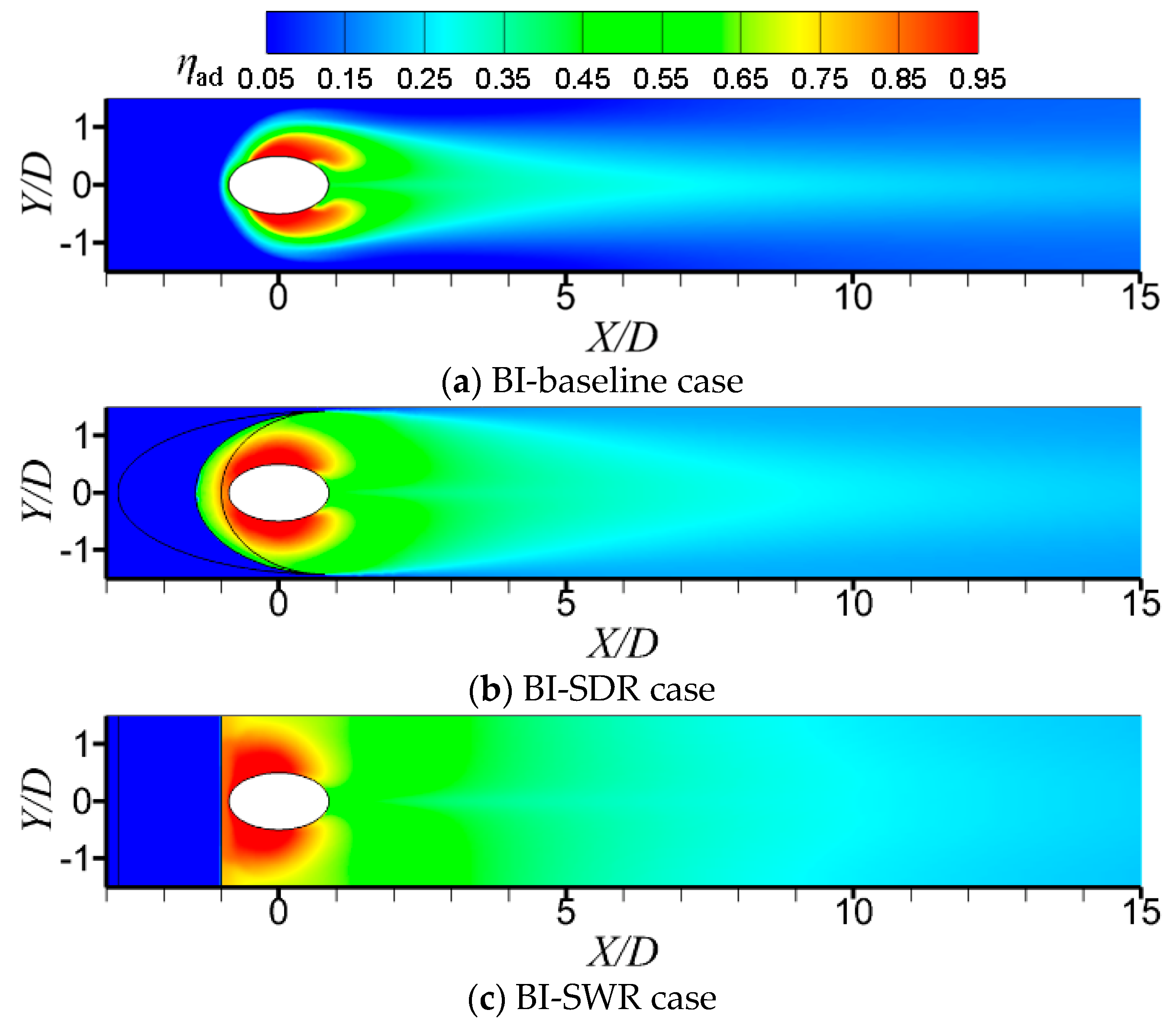
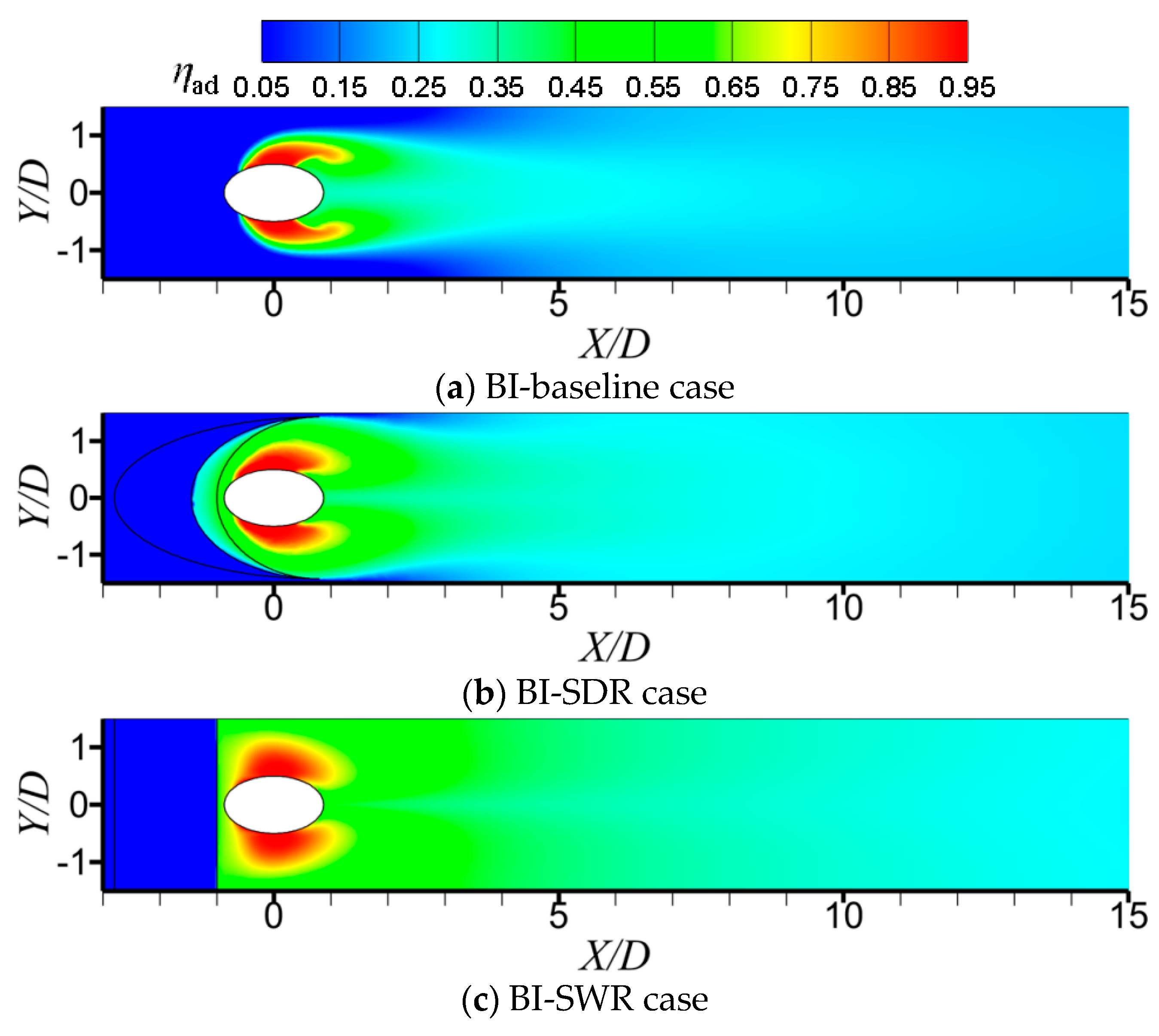
Figure 12, Figure 13 and Figure 14 display the local adiabatic film cooling effectiveness (ηad) distributions in the BI case, under M = 0.5, 1.0, and 1.5, respectively. For the BI-baseline case, due to the generation of the separate wake vortex, a high ηad region is formed immediately behind the film hole. However, there is still a large area on both sides of the film hole that is not covered by cooling film. This situation is improved with the use of an upstream ramp. Complying with the aforementioned flow physics in the BI cases, it is found that the presence of an upstream ramp significantly increases the lateral film coverage of backward-injection film cooling, which is similar to the previous findings in the forward-injection situations [26]. Furthermore, in the presence of the upstream ramp, the cooling jet directly impinges on the rear face of the upstream ramp and then “washes” the adjacent plate surface, which results in the ηad on the region immediately behind the ramp being extremely high. By comparing the BI-SDR and BI-SWR, it can be seen that the SWR produces better film cooling than the SDR under the given blowing ratios, which is distinct from the previous findings in the forward-injection situations [26].

3.3. Different Roles of Upstream Ramps on Film Cooling Enhancement

In this section, the influencing roles of two upstream ramps on the backward-injection film cooling are discussed. In addition, they are comparatively illustrated with respect to the forward-injection situations [26].
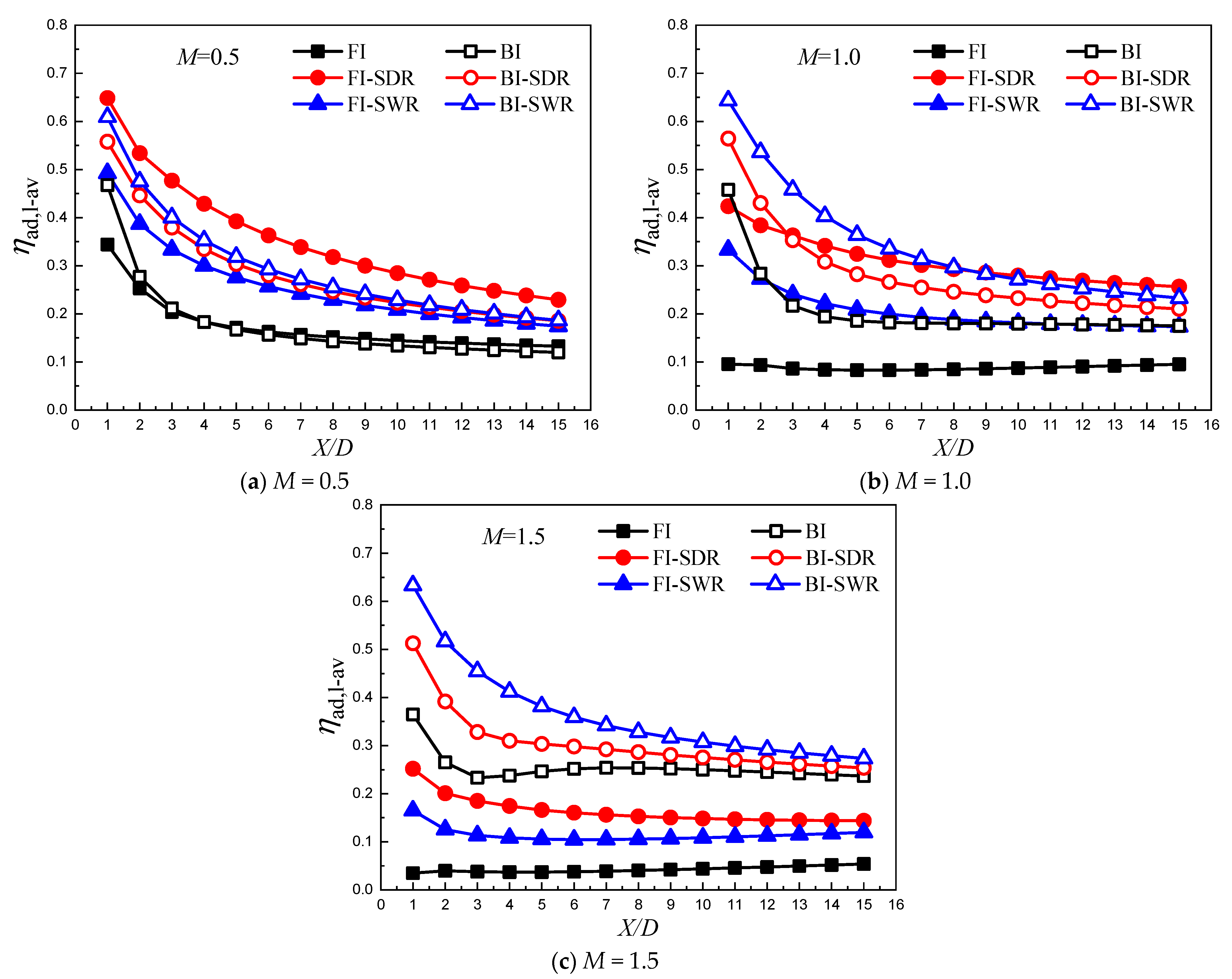
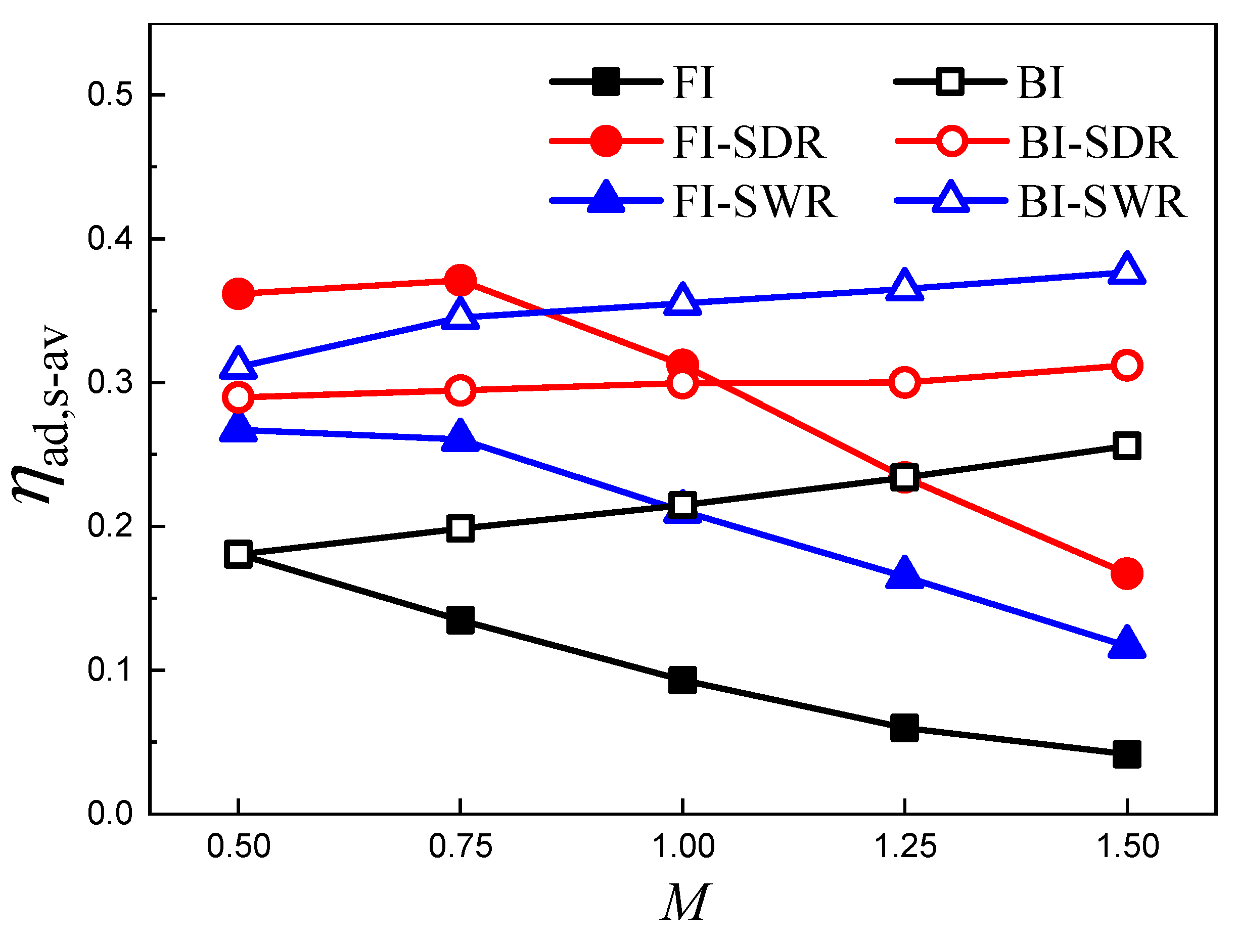
Figure 15 presents the variations of the ηad,l-av along the streamwise direction. Figure 16 presents the spatially averaged adiabatic film cooling effectiveness (ηad,s-av) in the region of 0 ≤ X/D ≤ 15. In the absence of upstream ramps, it is confirmed that backward injection film cooling leads to a significant cooling enhancement over the forward injection scheme under M = 1.0 and M = 1.5. Under a low blowing ratio of M = 0.5, the backward injection produces greater ηad,l-av in the immediate downstream region behind the film cooling hole (X/D < 2) but slightly lower ηad,l-av on the far downward film-cooled surface (X/D ≥ 3) than the forward injection. These findings agree well with the previous findings of Zhao et al. [37], who suggested that the critical blowing ratio in cylindrical hole film cooling, where backward injection performance surpasses that of the forward injection, is 0.5.
For film cooling in the presence of SDR, as seen in Figure 15a, it is found that backward injection leads to an obvious reduction of ηad,l-av on the entire streamwise space compared to forward injection for M = 0.5. For M = 1.0, as seen in Figure 15b, backward injection improves near-field film cooling (X/D ≤ 2) but reduces far-field film cooling. When operating at M = 1.5, as shown in Figure 15c, the backward injection increases ηad,l-av significantly on the entire streamwise space. As seen from Figure 16, under M = 1.0, both coolant injection schemes produce nearly the same spatially averaged adiabatic film cooling effectiveness, suggesting that the critical blowing ratio in the SDR film cooling is approximately M = 1.0. Thus, the use of SDR results in an increase in the critical blowing ratio. However, for film cooling in the presence of a SWR, backward injection improves over forward injection in film cooling effectiveness, regardless of blowing ratios.
While the SDR outperformed the SWR in the forward injection film cooling situations [26], in the backward injection scheme, the SWR has a greater effect on film cooling enhancement than does SDR. For spatially averaged adiabatic film cooling effectiveness, as seen in Figure 16, ηad,s-av for the forward injection generally decreases with increasing blowing ratio (within the current range), both with and without the use of upstream ramps. The opposite is true for backward injection film cooling. In particular, backward injection greatly improves film cooling effectiveness when using a high blowing ratio of M = 1.5. A simple backward injection in the baseline cylindrical-hole configuration (without the use of upstream ramps) can result in a greater ηad, s-av than a forward injection with an upstream ramp.

4. Conclusions

A comparative investigation is performed to investigate two upstream ramp structures, referred to as SWR (straight-wedge-shaped ramp) and SDR (sand-dune-shaped ramp) in the backward-injection film cooling over a flat surface, under a series of blowing ratios ranging from M = 0.5 to M = 1.5. From the present study, the main conclusions are drawn as follows:
(1) In the backward injection film cooling, the near-field flow in the vicinity of the film cooling hole is chaotic, coupled with a flow separation behind the coolant jet and a pair of separate wake vortices near the trailing edge of the film hole on the horizontal plane. Regarding the backward injection, the key mechanism of upstream ramps on film cooling enhancement is suggested to be the enlargement of the horizontal scale of the separate wake vortices and the reduction of their normal dimension.
(2) For the SDR, a critical blowing ratio for identifying the most possibilities of film cooling enhancement with the use of backward injection when compared to the forward injection is about M = 1.0, which is bigger than that in the baseline film cooling situation in the absence of upstream ramps. For the SWR, the backward injection shows a strongly positive action on film cooling enhancement, regardless of blowing ratios.
(3) For the backward injection, the spatially averaged adiabatic film cooling effectiveness in a specified zone of 0 ≤ X/D ≤ 15 is increased with the increase in blowing ratio generally. The SWR demonstrates a more pronounced enhancement in the film cooling than the SDR. These findings are opposite to those in the forward injection. Under high blowing ratios, the backward injection is a useful scheme to greatly improve film cooling effectiveness.
(4) With the use of upstream ramps, the impact of oncoming primary flow on the coolant injection is effectively alleviated such that the normal penetration of the coolant jet is a little suppressed and the lateral spreading of the coolant jet is enhanced. When compared to the SDR, the SWR modifies the backward coolant injection well, such that a larger volume of coolant is suctioned and concentrated in the near-field region at the film-hole trailing edge.

Author Contributions

Computation and writing—original draft preparation, S.Z.; writing—review and editing, funding acquisition, J.Z. and X.T.; methodology and formal analysis, C.W.; formal analysis, funding acquisition, J.G. All authors have read and agreed to the published version of the manuscript.

Funding

This research was funded by the National Science and Technology Major Project of China, grant number J2019-III-0019-0063; the Interdisciplinary Innovation Foundation for Graduates, NUAA, China, grant number KXKCXJJ202002; and the Nanjing University of Aeronautics and Astronautics PhD short-term visiting scholar project, grant number ZDGB2021025.

Institutional Review Board Statement

Not applicable.

Informed Consent Statement

Not applicable.

Data Availability Statement

Not applicable.

Conflicts of Interest

The authors declare no conflict of interest.

Nomenclature

Cpdimensionless pressure coefficient
Dfilm hole diameter (mm)
DRdensity ratio
Hfilm hole height (mm)
Hrramp height (mm)
L1distance between central slope edge of SDR and film-hole center (mm)
L2distance between rear step of SWR and film-hole center (mm)
Lffront-body length of SDR (mm)
Lmmiddle-body length of SDR (mm)
Lrramp length (mm)
Mblowing ratio
Phole-to-hole pitch (mm)
ppressure (Pa)
ReReynolds number
Ttemperature (K)
Tuturbulence intensity level
uvelocity (m/s)
Whorn-spacing of SDR (mm)
Xx-direction, streamwise distance (mm)
Yy-direction, normal distance (mm)
Zz-direction, spanwise distance (mm)
Greek Letters
αinclination angle of film hole (°)
ηadadiabatic film cooling effectiveness
ρdensity (kg/m3)
Θdimensionless temperature
Subscripts
awrelative to adiabatic wall
crelative to coolant
l-avlaterally averaged
s-avspatially averaged
wrelative to wall
relative to primary flow

References

  1. Acharya, S.; Kanani, Y. Advances in film cooling heat transfer. Adv. Heat Transfer 2017, 49, 91–156. [Google Scholar]
  2. Zhang, J.Z.; Zhang, S.C.; Wang, C.H.; Tan, X.M. Recent Advances in Film Cooling Enhancement: A Review. Chin. J. Aeronaut. 2020, 33, 1119–1136. [Google Scholar] [CrossRef]
  3. Aga, V.; Rose, M.; Abhari, R.S. Experimental Flow Structure Investigation of Compound Angled Film Cooling. ASME J. Turbomach. 2008, 130, 031005. [Google Scholar] [CrossRef]
  4. Kannan, E.; Sivamani, S.; Roychowdhury, D.G.; Prekumar, T.M.; Hariam, V. Improvement in Film Cooling Effectiveness Using Single and Double Rows of Holes with Adverse Compound Angle Orientations. ASME J. Therm. Sci. Eng. Appl. 2019, 11, 021014. [Google Scholar] [CrossRef]
  5. Baek, S.I.; Ahn, J. Large Eddy Simulation of Film Cooling Involving Compound Angle Hole with Bulk Flow Pulsation. Energies 2021, 14, 7659. [Google Scholar] [CrossRef]
  6. Bunker, R.S. A Review of Turbine Shaped Film Cooling Technology. ASME J. Heat Transf. 2005, 127, 441–453. [Google Scholar] [CrossRef]
  7. Kim, S.M.; Lee, K.D.; Kim, K.Y. A comparative analysis of various shaped film-cooling holes. Heat Mass Transf. 2012, 48, 1929–1939. [Google Scholar] [CrossRef]
  8. Lee, S.I.; Jung, J.Y.; Song, Y.J.; Kwak, J.S. Effect of Mainstream Velocity on the Optimization of a Fan-Shaped Film-Cooling Hole on a Flat Plate. Energies 2021, 14, 3573. [Google Scholar] [CrossRef]
  9. Baek, S.I.; Ryu, J.; Ahn, J. Large Eddy Simulation of Film Cooling with Forward Expansion Hole: Comparative Study with LES and RANS Simulations. Energies 2021, 14, 2063. [Google Scholar] [CrossRef]
  10. Bunker, R.S. Film Cooling: Breaking the Limits of Diffusion Shaped Holes. Heat Transf. Res. 2010, 41, 627–650. [Google Scholar] [CrossRef]
  11. Lee, K.D.; Kim, W.Y. Film Cooling Performance of Cylindrical Holes Embedded in a Transverse Trench. Num. Heat Transf. A 2014, 65, 127–143. [Google Scholar] [CrossRef]
  12. Song, Y.J.; Park, S.H.; Kang, Y.J.; Kwak, J.S. Effects of Configuration on Film Cooling Effectiveness of a Fan-Shaped Hole. Int. J. Heat Mass Transf. 2021, 178, 121655. [Google Scholar] [CrossRef]
  13. Na, S.; Shih, T.I.-P. Increasing Adiabatic Film-cooling Effectiveness by Using an Upstream Ramp. ASME J. Heat Transf. 2007, 129, 464–471. [Google Scholar] [CrossRef]
  14. Barigozzi, G.; Franchini, G.; Perdichizzi, A. The Effect of an Upstream Ramp on Cylindrical and Fan-Shaped Hole Film Cooling: Part I-Aerodynamic Results. In Proceedings of the ASME Turbo Expo 2007, GT2007-27077, Montreal, QC, Canada, 14–17 May 2007. [Google Scholar]
  15. Barigozzi, G.; Franchini, G.; Perdichizzi, A. The Effect of an Upstream Ramp on Cylindrical and Fan-Shaped Hole Film Cooling: Part II-Adiabatic Effectiveness Results. In Proceedings of the ASME Turbo Expo 2007, GT2007-27079, Montreal, QC, Canada, 14–17 May 2007. [Google Scholar]
  16. Chen, S.P.; Chyu, M.K.; Shih, T.I.-P. Effects of Upstream Ramp on the Performance of Film Cooling. Int. J. Therm. Sci. 2011, 50, 1085–1094. [Google Scholar] [CrossRef]
  17. Rallabandi, A.P.; Grizzle, J.; Han, J.C. Effect of Upstream Step on Flat Plate Film Cooling Effectiveness Using PSP. ASME J. Turbomach. 2011, 133, 041024. [Google Scholar] [CrossRef]
  18. Abdala, A.M.; Elwekeel, F.N. An Influence of Novel Upstream Steps on Film Cooling Performance. Int. J. Heat Mass Transf. 2016, 93, 86–96. [Google Scholar] [CrossRef]
  19. Abdala, A.M.; Elwekeel, F.N.; Huang, D. Film Cooling Effectiveness and Flow Structures for Novel Upstream Steps. Appl. Therm. Eng. 2016, 105, 397–410. [Google Scholar] [CrossRef]
  20. Hammami, Z.; Dellil, Z.A.; Nemdili, F.; Azzi, A. Improving Adiabatic Film-Cooling Effectiveness by Using an Upstream Pyramid. Comput. Therm. Sci. 2016, 8, 135–146. [Google Scholar]
  21. Zhang, F.; Wang, X.; Li, J. The Effects of Upstream Steps with Unevenly Spanwise Distributed Height on Rectangular Hole Film Cooling Performance. Int. J. Heat Mass Transf. 2016, 102, 1209–1221. [Google Scholar] [CrossRef]
  22. Zhou, W.; Hu, H. Improvements of Film Cooling Effectiveness by Using Barchan Dune Shaped Ramps. Int. J. Heat Mass Transf. 2016, 103, 443–456. [Google Scholar] [CrossRef] [Green Version]
  23. Zhou, W.; Hu, H. A Novel Sand-Dune-Inspired Design for Improved Film Cooling Performance. Int. J. Heat Mass Transf. 2017, 110, 908–920. [Google Scholar] [CrossRef] [Green Version]
  24. Zhou, W.; Peng, D.; Wen, X.; Liu, Y.Z.; Hu, H. Unsteady Analysis of Adiabatic Film Cooling Effectiveness behind Circular, Shaped, and Sand-Dune-Inspired Film Cooling Holes: Measurement Using Fast-Response Pressure-Sensitive Paint. Int. J. Heat Mass Transf. 2018, 125, 1003–1016. [Google Scholar] [CrossRef]
  25. Zhang, S.C.; Zhang, J.Z.; Tan, X.M. Numerical Investigation of Film Cooling Enhancement Using an Upstream Sand-Dune-Shaped Ramp. Computation 2018, 6, 49. [Google Scholar] [CrossRef] [Green Version]
  26. Zhang, S.C.; Zhang, J.Z.; Tan, X.M. Film Cooling Enhancement by Using Upstream Sand-Dune-Shaped Ramp. J. Aerosp. Power 2020, 35, 973–982. [Google Scholar]
  27. Zhang, S.C.; Zhang, J.Z.; Wang, C.H.; Tan, X.M. Improvement on Shaped-Hole Film Cooling Effectiveness by Integrating Upstream Sand-Dune-Shaped Ramps. J. Aeronaut. 2021, 34, 42–55. [Google Scholar] [CrossRef]
  28. Li, X.C.; Subbuswamy, G.; Zhou, J. Performance of Gas Turbine Film Cooling with Backward Injection. Energy Power Eng. 2013, 5, 132–137. [Google Scholar] [CrossRef]
  29. Subbuswamy, G.; Li, X.C.; Gharat, K. Numerical Simulation of Backward Film Cooling with Fan-Shaped Holes. In Proceedings of the ASME 2013 Heat Transfer Summer Conference, HT2013-17801, Minneapolis, MN, USA, 14–19 July 2013. [Google Scholar]
  30. Subbuswamy, G.; Li, X.C.; Gharat, K. Numerical Study of Aerodynamic Performance of Film Cooling with Backward Injection Holes. In Proceedings of the ASME 2013 Heat Transfer Summer Conference, HT2013-17803, Minneapolis, MN, USA, 14–19 July 2013. [Google Scholar]
  31. Park, S.; Jung, E.Y.; Kim, S.H.; Sohn, H.S.; Cho, H.H. Enhancement of Film Cooling Effectiveness Using Backward Injection Holes. Int. J. Therm. Sci. 2016, 110, 314–324. [Google Scholar] [CrossRef]
  32. Singh, K.; Premachandran, B.; Ravi, M.R. Experimental and Numerical Studies on Film Cooling with Reverse/Backward Coolant Injection. Int. J. Therm. Sci. 2017, 111, 390–408. [Google Scholar] [CrossRef]
  33. Prenter, R.; Hossain, M.A.; Agricola, L.; Ameri, A.; Bons, J.P. Experimental Characterization of Reverse-Oriented Film Cooling. In Proceedings of the ASME Turbo Expo 2017, GT2017-64731, Charlotte, NC, USA, 26–30 June 2017. [Google Scholar]
  34. Wang, J.; Liu, C.; Zhao, Z.M.; Baleta, J.; Sunden, B. Effect and Optimization of Backward Hole Parameters on Film Cooling Performance by Taguchi Method. Energy Convers. Manag. 2020, 214, 112809. [Google Scholar] [CrossRef]
  35. Chen, A.F.; Li, S.J.; Han, J.C. Film Cooling with Forward and Backward Injection for Cylindrical and Fan-Shaped Holes Using PSP Measurement Technique. In Proceedings of the ASME Turbo Expo 2014, GT2014-26232, Dusseldorf, Germany, 16–20 June 2014. [Google Scholar]
  36. Li, S.J.; Chen, A.F.; Wang, W.; Han, J.C. Experimental and Computational Film Cooling with Backward Injection for Cylindrical and Fan-Shaped Holes. Proceedings of 15th International Heat Transfer Conference 2014, IHTC-15, Kyoto, Japan, 15 August 2014. [Google Scholar]
  37. Zhao, Z.C.; He, L.M.; Dai, S.J.; Shao, S. Computational Research on Film Cooling Performance of Different Shaped Holes with Backward and Forward Injection. AIP Adv. 2019, 9, 055009. [Google Scholar] [CrossRef] [Green Version]
  38. Jeong, Y.S.; Park, J.S. Effect of Inlet Compound Angle of Backward Injection Film Cooling Hole. Energies 2020, 13, 808. [Google Scholar] [CrossRef] [Green Version]
  39. Singh, A.K.; Singh, K.; Singh, D.; Sahoo, M. Large Eddy Simulations for Film Cooling Assessment of Cylindrical and Laidback Fan-Shaped Holes with Reverse Injection. ASME J. Therm. Sci. Eng. Appl. 2021, 13, 031027. [Google Scholar] [CrossRef]
  40. Zheng, D.R.; Wang, X.J.; Yuan, Q. Numerical Investigation on the Effect of Upstream Ramps on Film Cooling Performance with Backward Injection. Microsyst. Technol. 2019, 25, 3559–3570. [Google Scholar] [CrossRef]
  41. Ali Kouchih, F.B.; Boualem, K.; Grine, M.; Abbes Azzi, A. The Effect of an Upstream Dune-Shaped Shells on Forward and Backward Injection Hole Film Cooling. ASME J. Heat Transf. 2020, 142, 122302. [Google Scholar] [CrossRef]
  42. Choi, Y.K.; Hwang, H.G.; Lee, Y.M.; Lee, J.H. Effects of the Roughness Height in Turbulent Boundary Layers over Rod- and Cuboid-Roughened Walls. Int. J. Heat Fluid Flow 2020, 85, 108644. [Google Scholar] [CrossRef]
  43. Mori, E.; Quadrio, M.; Fukagata, K. Turbulent Drag Reduction by Uniform Blowing over a Two-Dimensional Roughness. Flow turbul. Combust. 2017, 99, 765–785. [Google Scholar] [CrossRef]
  44. Hamed, A.M.; Nye, C.E.; Hall, A.J. Effects of Localized Blowing on the Turbulent Boundary Layer over 2D Roughness. Exp. Fluids 2021, 62, 1–13. [Google Scholar] [CrossRef]
  45. Djenidi, L. Kamruzzaman, M.; Dostal, L. Effects of Wall Suction on a 2D Rough Wall Turbulent Boundary Layer. Exp. Fluids 2019, 60, 43. [Google Scholar] [CrossRef]
  46. Ghanadi, F.; Djenidi, L. Reynolds Number Effect on the Response of a Rough Wall Turbulent Boundary Layer to Local Wall Suction. J. Fluid. Mech. 2021, 916, A25. [Google Scholar] [CrossRef]
  47. ANSYS Fluent 14.0 User’s Guide; ANSYS Inc.: Canonsburg, PA, USA, 2012.
  48. Ely, M.J.; Jubran, B.A. A Numerical Evaluation on the Effect of Sister Holes on Film Cooling Effectiveness and the Surrounding Flow Filed. Heat Mass Transf. 2009, 45, 1435–1446. [Google Scholar] [CrossRef]
  49. Foroutan, H.; Yavuzkurt, S. Numerical Simulations of the Near-Field Region of Film Cooling Jets under High Free Stream Turbulence: Application of RANS and Hybrid URANS/Large Eddy Simulation Models. ASME J. Heat Transf. 2015, 137, 011701. [Google Scholar] [CrossRef]
  50. Zhu, R.; Simon, T.W.; Xie, G.N. Influence of secondary hole injection angle on enhancement of film cooling effectiveness with horn-shaped or cylindrical primary holes. Num. Heat Transf. Part A 2018, 74, 1207–1227. [Google Scholar] [CrossRef]
  51. Hang, J.; Zhang, J.; Wang, C.; Shan, Y. Numerical Investigation of Single-Row Double-Jet Film Cooling of a Turbine Guide Vane under High-Temperature and High-Pressure Conditions. Energies 2022, 15, 287. [Google Scholar] [CrossRef]
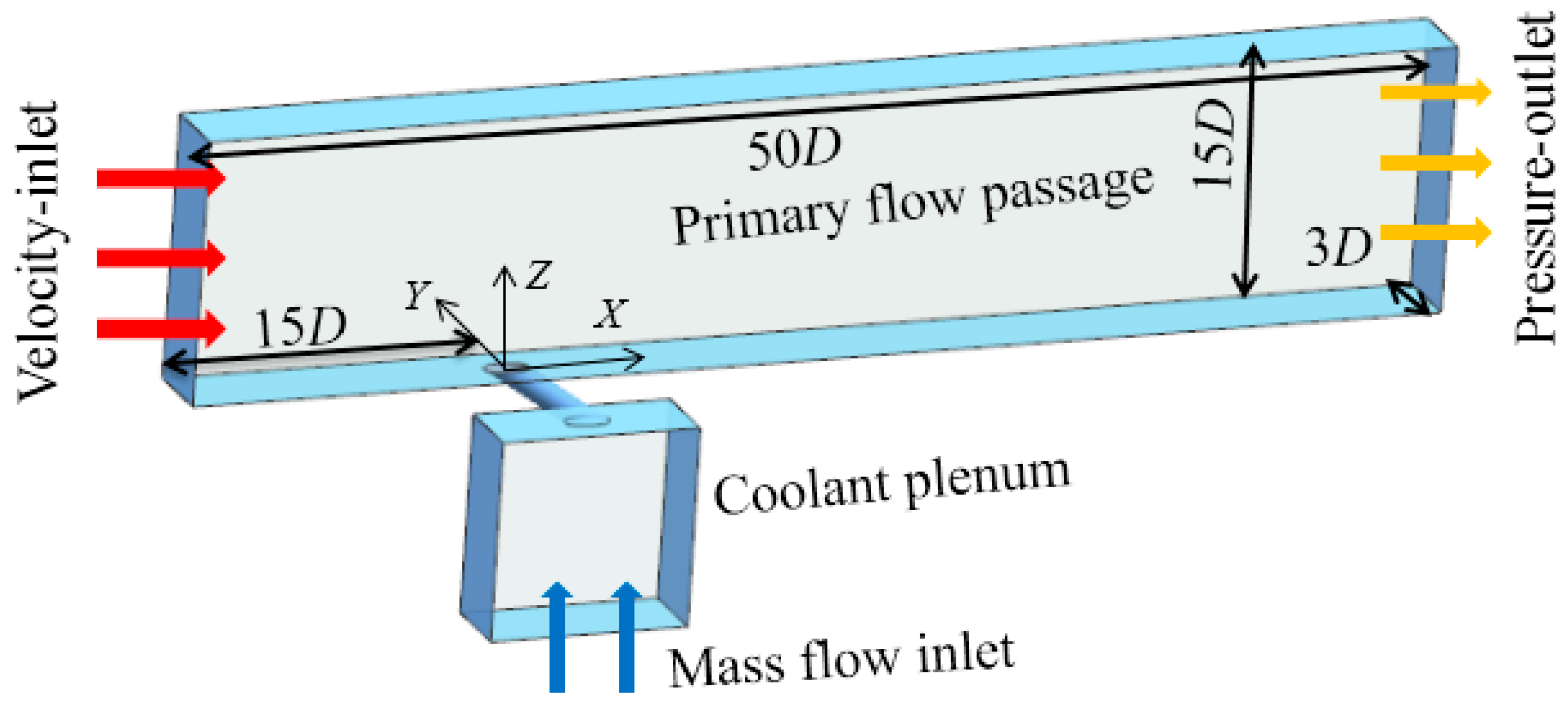
Figure 1. Schematic of computational domain.
Energies 15 04415 g001
Figure 2. Schematic diagram of upstream ramps: (a) detailed parameters of SDR; (b) detailed parameters of SWR.
Energies 15 04415 g002
Figure 3. Validation of computational scheme for the SDR case (Experiment, Zhou et al. [22]).
Energies 15 04415 g003
Figure 4. Schematic of representative computational meshes.
Energies 15 04415 g004aEnergies 15 04415 g004b
Figure 5. The grid-independent test for the SWR case under M = 0.5.
Energies 15 04415 g005
Figure 6. Local streamlines colored by the dimensionless temperature in BI cases.
Energies 15 04415 g006
Figure 7. Static gauge pressure contours on a horizontal plane of Z/D = 0.125 in BI cases.
Energies 15 04415 g007
Figure 8. Dimensionless temperature contours and streamlines on film-hole centerline plane in BI cases.
Energies 15 04415 g008
Figure 9. Dimensionless normal injection velocity contours at the film-hole exit in BI cases.
Energies 15 04415 g009
Figure 10. Dimensionless temperature contours and streamlines on horizontal plane of Z/D = 0.125 in BI cases.
Energies 15 04415 g010
Figure 11. Local streamlines and dimensionless temperature contours at X/D = 2, 4, 6 in BI cases.
Energies 15 04415 g011
Figure 12. Adiabatic film cooling effectiveness distributions in BI cases under M = 0.5.
Energies 15 04415 g012
Figure 13. Adiabatic film cooling effectiveness distributions in BI cases under M = 1.0.
Energies 15 04415 g013
Figure 14. Adiabatic film cooling effectiveness distributions in BI cases under M = 1.5.
Energies 15 04415 g014
Figure 15. Laterally averaged adiabatic film cooling effectiveness distributions.
Energies 15 04415 g015
Figure 16. Spatially averaged adiabatic film cooling effectiveness.
Energies 15 04415 g016
Table 1. Main geometric parameters.
ParametersSymbolValue
ramp heightHr2.0 mm (0.5 D)
length of SDRLr14.4 mm (3.6 D)
front-wedge length of SDRLf5.4 mm (1.35 D)
middle-slope length of SDRLm1.8 mm (0.45 D)
horn-spacing of SDRW11.4 mm (2.85 D)
hole-to-ramp distanceL14.0 mm (1.0 D)
Length of SWRL27.2 mm (1.8 D)
Table 2. Boundary conditions.
ItemsBoundary Conditions
Primary flow at the inletVelocity, u = 25 m/s
Temperature, T = 360 K
Turbulence intensity, Tu = 2%
Cooling air at plenum inletBlowing ratio,M = 0.5~1.5
Temperature, Tc = 300 K
Density ratio,DR = 1.2
Mixing flow at the outletStatic pressure,pout = 101,325 Pa
Channel-top planeSymmetry
Channel-side planesPeriodic boundary condition
Film-cooled surfaceNo-slip and adiabatic-thermal condition
Publisher’s Note: MDPI stays neutral with regard to jurisdictional claims in published maps and institutional affiliations.