Article

A Novel Forked-Finger Electrode-Structured Thermoelectric Module with High Output Power

State Key Laboratory of Information Photonics and Optical Communications, Beijing University of Posts and Telecommunications, Beijing 100876, China
*
Author to whom correspondence should be addressed.
Energies 2022, 15(12), 4430; https://doi.org/10.3390/en15124430
Submission received: 2 April 2022 / Revised: 7 June 2022 / Accepted: 15 June 2022 / Published: 17 June 2022

Abstract

:
Thermoelectric harvesting technology is a clean and friendly energy-conversion technology. In the π-type traditional thermoelectric module (TEM), n- and p-type thermoelectric legs are electrically connected in a series to generate large temperature differences in the heat flow direction and to achieve a better module performance. However, damages to one thermoelectric leg could lead to the failure of the thermoelectric system. This work proposes a novel forked-finger electrode-structured thermoelectric module (FFTEM), which enables a simultaneous parallel electrical connection and thermal transfer in a homogeneous material’s thermoelectric leg set. The four thermoelectric legs share a common pair of electrodes, and this parallel structure makes the FFTEM benefit from low internal resistance, a high operating current, and high output power. The internal resistance and output power of the TEM are 4.25 mΩ and 1.766 mW, respectively, at a temperature difference of 40 °C. The internal resistance of the FFTEM is reduced to 0.81 mΩ, and the output power is increased to 13.81 mW. The FFTEM’s maximum output power achieved under temperature-dependent conditions is nine times that of the TEM’s output power. This FFTEM design provides a configuration to obtain a much higher output power, which could benefit future applications of thermoelectric devices.

1. Introduction

In industry, two-thirds of energy is wasted in the form of heat, resulting in low energy efficiency [1,2]. To achieve sustainable economic development under energy constraints, it is necessary to develop efficient and clean energy-conversion technologies [3]. As a promising thermal management technology, thermoelectrics directly convert heat into electrical energy [4]. Thermoelectric generation (TEG) converts heat energy into electric power through the Seebeck effect and transforms electrical energy into thermal energy to enable cooling or heating through the Peltier effect. The constituent materials of the TEG play a significant role in the operation of TEGS and are determined using a dimensionless figure of merit, defined as Z T = α 2 / ρ k T , where α is the Seebeck coefficient, ρ is the electric resistivity, k is the thermal conductivity, and T is the absolute temperature [5]. Since the historic discoveries of the thermoelectric phenomenon in the first half of the 19th century, several materials have been explored and considered useful for generating thermoelectricity. In the past 20 years, the science of thermoelectric materials has developed in an unprecedented manner. The iconic index of thermoelectric material performance, Z T , is constantly being refreshed. The maximum Z T value of various materials has exceeded 1.5 or even 2.0 [6]. The achievements of thermoelectric materials have greatly advanced the use of thermoelectric technology in practice [7].
Current cogeneration technology is being researched more and more extensively in the field of green energy, and the use of low-grade heat sources is also receiving widespread attention [8]. Thermoelectric power generation technology has been developed. TEG is a kind of thermoelectric device that directly converts heat energy into electricity, and it is made of semiconductor thermoelectric materials with excellent performance. As a way of obtaining electrical energy from nature, it operates without media, wear parts, noise, and vibration and is therefore green and pollution-free, with a stable and reliable life [7,9]. Many efforts have been made by researchers to produce more electricity by optimising the TEG [10,11].
The structure of the thermoelectric device determines the transmission of heat and currents and is an important parameter in determining the output characteristics of the thermoelectric device. Traditional π -type thermoelectric modules (TEM) are thermal parallel and electrical series. The transmission method is used to increase the output power of the device by obtaining a high output voltage [12,13]. However, the real applications of TEGs are limited due to their relatively low output power [14,15]. Researchers have, therefore, tried to work on everything from looking for better thermoelectric materials to changing geometrical parameters and other optimisations [16,17,18]. For example, Lamba et al. [19] investigated the effect of thermoelectric leg configuration on the performance of thermoelectric power generation systems and found that the external energy and the energy efficiency of a trapezoidal TEG increased by 2.31 and 2.32%, respectively, under certain conditions. Hodes et al. [20] proposed a method for optimising the number of thermoelectric legs to obtain maximum output power or conversion efficiency. Karana et al. [21] conducted numerical and experimental studies of thermoelectric generators with asymmetric thermoelectric legs and proved the impact of the performance of the TEG on the improvement [22]. In the case of series thermoelectric structures, damage to a single thermoelectric leg can lead to the failure of the entire device, and the internal resistance of the thermoelectric component is severe [23]. New designs are urgently needed to further increase the power output to meet the requirements of electrical equipment [24].
In addition, the internal resistance of the thermoelectric device is a serious obstacle to the power increase. To solve these problems, different electrical parallel structures have been proposed by domestic and foreign scholars. Hongchao Wang et al. proposed a thermoelectric module with a multilayer chip with a temperature difference of 35 °C. The internal resistance and current of this module are 0.03 and 12.7 times higher than those of conventional thermoelectric modules under the same conditions, respectively, and its maximum output power can reach 5.8 mW [25]. The multilayer composite-structured thermoelectric module offers new ideas for the structural design of thermoelectric devices. However, their work does not analyse the output characteristics of the device under transient conditions, nor does it discuss the effect of thermal contact resistance on device performance.
With the rapid development of semiconductor lasers and fiber optic technologies, power-by-light (PBL) has been used in various fields, such as optically powered remote antenna units and remote sensors in hazardous environments [26,27]. The most used in PBL systems are GaAs- and AlGaAs-based broad-area laser diodes emitting at 808 nm with efficiencies around 40% [28]. Laser diodes emitting at around 900 nm and beyond (940–980 nm) reach efficiencies over 70% [29]. More than half of the light power in the photovoltaic conversion process is dissipated in the environment in the form of waste heat. The PBL system has the characteristics of high-power density, small heat source area, fast temperature change, and controllable energy pulse. It makes it possible to establish periodic temperature boundary conditions.
This study proposes an FFTEM and investigates the electrode dimensions, the geometrical parameters of the thermoelectric leg, and the contact heat. The effects of the electrode size, thermoelectric leg geometry, and thermal contact resistance on the module’s performance are investigated. The module has a very low internal resistance and the FFTME has a higher output power at steady-state conditions. In addition, the output characteristics of the FFTEM and TEM were investigated under time-dependent periodic temperature conditions. The output power of the FFTEM is 8.77 mW, which is nine times higher than the output power of the TEM. This new structure increases the commercial potential of TEGs and offers new ideas for the application of TEGs in low-quality heat sources.

2. Simulation Approach

2.1. Theoretical Equations

The Fourier equation for the flow through the thermoelectric generation device is
ρ d C p ( T x + u · T ) + · ( q + q r ) = Q h + I 2 R i n 2 α T : d S d t .
the left side of the equation represents time, heat convection, heat conduction, and heat radiation, while the right side shows the heat source, Joule heat, and thermoelastic damping. The ρd, C p , u, q, q r , Q h , R i n , I, and T are the material density, the constant pressure heat capacity of the material, translational velocity vector, conduction heat flow density, radiation heat flow density, total heat absorption, the internal resistance of the thermoelectric device, circuit current, and the absolute temperature of the thermoelectric device. If the electrical and thermal resistance between the interfaces, lateral heat loss, and Thomson’s heat are ignored, the net heat flow into this closed system will eventually move in one direction along the high-temperature end towards the low-temperature end.
The mechanism of TEG can be determined by both the electric field and heat transfer. When the temperature gradient T is specified, the electrical field E generated in the thermoelectric material is expressed as Equation (1) [30]:
E = α T ρ J ,
Here, α , ρ , and J denote the Seebeck coefficient, resistivity, and current density, respectively. The Peltier effect, which explains the heat flux q in the thermoelements, is expressed as follows:
q = α T J + k T .
Thermal contact resistance and electrical contact resistance are the main factors affecting the performance of the thermoelectric components. The thermal contact resistance affects the heat flow transfer between the contact interfaces, while the heat in the boundary layer depends on the difference in the interface temperature.
n u · ( k u T u ) = h ( T d T u ) + ( 1 r ) Q b ,
n d · ( k d T d ) = h ( T u T d ) + r Q b ,
where n is the unit vector, Q b is the frictional heat between the electrode and the thermoelectric leg, r is Charron’s relational definition, and the subscripts u and d point to the upper and lower boundaries, respectively. h is the total thermal conductance of the interface, which is mainly determined by the shrinkage and contraction of the thermal conductivity ( h c ) and the gap thermal conductivity ( h g ). The h c is related to the types of the two contact materials between the interface, while h g is related to the thermal conductance of the gas inside the interface void.
h c = 1.25 k c o n t a c t m m + h ( p H c ) ,
k c o n t a c t = 2 k u k d ( k u + k d ) ,
h g = k g a p Y + M g , M g = α β Λ , Λ = k B T B 2 π D 2 p g ,
As shown in the above equation, h is very relevant for the average surface roughness slope ( m = tan θ , θ is the surface tilt angle) and the positive surface pressure (P) is also very relevant. Here, k c o n t a c t is the surface’s thermal contact conductivity; m h is the average roughness; H c is the material hardness; Y is the interfacial contact material; α and β are gas property parameters; λ is the mean free range of the gas; k B is the Boltzmann constant; D is the mean gas particle diameter; and p g is the gas pressure.
The contact resistance impedes the interfacial current transfer. The current density ( J u , J d ) at the upper and lower interfaces depends on the interface’s potential difference, which is related as follows:
n · J u = h e c ( V u V d ) ,
n · J d = h e c ( V d V u ) ,
where n is the unit vector of current and h e c is the interfacial electrical conduction, defined by the Cooper–Mikic–Yovanovich relation.
h e c = 1.25 σ c o n t a c t m m h p H c .

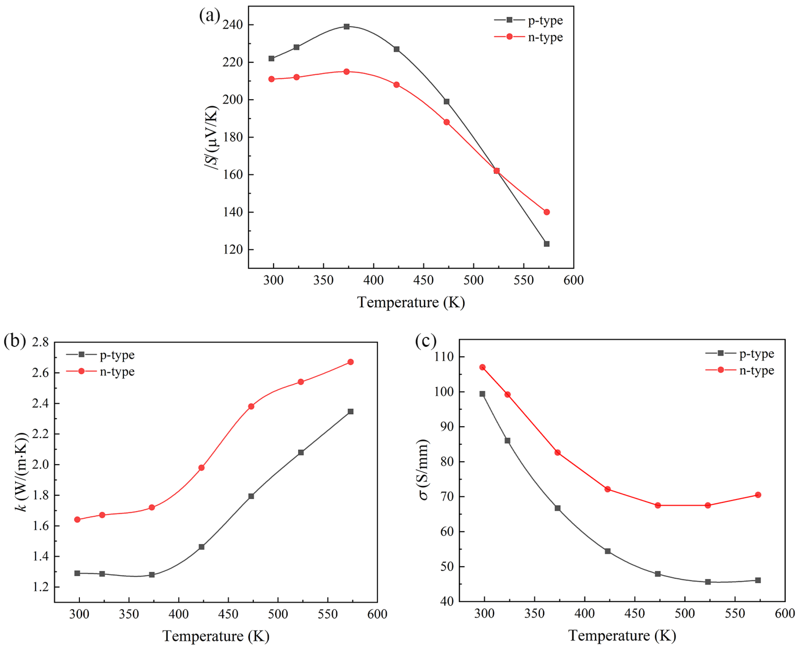
2.2. Material Parameters

The materials that make up the FFTEM module include a substrate composed of ceramic plates, electrodes composed of copper metal, and n-type and p-type thermoelectric materials that enable the conversion of thermal and electrical energy. The n-type thermoelectric material is copper-doped Bi2Te2.7Se0.3. In addition, the p-type thermoelectric material is the Cu-modified Bi0.5Sb1.5Te3. The powders were sintered by spark plasma sintering under a pressure of 50 MPa at 670 K for 10 min. The main Seebeck coefficients (S), conductivity ( σ ), and thermal conductivity (k) of the materials as a function of temperature are shown in Figure 1. The absolute value of Seebeck coefficients of n-type and p-type thermoelectric materials were tested from room temperature to 573 K, with a tendency to decrease with increasing temperature. The electrical and thermal conductivities of the materials showed a non-linear change with increasing temperature. The FFTEM module designed for this work is mainly referenced in environments with low temperature differences, so that the effect of temperature variation on material parameters can be neglected.

2.3. Boundary Conditions

This work presents a comprehensive 3D numerical study of the effects of different parameters on the performance of the FFTEM model using COMSOL 5.5 Multiphysics software. The boundary conditions are as follows:
  • The thermophysical parameters of all material are presumed to be isotropic and independent of temperature.
  • The FFTEM model’s side boundary is considered adiabatic.
  • The initial temperature of the FFTEM model is equal to the ambient temperature.
  • The thermoelectric elements are connected in parallel both electrically and thermally.
  • It does not take into account the extremely weak Thomson effect.
  • The heat transfer is only along the height direction of the electrocouple leg; the surrounding sides are adiabatic.
  • The surface temperature of the ceramic substrate at the hot and cold ends is constant at T c , T h .
  • The magnitude of the load resistance is always the same as the magnitude of the internal resistance in order to facilitate the iterative solving process of the finite-difference method.
  • The thermal conductivity of the ceramic substrate is a constant value.
  • The cross-sectional areas of the n-type and p-type electrocouple legs are equal: A n = A p = A .

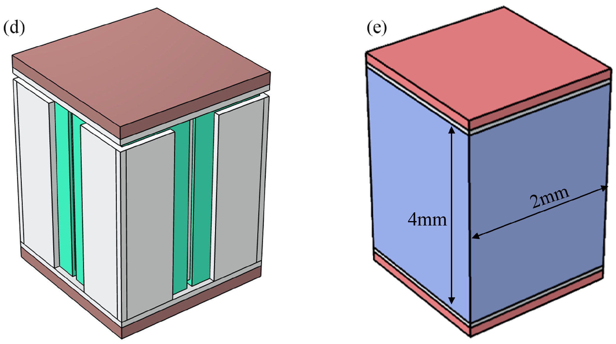
2.4. Geometric Model

Figure 2 is a schematic diagram of a panel of p-type thermoelectric legs of a thermoelectric device with a forked-finger electrode structure. Figure 2a–c are central electrode, peripheral electrode, and p-type thermoelectric material, respectively. Figure 2d is the p-type component of the FFTEM module, and Figure 2e is the p-type component of the TEM module at the same volume of thermoelectric material. The p-type group contains two alumina ceramic plates, and two electrodes and four p-type thermoelectric materials of the same material and size are used to form the thermoelectric leg group. The electrodes are semi-enclosed to the thermoelectric leg, with the positive electrode at the top and centre of the leg and the negative electrode at the bottom and outside of the leg. The central electrode is crossed, and four thermoelectric legs are distributed around the central electrode. Peripheral electrodes wrap the bottom surface and a portion of the outer sidewall of the thermoelectric leg. Two ceramic plates sandwich the thermoelectric legs and electrodes, forming a complete p-type group. The monolithic FFTEM module contains geometrically symmetric n-type and p-type components. In a FFTEM module, the group of n-type and p-type thermoelectric is implemented in series. Meanwhile, an n-type or p-type group contains four thermoelectric legs that are electrically paralleled. The cross-sectional dimensions of each of these thermoelectric legs are 1 × 1 mm.

3. Results and Discussions

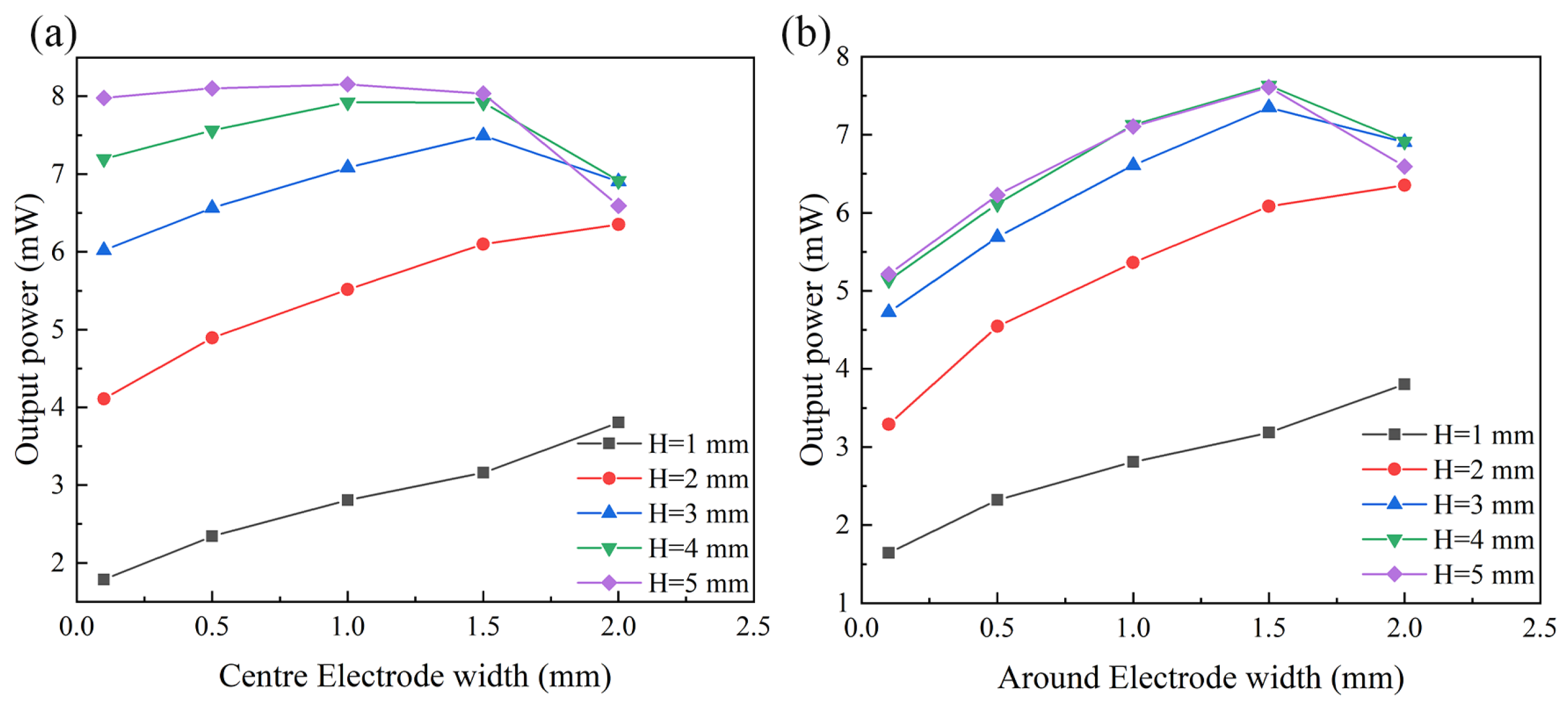
3.1. Effect of the Electrode Size

For the FFTEM modules, the forked electrode structure results in a special spatial distribution of the vector current density of the module. Electrode size has the most critical effect on the output power of the module. For a more accurate study, the thickness of the centre and around the electrodes in the FFTEM model is 0.1 mm, and the height of the electrode is kept 0.1 mm shorter than the height of the thermoelectric legs. Forked-finger electrodes are a new type of electrode structure for thermoelectric devices, so the optimisation of the electrode dimensions is particularly important. The lateral dimensions of the electrode are optimised. Different output characteristics can be obtained by changing the widths of the central and surrounding electrodes, respectively. As shown in Figure 3, when the height of the thermoelectric leg is less than 2 mm, the width of the central electrode varies from 0.1 to 2 mm, and the output power of the p-type electric leg set increases continuously. When the height of the thermoelectric leg is greater than 2 mm, the maximum output power of the p-type electric leg set occurs when the width of the centre electrode is 1.5 mm. By making the same changes to the surrounding electrodes, the same output power characteristics as the centre electrode can be obtained.

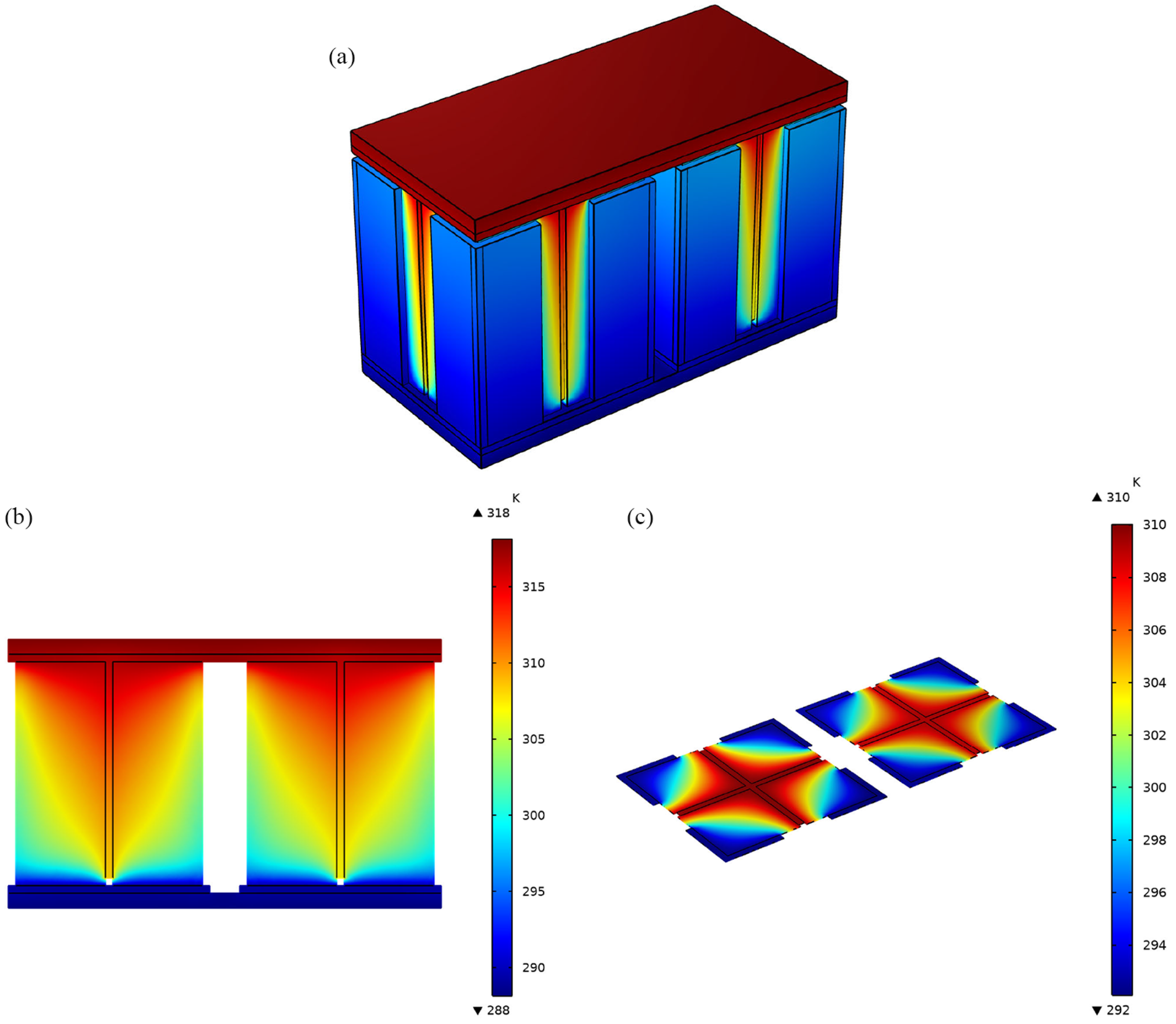
3.2. Temperature Distribution and Output Characteristics of the FFTEM

Figure 4a shows the temperature distribution of the forked-finger electrode thermoelectric module under open-circuit conditions at a temperature difference of 30 °C, where the temperature at the cold end is 15 °C and the temperature at the hot end is 45 °C. The temperature of the top ceramic substrate in the FFTEM module is higher than the temperature of the bottom ceramic substrate, and the temperature of the central electrode is higher than the temperature of the surrounding electrodes. The temperature of the top ceramic substrate in the FFTEM module is higher than the temperature of the bottom ceramic substrate, and the temperature of the central electrode is higher than the surrounding electrodes. Figure 4b shows the temperature distribution in the vertical profile of the heart of the FFTEM. In this plane, the temperature is distributed longitudinally, and the heat flow is transmitted from top to bottom. The horizontal profile in the FFTEM module is taken at half the height of the thermoelectric leg, and its temperature distribution is plotted as in Figure 4c; in the same horizontal plane, the thermal temperature distribution of the electrical module spreads from the centre outwards. This is because of the thermal conductivity of the copper; the thermal conductivity of the electrode is higher than that of the thermoelectric material, so the temperature of the central electrode is higher than that of the surrounding thermoelectric material in the same horizontal plane. When the z-axis height varies, the temperature distribution in the horizontal profile also varies. The FFTEM module uses the different thermal conductivity of the metallic copper electrodes and the thermoelectric material as a basis for the TEM module, changing the temperature distribution inside the module by regulating the electrodes. The temperature distribution within the module is changed by regulating the electrodes. This structure results in a higher output power at lower temperature differences. The temperature distribution of the TEM under open-circuit conditions with a temperature difference of 30 °C is in the Supplementary Materials Figure S1.
Figure 5 depicts the relationship between the height of the thermoelectric leg and the output power of the FFTEM module. The temperature difference has different characteristics depending on the thermoelectric leg height and output power. When the temperature difference is 10 and 20 °C, the output power of the FFTEM tends to increase and then stabilise as the height of the thermoelectric leg increases. For temperature differences of 30, 40, and 50 °C, the output power of the FFTEM increases and then decreases. The minimum accuracy of the temperature difference calculation in this paper is 0.1 °C. The FFTEM module changes the distribution of the heat flow; instead of flowing in a single direction, the heat spreads in several directions at the same time. Therefore, the height of the thermoelectric leg should not be greater than 4 mm when the cross-sectional area of the FFTEM module is constant. The relationship between the height of the thermoelectric leg and the output power of the TEM module for the same volume of thermoelectric material is shown in Figure S2 of the Supplementary Materials.

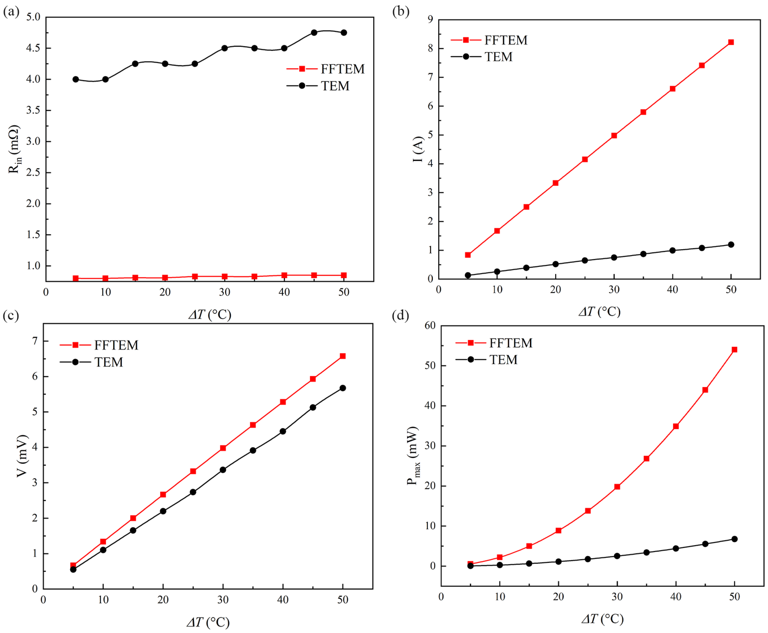
3.3. Comparison of the FFTEM Module and the TEM Module

For thermoelectric materials with equal volumes to form the FFTEM modules and TEM modules, which have different output characteristics, the height of the p-type and n-type thermopods is 4 mm in both the FFTEM module and the TEM module, the cross-section of the n-type and p-type thermoelectric legs in the TEM module are both squares with a length of 2 mm, while the cross-sections of the n-type and p-type thermopod assemblies in the FFTEM module are four square series with a length of 1 mm. Figure 6 compares the internal resistance, operating current, output voltage, and maximum output power of the FFTEM and TEM modules in the load-matched state. Figure 6a depicts the trend of the internal resistance with the temperature. From the graph, it can be seen that the internal resistance of the FFTEM module does not change significantly with differences in temperature; the resistance value is between 0.81 and 0.82 mΩ. As the temperature difference increases from 5 to 50 °C, the internal resistance of the conventional thermoelectric leg module increases from 4.0 to 4.75 mΩ. It can be seen that the FFTE has an extremely low resistance value, which is 5% of the resistance value of the TEM module. This low resistance is mainly due to the electrical parallel effect caused by the forked-finger electrode structure. Figure 6b,c depict the relationship between the operating current and output voltage and the temperature difference. When the temperature difference is 50 °C, the maximum operating current of the TEM module is 1.19 A and the maximum current of the FFTEM module is 8.2 A in a state where the load resistance is equal to the internal resistance. The increase in current causes a strong Joule heating effect and therefore the FFTEM module is more suitable for low-temperature differentials. The output voltages of the FFTEM and TEM modules are 6.57 and 5.67 mV, respectively. Figure 6d shows the maximum output power of the FFTEM module at different temperature differences. As the temperature difference increases, the maximum output power of the module increases from 0.55 to 54.01 mW. At a temperature difference of 50 degrees Celsius, the maximum output power of the FFTEM is 7.9 times that of the TEM module. As a result, the FFTEM module has a very low internal resistance, a very high current, and a much higher output power than conventional TEM modules.
Figure 7 shows a schematic diagram of the intermediate efficiency resistance of the FFTEM module and the TEM module. In the FFTEM module, the resistance of the n-type material (FFTEM Rn) and the resistance of the p-type material (FFTEM Rp) are formed by the parallel connection of four thermoelectric legs. As shown in Figure 7a, the total resistance of the FFTEM module is the sum of FFTEM Rn and FFTEM Rp. In Figure 7b, in a TEM module, the equivalent circuit is a series of n-type and p-type equivalent resistors of the material. The equivalent resistance of a FFTEM module is extremely correlated with the electrode size. The optimal output characteristics of FFTEM require consideration of the temperature difference of the device, electrode size, height, and width of the thermoelectric material.

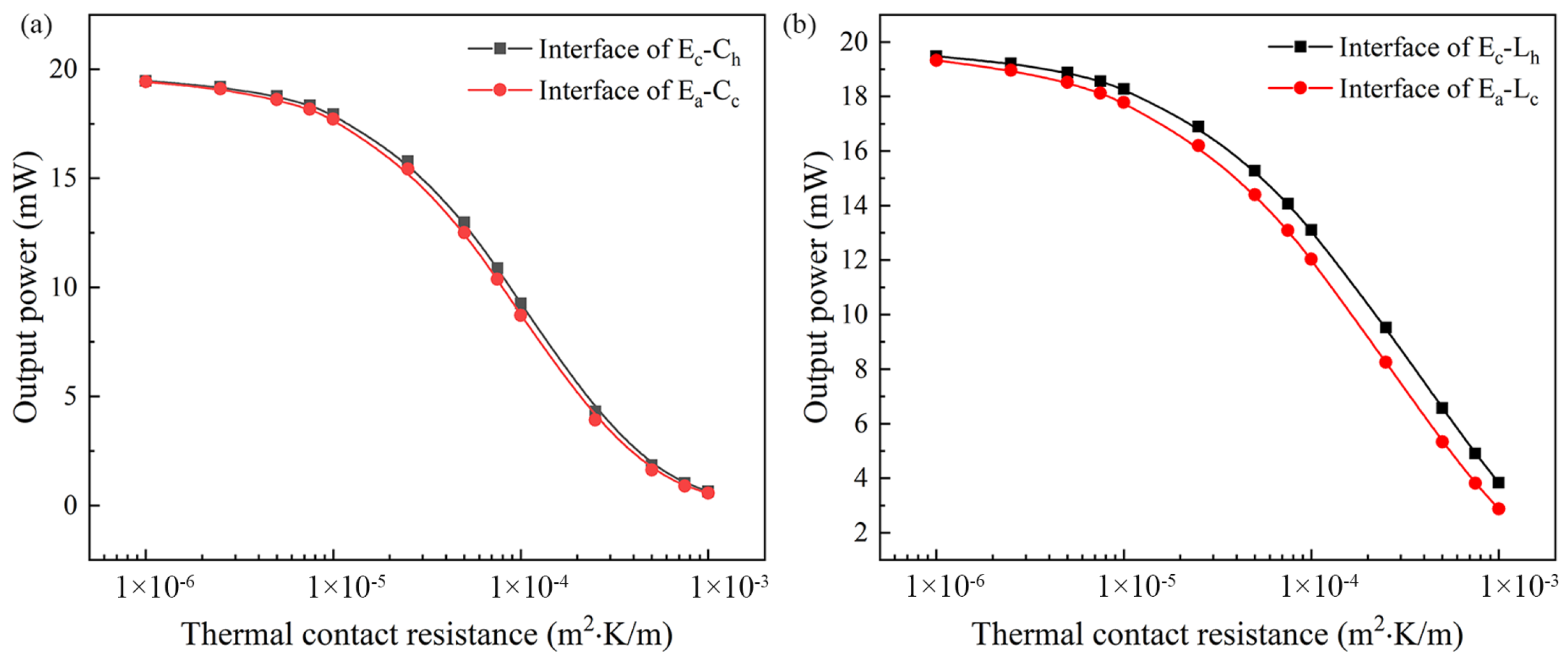
3.4. The Effect of Thermal Contact Resistance

When considering the configuration of the FFTEM module and the TEM module, the height and total cross-sectional area of the thermoelectric material are exactly equal values. However, in different modules, the connection area between the electrode and the thermoelectric material is different. In the FFETM module with the best output characteristics, the connection area of the thermoelectric material and electrode is approximately 9 times that of the TEM module with the same geometry and volume. The heat flow in a thermoelectric device passes through different contact interfaces, each of which has a certain thermal contact resistance. The existence of thermal contact resistance makes the temperature difference so that the thermoelectric device can utilise less than the temperature difference of the environment in its operation. This leads to a reduction in its power output. Therefore, different thermal contact resistances are added at different interfaces of the FFTEM to simulate the energy output of the thermoelectric device.
Figure 8 shows the relationship between the thermal contact resistance and output power. The relationship between the thermal contact resistance and the output power of the TEM module is depicted in Figure S3 of the Supplementary Materials. The base values are used for this study except the FFTEM thermal contact resistance which varied from 1 × 10⁻⁶ to 1 × 10⁻³ m2·K/W as reported in [31]. E c C h and E a C c represent the interface between the central electrode and the ceramic substrate at the hot end and the interface between the surrounding electrode and the ceramic substrate at the cold end, respectively. The effect of the thermal contact is not that significant for low values; however, once the E c C h and E a C c thermal contact resistance attains a high value such as 1 × 10⁻⁵ m2·K/W and upward, its drastic effect on the FFTEM performance becomes very clear. The thermal contact resistance between the electrode and the ends of the thermoelectric leg are E c L h and E a L c . The effect of the thermal resistance between the thermoelectric leg and the electrode on the output power of the FFTEM is less than the effect of the thermal resistance between the ceramic plate and the electrode.

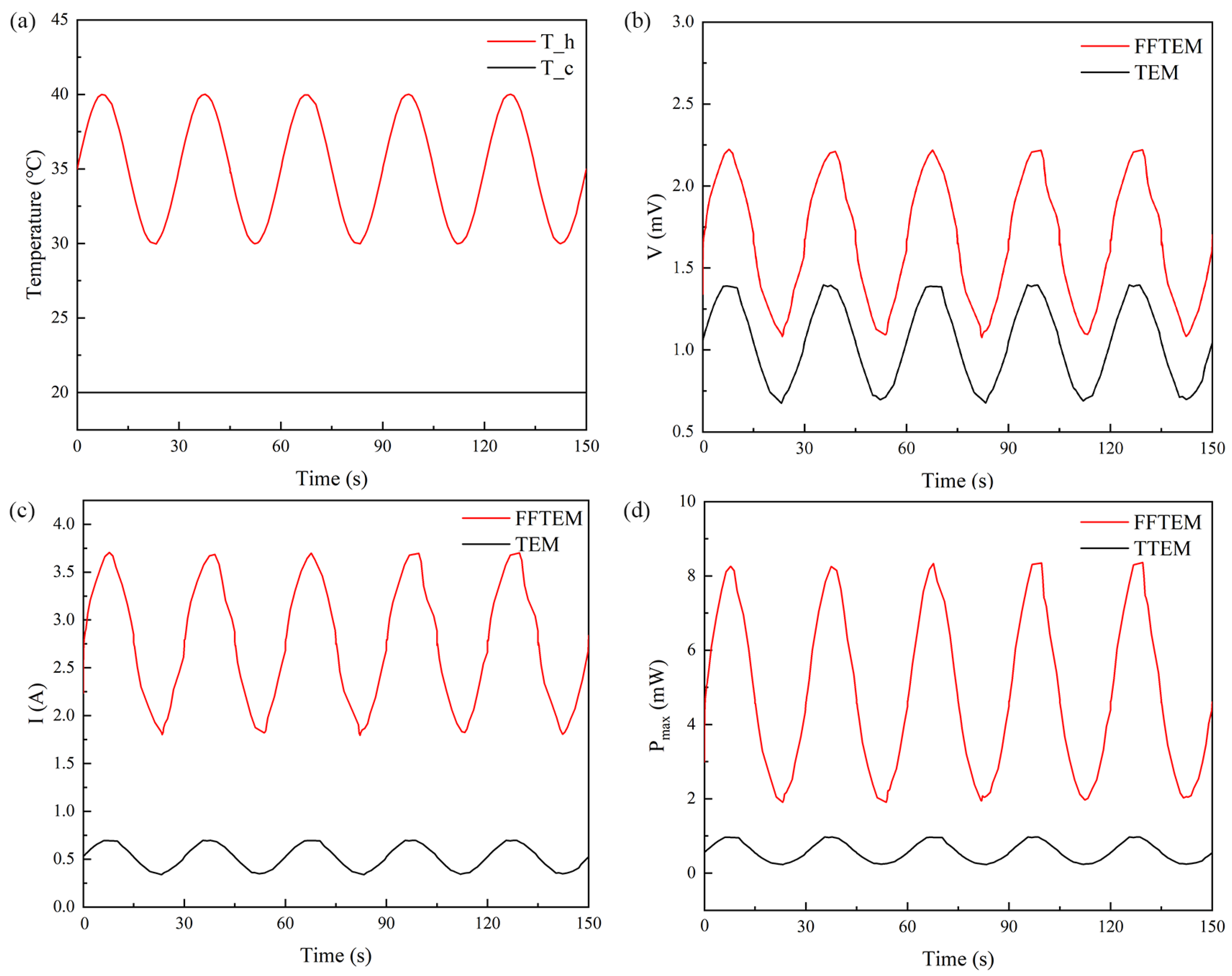
3.5. Transient Output Characteristics

To investigate the transient output characteristics of the FFTEM, the temperature conditions are shown in Figure 9a. The temperature at the cold end ( T c ) was 20 °C for both the FFTEM and TEM, and the temperature at the high end ( T h ) showed fluctuations with time. Figure 9b–d depict the output voltage, operating current, operating temperature, and the output power characteristics of the FFTEM and TEM, respectively, in the load-matching condition. When the temperature difference fluctuates sinusoidally between 10 and 20 °C with a period of 30 s, the maximum output power of the FFTEM is between 1.90 and 8.77 mW. The TEM output power ranged from 0.22 to 0.97 mW. The output power was collected over five cycles and analysed to obtain the output power of the FFTEM’s sparring, which was nine times higher than that of the TEM. The power calculations for the FFTEM and TEM modules do not include the effects of Joule diffusion. In order to increase the accuracy of the calculation, the maximum temperature difference of the FFTEM module does not exceed 20 °C under periodic temperature boundary conditions. This shows that the FFTEM has a higher output power than the TEM under fluctuating temperature conditions.
Figure 10 further investigates the relationship between the output power of the FFTEM and the output power of the TEM under conditions where the temperature difference varies with time. When the temperature difference is between 10 and 20 °C, the maximum output power of the FFTEM and TEM is 8.11 and 0.96 mW, respectively. The output power of the FFTEM still has a huge advantage. At room temperature, the FFTEM has better output characteristics than the TEM.

4. Conclusions

In the current study, a novel forked-finger electrode structure was designed to achieve greater output power. The FFTEM was optimised in terms of geometrical parameters such as electrodes and thermoelectric legs to obtain the best output state. Under certain conditions, the optimum width of the electrode for the FFTEM was 1.5 mm and the height of the thermoelectric leg should not exceed 4 mm. The FFTEM had a unique thermoelectric transmission with both thermal and electrical parallelism and had a very low internal resistance and a very high operating current, obtaining a higher output power than the TEM under the same conditions. The internal resistance and output power of the TEM were 4.25 mΩ and 1.766 mW, respectively, at a temperature difference of 40 °C. The internal resistance of the FFTEM was reduced to 0.81 mΩ, and the output power was increased to 13.81 mW. The maximum output power of the FFTEM was 7.8 times the maximum output power of the TEM. The output power of the FFTEM greatly exceeded that of the TEM in both steady-state and transient conditions. When the thermal contact resistance between the interfaces was less than 1 × 10⁻⁵ m2·K/W, the output power of the FFTEM varied less and would be expected to be produced in practice. The FFTEM provides a new solution and idea for the preparation and commercialisation of high-power thermoelectric devices.

Supplementary Materials

The following supporting information can be downloaded at: https://www.mdpi.com/article/10.3390/en15124430/s1, Figure S1: Temperature distribution characteristics: (a) three-dimensional temperature distribution, (b) vertical profile temperature distribution, (c) horizontal profile temperature distribution in TEM modules; Figure S2: The relationship between the thermoelectric leg height and output power characteristics in TEM modules; Figure S3: The relationship between interface thermal resistance of electrodes and output power in TEM modules.

Author Contributions

Conceptualisation, Y.L. and Z.Z.; methodology, Y.L., H.Z. and X.G.; software, Y.L.; validation, X.G.; formal analysis, S.C., H.Z. and Z.Z.; resources, Z.Z.; data curation, Y.L.; writing—original draft preparation, Y.L.; writing—review and editing, X.G., S.C. and Z.Z.; visualisation, Y.L.; supervision, Z.Z. All authors have read and agreed to the published version of the manuscript.

Funding

This research was funded by the National Natural Science Foundation of China (NSFC) (No. 62075017). The project was supported by the Fund of the State Key Laboratory of IPOC (BUPT) (No. IPOC2021ZR01, IPOC2021ZT06), P. R. China.

Informed Consent Statement

Not applicable.

Data Availability Statement

The data underlying the results presented in this paper are not publicly available at this time, but may be obtained from the authors upon reasonable request.

Conflicts of Interest

The authors declare no conflict of interest. The funders had no role in the design of the study; in the collection, analyses, or interpretation of data; in the writing of the manuscript; or in the decision to publish the results.

References

  1. King, D. Global Clean Energy in 2017. Science 2017, 355, 111. [Google Scholar] [CrossRef] [PubMed] [Green Version]
  2. Sorrell, S. Reducing energy demand: A review of issues, challenges and approaches. Renew. Sustain. Energy Rev. 2015, 47, 74–82. [Google Scholar] [CrossRef] [Green Version]
  3. Vasylieva, T.; Lyulyov, O.; Bilan, Y.; Streimikiene, D. Sustainable economic development and greenhouse gas emissions: The dynamic impact of renewable energy consumption, GDP, and corruption. Energies 2019, 12, 3289. [Google Scholar] [CrossRef] [Green Version]
  4. Cole, T. Thermoelectric energy conversion with solid electrolytes. Science 1983, 221, 915–920. [Google Scholar] [CrossRef] [PubMed]
  5. Tan, G.; Zhao, L.D.; Kanatzidis, M.G. Rationally Designing High-Performance Bulk Thermoelectric Materials. Chem. Rev. 2016, 116, 12123–12149. [Google Scholar] [CrossRef] [PubMed]
  6. He, J.; Tritt, T.M. Advances in thermoelectric materials research: Looking back and moving forward. Science 2017, 357, eaak9997. [Google Scholar] [CrossRef] [Green Version]
  7. Junior, O.A.; Maran, A.; Henao, N. A review of the development and applications of thermoelectric microgenerators for energy harvesting. Renew. Sustain. Energy Rev. 2018, 91, 376–393. [Google Scholar] [CrossRef]
  8. Flipse, J.; Dejene, F.; Wagenaar, D.; Bauer, G.; Youssef, J.B.; Van Wees, B. Observation of the spin Peltier effect for magnetic insulators. Phys. Rev. Lett. 2014, 113, 027601. [Google Scholar] [CrossRef] [Green Version]
  9. Jouhara, H.; Żabnieńska-Góra, A.; Khordehgah, N.; Doraghi, Q.; Ahmad, L.; Norman, L.; Axcell, B.; Wrobel, L.; Dai, S. Thermoelectric generator (TEG) technologies and applications. Int. J. Thermofluids 2021, 9, 100063. [Google Scholar] [CrossRef]
  10. Champier, D. Thermoelectric generators: A review of applications. Energy Convers. Manag. 2017, 140, 167–181. [Google Scholar] [CrossRef]
  11. Bitschi, A. Modelling of Thermoelectric Devices for Electric Power Generation. Ph.D. Thesis, ETH Zurich, Zürich, Switzerland, 2009. [Google Scholar]
  12. Fabián-Mijangos, A.; Min, G.; Alvarez-Quintana, J. Enhanced performance thermoelectric module having asymmetrical legs. Energy Convers. Manag. 2017, 148, 1372–1381. [Google Scholar] [CrossRef]
  13. Crane, D.; Bell, L. Progress towards maximizing the performance of a thermoelectric power generator. In Proceedings of the 2006 25th International Conference on Thermoelectrics, Vienna, Austria, 6–10 August 2006; pp. 11–16. [Google Scholar]
  14. Lv, S.; Qian, Z.; Hu, D.; Li, X.; He, W. A comprehensive review of strategies and approaches for enhancing the performance of thermoelectric module. Energies 2020, 13, 3142. [Google Scholar] [CrossRef]
  15. Neska, M.; Mrozek, M.; Żurek-Mortka, M.; Majcher, A. Analysis of the Parameters of the Two-Sections Hot Side Heat Exchanger of the Module with Thermoelectric Generators. Energies 2021, 14, 5169. [Google Scholar] [CrossRef]
  16. Dongxu, J.; Zhongbao, W.; Pou, J.; Mazzoni, S.; Rajoo, S.; Romagnoli, A. Geometry optimization of thermoelectric modules: Simulation and experimental study. Energy Convers. Manag. 2019, 195, 236–243. [Google Scholar] [CrossRef]
  17. Luo, D.; Wang, R.; Yu, W.; Zhou, W. Parametric study of a thermoelectric module used for both power generation and cooling. Renew. Energy 2020, 154, 542–552. [Google Scholar] [CrossRef]
  18. Li, Y.; Zhang, Z.; Zhang, H.; Xiao, Z.; Luming, L.; Jiang, P. Numerical and experimental performance evaluation of a laser-concentrated photovoltaic-thermoelectric generator hybrid system. Opt. Express 2022, 30, 19465–19478. [Google Scholar] [CrossRef]
  19. Lamba, R.; Kaushik, S. Thermodynamic analysis of thermoelectric generator including influence of Thomson effect and leg geometry configuration. Energy Convers. Manag. 2017, 144, 388–398. [Google Scholar] [CrossRef]
  20. Hodes, M. Optimal pellet geometries for thermoelectric power generation. IEEE Trans. Compon. Packag. Technol. 2010, 33, 307–318. [Google Scholar] [CrossRef]
  21. Karana, D.R.; Sahoo, R.R. Influence of geometric parameter on the performance of a new asymmetrical and segmented thermoelectric generator. Energy 2019, 179, 90–99. [Google Scholar] [CrossRef]
  22. Blandino, J.R.; Lawrence, D.J. Transient response of a thermoelectric generator subjected to spatially non-uniform heating: Implications for heat and IR sensing applications. Measurement 2016, 80, 125–137. [Google Scholar] [CrossRef]
  23. Crane, D.; LaGrandeur, J.; Jovovic, V.; Ranalli, M.; Adldinger, M.; Poliquin, E.; Dean, J.; Kossakovski, D.; Mazar, B.; Maranville, C. TEG on-vehicle performance and model validation and what it means for further TEG development. J. Electron. Mater. 2013, 42, 1582–1591. [Google Scholar] [CrossRef]
  24. Chen, W.H.; Lin, Y.X.; Chiou, Y.B.; Lin, Y.L.; Wang, X.D. A computational fluid dynamics (CFD) approach of thermoelectric generator (TEG) for power generation. Appl. Therm. Eng. 2020, 173, 115203. [Google Scholar] [CrossRef]
  25. Wang, X.; Wang, H.; Su, W.; Wang, T.; Madre, M.A.; Zhai, J.; Chen, T.; Sotelo, A.; Wang, C. A novel multilayer composite structured thermoelectric module with high output power. J. Mater. Chem. A 2020, 8, 3379–3389. [Google Scholar] [CrossRef]
  26. Kirkham, H.; Johnston, A. Optically powered data link for power system applications. IEEE Trans. Power Deliv. 1989, 4, 1997–2004. [Google Scholar] [CrossRef]
  27. Matsuura, M.; Minamoto, Y. Optically Powered and Controlled Beam Steering System for Radio-Over-Fiber Networks. J. Light. Technol. 2017, 35, 979–988. [Google Scholar] [CrossRef]
  28. Matsuura, M.; Nomoto, H.; Mamiya, H.; Higuchi, T.; Masson, D.; Fafard, S. Over 40-W Electric Power and Optical Data Transmission Using an Optical Fiber. IEEE Trans. Power Electron. 2021, 36, 4532–4539. [Google Scholar] [CrossRef]
  29. Crump, P.; Erbert, G.; Wenzel, H.; Frevert, C.; Schultz, C.M.; Hasler, K.H.; Staske, R.; Sumpf, B.; Maaßdorf, A.; Bugge, F.; et al. Efficient High-Power Laser Diodes. IEEE J. Sel. Top. Quantum Electron. 2013, 19, 1501211. [Google Scholar] [CrossRef]
  30. Yan, J.; Liao, X.; Yan, D.; Chen, Y. Review of micro thermoelectric generator. J. Microelectromech. Syst. 2018, 27, 1–18. [Google Scholar] [CrossRef]
  31. Ouyang, Z.; Li, D. Modelling of segmented high-performance thermoelectric generators with effects of thermal radiation, electrical and thermal contact resistances. Sci. Rep. 2016, 6, 24123. [Google Scholar] [CrossRef]
Figure 1. Material parameters at different temperatures: (a) Seebeck coefficient, (b) thermal conductivity, (c) electrical conductivity.
Energies 15 04430 g001
Figure 2. Geometry and electrode structure of the p-type group in the FFTEM module and TEM module. (a,b) are the electrode geometries of the p-type group in the FFTEM module; (c) is a p-type group with four identical thermoelectric legs; (d) is a complete p-type group in the FFTEM module; (e) is the p-type geometry of a TEM with the same volume of thermoelectric material as the (d).
Energies 15 04430 g002aEnergies 15 04430 g002b
Figure 3. Relationship between (a) the central electrode’s width, (b) the surrounding electrode’s width, and the output power.
Energies 15 04430 g003
Figure 4. Temperature distribution characteristics: (a) three-dimensional temperature distribution, (b) vertical profile’s temperature distribution, (c) horizontal profile’s temperature distribution.
Energies 15 04430 g004
Figure 5. The relationship between the thermoelectric leg height and output power characteristics.
Energies 15 04430 g005
Figure 6. (a) The inner resistance, (b) output voltage, (c) working current, and (d) maximum output power for the FFTEM and TEM models as a function of ΔT at a matched load condition.
Energies 15 04430 g006
Figure 7. (a) Equivalent resistance for FFTEM module. (b) Equivalent resistance for TEM module.
Energies 15 04430 g007
Figure 8. Relationship between interface thermal resistance of (a) the central electrode, (b) the surrounding electrode, and output power.
Energies 15 04430 g008
Figure 9. (a) Boundary temperature, (b) output voltage, (c) working current, and (d) maximum output power for the FFTEM and TTEM models as a function of time.
Energies 15 04430 g009
Figure 10. (a) Boundary temperature, (b) output voltage, (c) working current, and (d) maximum output power for the FFTEM and TTEM models as a function of time.
Energies 15 04430 g010
Publisher’s Note: MDPI stays neutral with regard to jurisdictional claims in published maps and institutional affiliations.

