Article

Key Challenges for High Temperature Thermal Energy Storage in Concrete—First Steps towards a Novel Storage Design

1
GREiA Research Group, Universitat de Lleida, Pere de Cabrera s/n, 25001 Lleida, Spain
2
Department of Energy Engineering, University of Seville, Camino de Los Descubrimientos s/n, 41092 Seville, Spain
*
Authors to whom correspondence should be addressed.
Energies 2022, 15(13), 4544; https://doi.org/10.3390/en15134544
Submission received: 12 May 2022 / Revised: 14 June 2022 / Accepted: 17 June 2022 / Published: 21 June 2022
(This article belongs to the Special Issue A Themed Issue Dedicated to Professor Luisa F. Cabeza)

Abstract

:
Thermal energy storage (TES) allows the existing mismatch between supply and demand in energy systems to be overcome. Considering temperatures above 150 °C, there are major potential benefits for applications, such as process heat and electricity production, where TES coupled with concentrating solar power (CSP) plants can increase the penetration of renewable energies. To this end, this paper performs a critical analysis of the literature on the current and most promising concrete energy storage technologies, identifying five challenges that must be overcome for the successful exploitation of this technology. With these five challenges in mind, this paper proposes an approach that uses a new modular design of concrete-based TES. A preliminary study of the feasibility of the proposed system was performed using computational fluid dynamics (CFD) techniques, showing promising results.

1. Introduction

Thermal energy storage (TES) addresses the mismatches between energy supply and demand, which involve time, temperature, power, and location [1]. Therefore, TES has multiple applications. If high temperature is considered, i.e., above 150 °C, where water cannot be used as storage medium, high temperature TES applications include process heat and electricity production by concentrating solar power (CSP) plants.
The demand for process heat in industry can be met by fossil fuels, as is common practice today, but it could also be supplied by solar energy or the recovery of waste heat (on-site or off-site). The integration of solar energy with industry requires TES systems using any of the available technologies (sensible, latent, and thermochemical TES) [2]. Similarly, to efficiently use industrial waste heat as the input for industry requires a TES system [3]. The potential of waste heat recovery in the European non-metallic mineral industry for the period 2007–2012 was estimated by Miro et al. [4] using a bottom-up approach, showing an average of 0.33 PJ/year. This estimation highlights the high potential of this energy source.
Today, solar energy represents the main renewable source of both thermal and electric power. One of the main large-scale technologies that can convert solar energy into electricity is represented by CSP plants. According to REN21 [5], in 2020 the total capacity installed worldwide amounted to 6.2 GWe, and it is expected to continue growing. In order to deal with the intermittency of the sun, thermal energy storage is an essential component. Current commercial CSP technologies mainly rely on the use of molten salts as a storage medium [6]. However, the main drawbacks of this medium consist of corrosion issues and a limited operating temperature range (up to 360 °C), which limits CSP in terms of global performance and cost [7]. Amongst storage medium alternatives, the use of concrete represents a viable option due to its versatility, relatively low cost, and the ability to reach a high operating temperature above 500 °C [8].
Although concrete has a high potential as a storage solution, there are still challenges posed by this technology that need to be addressed, including its fabrication techniques, material formulation, and design, which limit construction feasibility and thermal performance. In order to improve the actual configurations, this study proposes a novel concept for thermal energy storage using concrete based on a modular concept, improved concrete formulation, and a direct contact design. Moreover, a preliminary assessment of the thermal performances of the new concept proposed in this study were analysed using CFD analysis to determine temperature distribution in the modules.

2. Innovative Concrete Formulations for High Temperature TES

According to Laing et al. [9], the concrete to be used for high temperature TES should fulfil numerous requirements, such as high thermal durability, high heat capacity, high thermal conductivity, low cost, and be easily workable. Therefore, different approaches can be found in the literature for the development of new concrete formulations that can withstand harsh conditions, such as high temperature and thermal cycling. These approaches include the use of different cements (i.e., ordinary Portland cement, OPC; calcium aluminate cement, CAC), geopolymers, or the selection of different additives. A summary of such efforts can be found in Table 1. Enormous efforts have been made in the study of the aggregates to use, but the use of fibres or other additives have attracted much less attention. Results show that innovative concretes showed a change in properties after the first thermal cycle, especially when temperatures above 350 °C were reached, but then they remained constant with temperature and thermal cycling.
Seeing the results of these efforts, a lot of research is still needed, since the formulations reported up until now do not meet requirements listed above, but there are still options to be tested (such as the use of other aggregates, fibres, or the inclusion of additives to increase thermal conductivity).

3. Conventional TES Concept

One of the first concepts for TES based on concrete for high temperature applications was developed and studied by DLR. Laing et al. [12] built a prototype with high-temperature concrete and a storage capacity of approximately 280 kWh. The unit comprised two parallel storage modules with a heat-exchanger composed of 36 tubes of high-temperature steel with a nominal diameter of 21 × 12 mm distributed in a square arrangement of 6 × 6 tubes with a separation of 80 mm. Each storage unit had a total volume of 23 m3. The prototype (Figure 1) was tested at the Plataforma Solar de Almeria in Spain in 2003–2004 [9,12,17].
Concrete storage modules were also used in the project EDITOR funded by the solar ERA-NET framework. The storage was coupled with a parabolic through collector and installed in the KEAN drinks factory in Limassol, Cyprus. The HTF employed is a silicone-based thermal oil named HELISOL®XA with reduced environmental impact. The objective of this system was to produce thermal energy for industry, not electricity, and the results for this design were presented in Ktiskis et al., 2021 [18].

4. Challenges

A state-of-the-art TES system made of concrete for high temperature applications should address the following challenges:
(i)
On-site construction.
In 2009, Laing et al. [9] already highlighted that the first heating cycle of a new concrete TES is crucial in the process. During this first cycle, any free water and a certain amount of chemically bonded water evaporate, which can create excessive vapor pressure that can damage to the storage module. This pressure increases with the size of the TES module; similarly, on-site production means higher water content in the concrete than production and curing in a controlled environment. This problem was also identified by Martins et al. [19] and Hoivik et al. [20].
The problem of scaling-up concrete preparation from the laboratory for an on-site installation has already been highlighted by Prieto et al. [21]. It is widely accepted that for concrete with special requirements, such as the formulations presented in this paper, heterogeneity in its properties can be a challenge. For the same concrete mixture, compressive strength results can present a variability higher than 10%, even in the same quality control laboratory [22].
Another problem with construction on site is related to the complexity of casting a large pipe register in a block of concrete. In order to enhance flexibility in scaling up a high temperature TES, EnergyNest developed and tested a 2 × 500 kWth thermal energy storage system based on a modular design with HEATCRETE vp1 concrete as the storage medium, offering improved thermal conductivity, heat capacity, and compressive strength able to resist temperatures up to 400 °C. The storage system included cast-in steel pipe heat exchangers, as shown in Figure 2. The TES system was commissioned in October 2015.
(ii)
Different thermal expansion coefficient of steel and concrete.
According to Laing et al. [12], thermal expansion in the axial direction of one module of concrete with a steel heat exchanger is 120 mm; therefore, the length of a modules can expand by approximately 60 mm at each end. During cycling at operating temperatures, the temperature difference should be only about 40 K, so the expansion would be less than 10 mm at each end. In this instance, two metal sheets acting as sliding planes were used to compensate for this expansion.
Hoivik et al. [20] also mentioned the fact that different thermal expansion coefficients have to be considered, without giving further details.
Moreover, even if concrete and metallic pipes with similar thermal expansion coefficients were used, the thermal conductivity of the two materials is different, so that, during cycling, the temperature of the steel will increase before the concrete, which will generate differential expansion.
(iii)
Poor thermal conductivity of concrete.
According to Asadi et al. [23], concrete has a thermal conductivity between 0.4 W/m·K and 1.01 W/m·K. The addition of components such as copper wires or phase change materials (PCM) may bring this thermal conductivity up to 3.84 W/m·K, but it can also decrease it to 0.21 W/m·K.
Efforts to increase the thermal conductivity of concrete for high temperature TES (Table 1) have shown that the use of CAC can increase thermal conductivity up to 5 W/m·K [13], compared to a maximum of 2 W/m·K with the use of metal fibres [15]. Finally, the literature shows that thermal cycling can lead to a decrease in thermal conductivity, usually attributed to an increase in open porosity [10,14].
Therefore, it is possible to increase the thermal conductivity of concrete with improved formulations.
(iv)
HTF thermal oil or molten salts with limited operating temperature range.
Vignarooban et al. [24] presented the thermophysical properties of commonly used heat transfer fluids (HTFs) in CSP plants, which are shown in Table 2. As it can be seen, thermal oils (mineral or synthetic) can only withstand 450 °C; therefore, they cannot be used in CSP plants working at higher temperatures. The other common commercial HTF, molten salts, can theoretically withstand 600 °C, but there is a lot of literature showing that impurities seriously compromise this limit, since their decomposition starts at around 380–400 °C [25]. Therefore, future CSP plants are considering the use of air as a HTF [26].
(v)
HTF thermal oil or molten salts in direct contact with concrete: migration of oil/salt in concrete.
The use of thermal oils or molten salts as HTFs when there is direct contact between the HTF and concrete can lead to migration of the HTF into the concrete, but also contamination of the HTF by concrete components. The use of air as the HTF avoids migration and contamination issues; however, the low conductivity of air presents new challenges to overcome.
In the design by Laing et al. [17], the idea of using a tubeless design was investigated. The advantages of this approach, low cost and direct heat transfer, were identified as the main drivers of this design. Nevertheless, according to the authors, concrete did not allow for a high enough level of impermeability, even when restressed, causing oil leaks. Moreover, in this design, the pipe-storage unit junction became a technical challenge, which is difficult and expensive to solve. In this paper, the problem of thermal oil (the HTF) absorption by the concrete was also identified, along with the challenge of final disposal of the storage unit after use.

5. New Concept Proposal

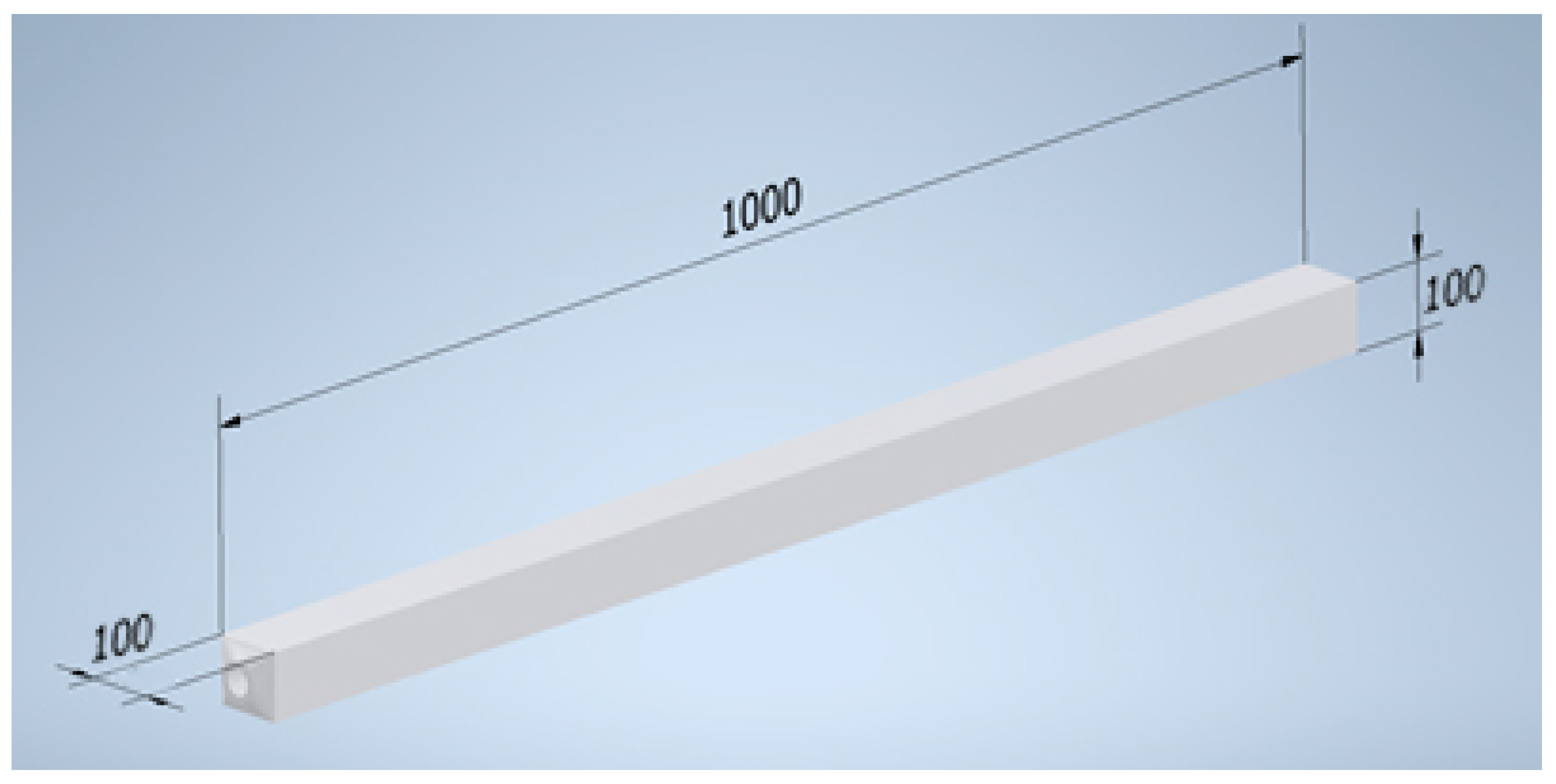
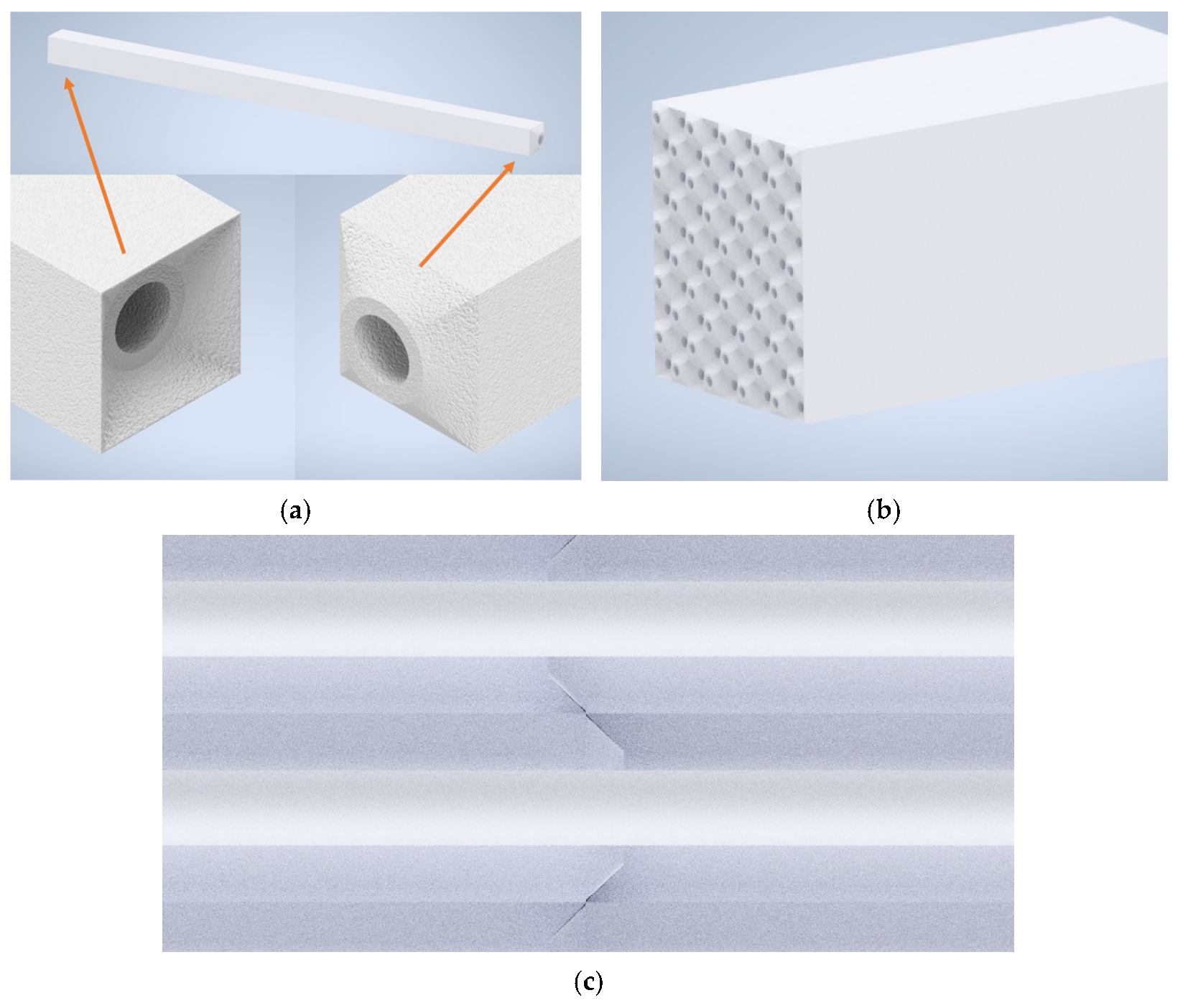
To address the challenges presented in Section 4, a new concrete TES design performed in Autodesk inventor [27] is presented in this paper. The new concept is designed to work with air as the HTF, and it is based on concrete blocks measuring 100 mm × 100 mm × 1000 mm (Figure 3) with a modular design and simple direct-fit male-female connections (Figure 4a). The blocks were designed to be stacked (Figure 4b) and interlocked (Figure 4c) to fit the thermal needs of the installation and the available space. To address challenge (i), the design is based on a modular concept with blocks of relatively small dimensions that allow them to be produced in a controlled industrial environment and then transported to the installation site. Moreover, to overcome challenge (ii), the design is made exclusively in concrete, eliminating the need for metal piping and thus the problem of thermal expansion differences between materials. Challenge (iii) will be addressed in future work by modifying the thermophysical properties of the simulated concrete using new materials currently being validated at an experimental level. Finally, the temperature limitation of molten salts and thermal oils, and their migration into the concrete due to the non-use of metal pipes (challenges (iv) and (v)) are solved by using air as the HTF.
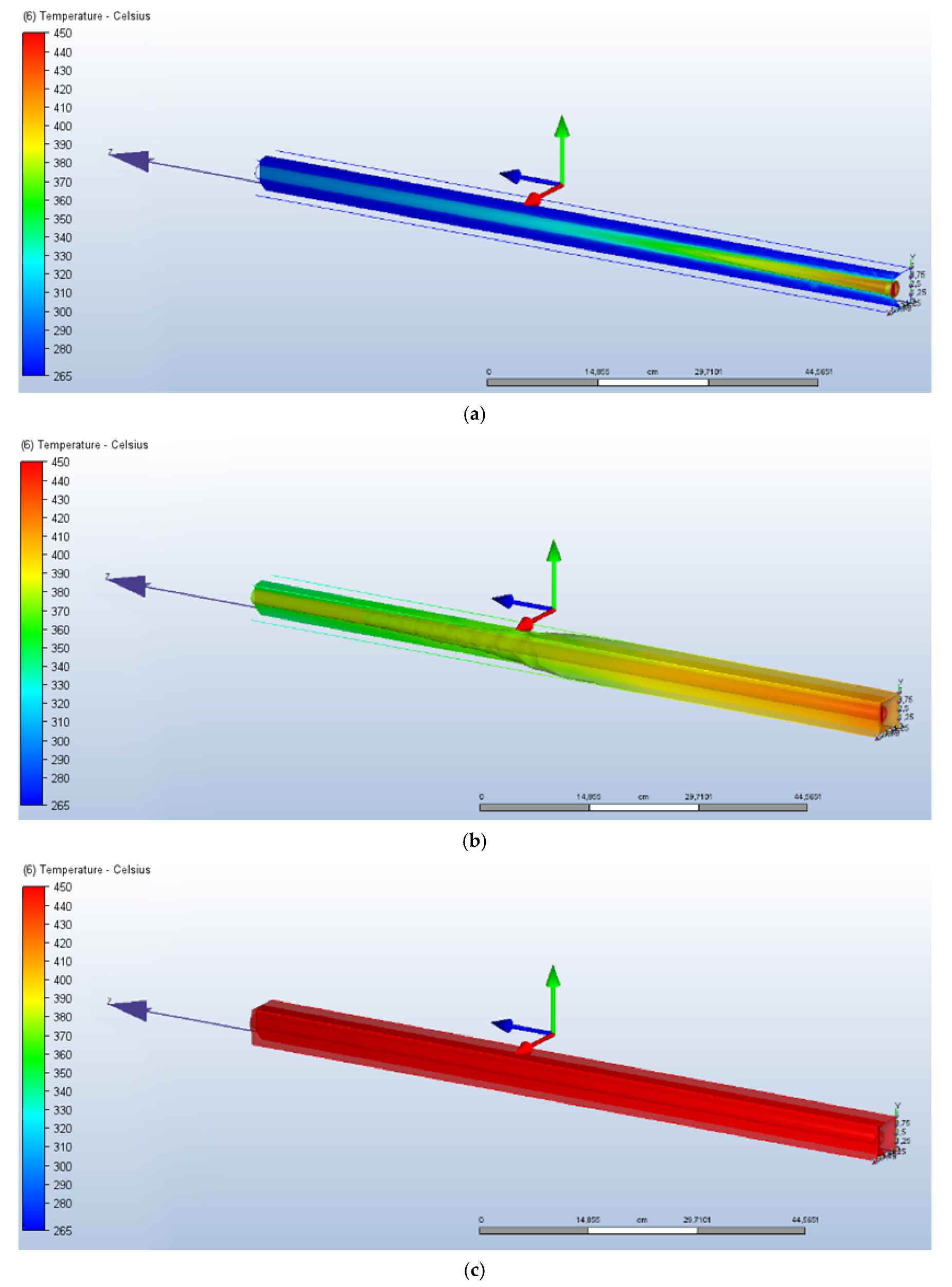
A computational fluid dynamics (CFD) model of the proposed concrete block was developed in Autodesk CFD [28] to validate its feasibility in terms of thermal performance during operation of the module (Figure 5). As a preliminary study, conventional concrete was used. The thermophysical properties of the concrete and heat transfer fluid (air) used are shown in Table 3 and Table 4, respectively. Moreover, the equations governing fluid flow and heat transfer are the Navier–Stokes equations and the first law of thermodynamics, respectively. A k-epsilon turbulence model was selected with a turbulent laminar ratio of 100, and finite element discretisation was performed using “ADV 5: Modified Petrov–Galerkin”. Finally, the mesh dimensions were set to automatic with the parameters set out in Table 5.
The analysis was carried out by performing a complete charging process on a concrete block. The process started with the block at an initial temperature of 265 °C, simulating a real storage cycle, and injecting HTF at 450 °C and 0.33 m3/s (optimised for improved air transfer coefficient) until the concrete block was fully charged (Figure 5). The figure shows that the concrete block reached 450 °C homogeneously, where the difference between the inlet section and the outlet section of the module was about 50 °C in the middle of the charging period (Figure 5b). The total energy stored in the concrete block was 4266 kJ (1.185 kWh).

6. Conclusions and Future Work

High temperature thermal energy storage has shown great potential for increasing the penetration of renewable energies in the energy mix. The use of concrete represents a viable option due to its versatility, relatively low cost, and the ability to reach an operating temperature above 500 °C. However, to become technologically and economically feasible, concrete storage systems must overcome a number of challenges.
This paper, through a comprehensive literature review, identified and analysed the five key issues that affect current systems. These are: (i) in-situ construction, (ii) different thermal expansion coefficient of steel and concrete, (iii) poor thermal conductivity of concrete, (iv) HTF thermal oil or molten salts with limited operating temperature range, and (v) migration of oil/salt by direct contact with the concrete.
Considering the challenges identified, a novel design for a high temperature thermal energy storage system with concrete was proposed and analysed using CFD techniques. The new design is composed of modular concrete blocks with direct-fit male-female connections. These were designed to be stacked and interlocked, thus enabling quick and easy customised sizing according to energy needs. The proposed design was able to overcome four of the five challenges identified. Only the low conductivity of concrete remains to be addressed in future works. In addition, the plug-and-play design facilitates construction of the modules, which can be manufactured under controlled conditions, guaranteeing the properties of the concrete.
Moreover, the streamlined design of the modules, the abundance of the material used, the potential low manufacturing cost once implemented on an industrial scale, as well as the results of the simulations favour the proposed design as a highly competitive thermal energy storage solution. However, this new design also presents new challenges that must be overcome, such as the low specific heat capacity and convective heat transfer coefficient when air is used as the heat transfer fluid, the tight junction between modules, and the interaction of concrete debris with the HTF.
Future work will address the following topics: analysis of the proposed design with other concrete formulations or the addition of aggregates to increase the thermal conductivity of the storage material while maintaining specific heat values; optimise the design to improve the coefficient of internal convection to overcome the low conductivity of air when air is used as the HTF; and analysis of the connection between the modules and the heat supply/demand.

Author Contributions

Conceptualization, D.V. and L.F.C.; methodology, D.V., G.Z., E.B., C.P. and L.F.C.; software, D.V.; validation, G.Z., C.P. and L.F.C.; formal analysis, D.V., E.B. and L.F.C.; investigation, D.V., E.B. and L.F.C.; resources, L.F.C.; data curation, G.Z.; writing—original draft preparation, D.V., E.B. and L.F.C.; writing—review and editing, D.V., G.Z., E.B., C.P. and L.F.C.; visualization, D.V.; supervision, C.P. and L.F.C.; project administration, L.F.C.; funding acquisition, L.F.C. All authors have read and agreed to the published version of the manuscript.

Funding

This work is part of PCI2020-120695-2 project funded by Ministerio de Ciencia e Innovación—Agencia Estatal de Investigación (MCIN/AEI/10.13039/501100011033) and by the European Union “NextGenerationEU/PRTR”. This work was partially funded by the Ministerio de Ciencia, Innovación y Universidades de España (RTI2018-093849-B-C31—MCIU/AEI/FEDER, UE) and by the Ministerio de Ciencia, Innovación y Universidades—Agencia Estatal de Investigación (AEI) (RED2018-102431-T).

Institutional Review Board Statement

Not applicable.

Informed Consent Statement

Not applicable.

Data Availability Statement

Data available from the correspondence author upon request.

Acknowledgments

The authors at University of Lleida would like to thank the Catalan government for quality accreditation (2017 SGR 1537). GREiA is a certified TECNIO agent in the category of technology developers from the government of Catalonia. This work is partially supported by ICREA under the ICREA Academia programme.

Conflicts of Interest

The authors declare no conflict of interest.

References

  1. Cabeza, L.F. 2-Advances in thermal energy storage systems: Methods and applications. In Advances in Thermal Energy Storage Systems; Elsevier: Amsterdam, The Netherlands, 2021; pp. 37–54. [Google Scholar] [CrossRef]
  2. Crespo, A.; Barreneche, C.; Ibarra, M.; Platzer, W. Latent thermal energy storage for solar process heat applications at medium-high temperatures—A review. Sol. Energy 2019, 192, 3–34. [Google Scholar] [CrossRef]
  3. Miró, L.; Gasia, J.; Cabeza, L.F. Thermal energy storage (TES) for industrial waste heat (IWH) recovery: A review. Appl. Energy 2016, 179, 284–301. [Google Scholar] [CrossRef] [Green Version]
  4. Miró, L.; McKenna, R.; Jäger, T.; Cabeza, L.F. Estimating the industrial waste heat recovery potential based on CO2 emissions in the European non-metallic mineral industry. Energy Effic. 2018, 11, 427–443. [Google Scholar] [CrossRef] [Green Version]
  5. REN21. Renewables 2020 Global Status Report; REN21: Paris, France, 2020. [Google Scholar]
  6. González-Roubaud, E.; Pérez-Osorio, D.; Prieto, C. Review of commercial thermal energy storage in concentrated solar power plants: Steam vs. molten salts. Renew. Sustain. Energy Rev. 2017, 80, 133–148. [Google Scholar] [CrossRef]
  7. Fernández, A.G.; Gomez-Vidal, J.; Oró, E.; Kruizenga, A.; Solé, A.; Cabeza, L.F. Mainstreaming commercial CSP systems: A technology review. Renew. Energy 2019, 140, 152–176. [Google Scholar] [CrossRef]
  8. Laing-Nepustil, D.; Zunft, S. 4-Using concrete and other solid storage media in thermal energy storage systems. In Advances in Thermal Energy Storage Systems; Elsevier: Amsterdam, The Netherlands, 2021; pp. 83–110. [Google Scholar] [CrossRef]
  9. Laing, D.; Lehmann, D.; Fi, M.; Bahl, C. Test results of concrete thermal energy storage for parabolic trough power plants. J. Sol. Energy Eng. Trans. ASME 2009, 131, 0410071-6. [Google Scholar] [CrossRef] [Green Version]
  10. Boquera, L.; Castro, J.R.; Pisello, A.L.; Fabiani, C.; D’Alessandro, A.; Ubertini, F.; Cabeza, L.F. Thermal and mechanical performance of cement paste under high temperature thermal cycles. Sol. Energy Mater. Sol. Cells 2021, 231, 111333. [Google Scholar] [CrossRef]
  11. Alonso, M.C.; Vera-Agullo, J.; Guerreiro, L.; Flor-Laguna, V.; Sanchez, M.; Collares-Pereira, M. Calcium aluminate based cement for concrete to be used as thermal energy storage in solar thermal electricity plants. Cem. Concr. Res. 2016, 82, 74–86. [Google Scholar] [CrossRef]
  12. Laing, D.; Steinmann, W.-D.; Tamme, R.; Richter, C. Solid media thermal storage for parabolic trough power plants. Sol. Energy 2006, 80, 1283–1289. [Google Scholar] [CrossRef]
  13. Lucio-Martin, T.; Roig-Flores, M.; Izquierdo, M.; Alonso, M.C. Thermal conductivity of concrete at high temperatures for thermal energy storage applications: Experimental analysis. Sol. Energy 2021, 214, 430–442, Erratum in Sol. Energy 2021, 220, 1137–1138. [Google Scholar] [CrossRef]
  14. Roig-Flores, M.; Lucio-Martin, T.; Alonso, M.C.; Guerreiro, L. Evolution of thermo-mechanical properties of concrete with calcium aluminate cement and special aggregates for energy storage. Cem. Concr. Res. 2021, 141, 106323. [Google Scholar] [CrossRef]
  15. Miliozzi, A.; Dominici, F.; Candelori, M.; Veca, E.; Liberatore, R.; Nicolini, D.; Torre, L. Development and Characterization of Concrete/PCM/Diatomite Composites for Thermal Energy Storage in CSP/CST Applications. Energies 2021, 14, 4410. [Google Scholar] [CrossRef]
  16. Rahjoo, M.; Goracci, G.; Martauz, P.; Rojas, E.; Dolado, J.S. Geopolymer Concrete Performance Study for High-Temperature Thermal Energy Storage (TES) Applications. Sustainability 2022, 14, 1937. [Google Scholar] [CrossRef]
  17. Laing, D.; Steinmann, W.-D.; Fiß, M.; Tamme, R.; Brand, T.; Bahl, C. Solid Media Thermal Storage Development and Analysis of Modular Storage Operation Concepts for Parabolic Trough Power Plants. J. Sol. Energy Eng. 2008, 130, 011006. [Google Scholar] [CrossRef]
  18. Ktistis, P.K.; Agathokleous, R.A.; Kalogirou, S.A. Experimental performance of a parabolic trough collector system for an industrial process heat application. Energy 2021, 215, 119288. [Google Scholar] [CrossRef]
  19. Martins, M.; Villalobos, U.; Delclos, T.; Armstrong, P.; Bergan, P.G.; Calvet, N. New Concentrating Solar Power Facility for Testing High Temperature Concrete Thermal Energy Storage. Energy Procedia 2015, 75, 2144–2149. [Google Scholar] [CrossRef] [Green Version]
  20. Hoivik, N.; Greiner, C.; Barragan, J.; Iniesta, A.C.; Skeie, G.; Bergan, P.; Blanco-Rodriguez, P.; Calvet, N. Long-term performance results of concrete-based modular thermal energy storage system. J. Energy Storage 2019, 24, 100735. [Google Scholar] [CrossRef]
  21. Prieto, C.; Pérez Osorio, D.; Gonzalez-Roubaud, E.; Fereres, S.; Cabeza, L.F. Advanced Concrete Steam Accumulation Tanks for Energy Storage for Solar Thermal Electricity. Energies 2021, 14, 3896. [Google Scholar] [CrossRef]
  22. Ramos, D.C. El Sistema de Control del Hormigón en la Normativa Española: Evolución y Futuro; Asociación Española de Ingeniería Estructural (ACHE): Madrid, Spain, 2014. [Google Scholar]
  23. Asadi, I.; Shafigh, P.; Abu Hassan, Z.F.B.; Mahyuddin, N.B. Thermal conductivity of concrete—A review. J. Build. Eng. 2018, 20, 81–93. [Google Scholar] [CrossRef]
  24. Vignarooban, K.; Xu, X.; Arvay, A.; Hsu, K.; Kannan, A.M. Heat transfer fluids for concentrating solar power systems—A review. Appl. Energy 2015, 146, 383–396. [Google Scholar] [CrossRef]
  25. Prieto, C.; Ruiz-Cabañas, F.J.; Rodríguez-Sanchez, A.; Rubio Abujas, C.; Fernández, A.I.; Martínez, M.; Oró, E.; Cabeza, L.F. Effect of the impurity magnesium nitrate in the thermal decomposition of the solar salt. Sol. Energy 2019, 192, 186–192. [Google Scholar] [CrossRef]
  26. Bilal Awan, A.; Khan, M.N.; Zubair, M.; Bellos, E. Commercial parabolic trough CSP plants: Research trends and technological advancements. Sol. Energy 2020, 211, 1422–1458. [Google Scholar] [CrossRef]
  27. Autodesk. Autodesk Inventor. 2022. Available online: https://www.autodesk.es/products/inventor/overview (accessed on 19 May 2022).
  28. Autodesk. Autodesk CFD. 2022. Available online: https://www.autodesk.com/products/cfd/overview (accessed on 19 May 2022).
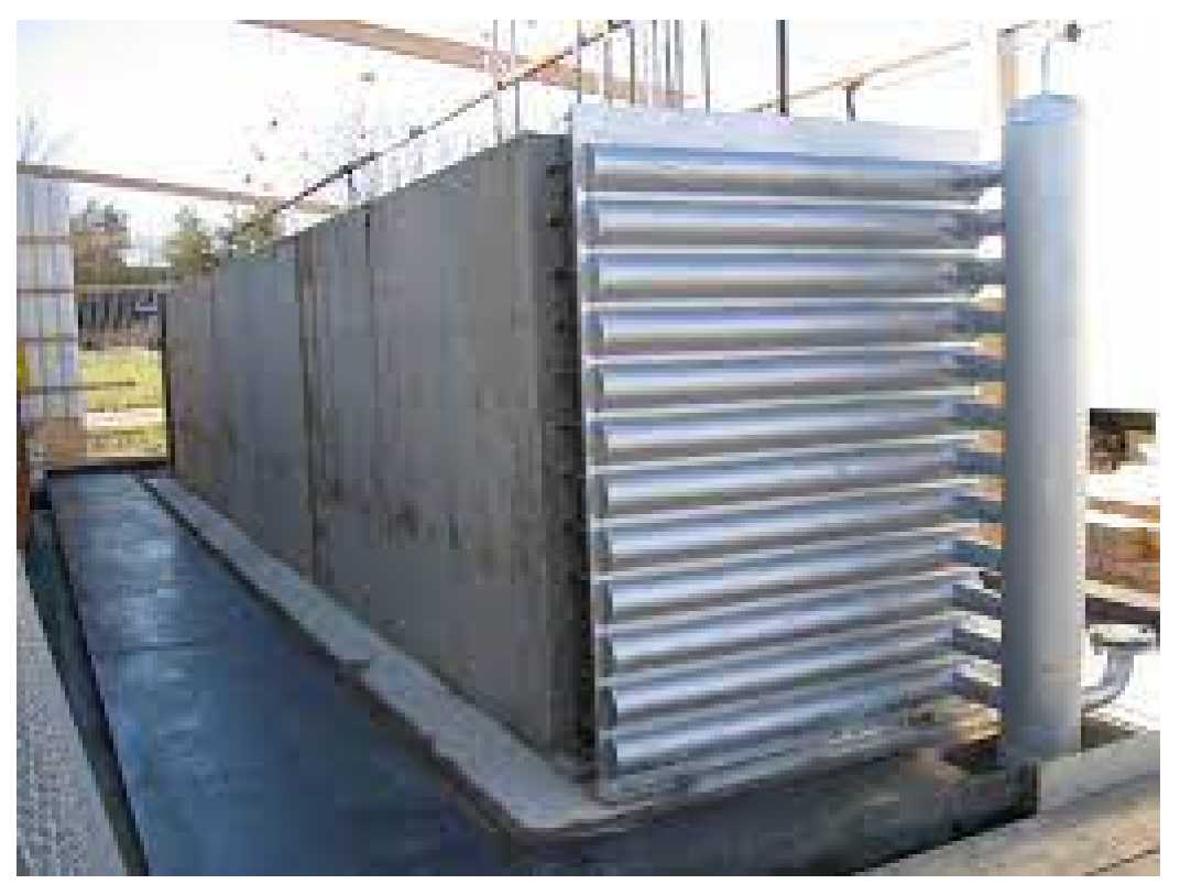
Figure 1. DLR concrete storage concept. Reprinted/adapted with permission from Ref. [9]. 2009, American Society of Mechanical Engineers.
Energies 15 04544 g001
Figure 2. Concrete thermal element design for the HEATCRETE vp1 concept [20].
Energies 15 04544 g002
Figure 3. Concept of concrete block and block dimensions [mm].
Energies 15 04544 g003
Figure 4. Concrete block concept: (a) fitting connections, (b) stacked distribution example, (c) connection points.
Energies 15 04544 g004
Figure 5. Computational fluid dynamics of the proposed concrete block: (a) initial charge, (b) mid-charge, (c) full charge.
Energies 15 04544 g005
Table 1. Summary of innovative concrete formulations for high temperature TES.
FormulationCementWater-Cement RatioSandAggregateSuper-
Plasticizer
Curing And Drying ProtocolThermal CyclingCompression Strength (MPa)PorosityThermal PropertiesReference
Cement pasteOPC0.34---------28 days curing in water20–200 °C
20–400 °C
20–600 °C
20–800 °C
Loss of stability in thermal cycling above 400 °COpen porosity decreases with thermal cyclesDecrease in the thermal conductivity from 1 W/m·K to around 0.5 W/m·K after thermal cycling[10]
Cement pasteCAC0.34---------28 days curing in water20–200 °C
20–400 °C
20–600 °C
20–800 °C
Decrease after first thermal cycle with stabilisation later onOpen porosity increased with temperature and thermal cyclingLower thermal conductivity than OPC but higher heat capacity[10]
Mortar70% CAC + 30% blast furnace slag (BFS)0.44Standard siliceous---1%3 days @105 °C290–550 °C72.67 ± 1.97 (after 7 days curing)------[11]
ConcreteBlast furnace cement------Iron oxides, flue ash, and other---------Medium material strength with several cracks---916 J/kg·K (@350 °C)
1.0 W/m·K (@350 °C)
9.3 ·10−6/K (@350 °C)
[12]
Concrete70% CAC + 30% blast furnace slag (BFS)0.5Standard siliceousNatural from crash stone, silicon calcareous aggregate (SCA)0.8%3 days @105 °C290–550 °C50% decrease after first thermal cycle with stabilisation later on100% increase after thermal cycles---[11]
Concrete70% CAC + 30% blast furnace slag (BFS)0.57Standard siliceousNatural SCA + industrial waste slag0.8%3 days @105 °C290–550 °C50% decrease after first thermal cycle with stabilisation later on100% increase after thermal cycles---[11]
ConcreteCAC0.43---Basalt 0–6 mm0.9%Left @95% RH and @20 °C until testing300–600 °C------1.2–2 W/m·K
Decrease of 20–40% in the thermal conductivity after first thermal cycle
[13]
ConcreteCAC0.43---CAT 0.25–4 mm0.9%Left @95% RH and @20 °C until testing300–600 °C------1.2–2 W/m·K
Decrease of 20–40% in the thermal conductivity after first thermal cycle
[13]
ConcreteCAC0.43---Slag 0.25–2 mm0.9%Left @95% RH and @20 °C until testing300–600 °C------1.2–2 W/m·K
Decrease of 20–40% in the thermal conductivity after first thermal cycle
[13]
ConcreteCAC0.43---Slat 3–7 mm0.9%Left @95% RH and @20 °C until testing300–600 °C------1.2–2 W/m·K
Decrease of 20–40% in the thermal conductivity after first thermal cycle
[13]
ConcreteCAC0.43---Calcareous 0–6 mm0.9%Left @95% RH and @20 °C until testing300–600 °C------1.2–2 W/m·K
Decrease of 20–40% in the thermal conductivity after first thermal cycle
[13]
ConcreteCAC0.43---Siliceous 0–3 mm0.9%Left @95% RH and @20 °C until testing300–600 °C------Up to 5 W/m·K
Decrease of 50% in the thermal conductivity after first thermal cycle
[13]
ConcreteCAC0.43---Siliceous + polypropylene fibres1%Left @95% RH and @20 °C until testing300–600 °CLoss of 74% after one thermal cycle---Decrease of 50% in the thermal conductivity after first thermal cycle[14]
ConcreteCAC0.43---Calcium aluminate (CAT) + polypropylene fibres1%Left @95% RH and @20 °C until testing300–600 °CLoss of 63% after one thermal cycle1.6–2 µm
Increase to 24–27 µm after thermal cycling
Decrease of 50% in the thermal conductivity after first thermal cycle[14]
ConcreteCAC0.43---CAT + crushed basalt + polypropylene fibres1%Left @95% RH and @20 °C until testing300–600 °CLoss of 69% after one thermal cycle0.7 µm
Increase to 24–27 µm after thermal cycling
Decrease of 50% in the thermal conductivity after first thermal cycle[14]
ConcreteCAC0.43---CAT + crushed basalt + 15% waste slag + polypropylene fibres1%Left @95% RH and @20 °C until testing300–600 °CLoss of 69% after one thermal cycle1.6–2 µm
Increase to 24–27 µm after thermal cycling
Decrease of 50% in the thermal conductivity after first thermal cycle[14]
ConcreteCAC0.43---CAT + crushed basalt + 30% waste slag + polypropylene fibres1%Left @95% RH and @20 °C until testing300–600 °CLoss of 61% after 1 thermal cycle1.6–2 µm
Increase to 24–27 µm after thermal cycling
Decrease of 50% in the thermal conductivity after first thermal cycle[14]
ConcreteCement0.329% washed sand 0-4 mmAggregate + metal and synthetic fibres0.43%28 days in a tank @100% HR and @15-20 °C50–200 °C
50–300 °C
50–400 °C
(1 cycle)
Higher values at low temperatureDensity was characterisedSpecific heat is constant with temperature treatment
Thermal conductivity around 2 W/m·K
[15]
Concrete/PCMCement0.37-0.419% washed sand 0-4 mmAggregate + metal and synthetic fibres + PCM impregnate in porous material0.43%28 days in a tank @100% HR and @15-20 °C50–200 °C
50–300 °C
50–400 °C
(1 cycle)
PCM content helps in maintaining higher values after thermal treatmentDensity was characterisedSpecific heat increases with temperature treatment
Thermal conductivity decreases strongly with PCM content
[15]
Geopolymer concrete20% OPC + 80% inorganic geopolymer0.6---Steel slag---1 day @100% RH +
28 days @room temperature
---------More stable thermal properties than OPC as temperature increases[16]
Table 2. Thermophysical properties of heat transfer fluids used in CSP plants [24,26].
HTFMelting Point (°C)Stability Limit (°C)Viscosity (Pa·s)Thermal Conductivity (W/m·K)Heat Capacity (kJ/kg·K)
Air------0.00003 (@ 600 °C)0.06 (@ 600 °C)1.12 (@ 600 °C)
Water/steam0---0.00133 (@ 600 °C)0.08 (@ 600 °C)2.42 (@ 600 °C)
Thermal oils−20300---~0.1---
Mineral oil−20350---~0.1---
Synthetic oil−20400---~0.1---
Biphenyl/diphenyl oxide123930.00059 (@ 300 °C)~0.01 (@ 300 °C)1.93 (@ 300 °C)
Solar salt (60 wt.% NaNO3-40 wt.% KNO3)2206000.00326 (@ 300 °C)0.55 (@ 400 °C)1.1 (@ 600 °C)
Table 3. Thermophysical properties of concrete implemented in CFD.
PropertyConcrete
Thermal conductivity x, y, z direction [W/m·K]1.01
Density [kg/m3]2306
Specific heat [kJ/kg·K]0.837
Emissivity [-]0.95
Transmissivity [-]0
Electrical resistivity [ohm·m]0
Wall roughness0
Table 4. Thermophysical properties of the HTF (air) implemented in CFD.
PropertyAir
DensityEquation of state
Viscosity [poise]0.0001817
Thermal conductivity [W/m·K]0.02563
Specific heat [kJ/kg·K]1.004
Compressibility [Cp/Cv]1.4
Emissivity1
Wall roughness0
Table 5. CFD mesh parameters.
ParameterValue
Resolution factor1
Edge growth rate1.1
Minimum points on edge2
Points on longest edge10
Surface limiting aspect ratio20
Publisher’s Note: MDPI stays neutral with regard to jurisdictional claims in published maps and institutional affiliations.