1. Introduction
Grounding devices of transmission line towers are the most important lightning protection facilities [
1,
2]. The contradiction between the corridors of transmission lines and land resources has become increasingly significant with the development of the power system [
3,
4]. Therefore, the use of reinforced concrete foundations as part of grounding electrodes has been considered for a long time [
5]. It improves the current dispersion characteristics and plays an effective role in reducing grounding resistance [
6,
7,
8,
9].
Grounding resistance is a key parameter to characterize the grounding device. In order to evaluate the role of the tower foundation, simplified formulas for estimating the grounding resistance were proposed under the assumption that the concrete resistivity is the same as that of the soil [
10]. The utilization coefficients of the formulas for calculating grounding resistance of transmission tower grounding devices were summarized [
11]. In order to consider the effect of reinforced concrete on the grounding resistance, a whole metal electrode was used to replace the foundation for calculation [
12]. The accuracy of the above methods is affected by foundation structures and concrete resistivities. Therefore, they are not applicable in complex situations.
The finite element method can accurately calculate the electric field around the foundation [
13,
14]. However, due to the complex structure of the reinforced concrete foundation, establishment of the simulation model for one pile is troublesome and the computation is extensive, not to mention that usually the foundation consists of several piles. The grounding resistance of the cylindrical conductor can be quickly calculated by the method of moments even if the structure is complex [
15,
16,
17]. For this reason, some methods to equate non-cylindrical electrode to cylindrical electrodes have been proposed in order to use the method of moments to calculate grounding resistance. For example, flat conductor is equivalent to cylindrical conductor by the method of equal cross-sectional area [
18], in which the equivalent radius
is given by
, where
is the cross-sectional side length of the grounding electrode. The equal cross-sectional perimeter method that fully considers the contact resistance between the foundation and the soil was also introduced, with which the equivalent radius is given by
[
19]. Based on the same idea, Pan et al. proposed a method to equate cylindrical reinforced concrete foundation into a cylindrical conductor so that the grounding resistance can be obtained by the method of moments, which simplified the calculation [
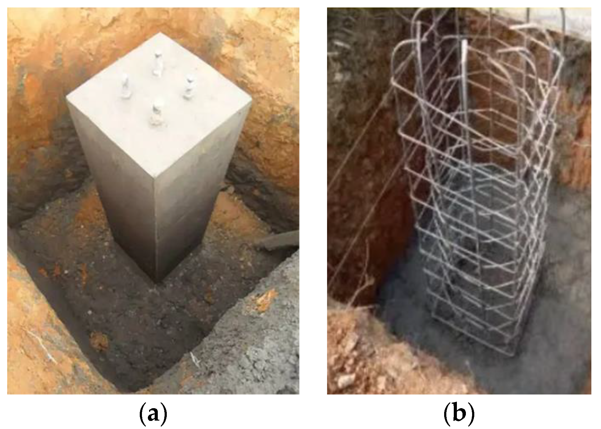
20]. However, the calculation for grounding resistance of square-column reinforced concrete foundation, as shown in
Figure 1, has not been developed. How to equate the reinforced concrete foundation into a cylindrical conductor has become the key to simplify the calculation.
In order to calculate the grounding resistance of the square-column reinforced concrete foundation effectively and accurately, a method to equate the foundation into a cylindrical conductor is presented based on the finite element method simulation, and then the grounding resistance is calculated by the method of moments. In addition, the equal cross-sectional area method and the equal cross-sectional perimeter method to estimate the equivalent radius are also analyzed. The applicability of the two methods is presented.
2. Theoretical Background
The principle of the method proposed in this paper can be determined by the relationship between the reinforced concrete foundation parameters and the grounding impedance. As shown in
Figure 2, the injected current flows forward along the foundation and dissipates into the ground. The grounding impedance includes the dispersion resistance
and the longitudinal impedance
.
is the equivalent resistance from the foundation surface to infinity, which is not only related to the length of the foundation, but also to the shape and size of the cross-section.
is given by:
where
is related to the effective area of current flow under the influence of skin effect. The internal impedance
of square conductors can only be calculated by numerical method without corresponding formula and for cylindrical conductors,
is given by:
where
is the conductivity of the conductor,
is the magnetic permeability of the conductor,
is the radius of the conductor,
is the length of the conductor and
and
are the modified zero-order and first-order Bessel functions.
The external inductance is formed by the magnetic flux generated by the current flowing through the grounding electrode, which is mainly affected by the radius of the grounding electrode and the soil magnetic permeability.
The equivalent method can be used only when and of the equivalent cylindrical conductor are consistent with those of the original reinforced concrete foundation.
3. Calculation Processes
The calculation of the equivalent radius is based on the principle that the dispersion resistance keeps the same. The corresponding equivalent resistivity and relative magnetic permeability of the equivalent electrode are analyzed by keeping the longitudinal impedance the same.
3.1. Equivalent Radius of the Square-Column Reinforced Concrete Foundation
When calculating the equivalent radius, the dispersion resistance per unit length needs to be obtained. The square-column reinforced concrete foundation is regarded as an infinitely long conductor, which can be simulated by a 2D finite element method. Three typical reinforced concrete foundations A, B and C are selected, with the foundation cross-sectional dimensions of 0.8 m × 0.8 m, 1.0 m × 1.0 m and 1.2 m × 1.2 m, and the heights are 3.6 m, 4.4 m and 5.0 m, respectively. The main rebars consist of sixteen steel rebars with a diameter 22 mm located 50 mm below the surface of the foundation.
A cylinder with a radius of one hundred times the side length of the cross-section is taken as the calculation area. This radius is large enough that the equipotential lines are consistent with the cylinder. Then
is equivalent to the series connection of the resistance from the reinforced concrete foundation to the cylinder and the resistance from the cylinder to infinity. Since the resistance from the cylinder to infinity is not affected by the shape of the foundation cross-section, just the resistance from the reinforced concrete foundation to the cylinder needs to be calculated, which can be precisely calculated by the finite element method. Then, the equivalent radius
of the reinforced concrete foundation can be obtained by the following formula:
where
is the soil resistivity in Ω·m;
is the radius of the cylinder in mm;
is the resistance between the foundation and the cylinder.
Figure 3 shows the equivalent radius of the pile foundation when the ratio of concrete resistivity to soil resistivity is taken as the control parameter. It can be seen that the equivalent radius decreases as the ratio of concrete resistivity to soil resistivity increases. The equivalent radius of the square-column reinforced concrete foundation satisfies the following relation:
where
is the cross-sectional side length in m;
is the ratio of concrete resistivity to soil resistivity.
3.2. Analysis of Equivalent Resistivity and Relative Magnetic Permeability Corresponding to the Equivalent Electrode
Considering the uneven current distribution under skin effect, it is necessary to analyze the longitudinal impedance of reinforced concrete foundation at different frequencies to determine the resistivity and relative magnetic permeability of the equivalent model. As shown in
Table 1, the longitudinal impedance is measured in mΩ·m
-1 due to the large cross-sectional size of the pile foundation. Compared with the dissipation resistance
, the longitudinal impedance results of the three pile foundations from 50 Hz to 100 kHz are small. Therefore, it is accepted that only the dispersion resistance needs to be considered in the equivalent calculation. The resistivity and relative magnetic permeability of the equivalent model can take the parameters of the steel rebar.
4. Results and Discussion
The method proposed in this paper is compared with the equal cross-sectional area method and the equal cross-sectional perimeter method. The influence of various factors on the equivalent radius and grounding resistance results is analyzed to determine the applicability of each method.
4.1. Influence of Different Equivalent Methods on the Calculation Result of Power Frequency Grounding Resistance
The equivalent radius of the square-column reinforced concrete foundation is calculated by the equal cross-sectional area method and the equal cross-sectional perimeter method. As shown in
Table 2, when the ratio of concrete resistivity to soil resistivity is high, the equivalent radius calculated by the method proposed in this paper is quite different from that of the other two methods.
According to the equivalent radius of the pile foundation obtained by the three methods above, CDEGS is used to calculate the power frequency grounding resistance under different soil resistivities. The results are shown in
Table 3,
Table 4 and
Table 5.
The power frequency grounding resistance obtained by the three equivalent methods is compared with the grounding resistance of the reinforced concrete foundation, and the results are shown in
Figure 4.
It can be seen that the errors of the equal cross-sectional area method and the equal cross-sectional perimeter method increase with the higher ratio of concrete resistivity to soil resistivity. As mentioned in
Section 3.1, the equivalent radius is closely related to the dispersion resistance. When the two simplified methods are applied to the calculation of reinforced concrete foundation, a fixed equivalent radius is adopted without considering the influence of dispersion resistance. Each method will make the error less than 10% in the following cases: The equal cross-sectional area method is applicable when the concrete resistivity is within twice the soil resistivity; The equal cross-sectional perimeter method is applicable when the concrete resistivity is approximately same or less than the resistivity of the soil.
The method proposed in this paper fully takes into account the effect of dispersion resistance and finds the corresponding equivalent radius with different concrete resistivities and soil resistivities, which can ensure sufficient accuracy.
4.2. Influence of the Number of Main Rebars on Power Frequency Grounding Resistance
Considering that the density of main rebars may affect the results, the equivalent radius of the pile foundation with 24 main rebars is calculated and compared with the results in
Figure 3.
As shown in
Figure 5, the density of main rebars has a great influence on the equivalent radius results when the ratio of concrete resistivity to soil resistivity is high. Calculate the power frequency grounding resistance of two types of the pile foundation A with sixteen and twenty-four main rebars at the concrete resistivity to soil resistivity ratio of fifteen. The equivalent radii of the two types of foundations are 46.5 mm and 74.3 mm, respectively. The results are shown in
Table 6.
It can be seen that even though the pile foundation A with different numbers of main rebars may have large differences in equivalent radius at higher concrete resistivity to soil resistivity ratios, the effect on the grounding resistance results is not significant. Considering that the equivalent radius is measured in millimeter, Formula (4) applies when the ratio of concrete resistivity to soil resistivity is less than six.
4.3. Calculation Results
Usually the foundation consists of four piles, and the distance between the piles under different voltage levels is shown in
Table 7.
The power frequency grounding resistance of tower foundation with four piles under different voltage levels is calculated. The resistivity of concrete here is taken as 100 Ω·m and the equivalent radius of the pile foundation A under different soil resistivities is obtained from
Section 3.1. The results are shown in
Table 8.
5. Calculation and Analysis of Impulse Grounding Resistance
Reducing impulse grounding resistance of grounding devices is an effective method to avoid lightning accidents on transmission lines. Considering the skin effect and the effective dispersion length at high frequency, the transient performance of grounding device under impulse current may be different from that under power frequency. The inductance hinders the current flowing to the far end of the grounding electrode and the dissipation effect is significantly weakened when the grounding electrode exceeds the effective length. Therefore, it is necessary to calculate and analyze the impulse grounding resistance of reinforced concrete foundation under lightning impulse.
CDEGS is used to calculate the impact transient response of reinforced concrete foundation under the 2.6/50 μs lightning current waveform. The calculation processes of impulse grounding resistance are as follows: fast Fourier transform (FFT) is performed to decompose the time-domain signal into multiple frequency-domain signals. The electromagnetic field value at each frequency is calculated and the time domain response is obtained by inverse Fourier transform. Finally, the impulse grounding resistance is obtained by the calculation between the ground potential rise (GPR) and the injected lightning current.
As shown in
Table 9, the power frequency and impulse grounding resistance of pile foundation A are calculated and the concrete resistivity is taken as 15 Ω·m. The results of the impulse grounding resistance of tower foundation with four piles are shown in
Table 10.
It can be seen that the results of two types of grounding resistance are basically the same. Therefore, the equivalent method proposed in this paper is also applicable to the impulse situation.
6. Conclusions
A simplified calculation method is proposed to calculate the grounding resistance of the reinforced concrete foundation. The correlation between the equivalent radius, the cross-sectional side length of the foundation, the concrete resistivity and the soil resistivity is investigated. Conclusions are as follows:
- (1)
The square-column reinforced concrete foundation is replaced by a cylindrical conductor with the radius given by the expression (4), which is applicable when the concrete resistivity is within six times of the soil resistivity.
- (2)
The longitudinal impedance of the foundation can be ignored when performing the equivalent calculation. The equivalent cylindrical model adopts the parameters of steel rebars.
- (3)
The equal cross-sectional area method is applicable when the concrete resistivity is within twice the soil resistivity. The equal cross-sectional perimeter method is applicable when the concrete resistivity is approximately same or less than the resistivity of the soil. The method proposed in this paper can ensure sufficient accuracy under the conditions of different concrete resistivities and soil resistivities.
- (4)
Usually the length of the square-column reinforced concrete foundation is three meters to five meters. Within this length, the power frequency and impulse grounding resistances are almost the same. The equivalent method proposed in this paper is also applicable to the impulse situation.
Author Contributions
Conceptualization, B.D. and B.Z.; methodology, B.D. and B.Z.; software, B.D.; validation, B.D., Y.T. and R.L.; formal analysis, B.D.; investigation, R.L.; resources, Y.T. and R.L.; data curation, B.D.; writing—original draft preparation, B.D.; writing—review and editing, B.Z.; visualization, B.Z.; supervision, B.Z. and Y.T.; project administration, B.Z.; funding acquisition, B.Z. All authors have read and agreed to the published version of the manuscript.
Funding
This research was funded by the National Natural Science Foundation of China, grant number U1866212.
Institutional Review Board Statement
Not applicable.
Informed Consent Statement
Not applicable.
Data Availability Statement
Not applicable.
Conflicts of Interest
The authors declare no conflict of interest.
References
- Mohamad Nasir, N.A.F.; Ab Kadir, M.Z.A.; Osman, M.; Abd Rahman, M.S.; Amirulddin, U.A.; Mohd Nasir, M.S.; Nur, H.Z.; Nik Ali, N.H. Influence of Lightning Current Parameters and Earthing System Designs on Tower Footing Impedance of 500 kV Lines. Energies 2021, 14, 4736. [Google Scholar] [CrossRef]
- Hizamul-Din, H.H.; Nor, N.M.; Ahmad, N.N.; Idris, N.F.; Mahmud, A. Investigations on the performance of various horizontal ground electrodes. Energies 2021, 14, 1036. [Google Scholar] [CrossRef]
- Noda, M.; Kinoshita, H.; Matsubara, I. A Method of Estimating the Grounding Resistance of Power Transmission Tower Foundation. Electr. Eng. Jpn. 1987, 107, 68–76. [Google Scholar] [CrossRef]
- Visacro, S.; Silveira, F.H. Lightning Performance of Transmission Lines: Methodology to Design Grounding Electrodes to Ensure an Expected Outage Rate. IEEE Trans. Power Deliv. 2015, 30, 237–245. [Google Scholar] [CrossRef]
- Wu, J.; Zhang, B.; He, J.; Zeng, R. Optimal Design of Tower Footing Device with Combined Vertical and Horizontal Grounding Electrodes Under Lightning. Electr. Power Syst. Res. 2014, 113, 188–195. [Google Scholar] [CrossRef]
- Sobolewski, K. Numeric and Measurement Analysis of Earthing Resistance in Layered Soil Including GEM Material. In Proceedings of the 2018 Progress in Applied Electrical Engineering, Koscielisko, Poland, 18–22 June 2018. [Google Scholar]
- Sobolewski, K. Investigations of Ground Enhanced Compounds Resistivity Changes in Time. In Proceedings of the 2020 Progress in Applied Electrical Engineering, Koscielisko, Poland, 21–26 June 2020. [Google Scholar]
- Trifunovic, J.; Kostic, M.B. An Algorithm for Estimating the Grounding Resistance of Complex Grounding Systems Including Contact Resistance. IEEE Trans. Ind. Appl. 2015, 51, 5167–5174. [Google Scholar] [CrossRef]
- Androvitsaneas, V.P.; Gonos, I.F.; Stathopulos, I.A. Experimental Study on Transient Impedance of Grounding Rods Encased in Ground Enhancing Compounds. Electr. Power Syst. Res. 2016, 139, 109–115. [Google Scholar] [CrossRef]
- Sobolewski, K. Modeling and Simulations in the Earthing Calculations. In Proceedings of the 2019 IEEE 20th International Conference on Computational Problems of Electrical Engineering, Lviv, Ukraine, 15–18 September 2019. [Google Scholar]
- Sobolewski, K.; Ciuba, M. Comparative Analysis of Numerical Calculations and Computer Models of Groundings with Using GEM Technology. In Proceedings of the IEEE 2018 34th International Conference on Lightning Protection, Rzeszow, Poland, 2–7 September 2018. [Google Scholar]
- Brandenbursky, V.; Farber, A.; Korj, V.; Braunshtein, A. Ground Resistance Calculation for Small Concrete Foundations. Electr. Power Syst. Res. 2011, 81, 408–413. [Google Scholar] [CrossRef]
- Trifunovic, J.; Kostic, M.B. Quick Calculation of the Grounding Resistance of a Typical 110 kV Transmission Line Tower Grounding System. Electr. Power Syst. Res. 2016, 131, 178–186. [Google Scholar] [CrossRef]
- Faleiro, E.; Asensio, G.; Denche, G.; Moreno, J. A Fast Method to Compute the Grounding Resistance of a Coated Electrode Using the Coated Electrode Equivalent Radius. Int. J. Electr. Power Energy Syst. 2022, 137, 107879. [Google Scholar] [CrossRef]
- Fortin, S.; Mitskevitch, N.; Dawalibi, F.P. Analysis of Grounding Systems in Horizontal Multilayer Soils Containing Finite Heterogeneities. IEEE Trans. Ind. Appl. 2015, 51, 5095–5100. [Google Scholar] [CrossRef]
- Permal, N.; Osman, M.; Ariffin, A.M.; Kadir, M. The Impact of Substation Grounding Grid Design Parameters in Non-Homogenous Soil to the Grid Safety Threshold Parameters. IEEE Access 2021, 9, 37497–37509. [Google Scholar] [CrossRef]
- Liu, Z.; Wang, S.; Zhang, B.; Cao, Y.; Li, W. Method for Reducing Impulse Grounding Impedance of Grounding Device by Using Grounding Electrode with Non-uniform Radius. In Proceedings of the 2020 IEEE International Conference on High Voltage Engineering and Application, Beijing, China, 6–10 September 2020. [Google Scholar]
- Wang, S.; Zhang, B.; Li, M.; Kang, P.; Su, M.M. Probe into Equivalent Radius of Grounding Electrodes with Non-circular Cross Section. Smart Power 2020, 48, 17–24. [Google Scholar]
- Thapar, B.; Ferrer, O. Ground Resistance of Concrete Foundations in Substation Yards. IEEE Trans. Power Deliv. 1990, 5, 130–136. [Google Scholar] [CrossRef]
- Pan, W.; Wang, B.; Quan, R.; Dai, M.; Gu, D. Calculation and Analysis of Grounding Body of Typical Tower Foundation for UHV Power Transmission. Power Syst. Technol. 2013, 37, 679–685. [Google Scholar]
| Publisher’s Note: MDPI stays neutral with regard to jurisdictional claims in published maps and institutional affiliations. |
© 2022 by the authors. Licensee MDPI, Basel, Switzerland. This article is an open access article distributed under the terms and conditions of the Creative Commons Attribution (CC BY) license (https://creativecommons.org/licenses/by/4.0/).


