Abstract
Thailand is an agricultural country with several agro-industrial by-products that can be processed into fuels. Although producing ethanol from agro-industrial by-products is an interesting option, the process of distilling ethanol from fermented agricultural products requires a high temperature to increase the ethanol concentration from 10% to 95%. In this research, solar ethanol distillation equipment incorporating a solar parabolic collector with a vacuum heat absorber tube to increase efficiency by reducing heat loss was designed and developed. An electronic device was used to control the distillation process, maintain the required temperature, and make suitable adjustments to the solar radiation acceptance angles of the parabolic solar collector. Ethanol dilution at concentrations of 10%, 15%, and 20%, and Sato (Thai Rice Wine) were used as the reactant in the distillation process. The result of distilling ethanol distillation with a semi-automatic control using a vacuum-tube parabolic solar collector showed that the thermal efficiency of the receiver was 12.61%, 13.93%, 18.58%, and 17.40%, respectively. The thermal efficiency of the heat exchanger was 11.27%, 10.76%, 13.35%, and 12.35%, respectively. The final concentration of ethanol was 67%, 76%, 82%, and 80%, respectively, and the amount of the distilled ethanol was 330 mL, 352 mL, 398 mL, and 360 mL, respectively.
1. Introduction
In the modern world, energy is essential for transport, industry, and daily life. As the population continues to increase, the higher energy demand has a direct impact on the environment [1,2]. To counter this, focusing on renewable energy should be the key focus of energy technology development in the future. At a regional level, however, energy technology development is largely dependent on the environment and economic conditions of each country, as well as the locally available techniques and expertise in optimizing renewable energy for maximum benefit. Solar energy is the most popular type of renewable energy as it is the most likely to be used commercially. Solar energy also can be converted into other forms of energy such as thermal energy, electrical energy, chemical energy, and mechanical energy [3,4].
Using solar thermal energy to replace electrical energy and fossil fuels is becoming popular in the industry [5]. Electricity generated from solar energy is already popular in many countries such as the United States of America, Spain, Saudi Arabia, India, and China [6]. At present, the total solar energy power generation capacity around the world is 2828.8 MW, of which about 2463.9 MW is under construction. In addition, it is also commonly used in industries such as the automotive, dairy, food, textile, paper, chemical, meat, and plastic industries [7,8]. Generally, solar thermal energy is used in systems that are heated to less than 260 °C [9]. To achieve higher temperatures, concentrating collectors such as a parabolic trough, parabolic dish, or a central receiver tower are used. Temperatures as high as 1000 °C or even higher can be achieved with concentrating collectors [9,10]. Solar towers technology is the future because it can achieve much higher thermodynamic efficiencies than parabolic toughs as a result of having much higher concentration ratios. Heat transfer enhancement for high-temperature PCMs used in solar thermal plants becomes extremely important. For high-temperature thermal storage systems, heat transfer enhancement using porous materials is observed. A significant heat transfer improvement has been observed by embedding molten salts into porous metals or expanded graphite materials [11].
Thailand is a resource-rich agricultural economy with an abundance of agro-industrial by-products that can be converted into fuel energy, such as sugarcane leaves, rice straws, roots, and branches, including cassava rhizomes. Every year, the country produces a total of 36.4 million tons of agro-industrial by-products that could be converted into approximately 329 MJ of thermal energy to generate about 2500 MW of electricity. Producing an equivalent amount of thermal energy and electricity would require approximately 16 million tons of coal and 8200 million liters of fuel oil, respectively. Converting these agro-industrial by-products into energy can help reduce the import of fossil fuel energy and increase the income of local farmers [12,13].
Under Thailand’s plan to use ethanol in the form of E10 fuel as an alternative energy to replace methyl tertiary butyl ether (MTBE) in gasoline 95, the country aimed to produce one million liters per day in 2006 and then increase production to three million liters per day by 2011 [14]. In addition, Thailand has recently implemented the Alternative Energy Development Plan (2015–2036) to reduce the country’s dependency on conventional fuels, notably diesel from oil palm [15]. Under this plan, the ethanol, which will be used as the replacement fuel, has to be at a high concentration, but the ethanol obtained from the fermentation of agricultural products will have a concentration of only 8–10%. It is, therefore, necessary to obtain a higher concentration of ethanol. Most of the heat used in the process is used for distillation. Solar thermal energy is an interesting energy source because it is free energy from the environment and it is clean energy [16,17].
Research in Thailand has explored the potential of using a flat plate solar collector as a solar receiver in the ethanol distillation process, with the results showing an increase in the ethanol concentration. It was found that the distillation process using the flat plate solar collector can increase the substrate concentration from 10% to 40–50% in a single stage and up to 90% with multi-stage distillation [18,19]. Previous research has also explored the potential of utilizing thermal energy from solar radiation in ethanol distillation with solar collectors [20,21]. However, the previously developed experiment set was heavy, making it difficult to adjust the angle and move the machine.
The accumulation of heat for use in ethanol distillation through the parabolic light integration technique used a new radiation-modifying concept of moving the mirror cover of the parabolic reflector to the solar receiver, which covers only the axis of the solar receiver [22,23]. The design of the solar receiver is rectangular, which enables the initial substance to be used for ethanol distillation to be contained in the same machine. The system involves distilling in batches with 10% ethanol concentration as the initial substrate and the temperature of the ethanol vapor condensation obtained by the distillation process is about 2–4 °C [24]. It has been found that from the 10% ethanol concentration substrate, it was possible to achieve a 60% final concentration of ethanol after distillation with a distilled volume of about 430 mL and the maximum efficiency of the distiller at approximately 21.90% at 10:30. The maximum heat absorption temperature was 107.61 °C, which is sufficient for use in ethanol distillation processes that require a distillation temperature in a range of 78–80 °C [25,26]. The results reveal that the advantage of using a parabolic solar collector in the ethanol distillation process is that the temperature of the solar receiver increases more quickly than has been observed in previous research, resulting in a high enough temperature in the solar receiver for the ethanol distillation process. However, the optimum temperature in ethanol distillation is about 78 °C.
From the mentioned advantage, it can be seen that the system can reach a temperature as high as 107.61 °C with the solar collector unit, resulting in the system temperature being higher than the ethanol boiling point and the water boiling point. Therefore, the ethanol concentration value or the quality of ethanol obtained from the distillation process is reduced because of the high content of water mixed with ethanol obtained from the distillation process. The reason for this is that the angle adjustment of the solar reflector is manually controlled by adjusting the angle of the solar reflector 1 degree every 15 min, making it hard to operate the machine. The problems found in the research included controlling the temperature of distillation, adjusting the focus point by adjusting the angle, which required expertise, and sampling the ethanol obtained from the distillation process [27,28].
The main objective of this research was to design, construct, and test the solar ethanol distillation system. The researcher had foreseen these problems from the findings of previous research, which provided guidelines for modifying and developing the design of the solar ethanol distiller so as to increase the efficiency of the ethanol distillation [29]. The modified design uses the heat absorber core in an evacuated tube solar collector type to reduce the heat loss of the heat absorber core and also uses electronic devices for controlling the distillation temperature of the solution concentration to be maintained within an appropriate range. The first design adjusts the flow rate of the working substance in the heat exchanger system. The second design adjusts the exposure angle of the parabolic to be perpendicular to the sun by using solar tracking to reduce the problem of adjusting the exposure angle and reduce the number of workers needed for this task. The third design involves developing a method for collecting ethanol samples from a closed distillation process to reduce humidity from the outside air.
2. Design of Vacuum-Tube Parabolic Solar Collector
The main aim of this research was to improve the parabolic solar collector used in ethanol distillation so that it could produce ethanol with a higher concentration than what could be produced with the original system. To improve performance and achieve this objective, the new design would incorporate a solar tracking controller, a temperature controller for the ethanol distillation process, and a solar receiver. These modifications are intended to prevent heat loss, which can reduce the problem of why the concentration of the ethanol produced in the old system was low and could not be used in automobiles [30]. In addition to installing a solar tracking controller and a temperature controller for the distillation process, the type of solar receiver used in the new design was changed to a vacuum-tube type to reduce heat loss. The parameters affecting ethanol production include the initial ethanol concentration, the distillation temperature, and the condensation temperature of the ethanol vapor [31].
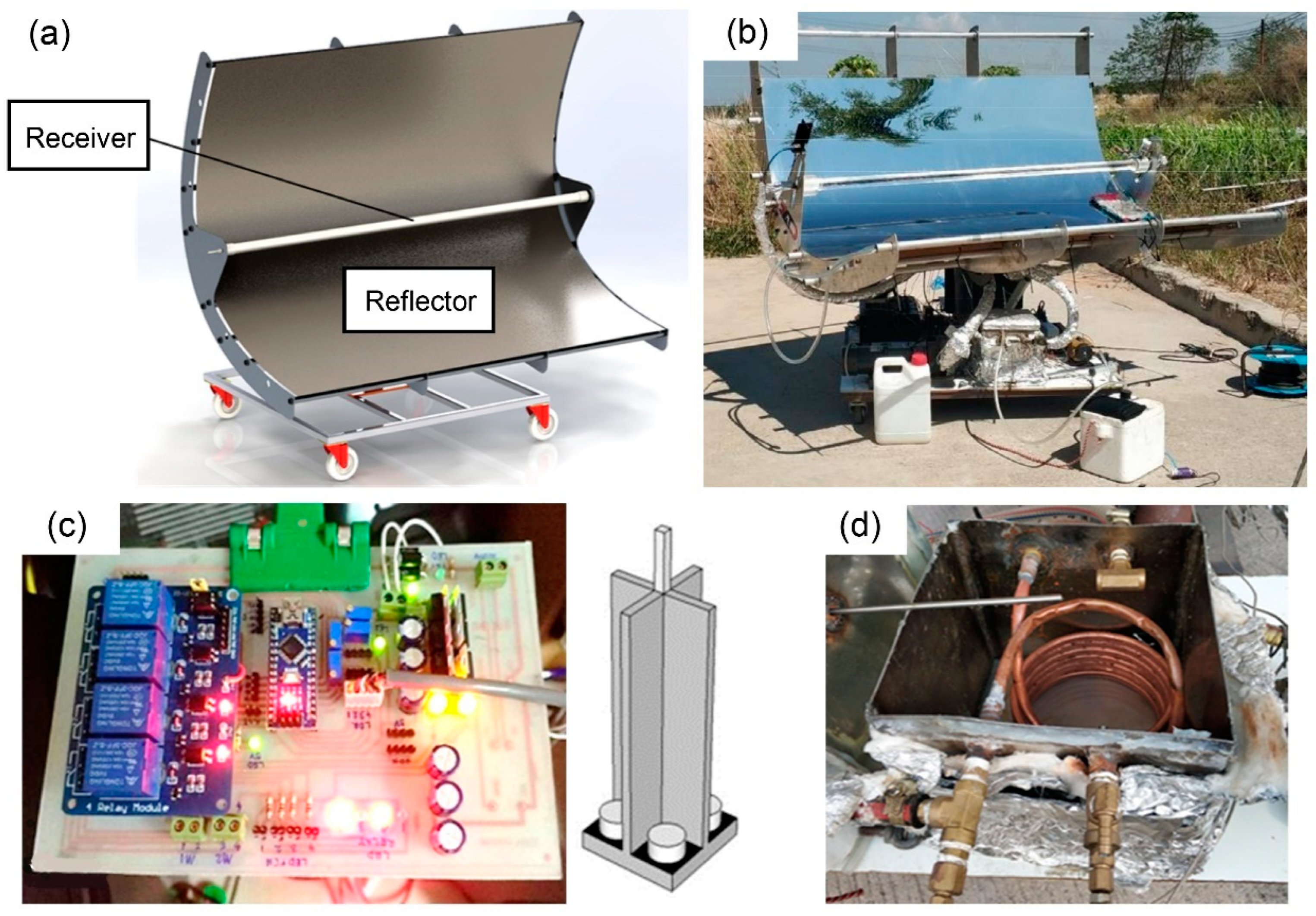
For the reasons mentioned, the name of the developed ethanol distiller is a vacuum-tube parabolic solar collector (VPSC), which is used for semi-automatic controlled ethanol distillation. The VPSC was designed using SolidWorks software, as shown in Figure 1a. The machine was assembled as shown in Figure 1b. It consists of three main parts: the solar parabolic reflector with a vacuum-tube receiver, the electronic circuit control system with solar tracking controller module and LDR sensor, as shown in Figure 1c, and the ethanol distillation system in the heat exchanger unit and condenser unit, as shown in Figure 1d.

Figure 1.
Various view of vacuum-tube parabolic solar collector: (a) perspective view from using SolidWorks, (b) photographic view after setup, (c) solar tracking controller module, and (d) heat exchanger.
The parabolic solar reflector was made of a polished stainless-steel plate with a thickness 0.5 mm and dimension (width × length) of about 1.60 m × 1.60 m. It was responsible for reflecting the solar radiation to the tube receiver. The components of the vacuum-tube receiver include a copper tube, a glass cover, and an aluminum hub. The copper tube was covered by a vacuum chamber within the glass cover. The copper tube had a thickness of 1 mm, diameter of 12.7 mm, and length of 1.8 m. The glass cover had a thickness of 5 mm, diameter of 50 mm, and length of 1.5 m. The vacuum-tube receiver was responsible for receiving the solar radiation from the reflector and transferring the heat to the working substance, such as vegetable oil.
The second part of the VPSC was the electronic circuit control system with the solar tracking controller module and light-dependent resistor sensor. This part was used to control both of the motors of the solar tracking system by receiving resistance value from an LDR sensor that can change resistance when the solar radiation is reflecting off the sensor. Because of this advantage, the resistance values could be compared and a signal was sent to the motor for adjusting the position of the reflector to be perpendicular to the solar radiation at all times.
The last part of the VPSC design was the ethanol distillation system, which comprised two components: the heat exchanger unit and the condenser unit [32,33]. The heat exchanger unit was made of a stainless-steel box and ceramic insulation with a thickness of 10 mm and dimension (width × length × height) of 0.300 m × 0.315 m × 0.250 m. The ceramic insulation prevented heat loss in the heat exchange process. The heat exchanger unit was responsible for exchanging the heat from the working substance, such as vegetable oil, in the copper tube to the ethanol concentration solution in a stainless-steel box. The condenser unit was made of an Erlenmeyer flask in which ethanol vapor was circulated, and it was immersed in cold water. It was responsible for condensing the ethanol vapor to form ethanol liquid. For the condensation process, the temperature was controlled at approximately 275–277 K by using ice as a coolant.
The equation for designing the vacuum-tube parabolic solar collector for semi-automatic controlled ethanol distillation gave the appropriate focal length of the VPSC, which was calculated from Equation (1) [34,35] as shown
f = H/2 {sec(ϕ/2) tan(ϕ/2) + ln [sec(ϕ/2) + tan(ϕ/2)]},
The length of the solar radiation receiver with the half spherical was calculated by Equation (2) [34,35].
L = Wa/tan (ϕ/2),
The radius of curvature on a parabolic reflector was calculated from Equation (3) [34,35].
r = 2f/1 + cosϕ,
For a perfectly shaped parabolic reflector, it is possible to calculate the size of the solar radiation receiver that accepts all of the images. The diameter of the cylindrical radiation receiver is calculated from Equation (4) [34,35].
where f is the focal length of parabola (m), H is the height of the parabola (m), ϕ is the rim angle (degree), L is the length of the parabola (m), Wa is the width of the solar parabolic (m), r is the radius of curvature (m), D is diameter of the solar receiver (m), and θ is the angle of incidence on the collector surface (degree).
D = 2r sin θ,
3. Experimental Setup and Methodology
The VPSC was tested on the deck of a building in Bangkok during a typical rainy season. Bangkok is located in Thailand (latitude of 13°44′ N, the longitude of 100°31′ E). The climate of the city is tropical with three distinct seasons. The summer season runs from March through to June, with April and May being the hottest months of the year. The rainy season runs from July through to October, and Bangkok’s weather is influenced by two monsoons: the northeast monsoon and the southeast monsoon. Finally, the winter season runs from November through to February. Moreover, the average daily total radiation per year of the country was 425 W/m2 [36,37].
3.1. Solution Concentration
There were two types of raw material used in this experiment: an ethanol–water mixture and a Sato–water mixture. The physical properties of the water, ethanol, and Sato are shown in Table 1 [38,39,40].

Table 1.
Physical properties of the raw material.
The ethanol solution used for the ethanol distillation was prepared in different concentrations. However, the initial volume of the solution was constant at 5 L in all of the experiments. The initial concentrations of the ethanol–water mixture were varied at 10% V/V, 15% V/V, and 20% V/V, which were calculated from Equation (5) and measured using a hand refractometer for wine and grapes. It was found that Sato had an initial ethanol concentration of 23%. Moreover, mixing the solution required a preliminary calculation of the ethanol and water content for easy mixing, as shown in Equation (5). From the calculations, the volume of ethanol was 0.5 L, 0.75 L, and 1.0 L at an initial ethanol concentration of 10%, 15%, and 20%, respectively.
V/V (%) = volume of ethanol/total volume solution
3.2. Experimental Procedure
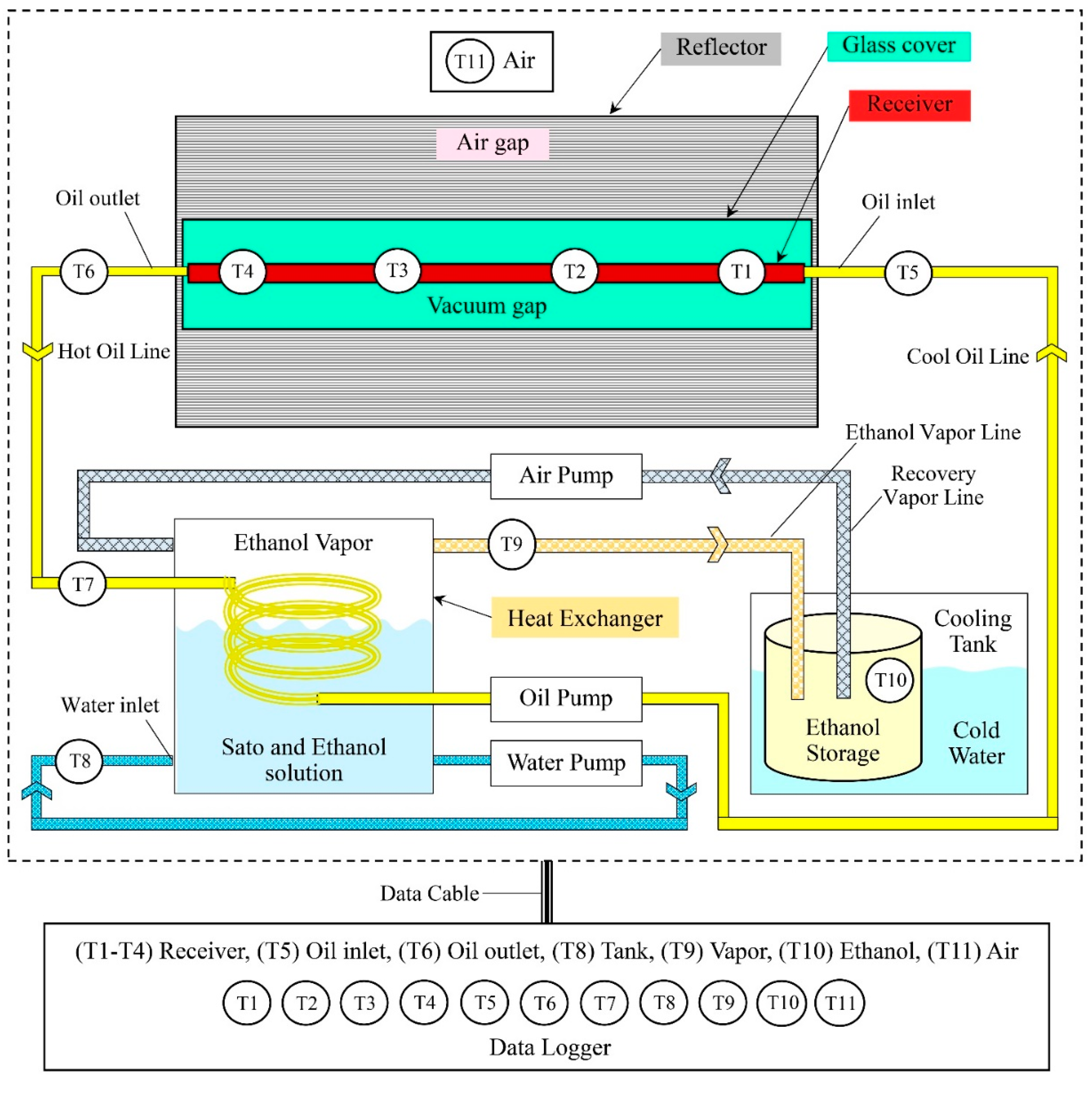
The working principle of the semi-automatic ethanol distiller with the VPSC is shown in Figure 2. The procedure started with cleaning the equipment to remove any dust. Then, the VPSC was placed under solar radiation to reflect it with the solar reflector to the vacuum-tube receiver, which was responsible for heat accumulation, by using the vegetable oil as a working substance at a temperature in the range of 383–393 K. After that, the vegetable oil flowed to the heat exchanger with a reduced temperature of approximately 363–373 K. When the oil had exchanged its heat, it was sucked back into the vacuum-tube receiver to be heated again for the next cycle [4,22].
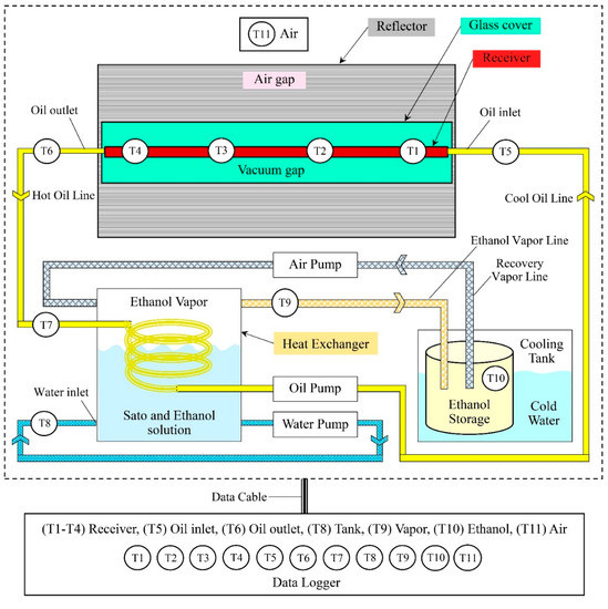
Figure 2.
Schematic diagram of the vacuum-tube parabolic solar collector system in semi-automatic controlled ethanol distillation (drawn not to scale).
In the heat exchanger unit, the vegetable oil transferred its heat to the ethanol solution. The ethanol solution was at a temperature of about 351–355 K, while the ethanol vapor, which was floating in the box, was at a temperature of about 353 K. The ethanol vapor was sucked into the condenser unit by the air pump and ice was used as a coolant in the ethanol condensation process. The remaining ethanol vapor was sucked back into the holding tank again. The distilled ethanol concentration samples obtained from the condensation process were collected in a closed system to prevent moisture from the outside air into the system.
The measurements were taken in the experiments as shown in Table 2. Experiments were performed on different days in August and October. In addition, the ambient temperature raised to its maximum value in the middle of the day, after which it tended to decline after the rise in solar radiation in the morning hours began to drop in the afternoon hours. The ambient temperature was in the range of 300–309 K. For this reason, the solar concentrator parabolic collector was warm up between 9:00 to 10:00, with the experiment starting at around 10:00 and finishing at 15:00 Bangkok local time [41]. The temperature was recorded from 10:00 onwards using the Pico model TC-08, and the global radiation was also recorded every 15 min using the Solar Power Meer CEM model DT-1307.
Table 2.
Measuring devices used in the experiments.
4. Data Collection and Calculation
The energy value for heating the ethanol solution was calculated using the energy equation of heat, which could be written as follows:
Q = mCp(ΔT),
The mass of the ethanol solution at initial ethanol concentrations of 10%, 15%, and 20% were calculated using Equation (7). From these calculations, the mass of the ethanol solution was found to be 4.894 kg, 4.841 kg, and 4.789 kg at initial ethanol concentrations of 10%, 15%, and 20%, respectively.
where ρwater is determined as about 1.0 kg/l, and ρethanol is determined as about of 0.789 kg/L.
msolution = Vwaterρwater + Vethanolρethanol,
The average specific heat of the ethanol solution at initial ethanol concentrations of 10%, 15%, and 20% were calculated using Equation (8). From the calculations, the heat capacity of the solution was 4.028 kJ/kgK, 3.947 kJ/kgK, and 3.866 kJ/kgK at initial ethanol concentrations of 10%, 15%, and 20%, respectively.
where Vsolution was determined to be 5000 mL, Cp water was determined to be 4.19 kJ/kgK, and Cp ethanol was determined to be 2.57 kJ/kgK.
Cp solutionVsolution = Cp waterVwater + Cp ethanolVethanol,
In addition, the results from the experiment were calculated in the equation; for example, the mass flow rate of the working fluid as a vegetable oil was calculated using the energy equation of heat in rate form, which could be written as follows:
where Q is measured at 168 W, Cp oil is determined to be 2.187 kJ/kgK, ΔToil is the different temperature of the oil between outlet and inlet (K), where the outlet temperature is measured at about 380.25 K, and the inlet temperature is measured at about 352 K.
Q = mCp oil(ΔToil),
The thermal efficiency of the solar collector in ethanol distillation using the vacuum-tube parabolic solar collector is shown as follows:
where Ac is the surface of the solar receiver, of about 1.76 (m2).
ηth = Q/GRAc,
5. Result and Discussion
In the semi-automatic ethanol distiller with VPSC, initial ethanol concentrations of 10%, 15%, and 20%, including the initial Sato concentration of 23%, were used for ethanol distillation. Recording of the experiment results began at 9:00 when the solar tracking system and semi-automatic control system were turned on. In this research, the solar tracking controller module is a device used to control the motors on both axes of a solar tracking system. It takes the resistance value from an LDR sensor, which can change resistance when light hits the sensor. Based on this feature, resistance values can be compared and transmitted to the motor to adjust the position of the reflector to be always perpendicular to the sunlight. In this experiment, the temperature was measured in five sections, as follows: vapor temperature, fluid temperature, cover temperature, receiver temperature, and air temperature. The measured temperature could then describe the behavior of the VPSC and were used to evaluate the condition of the distiller to increase the ethanol concentration. In addition, the global radiation was recorded to consider the relationship between the heat, global radiation, and all temperatures, including the ethanol volume related to the ethanol concentration.
5.1. Effect of Global Radiation and Temperature
Considering the experimental results of semi-automatic controlled ethanol distillation using VPSC, Figure 3 shows that the heat and the global radiation were related to the temperature at different solution concentrations. For the other temperatures in the same time in descending order, it was found that the receiver temperature had the highest temperature, followed by the oil temperature, the vapor temperature, and the fluid temperature. These findings correspond to previous research to show that the temperature difference between the oil and fluid was the driving force of the evaporation processes [38]. In addition, the vapor temperature should be close to the fluid temperature with the high-degree ethanol distillation at 84–90 °C [42].
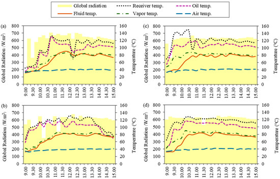
Figure 3.
Global radiation and temperature at different solution concentrations: (a) 10% initial ethanol concentration, (b) 15% initial ethanol concentration, (c) 20% initial ethanol concentration, and (d) 23% initial Sato concentration.
As can be observed in Figure 3a, the average temperatures related to the global radiation from ethanol distillation at an initial ethanol concentration of 10% showed that the fluid temperature gradually increased from 9:00 until the ethanol solution reached its highest temperature of about 356.25 K at 11:45. The average air temperature throughout the day was about 311.77 K. The results show that the global radiation had higher values in the range of 10:00–12:00 and peaked at 12:30 due to the temperature being directly related to the global radiation at the time. The maximum global radiation was approximately 703 W/m2, and the average global radiation was about 583.08 W/m2 during 9:00–15:00.
For an initial ethanol concentration of 15%, as shown in Figure 3b, it was found that the ethanol solution reached its highest temperature of about 358.5 K at 12:15. The average air temperature was about 311.86 K. The results show that the global radiation had higher values during 12:00–13:30 and peaked at 12:30 due to the temperature being directly related to the global radiation at the time. The maximum global radiation was approximately 690 W/m2, and the average global radiation was about 587.48 W/m2 during 9:00–15:00.
For an initial ethanol concentration of 20%, as shown in Figure 3c, the ethanol solution reached its highest temperature of about 356.25 K at 13:15. The average air temperature was about 312.75 K. The results show that the global radiation had higher values during 10:00–15:00 and peaked at 14:30 due to the temperature being directly related to the global radiation at the time. The maximum global radiation was approximately 648 W/m2, and the average global radiation was about 602 W/m2 during 9:00–15:00.
As can be observed, the ethanol distillation using Sato at a concentration of 23% in Figure 3d, shows that the ethanol solution reached its highest temperature of about 357.25 K at 12:15. The average air temperature was about 312.46 K. The results show that the global radiation had higher values during 10:00–15:00 and peaked at 12:30 due to the temperature being directly related to the global radiation at the time. The maximum global radiation was approximately 652 W/m2, and the average global radiation was about 612 W/m2 during 9:00–15:00.
The recorded temperatures indicate that the ethanol solution reached its highest temperatures between 11:40 and 13:15, which is related to the time of maximum global radiation. This implies that the higher solar radiation on the day of the experiment resulted in higher temperatures. As the temperature rises, the ethanol solution in the distillation chamber expands slightly, and so its specific volume increases. More heat is transferred during this process. Heat addition will cause some of the ethanol solution to vaporize. The ethanol molecules begin to move due to the increased kinetic energy. If there is continued heating, it can break the intermolecular force. Ethanol evaporates quite rapidly with respect to water due to its relatively low specific heat capacity and high vapor pressure.
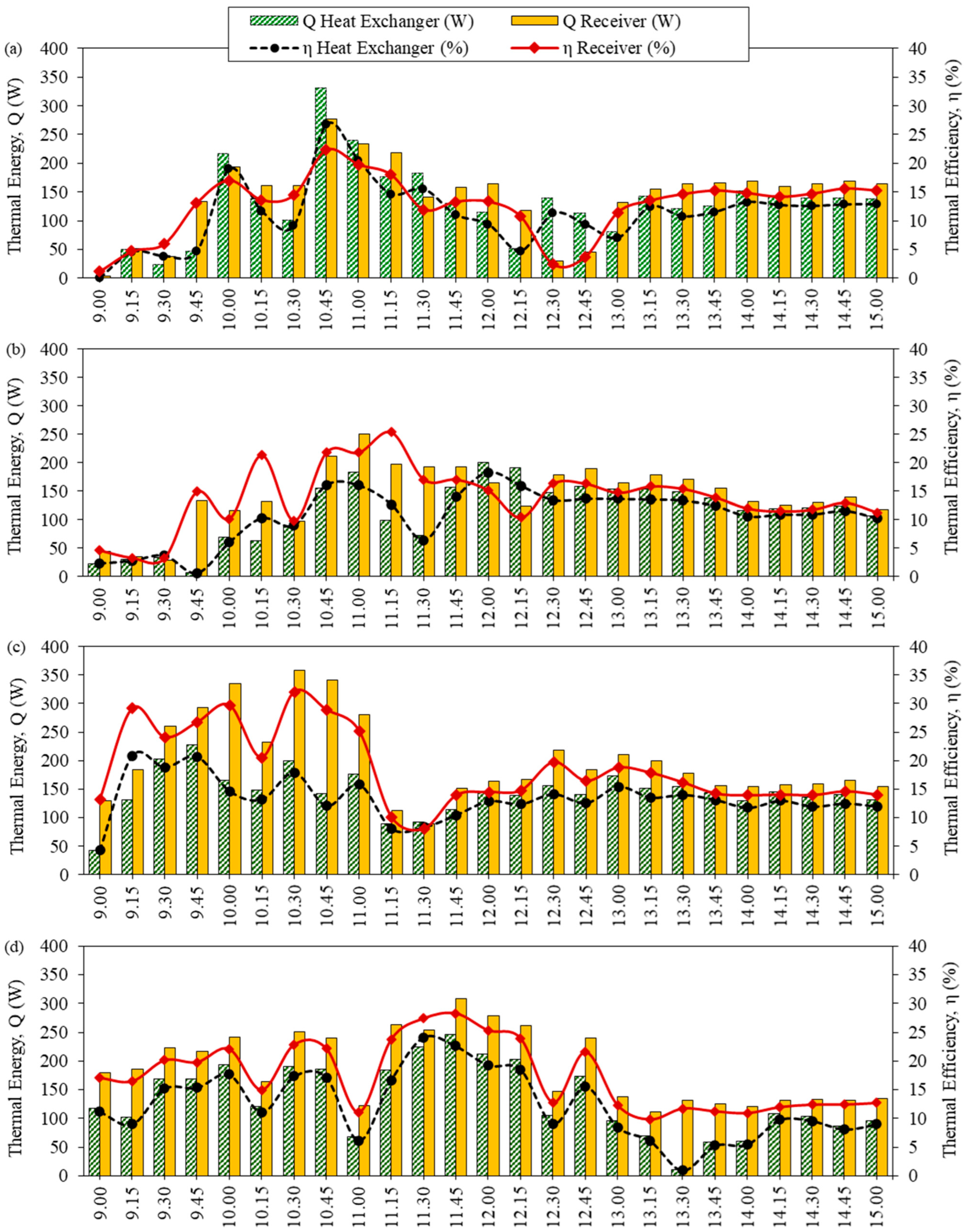
5.2. Effect of Thermal Energy and Collector Efficiency
For the semi-automatic controlled ethanol distillation using VPSC, the thermal efficiency was analyzed in two main parts: the solar receiver and the heat exchanger. Figure 4 shows the thermal energy related to thermal efficiency at different solution concentrations. The results revealed that the thermal energy and the thermal efficiency of the solar receiver were higher than the heat exchanger, as the solar receiver was responsible for receiving and accumulating heat.
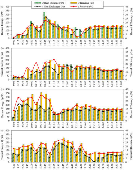
Figure 4.
The efficiency of the solar collector related to thermal energy at different solution concentrations: (a) 10% initial ethanol concentration, (b) 15% initial ethanol concentration, (c) 20% initial ethanol concentration, and (d) 23% initial Sato concentration.
Figure 4a shows the efficiency of the solar collector related to the thermal energy of ethanol distillation at an initial ethanol concentration of 10%. Comparing the heat of the system with the global radiation, the thermal energy of the solar receiver and the heat exchanger peaked at 10:45 at 331.43 W and 276.95 W, respectively. This is due to the temperature difference between the system being high in the heat exchanger.
In addition, the average thermal efficiency of the solar receiver was about 12.61%, and the average thermal efficiency of the heat exchanger was approximately 11.27%. Therefore, it is worth noting that the highest amount of distilled ethanol was the average daily solar radiation.
For an initial ethanol concentration of 15%, as shown in Figure 4b, the thermal energy of the solar receiver and the heat exchanger peaked at 249.71 W and 199.77 W, respectively, during 11:00–12:00. The average thermal efficiency of the solar receiver was about 13.93% and the average thermal efficiency of the heat exchanger was approximately 10.76%.
With ethanol, at an initial concentration of 20%, as presented in Figure 4c, the thermal energy of the solar receiver and the heat exchanger peaked at 358.68 W and 227.01 W, respectively, during 9:45–10:30. The average thermal efficiency of the solar receiver was about 18.58% and the average thermal efficiency of the heat exchanger was approximately 13.35%.
As can be observed in Figure 4d, at an initial concentration of 23% Sato, the thermal energy of the solar receiver and the heat exchanger peaked at 308.73 W and 246.68 W, respectively, at 11:45. The average thermal efficiency of the solar receiver was about 17.40% and the average thermal efficiency of the heat exchanger was approximately 12.35%.
In the event of the thermal efficiency of the solar receiver being lower than the thermal efficiency of the heat exchanger as a result of controlling the fluid temperature, the flow rate of the working fluid in the heat exchanger will be adjusted. When the oil flow rate was reduced, the oil temperature in the solar receiver was increased. As a result, the oil temperature at the inlet of the heat exchanger was increased, and heat transfer in the heat exchanger increased accordingly. However, there was a temperature control system for the heat exchanger between 84–90 °C. Therefore, when the fluid temperature reached the control temperature, the flow rate of the oil increased again. This is because the heat transfer was limited while the vapor would begin to appear at the temperature of approximately 80 °C [25]. From a comparation of the efficiency at various times, it can be observed that the difference of the receiver thermal efficiency and the difference of the heat exchanger thermal efficiency at various time were at about ±5%, because the temperature controller of fluid was set at 80 °C. As that condition, this setting directly affects the thermal efficiency.
5.3. Ethanol Volume and Ethanol Concentration
The experiment results for the ethanol volume and ethanol concentration related to time are shown in Figure 5. Recording of the experiment results started at 9:00 with the solar tracking system and the semi-automatic control system. This result shows that the ethanol was distilled at 10:45.
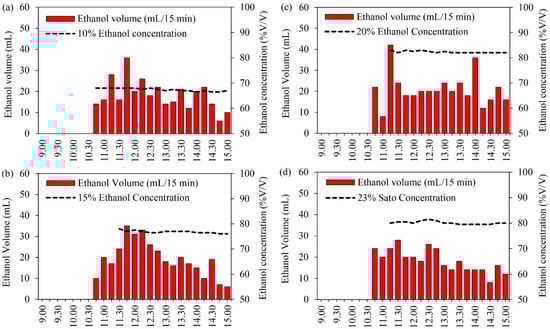
Figure 5.
Ethanol volume and ethanol concentration at different solution concentrations: (a) 10% initial ethanol concentration, (b) 15% initial ethanol concentration, (c) 20% initial ethanol concentration, and (d) 23% initial Sato concentration.
Figure 5a shows the ethanol volume and ethanol concentration at an initial ethanol concentration of 10%. It was found that the maximum distilled ethanol volume was achieved during 11:30–12:30, with the maximum global radiation and volume recorded at about 703 W/m2 and 28 mL, respectively, at 11:15. After that, the distillation volume gradually decreased from 12:30 to 15:00. The total distilled ethanol was approximately 330 mL with a maximum ethanol concentration of 68% at 11:00, after which it gradually reduced to a final ethanol concentration of 67% at 15:00.
As can be observed in Figure 5b, the ethanol volume and ethanol concentration for the initial ethanol concentration of 15% indicate that the maximum distilled ethanol volume was achieved during 11:30–12:30 when the maximum global radiation and volume were recorded at about 670 W/m2 and 35 mL, respectively, at 11:45. After that, the distillation volume gradually decreased from 12:30 to 15:00. The total distilled ethanol was approximately 352 mL with a maximum ethanol concentration of 67% at 11:30, after which it gradually reduced to the final ethanol concentration of 76% at 15:00.
At an initial ethanol concentration of 20%, the ethanol volume and ethanol concentration indicated that the maximum distilled ethanol volume was achieved during 10:30–12:30 when the maximum global radiation and volume were recorded at about 602 W/m2 and 48 mL, respectively, at 11:15, as shown in Figure 5c. After that, the distillation volume gradually decreased from 11:30 to 15:00. The total distilled ethanol was approximately 398 mL with a maximum ethanol concentration of 83% at 11:30, after which it gradually reduced to the final ethanol concentration of 82% at 15:00.
For the Sato at an initial ethanol concentration of 23%, as shown in Figure 5d, the results reveal that the maximum distilled ethanol volume was achieved during 10:30–12:30 when the maximum global radiation and volume were recorded at about 652 W/m2 and 28 mL, respectively, at 11:30. After that, the distillation volume gradually decreased from 12:30 to 15:00. The total distilled ethanol was approximately 360 mL with a maximum ethanol concentration of 81.5% at 12:30, after which it gradually reduced to a final ethanol concentration of 80% at 15:00.
In this research, ethanol concentration depends on the range of distillation temperature (84–90 °C). The experiment results indicate that the maximum distilled ethanol volume was achieved during 11:00–12:30. In the case of the initial ethanol concentration of 10%, it was found that the quantity of water in the raw material led to high water vapor in the distilled ethanol; therefore, the final ethanol concentration was low. The total distilled ethanol volume and the final ethanol concentration from the distillation process were higher at higher initial ethanol concentrations. The final ethanol concentration from Sato was similar to the initial ethanol concentration of 20%. This confirms that the VPSC can distill ethanol from agricultural products by using solar energy, and this design can distill the high ethanol concentration. Normally, it is very hard to improve the final ethanol concentration to approaching 100% in the distillation process because water vapor occurs during this process. However, if the distillation process can be designed as a standard. In particular, the process of condensing and keeping the produce free of air may also make this possible.
5.4. Specific Energy Consumption (SEC)
The specific heat energy in the ethanol distillation process was determined from the total amount of distilled ethanol per the total daily global radiation. However, the energy consumption in the solar tracking and the controller system were not considered because they had a small quantity. Initial ethanol concentrations of 10%, 15%, and 20%, and an initial Sato concentration of 23% were used in the semi-automatic control ethanol distillation using VPSC, as shown in Figure 6.

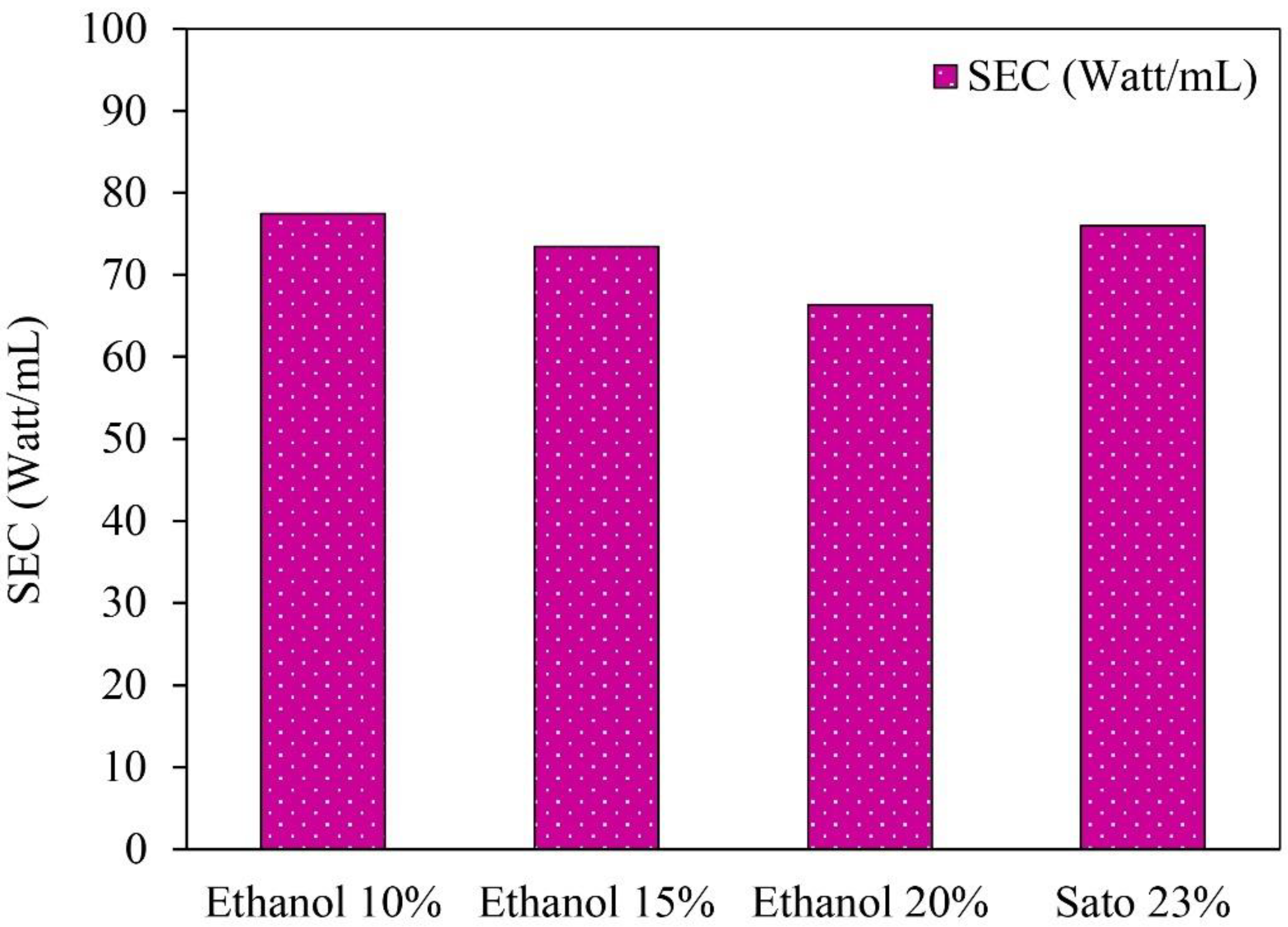
Figure 6.
Specific energy consumption (SEC) of semi-automatic controlled ethanol distillation using VPSC.
The specific energy consumption in ethanol distillation from 10%, 15%, and 20% ethanol concentrations and a 23% Sato concentration were 77.44, 72.60, 66.36, and 75.99 W/mL, respectively. The results indicate that the specific energy consumption for the Sato distillation was higher than for the ethanol distillation from the initial ethanol concentrations of 10%, 15%, and 20% due to the specific heat capacity of the Sato concentration being higher than the specific heat capacity of the ethanol concentration. The specific heat capacity of the Sato was 4.5 kJ/kgK, while the specific heat capacity of the ethanol concentrations of 10%, 15%, and 20% were 4.028, 3.947, and 3.866 kJ/kgK, respectively.
The results imply that the average energy required for 1 mL of ethanol distillation was 73.08 W/mL. This specific energy consumption could be used as reference data for the development of a solar ethanol distiller in the future. As this process is only a batch test, this design can be developed for continuous processes to increase distilled ethanol volume and reduce the specific energy consumption significantly.
5.5. Comparison of Semi-Automatic Control and Manual Control Ethanol Distillation
The semi-automatic controlled ethanol distillation using VPSC was designed and constructed to control the solution temperature by adjusting the flow rate of the oil in the heat exchanger. This is why the ethanol concentration after the distillation process in the semi-automatic controlled ethanol distiller was in the range of 60–80%, and the distilled ethanol volume was in the range of 300–400 mL. Figure 7 compares the distilled ethanol volume and ethanol concentration of the 10%, 15%, and 20% initial ethanol concentrations and the 23% initial Sato concentration between the semi-automatic controlled and manual controlled ethanol distillation process using VPSC.
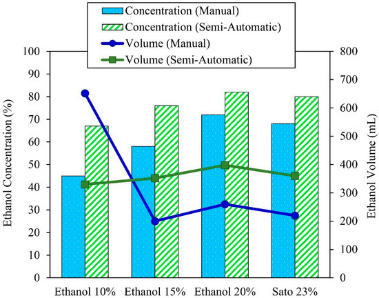
Figure 7.
Comparison of the distilled ethanol volume and ethanol concentration of the different solution concentrations between semi-automatic controlled and manual controlled ethanol distillation.
Ethanol distillation was conducted using ethanol at initial concentrations of 10%, 15%, and 20% and Sato at an initial concentration of 23%. The results indicate that the distilled ethanol concentrations increased from 45%, 58%, 72%, and 68% to 67%, 76%, 82%, and 80%, respectively. The distilled ethanol concentration differences were about 32.83%, 24.18%, 12.19%, and 15%, respectively. It was also found that the produced ethanol concentrations from the semi-automatic controlled ethanol distiller were higher than from the flat plate and parabolic solar collectors that could distill the ethanol to only 40–70%. As the semi-automatic controlled ethanol distiller can be controlled through the solution temperature by adjusting the flow rate of the oil in the heat exchanger, it can reduce the quantity of water vapor in the distilled ethanol, and thus the final ethanol concentration is increased.
Regarding the ethanol volume, the semi-automatic controlled ethanol distiller could increase the distilled ethanol volume from 200, 260, and 220 mL to 352, 398, and 360 mL through ethanol distillation from initial ethanol concentrations of 15% and 20% and the initial Sato concentration of 23%, respectively. The distilled ethanol volume differences were about 43.18%, 34.67%, and 38.89%, respectively. The ethanol volume of the 10% initial ethanol concentration after distillation with the manual controller achieved the highest ethanol volume of about 652 mL, but the distilled ethanol had the lowest concentration of about 45%. It was useless and had to be distilled again before it could be used in automotive fuel. It can be concluded that the VPSC used in semi-automatic controlled ethanol distillation could increase the ethanol concentration and volume significantly.
6. Conclusions
The vacuum-tube parabolic solar collector was used in semi-automatic controlled ethanol distillation. The distiller was developed by installing a solar tracking controller and an additional temperature controller in the distillation process. In addition, the type of solar receiver was modified to a vacuum-tube type to reduce the heat loss of the solar receiver. The VPSC was warmed up from 9:00–10:00, and then the results were recorded from 10:00–15:00, in Thailand. The initial solution had a volume of 5000 mL and used different solution concentrations of 10%, 15%, and 20% of ethanol solution and 23% Sato solution. The distillation temperature ranged from 84–90 °C.
The experiment conducted in this research studied the behavior of the distiller with regard to thermal efficiency and distilled ethanol volume with a high ethanol concentration. The effects of global radiation on temperature behavior indicate that the fluid had the highest temperature, and the vapor temperature should be similar to the fluid temperature, as the high-degree ethanol distillation begins when the solution reaches a temperature between 84–90 °C. Regarding the thermal efficiency of semi-automatic controlled ethanol distillation with 10%, 15%, and 20% initial ethanol concentrations and a 23% initial Sato concentration, it was found that the thermal efficiency of the solar receiver was 12.61%, 13.93%, 18.58%, and 17.40%, respectively. The thermal efficiency of the heat exchanger was 11.27%, 10.76%, 13.35%, and 12.35%, respectively. In addition, the final ethanol concentration obtained from the distillation process was 67%, 76%, 82%, and 80%, respectively. The distilled ethanol volumes were 330 mL, 352 mL, 398 mL, and 360 mL, respectively. In brief, the specific energy consumption used in the semi-automatic controlled ethanol distillation was 73.06 W/mL, with the average thermal efficiency of the solar receiver at about 16.2%, and the average thermal efficiency of the heat exchanger being approximately 12.52%. This implies that the most influential factor on the final ethanol concentration obtained from the distillation process was the initial concentration of the solution. Because of this research, the distillation temperature was kept in the range of 84–90 °C in order to distill the ethanol to the maximum final ethanol concentration as required. As a result, the thermal efficiency was quite low. However, the amount of heat accumulated in the system was sufficient to distill the raw material in volumes greater than 5 L.
From the experiment results, the ethanol obtained from a single distillation process had a maximum concentration of 82%. It could be used for medical sterilization, but the medical standards need to be re-examined to prevent other contaminants in ethanol. It is suggested that the ethanol could be re-distilled to a concentration higher than 95%, and it could then be used to produce gasohol and alternative fuels.
In summary, it can be concluded that semi-automatic ethanol distillation using the vacuum-tube parabolic solar collector can be used to distill ethanol. Moreover, this distiller represents a good alternative for producing ethanol in locations not served by power lines or in remote rural areas.
Author Contributions
Conceptualization, S.S.-H.P.; methodology, S.S.-H.P.; formal analysis, S.S.-H.P. and P.N.; investigation, S.S.-H.P. and P.N.; writing—original draft preparation, S.S.-H.P.; writing—review and editing, S.S.-H.P. All authors have read and agreed to the published version of the manuscript.
Funding
This research received no external funding.
Acknowledgments
The authors express their sincere to College of Industrial Technology, King Mongkut’s University of Technology North Bangkok, Thailand for supporting the facilities in this research.
Conflicts of Interest
The authors declare no conflict of interest.
Nomenclature
| Ac | surface of solar receiver (m2) |
| Cp | average specific heat of the vegetable oil (kJ/kgK) |
| Cp ethanol | average specific heat of ethanol (kJ/kgK) |
| Cp solution | average specific heat of solution (kJ/kgK) |
| Cp water | average specific heat of water (kJ/kgK) |
| D | diameter of the solar receiver (m) |
| f | focal length of parabola (m) |
| GR | global radiation (W/m2) |
| H | height of the parabola (m) |
| L | length of the parabola (m) |
| Q | the rate of energy transfer (W) |
| Qsolution | thermal energy of the ethanol distillation (kJ) |
| ρethanol | density of ethanol (kg/L) |
| ρwater | density of water (kg/L) |
| M | flow rate of the working fluid (kg/s) |
| msolution | mass of solution (kg) |
| R | radius of curvature (m) |
| V | volume |
| Vethanol | volume of ethanol |
| Vwater | volume of water |
| Vsolution | volume of solution |
| Wa | width of the solar parabolic (m) |
| ΔTsolution | difference temperature of solution (K) |
| ΔToil | different temperature of the oil between outlet and inlet (K) |
| Greek symbols | |
| ηth | thermal efficiency of the solar collector |
| θ | the angle of incidence on the collector surface (degree) |
| ϕ | the rim angle (degree) |
| Abbreviations | |
| MTBE | Methyl Tertiary Butyl Ether |
| LDR | light dependent resistor sensor |
| VSPC | vacuum-tube solar parabolic collector |
References
- Abos, H.; Ave, M.; Martínez-Ortiz, H. A case study of a procedure to optimize the renewable energy coverage in isolated systems: An astronomical center in the North of Chile. Energy Sustain. Soc. 2017, 7, 7. [Google Scholar] [CrossRef] [Green Version]
- Murachman, B.; Pranantyo, D.; Putra, E.S. Study of Gasohol as Alternative Fuel for Gasoline Substitution: Characteristics and Performances. Int. J. Renew. Energy Dev. 2014, 3, 175–183. [Google Scholar] [CrossRef] [Green Version]
- Hegde, V.N.; Hosur, V.S.; Rathod, S.K.; Harsoor, P.A.; Narayana, K.B. Design, fabrication and performance evaluation of solar dryer for banana. Energy Sustain. Soc. 2015, 5, 23. [Google Scholar] [CrossRef] [Green Version]
- Mbodji, N.; Hajji, A. Modeling, testing, and parametric analysis of a parabolic solar cooking system with heat storage for indoor cooking. Energy Sustain. Soc. 2017, 7, 32. [Google Scholar] [CrossRef] [Green Version]
- Rennkamp, B.; Haunss, S.; Wongsa, K.; Ortega, A.; Casamadrid, E. Competing coalitions: The politics of renewable energy and fossil fuels in Mexico, South Africa and Thailand. Energy Res. Soc. Sci. 2017, 34, 214–223. [Google Scholar] [CrossRef]
- Teleszewski, T.J.; Żukowski, M.; Krawczyk, D.A.; Rodero, A. Analysis of the Applicability of the Parabolic Trough Solar Thermal Power Plants in the Locations with a Temperate Climate. Energies 2021, 14, 3003. [Google Scholar] [CrossRef]
- Li, J.; Guo, H.; Meng, Q.; Wu, Y.; Ye, F.; Ma, C. Thermodynamic Analysis and Comparison of Two Small-Scale Solar Electrical Power Generation Systems. Sustainability 2020, 12, 268. [Google Scholar] [CrossRef]
- Košičan, J.; Picazo, M.Á.P.; Vilčeková, S.; Košičanová, D. Life Cycle Assessment and Economic Energy Efficiency of a Solar Thermal Installation in a Family House. Sustainability 2021, 13, 2305. [Google Scholar] [CrossRef]
- QiBin, L.; YaLong, W.; ZhiChao, G.; Jun, S.; HongGuang, J.; HePing, L. Experimental investigation on a parabolic trough solar collector for thermal power generation. Sci. China Technol. Sci. 2010, 53, 52–56. [Google Scholar] [CrossRef]
- Cleveland, C.J.; Morris, C. Dictionary of Energy, 2nd ed.; Elsevier: Amsterdam, The Netherlands, 2014; p. 700. [Google Scholar]
- Tian, Y.; Zhao, C.Y. A review of solar collectors and thermal energy storage in solar thermal applications. Appl. Energy 2013, 104, 538–553. [Google Scholar] [CrossRef] [Green Version]
- Amatayakul, W.; Berndes, G. Fuel ethanol program in Thailand: Energy, agricultural, and environmental trade-offs and prospects for CO2 abatement. Energy Sustain. Dev. 2007, XI, 51–66. [Google Scholar] [CrossRef]
- Chanthawong, A.; Dhakal, S.; Jongwanich, J. Supply and demand of biofuels in the fuel market of Thailand: Two stage least square and three least square approaches. Energy 2016, 114, 431–443. [Google Scholar] [CrossRef]
- Goedecke, M.; Therdthianwong, S.; Gheewala, S.H. Life cycle cost analysis of alternative vehicles and fuels in Thailand. Energy Policy 2007, 35, 3236–3246. [Google Scholar] [CrossRef]
- Permpool, N.; Gheewala, S.H. Environmental and energy assessment of alternative fuels for diesel in Thailand. J. Clean. Prod. 2017, 142, 1176–1182. [Google Scholar] [CrossRef]
- Verma, S.K.; Gupta, N.K.; Rakshit, D. A comprehensive analysis on advances in application of solar collectors considering design, process and working fluid parameters for solar to thermal conversion. Sol. Energy 2020, 208, 1114–1150. [Google Scholar] [CrossRef]
- Silalertruksa, T.; Gheewala, S.H. A comparative LCA of rice straw utilization for fuels and fertilizer in Thailand. Bioresour. Technol. 2013, 150, 412–419. [Google Scholar] [CrossRef]
- Eltaweel, M.; Abdel-Rehim, A.A.; Attia, A.A.A. A comparison between flat-plate and evacuated tube solar collectors in terms of energy and exergy analysis by using nanofluid. Appl. Therm. Eng. 2021, 186, 116516. [Google Scholar] [CrossRef]
- Arıkan, E.a.; Abbasoğlu, S.; Gazi, M. Experimental Performance Analysis of Flat Plate Solar Collectors Using Different Nanofluids. Sustainability 2018, 10, 1794. [Google Scholar] [CrossRef] [Green Version]
- Subramani, J.; Nagarajan, P.K.; Subramaniyan, C.; Anbuselvan, N. Performance studies on solar parabolic dish collector using conical cavity receiver for community heating applications. Mater. Today Proc. 2020, 45, 1862–1866. [Google Scholar] [CrossRef]
- Pina, E.A.; Serra, L.M.; Lozano, M.A.; Hernández, A.; Lázaro, A. Comparative Analysis and Design of a Solar-Based Parabolic Trough–ORC Cogeneration Plant for a Commercial Center. Energies 2020, 13, 4807. [Google Scholar] [CrossRef]
- Jiang, C.; Yu, L.; Yang, S.; Li, K.; Wang, J.; Lund, P.D.; Zhang, Y. A Review of the Compound Parabolic Concentrator (CPC) with a Tubular Absorber. Energies 2020, 13, 695. [Google Scholar] [CrossRef] [Green Version]
- Gilioli, A.; Cadini, F.; Abbiati, L.; Solero, G.A.G.; Fossati, M.; Manes, A.; Carnelli, L.; Lazzari, C.; Cardamone, S.; Giglio, M. Finite Element Modelling of a Parabolic Trough Collector for Concentrated Solar Power. Energies 2021, 14, 209. [Google Scholar] [CrossRef]
- Suman, S.; Khan, M.K.; Pathak, M. Performance enhancement of solar collectors—A review. Renew. Sustain. Energy Rev. 2015, 49, 192–210. [Google Scholar] [CrossRef] [Green Version]
- Soontornchainacksaenga, T.; Prakum, Y. Study on Ethanol-Water Batch Distillation. In Proceedings of the 4th TSME-ICoME, Pattaya, Thailand, 16–18 October 2013. [Google Scholar]
- Vorayos, N.; Kiatsiriroat, T.; Vorayos, N. Performance analysis of solar ethanol distillation. Renew. Energy 2006, 31, 2543–2554. [Google Scholar] [CrossRef]
- Guidi, G.; Malik, U.S.; Manes, A.; Cardamone, S.; Fossati, M.; Lazzari, C.; Volpato, C.; Giglio, M. Laser Scanner-Based 3D Digitization for the Reflective Shape Measurement of a Parabolic Trough Collector. Energies 2020, 13, 5607. [Google Scholar] [CrossRef]
- Akrami, M.; Alsari, H.; Javadi, A.A.; Dibaj, M.; Farmani, R.; Fath, H.E.S.; Salah, A.H.; Negm, A. Analysing the Material Suitability and Concentration Ratio of a Solar-Powered Parabolic trough Collector (PTC) Using Computational Fluid Dynamics. Energies 2020, 13, 5479. [Google Scholar] [CrossRef]
- Al-Falahi, A.; Alobaid, F.; Epple, B. Design and Thermo-Economic Comparisons of an Absorption Air Conditioning System Based on Parabolic Trough and Evacuated Tube Solar Collectors. Energies 2020, 13, 3198. [Google Scholar] [CrossRef]
- Yang, Y.; Boots, K.; Zhang, D. A Sustainable Ethanol Distillation System. Sustainability 2012, 4, 92–105. [Google Scholar] [CrossRef] [Green Version]
- Moosavian, S.F.; Borzuei, D.; Ahmadi, A. Energy, exergy, environmental and economic analysis of the parabolic solar collector with life cycle assessment for different climate conditions. Renew. Energy 2021, 165, 301–320. [Google Scholar] [CrossRef]
- Alsagri, A.S.; Alrobaian, A.A.; Almohaimeed, S.A. Concentrating solar collectors in absorption and adsorption cooling cycles: An overview. Energy Convers. Manag. 2020, 223, 113420. [Google Scholar] [CrossRef]
- Joshi, P.; Tiwari, G.N. Effect of cooling condensing cover on the performance of N-identical photovoltaic thermal-compound parabolic concentrator active solar still: A comparative study. Int. J. Energy Environ. Eng. 2018, 9, 473–498. [Google Scholar] [CrossRef] [Green Version]
- Macedo-Valenciaa, J.; Ramírez-Ávila, J.; Acostaa, R.; Jaramillob, O.A.; Aguilar, J.O. Design, construction and evaluation of parabolic trough collector as demonstrative prototype. In Proceedings of the ISES Solar World Congress, Cancun, Mexico, 3–7 November 2013; pp. 989–998. [Google Scholar]
- Su, Z.; Gu, S.; Vafai, K. Modeling and simulation of ray tracing for compound parabolic thermal solar collector. Int. Commun. Heat Mass Transf. 2017, 87, 169–174. [Google Scholar] [CrossRef]
- Thantong, P.; Khedari, J.; Chantawong, P. Investigation of thermal performance by applying a solar chimney with PCM towards the natural ventilation of model house under Climate of Thailand. In Proceedings of the 3rd International Conference on Applied Physics and Materials Applications (ICAPMA 2017), Chonburi, Thailand, 31 May–2 June 2017; pp. 14862–14867. [Google Scholar]
- Delina, L.L.; Ocon, J.; Esparcia, E., Jr. What makes energy systems in climate-vulnerable islands resilient? Insights from the Philippines and Thailand. Energy Res. Soc. Sci. 2020, 69, 101703. [Google Scholar] [CrossRef]
- Jorapur, R.M.; Rajvanshi, A.K. Alcohol Distillation by Solar Energy. In Proceedings of the ISES Solar World Congress Proceedings, Denver, CO, USA, 18 February 2014; pp. 772–777. [Google Scholar]
- Fallahzadeh, R.; Aref, L.; Gholamiarjenaki, N.; Nonejad, Z.; Saghi, M. Experimental investigation of the effect of using water and ethanol as working fluid on the performance of pyramid-shaped solar still integrated with heat pipe solar collector. Sol. Energy 2020, 207, 10–21. [Google Scholar] [CrossRef]
- Meng, D.; Dai, Y.; Xu, Y.; Wu, Y.; Cui, P.; Zhu, Z.; Ma, Y.; Wang, Y. Energy, economic and environmental evaluations for the separation of ethyl acetate/ethanol/water mixture via distillation and pervaporation unit. Process Saf. Environ. Prot. 2020, 140, 14–25. [Google Scholar] [CrossRef]
- Xu, R.J.; Zhang, X.H.; Wang, R.X.; Xu, S.H.; Wang, H.S. Experimental investigation of a solar collector integrated with a pulsating heat pipe and a compound parabolic concentrator. Energy Convers. Manag. 2017, 148, 68–77. [Google Scholar] [CrossRef]
- Akhter, J.; Gilani, S.I.; Al-Kayiem, H.H.; Ali, M. Optical Performance Analysis of Single Flow Through and Concentric Tube Receiver Coupled with a Modified CPC Collector under Different Configurations. Energies 2019, 12, 4147. [Google Scholar] [CrossRef] [Green Version]


Publisher’s Note: MDPI stays neutral with regard to jurisdictional claims in published maps and institutional affiliations. |
© 2022 by the authors. Licensee MDPI, Basel, Switzerland. This article is an open access article distributed under the terms and conditions of the Creative Commons Attribution (CC BY) license (https://creativecommons.org/licenses/by/4.0/).