Article

Multi-Objective Optimization Design of a Stator Coreless Multidisc Axial Flux Permanent Magnet Motor

Department of Electrical Engineering, Harbin Institute of Technology, Harbin 150080, China
*
Author to whom correspondence should be addressed.
Energies 2022, 15(13), 4810; https://doi.org/10.3390/en15134810
Submission received: 2 June 2022 / Revised: 23 June 2022 / Accepted: 28 June 2022 / Published: 30 June 2022

Abstract

:
The stator coreless axial flux permanent magnet (AFPM) motor with a compact structure, low torque ripple, and high efficiency is particularly suitable as a motor for electric propulsion systems. However, it still requires great effort to design an AFPM motor with higher torque density and lower torque ripple. In this paper, a stator coreless multidisc AFPM (SCM-AFPM) motor with a three-rotor and two-stator topology is proposed. To reduce rotor mass and increase torque density, the proposed SCM-AFPM motor adopts the hybrid permanent magnets (PMs) array with Halbach PMs in the two-terminal rotor and the conventional PMs array in the middle rotor. In addition, a multi-objective optimization model combining response surface method (RSM) and genetic algorithm (GA) is proposed and applied to the proposed SCM-AFPM motor. With the help of the three-dimensional finite-element analysis (3-D FEA), it is found that the torque ripple of the optimized SCM-AFPM motor is 4.73%, while it is 6.21% for the initial motor. Its torque ripple is reduced by 23.8%. Therefore, the proposed multi-objective optimization design method can quickly and reliably obtain the optimal design of the SCM-AFPM motor.

1. Introduction

Permanent magnet synchronous motors (PMSM), with the advantages of high efficiency, torque/power density, and power factor, are widely applied in electric propulsion systems [1,2,3,4]. In the design and control of the electric propulsion system motors, advanced drive qualities such as high torque density, low torque ripple, and high reliability are often required to meet their complex operating conditions. Therefore, how to meet such critical design requirements has become a prominent issue in the research field of electric propulsion systems.
In recent years, AFPM motors have become an attractive candidate for electric propulsion systems due to their compact structure and high power density. The use of ferromagnetic cores in the stator can reduce the permanent magnets (PMs) consumption and lower the motor fabrication cost. Therefore, AFPM motors with the stator and rotor ferromagnetic core topologies are widely accepted in electric propulsion systems for electric vehicles, electric aircraft, and electric ships [5,6,7,8,9,10]. However, the ferromagnetic cores in the stator can result in the associated eddy current and hysteresis core losses that reduce the efficiency of the motor. For AFPM motors with tooth slots in the stator, the electromagnetic vibration caused by the tooth slots is the main source of motor vibration [11]. In addition, it can also lead to large axial electromagnetic forces between the stator and rotor, which cause difficulties in the structural design and assembly of the motor [12,13].
Due to the elimination of the ferromagnetic core of the stator, the efficiency and overload capacity of the stator coreless AFPM (SC-AFPM) motors can be greatly improved, and the electromagnetic vibration is dramatically reduced [14,15]. The SC-AFPM motors are increasingly serving as drive motors for electric propulsion systems. However, compared to AFPM machines with the stator and rotor ferromagnetic core topologies, the SC-AFPM motors cause the disadvantages of low magnetic flux density and low power or torque density. In [16], the torque density of an ironless stator AFPM motor was improved by increasing the rated current density and increasing the rated speed of the motor. It can increase copper loss and reduce the endurance of the electric propulsion system. It also requires a high-strength rotor structure, resulting in heavier rotor mass and increased manufacturing costs. To solve these problems, a stator coreless multidisc AFPM (SCM-AFPM) motor with a three-rotor and two-stator topology is proposed in this paper. It improves the power or torque density in two ways: lightening the stator mass by adopting a multi-disk structure and the hybrid PMs array with Halbach PMs for the end rotors and conventional PMs for the middle rotor, and enhancing the air-gap magnetic density by forming a series magnetic circuit with PMs on different rotors.
The FEM is the best way to design these motors and find the best solutions. In [17], Halbach PMs are directly optimized by the finite element method (FEM). Due to the complex three-dimensional magnetic circuit structure of the AFPM motor, it requires a very long time to complete an electromagnetic simulation. It is very difficult to directly utilize the FEM for multi-objective optimization design. In order to reduce the calculation time of the objective function, a non-linear regression model based on a support vector machine (SVM) is proposed [18]. However, improving the efficiency and accuracy of parameter optimization requires a huge effort to establish the relationship between the input and output of the SVM model. The multi-objective optimal design method based on the response surface method (RSM) only requires a limited amount of sample data to obtain a more accurate model, which greatly improves the optimization efficiency [19,20]. In the type of the proposed SCM-AFPM motor, a notable feature is that its PMs arrangement is no longer limited to one single type, and there are two types of PMs arrangement employed in the rotor. Due to the different arrangement of the magnets in the two PM types, the magnetic circuit structure is more complex, and the coupling effect between the two PM types is more serious, so the traditional design and optimization method of the AFPM motor can no longer be used directly for the proposed SCM-AFPM motor. Therefore, how to obtain the equations of structural parameters and electromagnetic performance of AFPM motors comprehensively and effectively during the optimization design process has been a popular and challenging issue. To solve this optimization design problem of the SCM-AFPM motor, a multi-objective optimal design method based on the response surface method (RSM) and the multi-objective genetic algorithm is proposed.
In this paper, we propose an SCM-AFPM motor. In Section 2, the structure of the proposed SCM-AFPM motor is introduced, and the multi-objective optimization method for SCM-AFPM motors is presented. In Section 3, the equation of electromagnetic torque and electromagnetic power of the SCM-AFPM motor is derived. The relationship between the main dimensional parameters of the SCM-AFPM motor and its electromagnetic performances is given. Finally, an initial dimension of the SCM-AFPM motor is designed based on the conventional design method. In Section 4, a multi-objective optimization model of the SCM-AFPM motor considering torque density and thrust fluctuation is proposed. By establishing the initial motor model, determining the optimization variables and their ranges, formulating the fitness function and constraints, and performing multi-objective optimization, an optimized SCM-AFPM motor model is determined. In Section 5, the basic characteristics of the SCM-AFPM motor are analyzed. Finally, the concluding remarks are presented in Section 6.

2. Structure and Multi-Objective Optimization Approach

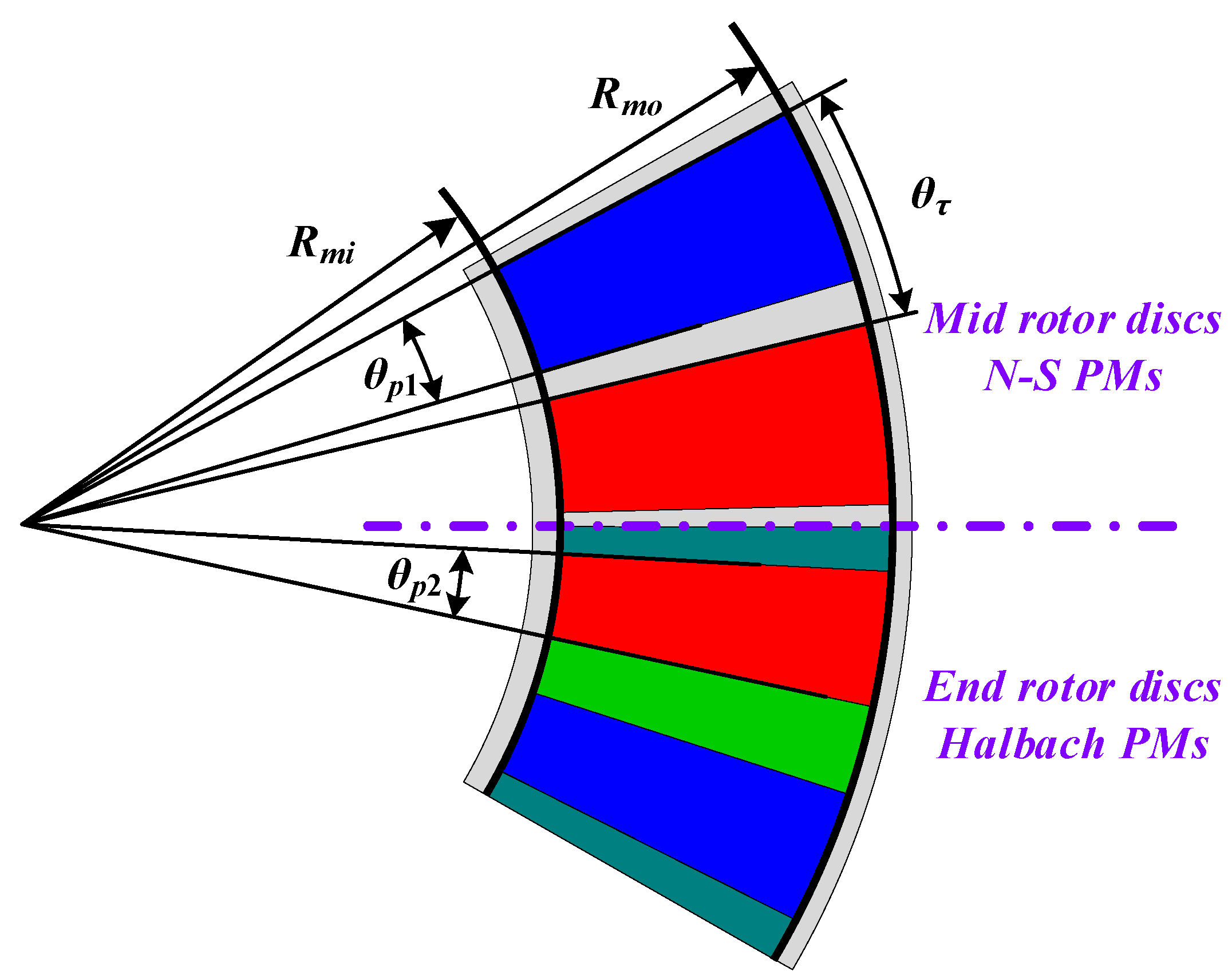
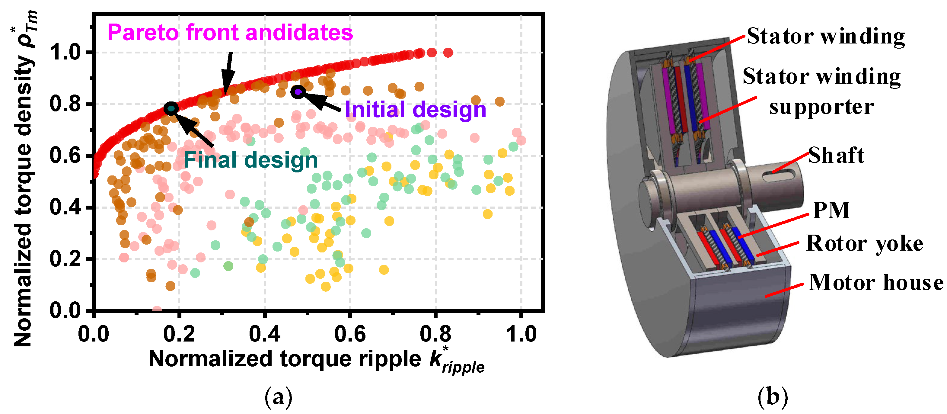
2.1. Structure of the SCM-AFPM Motor

The mechanical construction of the proposed SCM-AFPM motor is shown in Figure 1. It has a tri-rotor and dual-stator structure. The three rotors are installed on the same shaft, which rotates at the same speed in the same direction of rotation. Since the PMs on the three rotors form a series magnetic circuit, its air gap magnetic density can be improved, and the output power is larger under the same conditions. This structure can also reduce the mass of the motor rotor, thereby improving the output power density of the motor.
In addition, due to the increased non-magnetic air gap, this machine uses more PM material than an equivalent machine with a ferromagnetic stator core. In order to avoid saturation, the end rotor yoke is generally designed to be very thick, which is detrimental to the high power density of the motor. The Halbach PMs can increase the magnetic field on one side of the magnet and weaken the magnetic field on the other side of the magnet. The influence of the rotor yoke on the air gap magnetic field can be ignored for the motors with Halbach PMs. To lighten the rotor and save costs, the rotors at the terminal end are Halbach-array PMs, while the PMs of the middle rotor still adopt the N-S arrangement. The Halbach-array PM rotor is composed of four PMs per pole pair, and the magnetization direction of these four PMs varies 90° in turn. The middle rotor disk adopts a double-sided surface-mounted structure.
The two stators are composed of winding coils and winding supports. In the design of ironless stator support structures, the high-strength, non-conductive, non-magnetic materials are important to prevent stator windings from being damaged and to minimize additional losses. Therefore, epoxy resin or carbon fiber materials are chosen for the stator support structure. The main feature of the stator winding structure is the non-overlapping structure of the axial double winding, which makes coil fabrication and stator assembly easier. Due to the shorter end turn length of the non-overlapping winding, it has a shorter average number of turns in the coil, which means lower losses and lighter weight in the motor stator winding.

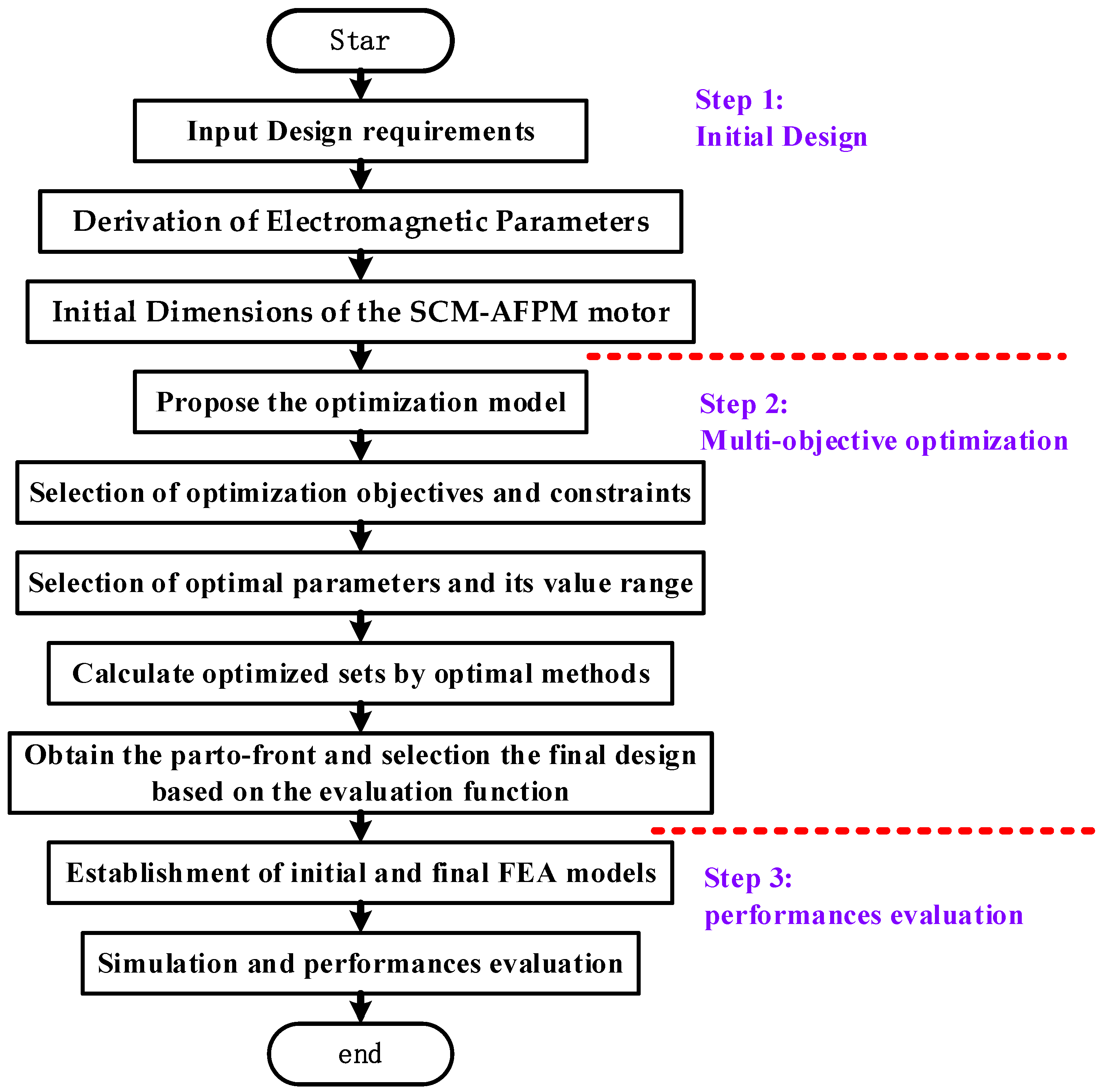
2.2. Multi-Objective Optimization Approach of the SCM-AFPM Motor

The detailed multi-objective optimization flowchart is described in Figure 2, which contains the following three steps.
Step1: 
Initial design of the SCM-AFPM motor.
In this section, there are two main steps. First, based on the electromagnetic equations of the SCM-AFPM motor, the calculation equations of its electromagnetic performance parameters such as electromagnetic torque and electromagnetic power are obtained to provide a reference for carrying out the initial design. Second, according to the design theory of the conventional AFPM motors and the proposed design requirements, the initial sizes of the initial SCM-AFPM motor can be derived.
Step2: 
Multi-objective optimization of the SCM-AFPM motor.
This part mainly includes the establishment of a multi-objective optimization model, the setting of optimization tools, and the selection of optimization results. Based on the special design requirements, the optimization objectives of the output torque density and torque ripple firstly are selected, and the optimal design parameter variables and their range are also selected. Meanwhile, the corresponding constraints are determined simultaneously. After determining the objective function, optimization parameters, and constraints of the optimization model, the improved non-dominated sorting genetic algorithm (NAGA II) is adopted as the algorithm of the optimization tool to realize the multi-objective optimization. Finally, optimized by algorithm, the parto-front of the SCM-AFPM motor can be obtained as the candidate design for the final design. Based on the design requirements, the final design individual is selected, and the final values of the design parameters can be determined.
Step3: 
Performances evaluation.
In this step, FEA simulation models are established based on the initial design sizes and the final design parameters and the simulation is carried out to verify the electromagnetic performances of the two motors.

3. Initial Design of the SCM-AFPM Motor

3.1. Electromagnetic Torque of the SCM-AFPM Motor

Figure 3 shows the layout and dimensions of a concentrated non-overlapping coreless stator winding for the SCM-AFPM motor. The equations for the electromagnetic torque and electromagnetic power of a three-phase SCM-AFPM machine with a centralized coil stator winding are derived. Note that in this analysis, only the fundamental components of the air-gap flux density and current are considered for the convenience of the calculations.
Assuming a sinusoidal axial flux density in the air gap, the flux linkage for a turn-element of radial length dr with a coil pitch π, at radius r can be determined by
λ = θ 0 π + θ 0 Δ θ c B p s i n ( θ ) r p d θ d r  
where Bp is the peak of the air gap magnetic density and p is the number of pole pairs.
Integrating the integral of (1) with θ0 = ωt, the elemental fluxes are as follows
λ = 2 p B p r d r   c o s ( Δ θ c ) c o s ( ω t )  
According to Faraday’s law, the element voltage for the N-turns coil can be determined by the following equation
e e l = 2 p ω B p r d r N k p s i n ( ω t )  
with kp given by
k p = 2 s i n ( p ( θ c Δ θ c ) / 2 ) s i n ( θ c / 2 ) θ c
From (3), the coil voltage can be determined in a simple way in which the active length of the winding is divided into ns segments, with the length of each piece dri = lc/ns at its average radius ri, as shown below:
e c o i l = 2 p ω B p N k p s i n ( ω t ) i = 1 n s l c r i k p i n s  
However, it has been found that each segment of the coil is replaced by the coil at the average radius ra of its active length; Equation (6) can also be highly accurate. The peak value of the sinusoidal phase voltage, Ep, therefore, can be written from (6) as
E p = 2 m s q ω B p r a N k p k d l c p a  
where a is the number of parallel circuits, q is the number of stator coils per phase in a stator disk, ms is the number of stator modules, and kd is a distribution factor that takes into account the effect on the induced phase voltage when the coils np in a phase group are greater than one.
k d = s i n ( n p ( p θ c π ) / 2 ) n p s i n ( ( p θ c π ) / 2 )
It is assumed that the phase current is in phase with the induced phase voltage. Therefore, the electromagnetic power of the SCM-AFPM motor can be expressed as
P m = 3 E p I p 2
where Ip is the peak of the phase current.
Therefore, the electromagnetic torque of the SCM-AFPM motor can be presented as
T m = p P m ω

3.2. Initial Dimensions of the SCM-AFPM Motor

The magnetic flux density under one pole is represented by the average magnetic density Bave, which is expressed as
B a v e = α i B p
The armature line load of the motor can be expressed as
A = 6 q N I p 2 π a D
where D is the diameter.
The design of the motor is to determine the size of the motor according to the design requirements, where the determination of its main dimensions is the basis of the motor design. If the armature line load at the average radius is considered, according to Equation (8), the relationship between the main dimensional parameters of the SCM-AFPM motor and the electromagnetic power can be obtained as
D a v 2 l c n s P m = 60 π 2 m s k p k d A B a v e
The main dimension ratio of the motor is
l c D a v = λ 1 λ + 1
with λ given by
λ = R m o R m i
where Rmo is the outer diameter of the motor and Rmi is the inner diameter of the motor.
For the design of the SCM-AFPM motor with design requirements, the corresponding dimensional design parameters can be obtained according to the traditional AFPM motor design method combined with the main motor relationship equations. The initial design size parameters of the proposed SCM-AFPM motor are shown in Table 1.

4. Multi-Objective Optimization Design of the SCM-AFPM Motor

Initial designs can be designed to meet the power requirements of the SCM-AFPM motor, but these dimensional parameters cannot meet its specific design requirements. It is still difficult and challenging to design the optimal motor size parameters and meet the multiple requirements of high torque, low torque fluctuation, and high efficiency. Therefore, a multi-objective optimization model of the SCM-AFPM motor is established, and its steps are as follows.

4.1. Multi-Objective Optimization Model

4.1.1. Optimal Parameters

The SCM-AFPM motor dimensional parameters include both stator and rotor parts, where the determination of rotor dimensions is the key step in its design. The parameters of the rotor are defined as shown in Figure 4. Five variables exist: the edge dimensions of the rotor Rmi and λ, the PMs’ magnetization length hm, the polar arc system coefficient α1 of the N-S array PMs, and the polar arc coefficient α2 of the Halbach-array PMs, which are defined as follows.
α 2 = θ p 2 θ τ
After determining the optimization parameters, the range of optimization variables can be determined by rotor space constraint, mechanical strength constraint, and initial electromagnetic analysis. The range of optimization variables is shown in Equation (16).
{ 10   mm h m 15   mm 0.75 α 1 0.9 0.4 α 2 0.6 100   mm R m i 120   mm 1.5 λ 2.2

4.1.2. Optimization Objectives and Constraints

Provided that the SCM-AFPM motor provides sufficient output power for the electric propulsion system, its size or mass should be minimized as much as possible. It not only improves the space utilization of the electric propulsion system but also can save the material consumables and reduce its manufacturing cost. Therefore, the torque density ρTm of the SCM-AFPM motor is selected as an optimization objective. The torque density ρTm is defined as follows
ρ T m = T m π ( R m o 2 R m i 2 )   h  
where   h is the total axial length of the SCM-AFPM motor.
In addition, the electromagnetic torque fluctuation of the SCM-AFPM motor is one of the main noise sources in the electric propulsion system, which affects its safe and reliable operation. Therefore, the electromagnetic torque ripple kripple of the SCM-AFPM motor is selected as the other optimization objective. The definition of torque ripple kripple can be given by
k r i p p l e T m _ m a x T m _ m i n T m _ a v g × 100 %  
The relationship between the optimization parameters and the response is given using RSM. With the central composite design method, the response values ρTm and kripple are acquired by the FEM. The ρTm and kripple are presented in Equation (19).
{ k r i p p l e = a 0 a 1 λ a 2 R m i a 3 h m a 4 α 1 a 5 α 2 + a 6 λ 2 + a 7 R m i 2 + a 8 h m 2 + a 9 R m i h m + a 10 α 1 α 2 + a 11 λ R m i + a 12 λ h m + a 13 λ α 1 + a 14 λ α 2 + a 15 α 2 2 a 16 R m i α 1 a 17 R m i α 2 + a 18 h m α 1 + a 19 h m α 2 + a 20 α 1 2 ρ T m = b 0 + b 1 λ + b 2 R m i + b 3 h m + b 4 α 1 + b 5 α 2 b 6 λ 2 b 7 R m i 2 b 8 h m 2 b 9 α 1 2 b 10 α 2 2 + b 11 λ R m i + b 12 λ h m b 13 λ α 1 b 14 λ α 2 b 15 R m i h m + b 16 R m i α 1 + b 17 R m i α 2 + b 18 h m α 1 + b 19 h m α 2 b 20 α 1 α 2
where ai and bi are constants obtained by RSM.
Many design solutions can be generated within the optimization parameters, some of which do not meet the design requirements or are unreasonable. Some constraints need to be set to exclude these ill-suited solutions. The outer diameter of the motor should be smaller than the installation size, so the outer diameter of the motor is selected as a constraint, which is expressed as follows
R m o R m o _ m a x
The optimization objectives, constraints, and design variables of the multi-objective optimization model of the SCM-AFPM motor are respectively given as follows
Optimization   Model { Objetives : { max ( ρ Tm ) min ( k ripple ) Constraint :   λ R mi < 230   mm Variables : { α 1 = [ 0.75 , 0.9 ] α 2 = [ 0.4 , 0.6 ] R mi = [ 100   mm , 120   mm ] h m = [ 10   mm , 15   mm ] λ = [ 1.5 , 2.2 ]

4.2. The Multi-Objective Optimization and Final Design

To improve the effectiveness of multi-objective optimization, the NSGA-II optimization method is utilized. Considering a trade-off between torque density and torque ripple, the evaluation function fmin is defined as
f m i n = λ   1 ρ T m * + λ   2 k r i p p l e *
where λ1 and λ2 are the weight coefficients, ρ T m * is the normalized value of torque density, and k r i p p l e * is the normalized value of torque ripple.
According to the evaluation function in (22), the final design was chosen. Figure 5 shows the optimization results of the SCM-AFPM motor and its final optimal motor topologies. The design parameters of the final design solution for the SCM-AFPM motor are shown in Table 2.

5. Performance Analysis

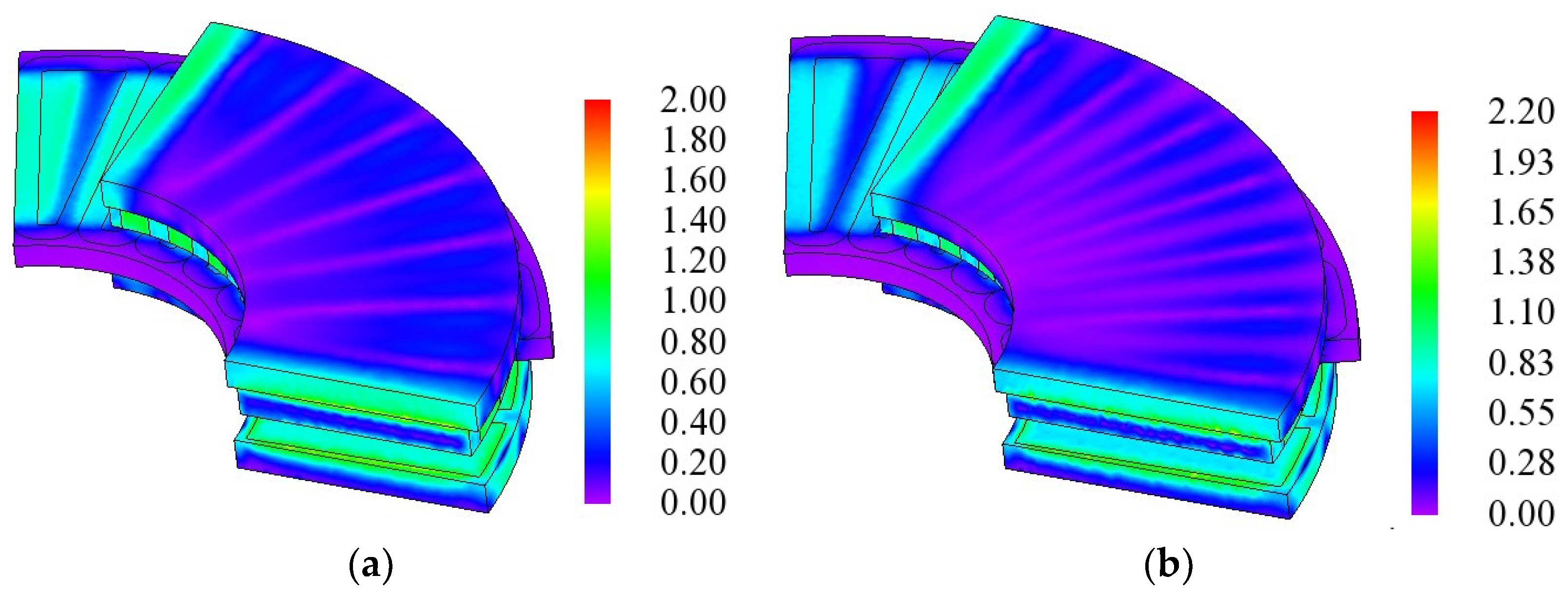
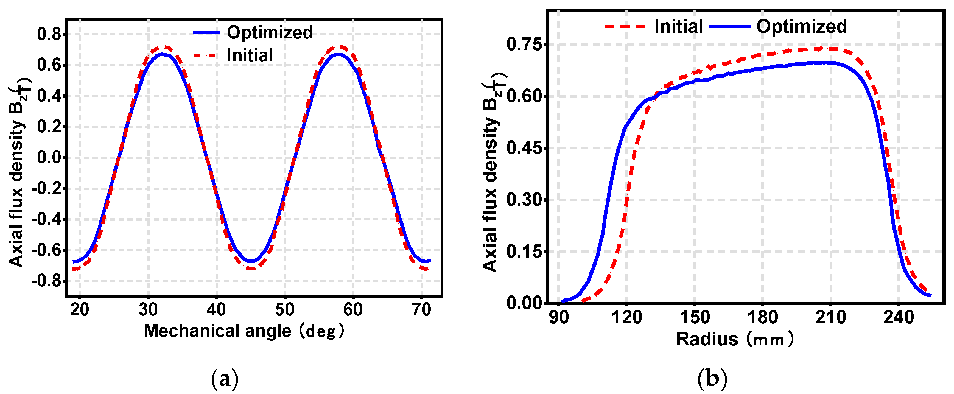
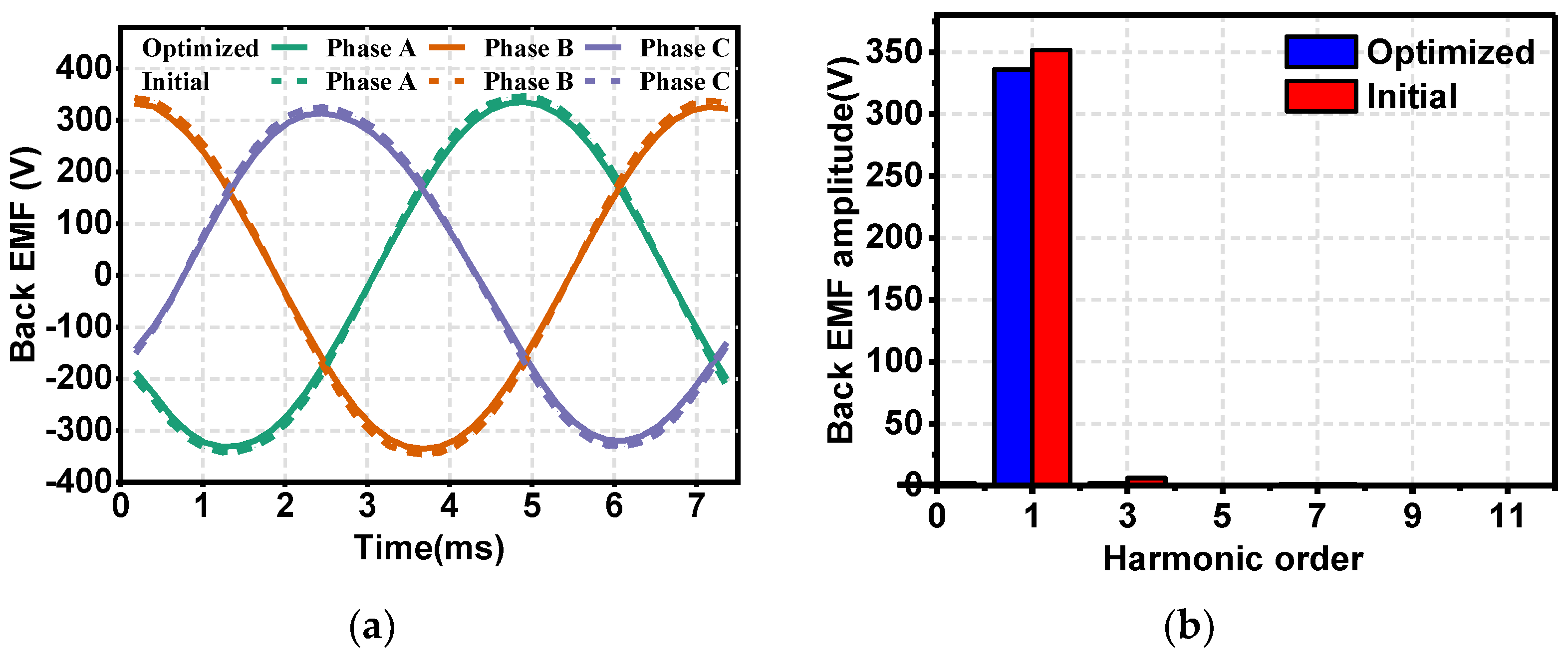
5.1. Flux Density and No-Load Back-EMF

In order to validate the utility of the multi-objective optimization method and the feasibility of the proposed optimization model, the electromagnetic performances of the optimized and initial SCM-AFPM motors are investigated in detail by FEM. For the simulations, the FEM model of the optimized and initial SCM-AFPM motors and their magnetic density cloud diagrams are shown in Figure 6, and the main simulation model parameters of the initial and optimized design are shown in Table 1 and Table 2.
The finite element simulation models of the initial and optimized SCM-AFPM motors with a rotating speed of 600 r/min were simulated, and the comparison results of the air-gap magnetic flux density are shown in Figure 7. It can be seen that the air-gap magnetic flux density of the optimized SCM-AFPM motor is slightly decreased, which is mainly due to the drop in magnetic potential caused by the thinner PMs.
The no-load back EMF of the initial and optimized SCM-AFPM motors is shown in Figure 8. It can be seen that the amplitude of the no-load back EMF of the optimized SCM-AFPM motor decreases, which is the same as the change in air-gap magnetic density, and it is also due to the fact that the optimized SCM-AFPM motor adopts thinner PMs. The no-load back EMF of the optimized SCM-AFPM motor is more sinusoidal, which contributes to reducing the SCM-AFPM motor torque variation.

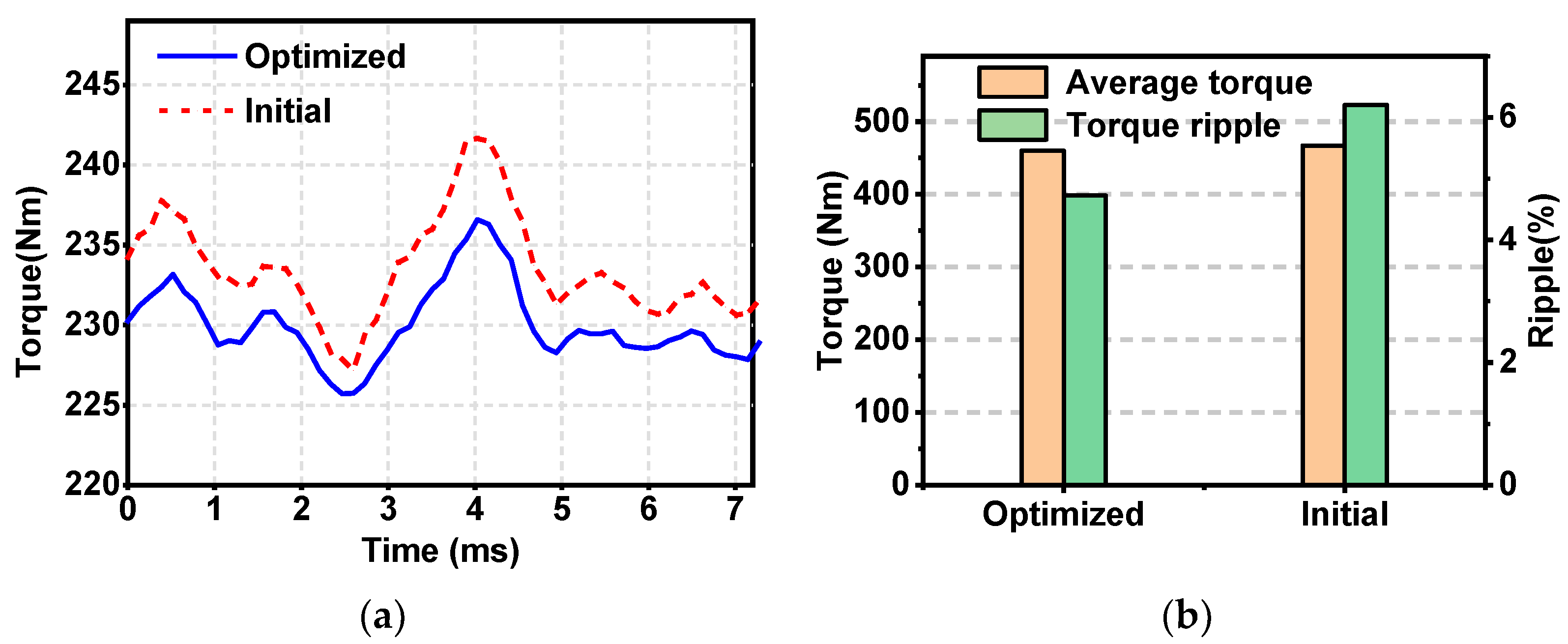
5.2. Electromagnetic Torque

Considering that the multi-objective optimization model proposed in this paper focuses on the output torque variation effect, the output performances of the initial and optimized SCM-AFPM motors were evaluated and compared under the same operating conditions. The output torque waveforms of the initial and optimized SCM-AFPM motors supplied by a three-phase sinusoidal current at 600 rpm are shown in Figure 9. As shown in the figure, the average output torque of the optimized motor is 460.03 Nm, while that of the initial motor is 467.14 Nm. In addition, the output torque ripple of the optimized SCM-AFPM motor is 4.73%, which is 23.8% lower than that of the initial motor of 6.21%. This means that, when taking torque characteristics into account during the multi-objective optimization process, the output torque ripple of the SCM-AFPM motor can be effectively reduced despite the negative impact of reduced torque density drop.

6. Conclusions

Designing AFPM motors with high power/torque density and low torque fluctuation can effectively improve the durability and economy of electric propulsion systems. In this paper, a three-rotor and dual-stator SCM-AFPM motor is proposed, which improves the torque density by adopting the hybrid PMs array to reduce the rotor mass and forming a series magnetic circuit to improve the air-gap flux density. Moreover, a multi-objective optimization design method is applied to optimize the proposed SCM-AFPM motor. With the FEM simulation, the comparison results of no-load back EMF, output torque, and torque ripple between the initial and the optimized design for the SCM-AFPM motor are presented and discussed. The research results indicate that the optimized SCM-AFPM motor torque ripple is reduced by 23.8%. Therefore, the research in this paper lays a good foundation for the multi-objective optimization design of the SCM-AFPM motor, which can serve as the drive motor for the electric propulsion system. However, the accuracy of the design depends on the accuracy of the response function. The response function accuracy can be further improved by increasing the complexity of the fitting function.

Author Contributions

Writing—original draft preparation, C.H.; data curation, C.H.; software, X.N. and X.Z.; writing—review and editing, X.Z. and L.Z.; supervision, B.K. and X.Z.; funding acquisition, B.K. All authors have read and agreed to the published version of the manuscript.

Funding

This research was funded by the General Program of the National Natural Science Foundation of China, grant number 52077042.

Institutional Review Board Statement

Not applicable.

Informed Consent Statement

Not applicable.

Data Availability Statement

The data presented in this study are available on request from the corresponding author.

Conflicts of Interest

The authors declare no conflict of interest.

References

  1. Wu, S.; Zhou, J.; Zhang, X.; Yu, J. Design and Research on High Power Density Motor of Integrated Motor Drive System for Electric Vehicles. Energies 2022, 15, 3542. [Google Scholar] [CrossRef]
  2. Xie, Y.; Xia, Y.; Li, Z.; Li, F. Analysis of Modal and Vibration Reduction of an Interior Permanent Magnet Synchronous Motor. Energies 2019, 12, 3427. [Google Scholar] [CrossRef] [Green Version]
  3. Dayo, Z.A.; Cao, Q.; Wang, Y.; Pirbhulal, S.; Sodhro, A.H. A Compact High-Gain Coplanar Waveguide-Fed Antenna for Military RADAR Applications. Int. J. Antennas Propag. 2020, 2020, 8024101. [Google Scholar] [CrossRef]
  4. Zhao, X.; Kou, B.; Zhang, L.; Zhang, H. Design and Analysis of Permanent Magnets in a Negative-Salient Permanent Magnet Synchronous Motor. IEEE Access 2020, 8, 182249–182259. [Google Scholar] [CrossRef]
  5. Aydin, M.; Gulec, M.; Demir, Y.; Akyuz, B.; Yolacan, E. Design and validation of a 24-pole coreless axial flux permanent magnet motor for a solar powered vehicle. In Proceedings of the 2016 XXII International Conference on Electrical Machines (ICEM), Lausanne, Switzerland, 4–7 September 2016; Institute of Electrical and Electronics Engineers (IEEE): New York, NY, USA, 2016; pp. 1493–1498. [Google Scholar]
  6. Taran, N.; Rallabandi, V.; Heins, G.; Ionel, D.M. A comparative study of conventional and coreless axial flux permanent magnet synchronous motors for solar cars. In Proceedings of the 2017 IEEE International Electric Machines and Drives Conference (IEMDC), Miami, FL, USA, 21–24 May 2017; Institute of Electrical and Electronics Engineers (IEEE): New York, NY, USA, 2017; pp. 1–7. [Google Scholar]
  7. Qi, H.; Ling, L.; Liwei, Z. Design and Research of Axial Flux Permanent Magnet Motor for Electric Vehicle. In Proceedings of the 2019 IEEE 3rd International Electrical and Energy Conference (CIEEC), Beijing, China, 7–9 September 2019; Institute of Electrical and Electronics Engineers (IEEE): New York, NY, USA, 2019; pp. 1918–1923. [Google Scholar]
  8. Wang, S.; Zhao, J.; Liu, T.; Hua, M. Adaptive Robust Control System for Axial Flux Permanent Magnet Synchronous Motor of Electric Medium Bus Based on Torque Optimal Distribution Method. Energies 2019, 12, 4681. [Google Scholar] [CrossRef] [Green Version]
  9. Geng, W.; Zhang, Z.; Li, Q. High Torque Density Fractional-Slot Concentrated-Winding Axial-Flux Permanent-Magnet Machine with Modular SMC Stator. IEEE Trans. Ind. Appl. 2020, 56, 3691–3699. [Google Scholar]
  10. Hajnrych, S.J.; Jakubowski, R.; Szczypior, J. Yokeless Axial Flux Surface-Mounted Permanent Magnets Machine Rotor Parameters Influence on Torque and Back-Emf. Energies 2020, 13, 3418. [Google Scholar] [CrossRef]
  11. Dini, P.; Saponara, S. Cogging Torque Reduction in Brushless Motors by a Nonlinear Control Technique. Energies 2019, 12, 2224. [Google Scholar] [CrossRef] [Green Version]
  12. Chen, Q.; Li, G.; Cao, W.; Qian, Z.; Wang, Q. Winding MMF and PM MMF Analysis of Axial-Flux Machine with Multi-Phase and Multi-Layer Winding. Energies 2021, 14, 5147. [Google Scholar] [CrossRef]
  13. Credo, A.; Tursini, M.; Villani, M.; Di Lodovico, C.; Orlando, M.; Frattari, F. Axial Flux PM In-Wheel Motor for Electric Vehicles: 3D Multiphysics Analysis. Energies 2021, 14, 2107. [Google Scholar] [CrossRef]
  14. Lawhorn, D.; Han, P.; Lewis, D.; Chulaee, Y.; Ionel, D.M. On the Design of Coreless Permanent Magnet Machines for Electric Aircraft Propulsion. In Proceedings of the 2021 IEEE Transportation Electrification Conference & Expo (ITEC), Chicago, IL, USA, 15–17 June 2021; Institute of Electrical and Electronics Engineers (IEEE): New York, NY, USA, 2021; pp. 278–283. [Google Scholar]
  15. Liu, Y.; Zhang, Z.; Wang, C.; Geng, W.; Yang, T. Design and Analysis of Oil-Immersed Cooling Stator with Nonoverlapping Concentrated Winding for High-Power Ironless Stator Axial-Flux Permanent Magnet Machines. IEEE Trans. Ind. Electron. 2021, 68, 2876–2886. [Google Scholar] [CrossRef]
  16. Zhang, Z.; Wang, C.; Geng, W. Design and Optimization of Halbach-Array PM Rotor for High-Speed Axial-Flux Permanent Magnet Machine with Ironless Stator. IEEE Trans. Ind. Electron. 2020, 67, 7269–7279. [Google Scholar] [CrossRef]
  17. Grenier, J.-M.; Pérez, R.; Picard, M.; Cros, J. Magnetic FEA Direct Optimization of High-Power Density, Halbach Array Permanent Magnet Electric Motors. Energies 2021, 14, 5939. [Google Scholar] [CrossRef]
  18. Li, H.; Cui, L.; Ma, Z.; Li, B. Multi-Objective Optimization of the Halbach Array Permanent Magnet Spherical Motor Based on Support Vector Machine. Energies 2020, 13, 5704. [Google Scholar] [CrossRef]
  19. Wang, S.-C.; Nien, Y.-C.; Huang, S.-M. Multi-Objective Optimization Design and Analysis of V-Shape Permanent Magnet Synchronous Motor. Energies 2022, 15, 3496. [Google Scholar] [CrossRef]
  20. Zhao, X.; Kou, B.; Huang, C.; Zhang, L. Optimization Design and Performance Analysis of a Reverse-Salient Permanent Magnet Synchronous Motor. Machines 2022, 10, 204. [Google Scholar] [CrossRef]
Figure 1. The basic structure of the SCM-AFPM motor.
Energies 15 04810 g001
Figure 2. Flowchart of the multi-objective optimal design.
Energies 15 04810 g002
Figure 3. Layout of concentrated non-overlapping coil stator windings for the SCM-AFPM motor.
Energies 15 04810 g003
Figure 4. Definition of the parameters in the rotor.
Energies 15 04810 g004
Figure 5. The results of multi-objective optimization for the SCM-AFPM motor. (a) the optimization results of the SCM-AFPM motor and (b) the optimal motor topologies of the SCM-AFPM motor.
Energies 15 04810 g005
Figure 6. Magnetic density cloud map of the SCM-AFPM motors. (a) the initial design of the SCM-AFPM motor and (b) the optimized design of the SCM-AFPM motor.
Energies 15 04810 g006
Figure 7. The air-gap flux density of the SCM-AFPM motors. (a) The z-directional component of the air-gap magnetic density with circumferential variation curve at the mean radius and (b) the peak value of the z-directional component of the air-gap magnetic density as a function of radius.
Energies 15 04810 g007
Figure 8. The no-load back EMF of the SCM-AFPM motors. (a) The no-load back EMF waveform and (b) the harmonic spectrum of the no-load back EMF.
Energies 15 04810 g008
Figure 9. The output torque of SCM-AFPM motors. (a) The output torque curve and (b) the comparison of the average torque and torque ripple.
Energies 15 04810 g009
Table 1. Initial design dimensional parameters of the SCM-AFPM motor.
ParametersValue
Rated speed nN (rpm)600
Number of turns per coil N12
Number of parallel circuits a2
Number of winding layers2
Number of stator modules ms2
Number of motor pole pairs p14
Number of coils per stator module Q24
The inner radius of the PMs Rmi (mm)119
Armature radius ratio λ2
Length of PMs magnetization direction hm (mm)15
Polar arc coefficient of N-S PMs α10.8
Polar arc coefficient of Halbach PMs α20.57
Air gap on one side g (mm)2
The axial length of stator module hs (mm)12
Axial thickness of a coil hcoil (mm)4
Phase number m3
Table 2. The optimized design parameters of the SCM-AFPM motor.
ParametersValue
The inner radius of the PMs Rmi (mm)110
Armature radius ratio λ2.15
Length of PMs magnetization direction hm (mm)12.5
Polar arc coefficient of N-S PMs α10.825
Polar arc coefficient of Halbach PMs α20.6
Publisher’s Note: MDPI stays neutral with regard to jurisdictional claims in published maps and institutional affiliations.

