1. Introduction
The flow separation and boundary layer control are methods aimed at improving an airfoil’s aerodynamic performance, increasing the wind turbine’s efficiency. In addition, these methods can adjust the wind turbine’s aerodynamic load and output power under varying wind speeds and ensure the generator’s safety [
1].
The design of actuators is guided by the physical principles of the phenomenon to be controlled. Thus, it is possible to delay or prevent separation by exploiting various properties of the separated or about to be separated boundary layer. The boundary layer can exist under two different flow regimes, laminar and turbulent. The fluid layers slide over each other in the laminar flow without exchanging energy and mass between the neighboring layers. Therefore, the shear developed by the velocity gradient is entirely due to viscosity. Therefore, the laminar boundary layers can withstand only very small unfavorable pressure gradients before the flow separation occurs. On the other hand, in a turbulent flow, fluctuations of the axial velocity and the perpendicular velocity to the flow direction result in a significant transfer of momentum between the neighboring layers. This allows for overcoming larger unfavorable pressure gradients due to the continuous momentum transfer in the near-wall zone [
2]. Overall, flow separation control techniques can be divided into two categories based on energy expenditure [
3]:
(1) The active flow separation control requires additional energy for the boundary layer control, such as boundary layer blowing and suction [
4,
5,
6,
7] and synthetic jets [
8,
9,
10], which can operate in two ways: (i) in an open-loop where the injection or suction of fluid is independent of the state or conditions of the flow such as wind speed and angle of attack (along the wingspan); (ii) in closed-loop, where the information is obtained from the sensors to control the rate of fluid injection/aspiration or to disable the control system in operating conditions where the flow is attached. Here we must mention that the open-loop or closed-loop methods are applicable for all active control methods [
11], plasma actuators [
12], and so on.
(2) Passive control techniques that do not require auxiliary power or a control loop, such as slot [
13], multi-element airfoil [
14,
15,
16], leading-edge slat [
1,
17], Gurney flap [
18,
19,
20], self-activated flaps [
21], vortex generator [
22,
23,
24], stall strips [
25,
26], and other airfoil configurations that can delay or even eliminate dynamic stall.
Handley Page [
27] and Lachmann [
15,
28] initially introduced the slotted and multi-element airfoils, but the first thorough and systematic study of these elements was performed by Weick and Shortal [
29]. Weick and Shortal examined various combinations of slots and various slot locations to identify the optimal aerodynamic configuration. For an un-flapped airfoil, their study shows that the most effective position for a single slot is near the leading edge. However, when the slot is moved aft, the effectiveness decreases.
Multiple slots are generally relatively ineffective unless they include a slot near the leading-edge [
29,
30]. The leading-edge slot was firstly used in aircraft to delay the boundary layer separation at a low relative speed [
16]. The particularity of this technique is to energize (adding kinetic energy) the boundary layer by augmenting the flow in the gap between the main body and slat [
31], creating either large vortices or multiple smaller vortices, leading to separation delay of the main airfoil boundary layer. The hydrokinetic and wind turbines with leading-edge airfoil-slat were numerically and experimentally investigated by Yavuz et al. [
32,
33]. Their results showed that the stall angle of attack increased by 8°, and the maximum lift coefficient increased by 191.7%.
Akhter and Omar [
10] noted a shift in the separation point from 47% to 0.67% chord for the slat configuration. They also noted that the geometric parameters and slat position relative to the blade are essential for performance enhancement. In addition, the circulation around the leading edge slat reduces the sharp increase in the flow velocity over the main airfoil body, thus regulating the flow separations and causing an improved pressure recovery [
34].
Similarly, the use of a micro-cylinder was investigated for aerodynamic performance enhancement and flow separation control. Shi et al. [
35] used an oscillating micro-cylinder at the leading edge and recorded an increase of 88.21% in lift/drag ratio at optimum oscillation mode. Furthermore, setting a micro-cylinder with a 1 mm diameter at the blade leading edge can improve torque under light stall conditions for 10 m/s free flow velocity [
36].
Luo et al. [
37] performed a parametric numerical study using Reynolds averaged Navier-Stokes calculation combined with delayed detached eddy simulation on a NACA0012 airfoil equipped with a micro-cylinder. The position of the micro-cylinder was at x/c = 0.02 based on a hypothesis that flow separation is impossible to control further downstream. They concluded that aerodynamic performances are highly sensitive to the spacing between the cylinder and suction surface.
A hybrid Reynolds averaged Navier–Stokes/Large-Eddy-Simulation turbulence technique was adopted by Liggett et al. [
38] to study an oscillating flapped airfoil to determine the influence of modeling the gap on the performance and acoustic signature of the airfoil. Their results are compared with the experimental data to confirm the validity of the computational approach. They examined both attached and separated oscillating flows. The flow physics within the gap is important for the airfoil performance when a stall occurs and when acoustic signatures are required.
Two-dimensional RANS equations are common for CFD analysis of specific studies related to airfoil flow control. For example, Ramzi and Abed Errahmane [
39] studied the effect of slot geometry on a cascade of the highly loaded axial compressor. Based on their 2-D analysis, results showed a maximum reduction of 28% of the loss ratio and an increase of 5° in the flow deflection angle.
To increase the power production of a modern multi-MW rotor [
40], a two-dimensional CFD optimization approach was adopted by Gaunaa et al. [
41], where the effects of using slots were quantified. The results indicate that the slats boost the aerodynamic performance of the inner part of rotors, and the effects may be better if the slats and the main rotor blade are designed simultaneously.
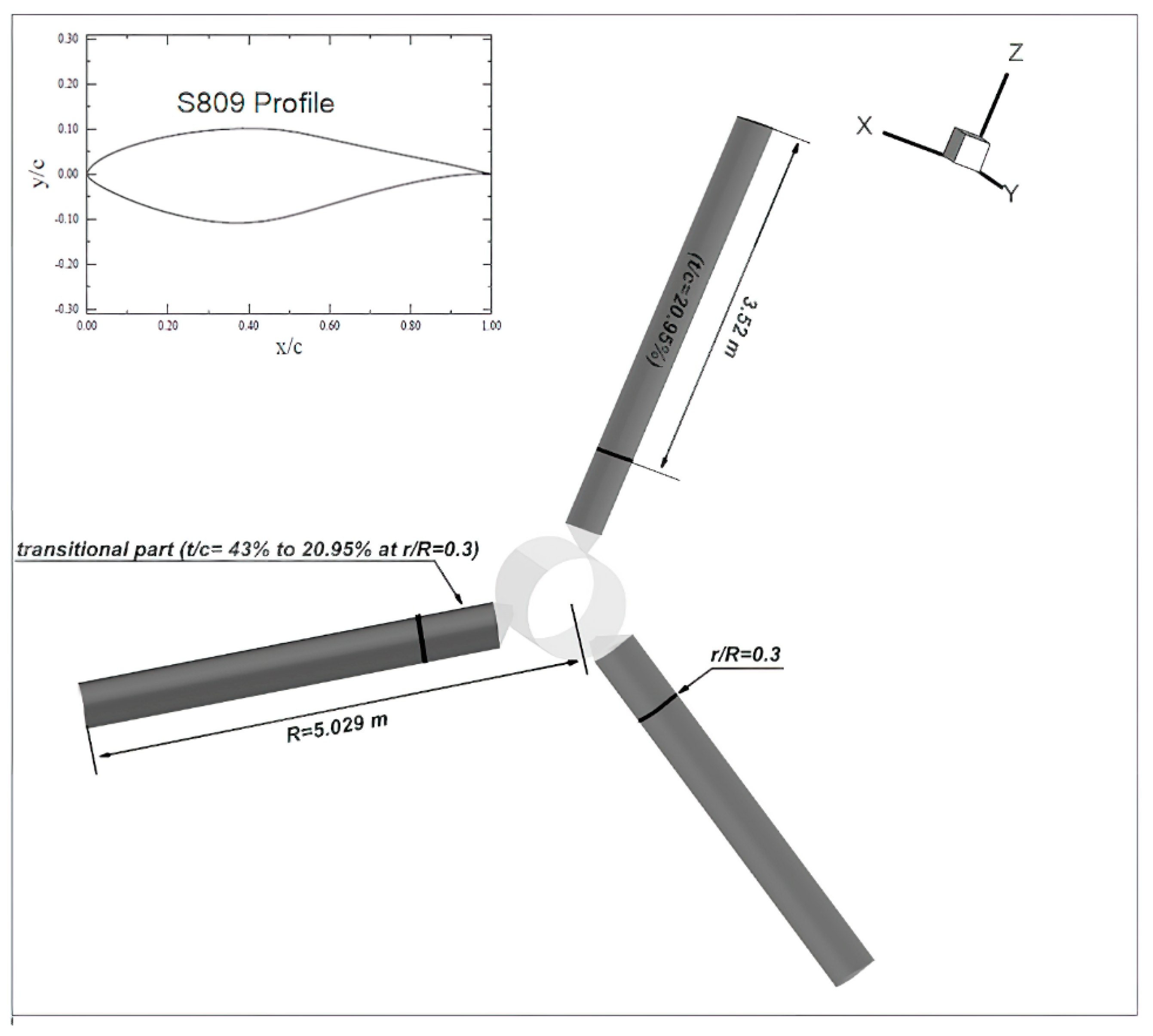
Standish [
42] performed an extensive 2-D computational study to examine the influence of tab height and tab location on the upper and lower surfaces of the S809 and GU25-5(11)8 airfoils. His results show that the optimal tab height was in the order of the boundary layer thickness. Furthermore, the optimal location was at approximately 95% of the chord in terms of lift versus drag.
Buhl et al. [
43] used 2-D calculation to investigate trailing-edge flaps of a 5 MW upwind reference turbine without changing its lift coefficient. Their analysis indicates that the potential of using trailing-edge flaps to reduce fluctuating loads is significant.
From the above works, the 2-D approach does not give a full insight into the complex 3-D flow phenomena around the wind turbine blade. For example, both rotation and radial flow components present in the rotor have a major effect on the lift and drag characteristics of the blade compared to a 2-D airfoil [
44]. In 3-D rotor flows, two main factors are generally involved: (i) the Coriolis force, which acts in the direction of the chord as a favorable pressure gradient and tends to delay the separation of the boundary layer; (ii) the centrifugal forces, which produce a pumping effect in the spanwise direction.
Using a viscous-inviscid interaction model, the 3-D equations of the boundary layer on a rotating surface are solved numerically by Sørensen [
45]. His results show a significant difference between the lift coefficients calculated for 2-D and 3-D cases.
Du and Selig [
46] approached the resolution of the 3-D equations of the incompressible stationary boundary layer. Their analysis indicated that the delay in separation depends slightly on the effect of the pressure and mainly on the acceleration of the boundary layer flow, i.e., on the Coriolis forces. The two rotation effects become smaller going outwards, according to [
47,
48].
Hu and his colleagues [
49] carried out a study on separation delay for wind turbines. The complex flow fields are simulated using CFD based on the 2-D stationery and 3-D rotation conditions. Their computation results show that rotation affects the pressure distribution on the surface, which can increase the 3-D stall-delay on Horizontal Axis Wind Turbines (HAWT).
This list is far from being exhaustive. Flow control methods, in all their forms, are widely used in the turbomachinery field, especially those with high aerodynamic loading (high-pressure ratio). For example, Cravero et al. [
50] carried out a CFD simulation to study the effect of the ported shroud on the radial compressor stage under different operating conditions. Moreover, it develops some criteria to detect the limiting mass flow rate compared to a compressor without this device. Here, at the design rotational speed, an increase of 11% of the surge margin has been detected. Gabriel et al. [
51] experimentally studied the effect of an active control to improve the stability of an axial compressor stage CME2 operating at 3200 rpm. It is an air injection system (continuous and pulsed) composed of 20 injectors that work independently of each other. Their results show that the control system improved the compressor operating range by decreasing the stalling mass flow rate and increasing the pressure rise for a given operating point.
The current work consists of a 3-D CFD modeling of a rotating blade equipped with different flow control systems: single-slot (S-S) and two-slots (T-S). The computation provides a better understanding of the influence of these flow control devices on the performance of wind turbine blades. The results are helpful for the development of a new generation of wind turbine blades. Several issues have been addressed, including the control of boundary layer separation and the rotation effect with the control system. The increase in the power output reaches over 60% at high wind speeds with large separated boundary layer regions.
4. Conclusions
The current work consists of a 3-D CFD modeling of a rotating blade equipped with different flow control systems: single-slot (S-S) and two-slots (T-S). The computation provides a better understanding of the influence of these flow control devices on the performance of wind turbine blades. The results are helpful for the development of a new generation of wind turbine blades. Several issues have been addressed, including the control of boundary layer separation and the rotation effect with the control system. The results of the calculations were entirely satisfactory, and, in our opinion, they can represent a sound basis for future work in the wind turbine field. The most significant results are summarized below.
The capacity of the CFD-RANS method for calculating aerodynamic performance and loads on wind turbine blades has been demonstrated. While the agreement with the experimental data was better for the attached flow and close to the nominal conditions, the tool is suitable for designing blades equipped with control systems. In addition, the turbulence model k-ω SST with the advanced wall modeling approach used in this work has given good results even at relatively high angles of attack.
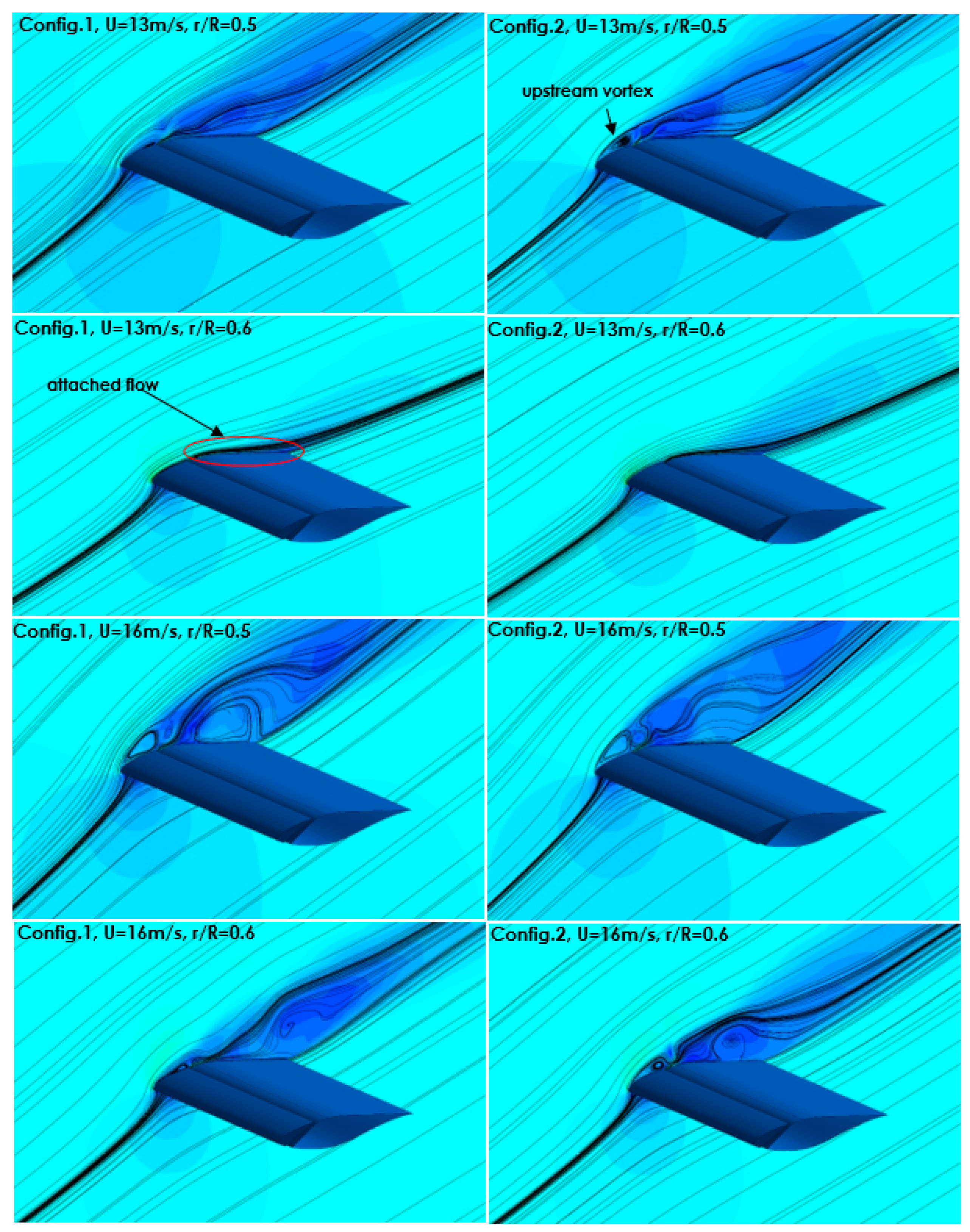
The presence of the slot has shown its ability to delay the boundary layer separation in the 3-D flow of the rotary blade. However, the improvement in aerodynamic performance has been proven only for medium and high wind speeds (), when the boundary layer is generally separated. Low wind speed (low angle of attack) makes it not effective to use slots for flow control (which is the main limitation), as the wind turbine power output is reduced. Therefore, it is necessary to design a blade with variable geometry that operates with slots only at higher wind speed, i.e., angle of attack. This can be done with a system opening or closing the slot according to wind speed. Indeed, at high angles of attack, the slot will significantly increase the overall performance of the rotor and the energy efficiency of wind turbines. The addition of a second slot near the leading edge further improves the power output and the flow behavior compared with the single slot configuration.
We noticed that the control system has no positive effect on the inboard region of the rotor due to the large separation on the entire upper surface. Therefore, we suggest applying a hybrid approach using two different control methods:
- (i)
A first method (active or passive) for the inboard region of the rotor that does not depend on the separation point of the boundary layer. In fact, in this region (up to 30 to 40% of the blade span), the separation begins from the leading edge. However, applying a control method that must be located just upstream of the separation point will not be effective in this case;
- (ii)
A second control method with two slots is applied for the middle span and the outboard region.


