Article

Numerical Analysis of Conjugated Heat Transfer and Thermal Stress Distributions in a High-Temperature Ni-Based Superalloy Turbine Rotor Blade

School of Energy Science and Engineering, Harbin Institute of Technology, Harbin 150001, China
*
Author to whom correspondence should be addressed.
Energies 2022, 15(14), 4972; https://doi.org/10.3390/en15144972
Submission received: 7 June 2022 / Revised: 28 June 2022 / Accepted: 4 July 2022 / Published: 7 July 2022

Abstract

:
This paper establishes a multidisciplinary method combining conjugate heat transfer (CHT) and thermal stress for a high-temperature Ni-based superalloy turbine rotor blade with integrated cooling structures. A conjugate calculation is performed to investigate the coolant flow characteristics, heat transfer, and thermal stress of the rotor blade under rotating and stationary conditions to understand the effects of rotation on the multidisciplinary design of the blade. Furthermore, the maximum resolved shear stress among the 30-slip systems and the corresponding dominant slip system are obtained to predict the deformation tendency of the blade by employing the crystal plasticity finite element method (CPFEM) and considering the specified anisotropic blade material (GTD-111). The results show that the forces of rotation, including centrifugal and Coriolis forces, and their induced buoyancy force, alter the coolant flow field and thus affect the rotor blade’s heat transfer distribution compared with the stationary condition. The maximum temperature and thermal stress of the rotor blade under rotating conditions are reduced by 5% and 21% compared with that under the stationary condition, respectively. Compared with the stationary condition, the temperature and thermal stress distribution on the blade under the rotating condition are more uniform, especially on the suction side. In addition, the blade root connecting with the hub, the film holes near the leading-edge region at the blade root, the mid-chord of the suction surface, and the grooved blade tip are easily damaged by the enormous resolved shear stress and the interface effect of different types of dominant slip system under the two conditions. In this work, it was feasible to use the cascade cooling effect test to analyze the dynamic test results for the rotor blade. Furthermore, the thermal stress analysis based on the CPFEM can provide a superior level of blade cooling design than CHT by considering the anisotropic material characteristics of a turbine blade.

1. Introduction

Currently, one of the primary methods of developing high-performance gas turbines is increasing turbine rotor inlet temperatures (RIT). Today, the RIT of advanced gas turbines is around 2000 K, which is considerably higher than the yielding temperature of the blade superalloy material [1]. Typically, turbine blades undergo extreme operation conditions, with high temperature, high pressure, and high flow velocity. Therefore, innovative cooling techniques and thermal barrier coatings for advanced gas turbines are extremely important for increasing turbine blade life and ensuring the safe operation of high-temperature gas turbines. In addition, the turbine-cooling flow field is affected by the centrifugal, Coriolis, and rotational buoyancy forces of a rotor blade, which thus significantly influences heat transfer. However, we did not fully understand the rotational effects on the heat transfer performance of cooling channels until the late 1980s and early 1990s [1].
In the past 30 years, numerous scholars have focused on rotational effects on flow characteristics and heat transfer performance in turbine cooling (internal cooling and film cooling) by both experiment and numerical simulation [1,2,3,4,5,6,7,8,9,10,11,12,13]. Wagner et al. [2,3] were the first to use nondimensional parameters, such as rotation number and buoyancy number, to study the rotational effects on heat transfer. Han et al. systematically investigated the rotational effects on the flow and heat transfer of turbine cooling, including the different cooling structures, arrangements, and boundary conditions [4,5,6,7,8,9,10,11,12]. They first proposed and verified the internal cooling channel orientation redesign to enhance the heat transfer of the blade’s cooling passages on the suction and pressure surface in rotation. They additionally recognized the importance of research on the coolant structures of the rotor blades, with realistic cooling channel geometry, shape, and orientation [1]. Yeranee and Rao [13] reviewed the literature describing the rotational effects on turbine internal cooling from 2010. They indicate that higher rotation, Reynolds and buoyancy numbers of the coolant channels should be investigated in the future. They also believe that experimental studies on the effect of rotation on turbine blade internal cooling structures should be emphasized in future research. Nevertheless, dynamic experiments with cooled turbine blades in realistic operation are extremely difficult. Thus, the static cascade cooling effect test is usually employed to research the cooling effect of the rotor blade to verify whether the blade meets the cooling design requirements. There are some differences between the static experimental results and the actual rotation status. For example, the coolant flow characteristic and coolant distribution of a rotor blade could not be obtained in a static test.
Moreover, turbine blade cooling generates destructive thermal stress for the blade due to the uneven distribution of wall temperature. Previous studies show that more than 42% of gas turbine damage originates from blade failure [14]. Therefore, thermal stress is also an essential parameter in turbine blade design. Kim et al. [15] studied heat transfer and stress (the combined effects of pressure, uneven temperature, and rotation) of a turbine rotor blade (3600 PRM) with 10 circular internal cooling channels by the conjugated simulation method using FVM and FEM. The results show that the maximum temperature and thermal stress were located in the trailing-edge region around the mid-span of the blade. The maximum stress on the external wall of the blade occurs on the blade root due to the limitation of the hub. The study by Ziaei-Asl and Ramezanlou [16] also showed that the cooling channel near the blade root was under enormous stress. Staroselsky et al. [17] used the coupled methodology of computational fluid dynamics (CFD) and the thermal–structural finite element model (FEM) with a slip-based constitutive model to predict the life of realistic turbine airfoils under nonhomogeneous transient temperature. Wang et al. [18] proposed a fatigue life prediction model for nickel-based single-crystal blade on the basis of the resolved shear stress amplitude. The model has excellent application prospects by using the maximum resolved shear stress of the primary octahedral slip system as the damage parameter at a lower temperature. However, the model has higher application potential when utilizing the stress amplitude as the damage parameter at a high temperature.
Yue et al. have performed much research on the crystal plasticity theory of nickel-based single-crystal superalloy and its application in cooled turbine blades [19,20,21,22,23]. They proposed a life model of a single-crystal turbine blade based on the rate-dependent crystal plasticity theory. The low-cycle fatigue life model of the blade is a power function of the maximum resolved shear stress of the activated slip system [19,20,21]. They found that the locations of maximum resolved shear stress in the blade do not correspond to the most dangerous locations due to the temperature distribution and the complexity of the cooling channels. Thus, the design of cooling blades should comprehensively consider the stress and temperature distribution [19]. Arakere et al. [24] proposed the concept of a “dominant slip system”, which corresponds to the highest value of resolved shear stress in the single slip system. Their research showed that the material anisotropy changed the number of dominant slip systems while also changing the boundaries of the dominant slip systems. Therefore, blade material anisotropy should be considered when studying the thermomechanical stress of air-cooled turbine blades. Mao et al. [25] investigated the dominant slip system around the circular hole in Ni-based single-crystal superalloys. The results show that cracks start at the interface of the dominant slip system to create deformation bands.
A variety of works have studied the simplistic internal cooling and film cooling efficiency of turbine blades under the rotation condition, and the thermal stress of the simplified blades. Fewer studies have focused on the differences in the flow field, heat transfer characteristics, and thermal stress of the practical blade under stationary and rotating conditions. This paper couples the CHT and a sequentially coupled thermal–mechanical analysis with CPFEM to study the coolant flow, heat transfer, and thermal stress of a high-temperature Ni-based superalloy turbine rotor blade under rotating and stationary conditions in practical boundary conditions. The blade’s differences in coolant flow and heat transfer are evaluated under both conditions. The blade temperature is the predefined field to calculate the thermal stress of the rotor blade. Then, the maximum resolved shear stress (MRSS) and its corresponding dominant slip system (DSS) on the blade are obtained to analyze the dangerous regions and difference of the blade under both conditions by considering the material anisotropy.

2. Numerical Method

2.1. Governing Equations of the Thermal Fluid–Solid Coupling

CHT analysis is typically used to analyze the heat transfer between the solid and fluid domains of a cooled turbine blade. At the solid–fluid interface, the energy equations are solved with equal temperature and heat flux. Convective heat transfer and heat conduction (between solids) in the turbine cascade flow are calculated simultaneously, and the influence of radiation heat transfer is not considered in this work. The computational sub-domains of CHT analysis in a cooled turbine blade consist of high-temperature mainstream gas (fluid domain), low-temperature internal coolant (fluid domain), and turbine blade (solid domain). There are four main governing equations (continuity, momentum, and energy-conservation equations for fluid domains, and the heat conduction equation for solid domains) in CHT analysis [26]. The governing equations of fluid domains are written as follows in Equations (1)–(3).
ρ t + · ( ρ U ) = 0
( ρ U ) t + · ( ρ U U ) = p + · τ + S M
ρ h tot t p t + · ρ U h tot = · ( λ T ) + · ( U · τ ) + U · S M + S E
where τ represents the stress tensor, h tot = h stat + 1 2 U 2 represents the total enthalpy, S M represents external momentum sources, and S E represents external energy sources.
For flows in a rotating frame, rotating at a constant angular velocity ( ω ), external momentum sources ( S M , rot = S Cor + S cfg ) are needed to clarify the effects of the Coriolis force and the centrifugal force for flows. Furthermore, the total enthalpy is replaced by the rothalpy ( I = h stat + 1 2 U 2 1 2 ω 2 R 2 ) in the energy equation (Equation (3)) for the advection and transient terms.
Equation (4) describes the energy-conservation equation within solid domains, including the effect of solid motion, conduction, and volumetric heat sources.
ρ s h s t + · ρ s U s h s = · λ s T + S E
where h s , ρ s , and λ s are the solid domain’s enthalpy, density, and thermal conductivity, respectively. When the solid domain is stationary, U s =0.
In the present work, the k- ω SST turbulence model with a γ R e θ transitional model is adopted in the CHT analysis for the fluid domain. Dong et al. [27] proved the feasibility and accuracy of the k- ω SST turbulence model with the γ R e θ transitional model for the analysis of the CHT of gas turbine vanes cooled with leading-edge films. Fourier’s law of heat conduction is solved in the solid domain.
The boundary conditions of temperature and heat flux at the fluid–solid interface are depicted in Equation (5)
T f = T s λ f T f n = λ s T s n
where T f and λ f are the temperature and the thermal conductivity coefficient of the fluid domain, respectively, and T s and λ s are the temperature and thermal conductivity coefficient of the solid domain, respectively.
The general grid interface (GGI) method is used between the fluid and solid interface, and the treatment of the interface fluxes is fully implicit. Coupled heat transfer analysis should be used at the fluid–solid interface. Moreover, the control surface equations are generated for the interface variables from the flux contributions from both sides of the interface. The nodal dependent variables discretize the surface fluxes of the interface, control surface equations, and control surface variables [26,28].
In the present work, the commercial software ANSYS CFX is used for implementing the steady–state CHT analysis of the turbine blade. The space and time discretization method for the flow field is an element-based finite volume time-stepping algorithm. The discretization method is Gauss’ Divergence Theorem and second-order accurate approximations. A fully implicit discretization is used for the equations at any given time step. The Multigrid (MG) accelerated Incomplete Lower Upper (ILU) factorization technique for solving the discrete system of linearized equations. Moreover, the discretization method for the solid domain is a finite volume method in the CHT analysis [26,28].

2.2. Crystal Plasticity Finite Element Simulation Method

The CPFEM is widely used to study the local damage analysis induced microstructurally for nickel-based superalloys. The dislocations are characteristic of plastic deformation, and the CPFEM precisely predicts the evolution and development of microstructures during deformation and the anisotropic mechanical behavior of crystalline materials [29,30]. In crystal plasticity, constitutive models are employed to describe plastic flow and strain hardening at the level of the elementary shear system.
In this paper, rate-dependent constitutive models are used, and the relationship between the resolved shear stress and the macroscopic stress in the slip system is described in Equation (6)
τ ( α ) = σ : P ( α )
where σ is the macroscopic stress and τ ( α ) is the resolved shear stress of the α slip system. P ( α ) is the orientation factor, which can be written as
P ( α ) = 1 2 m ( α ) n ( α ) T + n ( α ) m ( α ) T
where m ( α ) and n ( α ) represent the slip direction of the α slip system and the normal direction of the slip surface before deformation, respectively. The strain-rate-dependent crystal slip theory and the lattice rotation effects are described in [29,30]. The above constitutive models are implemented in ABAQUS using the UMAT subroutine.

2.3. Dominant Slip Systems

For an Ni-based single crystal, the octahedral (<110> 111 ) slip family, dodecahedral (<112> 111 ) slip family, and hexahedral (<110> 100 ) slip family may be activated. The above three slip families have 12 slip systems, 12 slip systems, and 6 slip systems, respectively. In the total 30 slip systems, the resolved shear stress can be expressed as τ 1 , τ 2 , τ 3 , τ 30 . The τ 1 , τ 2 , τ 3 , τ 12 slip systems belong to the octahedral slip family, the τ 13 , τ 14 , τ 15 , τ 24 slip systems belong to the dodecahedral family, and the τ 25 , τ 26 , τ 27 , τ 30 slip systems belong to the hexahedral slip family. The thermal slip-activated mechanism of the high-temperature Ni-based superalloy is complicated. At low and medium temperatures (<870 K), plastic deformation is mainly concentrated in the actuation of the octahedral slip systems. However, both octahedral slip systems and hexahedral slip systems are activated at high temperatures (>870 K) [18]. Consequently, 30 slip systems are all considered in thermal stress simulation calculations, due to the fact that the rotor blade temperature varies from 670 to 1370 K. In this case, τ m a x (MRSS) is taken as the maximum resolved shear stress amplitude among a group of 30 resolved shear stress amplitudes at every node. The dominant slip system (DSS) describes the slip system with the maximum resolved shear stress from a set of 30 slip systems, which is the most easily activated among the 30 potential slip systems. Research has shown that the activation of DSS inhibits the actuation of the new slip systems as the load increases [24].

3. Numerical Simulation Procedure

3.1. Numerical Model for Fluid Domain

3.1.1. Geometric Model

A rotor blade with optimized cooling structures (Figure 1) was employed to study the effect of rotation on the heat transfer and thermal stress of a high-temperature Ni-based superalloy turbine rotor blade. The blade cooling system typically includes internal cooling and film cooling schemes. The combination of impingement and film cooling (A) is used in the blade’s leading edge, while rib-turbulated cooling serpentine passages (B and C) are used in the blade’s mid-chord, and pin-fin cooling (D) is applied in the trailing-edge region of the blade. Moreover, the blade tip is grooved chord-wise with four film holes to reduce tip flow and heat transfer. Cooling air from the compressor inflows along the serpentine passages to remove heat flux from the blade and ejects it into the mainstream through the film holes in the leading-edge region and trailing-edge slots of the rotor blade.

3.1.2. Boundary Conditions

The cooling air is considered an ideal gas. In the case of the turbine blade operating principle, the mainstream passage with one blade and the rotational periodicity boundary conditions of the mainstream channel sides are used in the numerical calculation. The rotational speed is 3000 rpm under rotating conditions. As shown in Table 1, the total pressure and temperature boundary conditions are given for the inlet of the mainstream and coolant under rotating and stationary situations. The inlet turbulence of both the mainstream and coolant is 5%. In addition, the outlet of mainstream is an average static pressure boundary condition with 0.61 MPa, and all solid walls are no-slip walls under both conditions. A high-resolution discretization method is employed for advection terms and thermal diffusion terms, and the residual convergence standard is set at 10 5 for control equations.

3.1.3. Meshing and Grid Independence Verification

Figure 2 shows the local computational grids of the fluid domain. The fluid domains mainly use unstructured meshes, which have better geometric adaptation for the complex cooling structures of the rotor blade. Furthermore, the elements around the film holes, ribs, and walls are encrypted to improve calculation accuracy. In the fluid domain region, the Y+ of the first cell is around 1, which meets the needs of the k- ω SST turbulence model. Based on the Y+ in the present work, near-wall treatment for the omega-based models is applied to highly accurate simulations for the heat transfer prediction. The average and maximum temperature of the blade surface are used to verify the grid independence of the fluid domain. The number of solid domain meshes remains constant, while the number of fluid domain meshes increases in the CHT for grid independence verification. As illustrated in Figure 3a, the maximum and average temperature on the blade gradually tend to be consistent as the number of grids increases. Figure 3b shows the overall cooling efficiency at the 50% blade span, while the number of fluid elements mainly affects the heat transfer in the mid chord of the pressure and suction surface of the blade. Finally, 34 million elements are adopted for CHT analysis when considering the calculation accuracy and cost. Furthermore, the CHT analysis was calculated around 76 h using a 28-core, 56-thread computer to reach a better convergence.

3.2. Numerical Model for Solid Domain

3.2.1. Material Parameters

The blade material is high-temperature directionally solidified alloy (DS GTD-111). The density of the GTD-111 is 8344 kg / m 3 . The thermal conductivity, thermal expansion coefficients, elastic modulus, and shear modulus of DS GTD-111 with transverse orientation (T) and longitudinal orientation (L) are shown in Figure 4 [31]. The above material properties are all a function of temperature, and the linear interpolation method is used in the numerical simulation to obtain the material properties at the corresponding temperature in ABAQUS. Furthermore, the ultimate strength and ultimate tensile strength of DS GTD-111 both decrease with the increase in temperature. The Poisson’s ratios for the transverse orientation and longitudinal orientation are 0.4 and 0.195, respectively.

3.2.2. Meshing and Grid Independence Verification

The thermal stress of the rotor blade depends on the blade temperature field, whereas the effect of thermal stress on the temperature field is not considered in this work. The steady-state thermal stress analysis is carried out using sequentially coupled thermal stress analysis in the commercial finite element software, ABAQUS, and the finite element method is used to discretize the solid domain for the thermal stress analysis. The element type is different for the heat transfer and thermal stress analysis, but the element counts are consistent. The four-node linear heat transfer tetrahedral (DC3D4) elements and four-node linear tetrahedral (C3D4) elements are selected for the heat transfer and thermal stress analysis of the rotor blade, respectively. Figure 5a is the finite element mesh of the rotor blade and the constraint on the blade root falcon in the normal direction. The angle change between the crystallization direction and the airfoil accumulation line is not considered in this present study. The growth direction of the turbine blades is controlled at the preferred low-modulus crystallization direction [001], which is the direction of centrifugal force. Figure 5b is the Von Mises stress at 50% blade span of different solid elements under rotating condition, while the error of Von Mesis stress in medium and fine meshes is within 5%. Finally, 3 million solid elements for thermal stress analysis under both conditions are selected, considering both numerical accuracy and computational cost. Furthermore, the stress analysis was calculated for around 20 h using a 28-core, 56-thread computer to reach convergence.

4. Results and Discussion

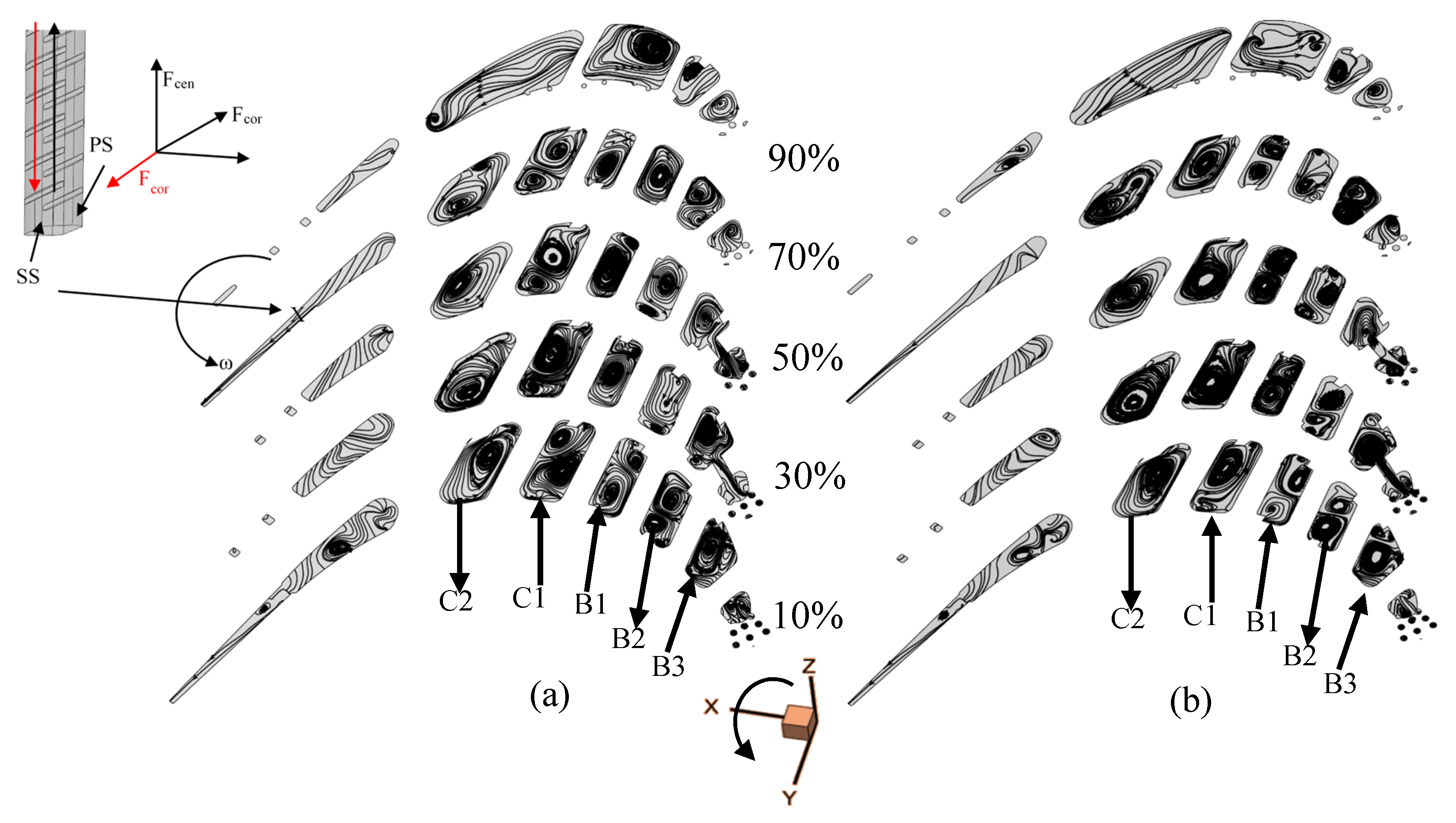
4.1. Flow Field Analysis

The Coriolis, centrifugal, and buoyancy forces of rotation significantly impact the flow field in the cooling passages of the rotor blade. These forces induce the generation of secondary flow to alter the coolant flow field, then affect heat transfer in the cooling passages. Coriolis forces are perpendicular to the direction of the coolant flow and are opposite in radially outward and inward flows. In this paper, Coriolis forces point toward the pressure surface in radially outward flow channels (B1, B3, and C1) and the suction surface in the radially inward flow channels (B2 and C2), as shown in Figure 6. The Coriolis and centrifugal forces and the temperature difference in the coolant flow all contribute toward generating the buoyancy force. Only the buoyancy force derived from centrifugal and Coriolis forces is discussed in this part.
Figure 6 shows the streamlines at different blade span locations of 10%, 30%, 50%, 70%, and 90% under rotating and stationary conditions. The arrow direction shows the cooling flow in a channel. Firstly, the internal cooling flow field in the radially outward flow channel (C1) of the blade is comparatively analyzed in detail from 10% span to 70% span under both conditions. The Coriolis force in the C1 channel causes the coolant to shift to the pressure surface. Therefore, the mainstream velocity and the circumferential velocity gradient increase near the pressure surface and decrease around the suction surface, enhancing and weakening the convective heat transfer capacity and the friction loss of the pressure surface and suction surface, respectively. The unbalanced cross-section Coriolis force induces the secondary flow in the C1 channel, and a counter vortex is generated from the pressure surface to the suction surface. The secondary flow brings the colder fluid to the pressure surface and the hotter fluid to the suction surface through C1 channel sidewalls, which further strengthens the pressure surface’s heat transfer and weakens the suction surface’s heat transfer. Therefore, the Coriolis force enhances and weakens the convective heat transfer capacity of the pressure surface and suction surface in the C1 channel, respectively, as does the buoyancy force derived by the Coriolis force in the C1 channel.
The buoyancy force derived by centrifugal force accelerates the low-density thermal fluid near the cooling channel walls along the rotational direction and the high-density colder fluid in the center of the cooling channels along the centrifugal path. In the C1 channel, the buoyancy force derived by centrifugal force hinders the thermal fluid flow near channel walls, weakening the convective heat transfer intensity on the channel walls.
The C2 and B2 channels both exhibit radial inward flow. The effect of Coriolis force and its induced buoyancy force on heat transfer in radial inward flow channels is opposite to that in radially outward flow channels, which enhance and reduce the heat transfer performance on the suction surface and the pressure surface of the blade, respectively. Furthermore, the centrifugal force accelerates the thermal fluid flow around channel walls and increases the convective heat transfer on the walls. The blade at 90% span includes 180° turns, and the Coriolis and buoyancy forces have the opposite effect on the internal coolant under rotating condition. The coolant flow is more disordered than that under the stationary condition, increasing the flow resistance and the heat transfer.

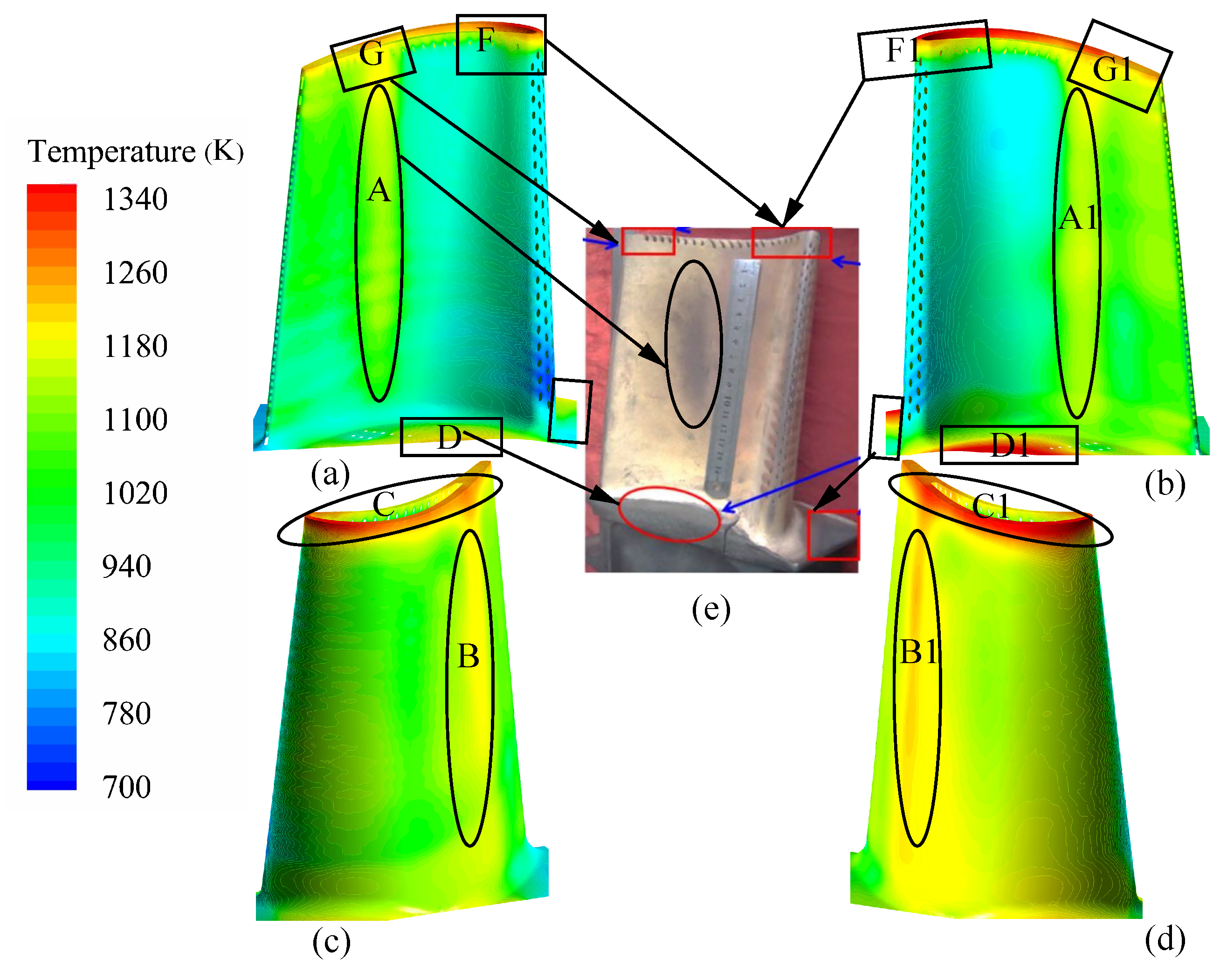
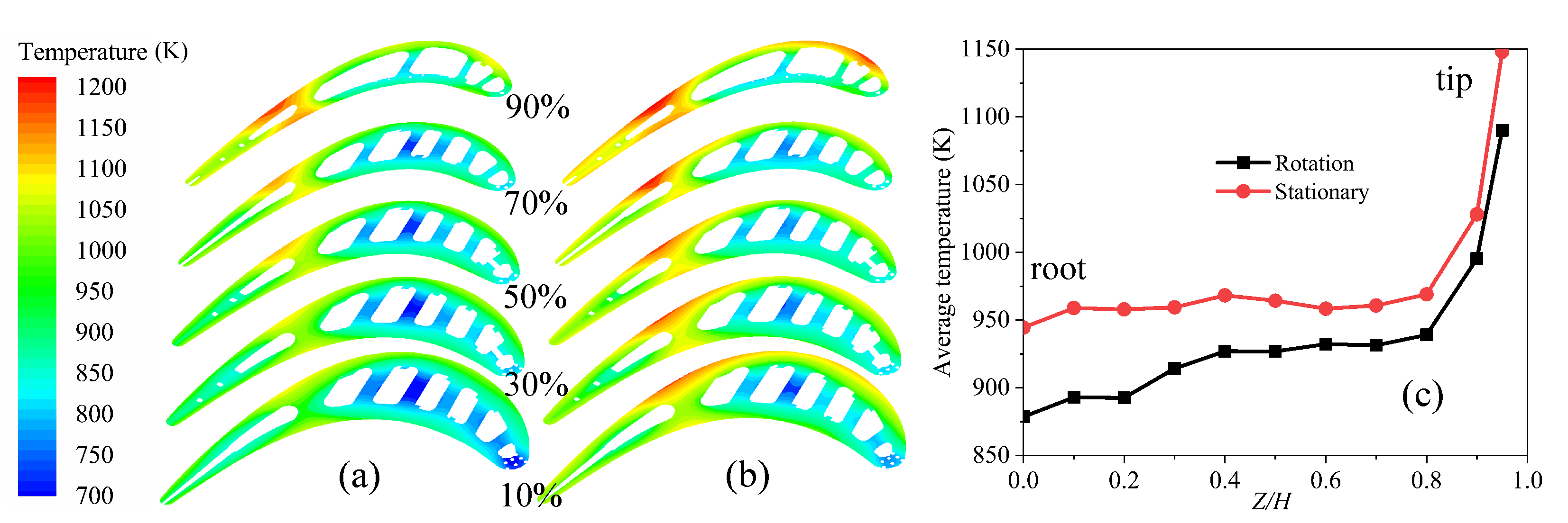
4.2. Heat Transfer Analysis

The nondimensional overall cooling efficiency ( ϕ ) relies on the high-temperature gas/coolant temperature and the flow velocity and is affected by heat conduction in the solid domain, which can be described as follows:
ϕ = T g T w T g T c
where T g and T c are the area-average temperature on the inlet of the high-temperature gas and coolant, respectively, and T w is the wall temperature of the blade.
Figure 7 shows the comparison of blade temperature distributions under both conditions. The rotor blade’s maximum, average, and minimum temperatures under the stationary condition are 1405 K, 1052 K, and 774 K, respectively. Under the rotating condition, the blade’s maximum, average, and minimum temperatures are reduced by 5%, 5.54%, and 6.83% compared with that under the stationary condition. The highest temperature difference of the blade under stationary and rotating conditions is 630 K and 613 K, respectively.
Figure 7a–d show the temperature distribution on the pressure surface and suction surface of the rotor blade under both conditions. It can be seen that the temperature on the blade surface increases with the mainstream flow direction, and high-temperature areas concentrate on the blade tip and root under both conditions. Under both conditions, the rotor blade’s highest temperature is located at the blade tip near the leading-edge region (C and C1) on the suction surface (Figure 7c,d). The locations of the high-temperature areas (A,D,G,F;A1,D1,G1,F1) are similar to those found from the actual service moving blade (Figure 7e) with similar boundary conditions and geometric shape under the rotating condition [32]. Because of the mainstream entrainment effect of the complex end-wall vortices, the film cooling on the blade tip and root is destroyed without adequate coolant coverage. There are strip-shaped high-temperature areas in area A on the pressure side and area B on the suction side under rotating conditions, as shown in Figure 7a,c. The blade has strip-shaped areas (A1 and B1) of a higher temperature under the stationary condition than under the rotating condition. These two areas (A and B or A1 and B1) are without effective cooling between the transition between the trailing edge and blade mid-chord (Figure 1). Therefore, adjusting the cooling structure on the trailing edge is necessary to reduce high temperature, by means such as adding through holes between the trailing edge and blade mid-chord. The temperature of the suction surface under the stationary condition is significantly higher than that under the rotating condition. However, there is little temperature variation on the pressure surface under the two conditions.
Figure 8a,b show the temperature distributions at different blade span locations of 10%, 30%, 50%, 70%m and 90%, which correspond to those in Figure 6. The low-temperature areas are the internal cooling channel sidewalls, especially the C1 (B1) channel sidewall. The coolant in those areas has minimal heat exchange with the high-temperature mainstream. The temperature of the blade gradually increases from the cooling channels to the outer surface under the two conditions. Figure 8c is the average temperature at different blade span locations under the two situations. The average temperature of the blade span increases slowly from the blade root to 80% span, but the temperature increases significantly at 90% span for less cooling air flow on the blade tip. However, the average temperature and temperature difference between the internal and outer surfaces at the different blade span locations under the rotating condition are lower than under the stationary condition. In brief, under the rotating condition, the maximum temperature of the blade is lower and the high-temperature area is smaller than that under the stationary condition.
As shown in Figure 9a,c, the overall cooling efficiency on the leading edge with film cooling (D) is the highest, which reaches 0.9. Moreover, the overall cooling efficiency deteriorates from the blade root to the blade tip. The overall cooling efficiency is lower on the mid-chord of the blade (A and B). Moreover, the overall cooling efficiency on the suction side is lower than that on the pressure side, especially on the tip of the blade (C). Together with Figure 9b,d, the overall cooling efficiency of the blade under the stationary condition is lower than that under the rotating condition, except for the E1 region on the pressure side. Under the stationary condition, a large amount of coolant flowing out from the film holes of the blade root is collected in E1 region; thus, the thermal insulation effectiveness is better.

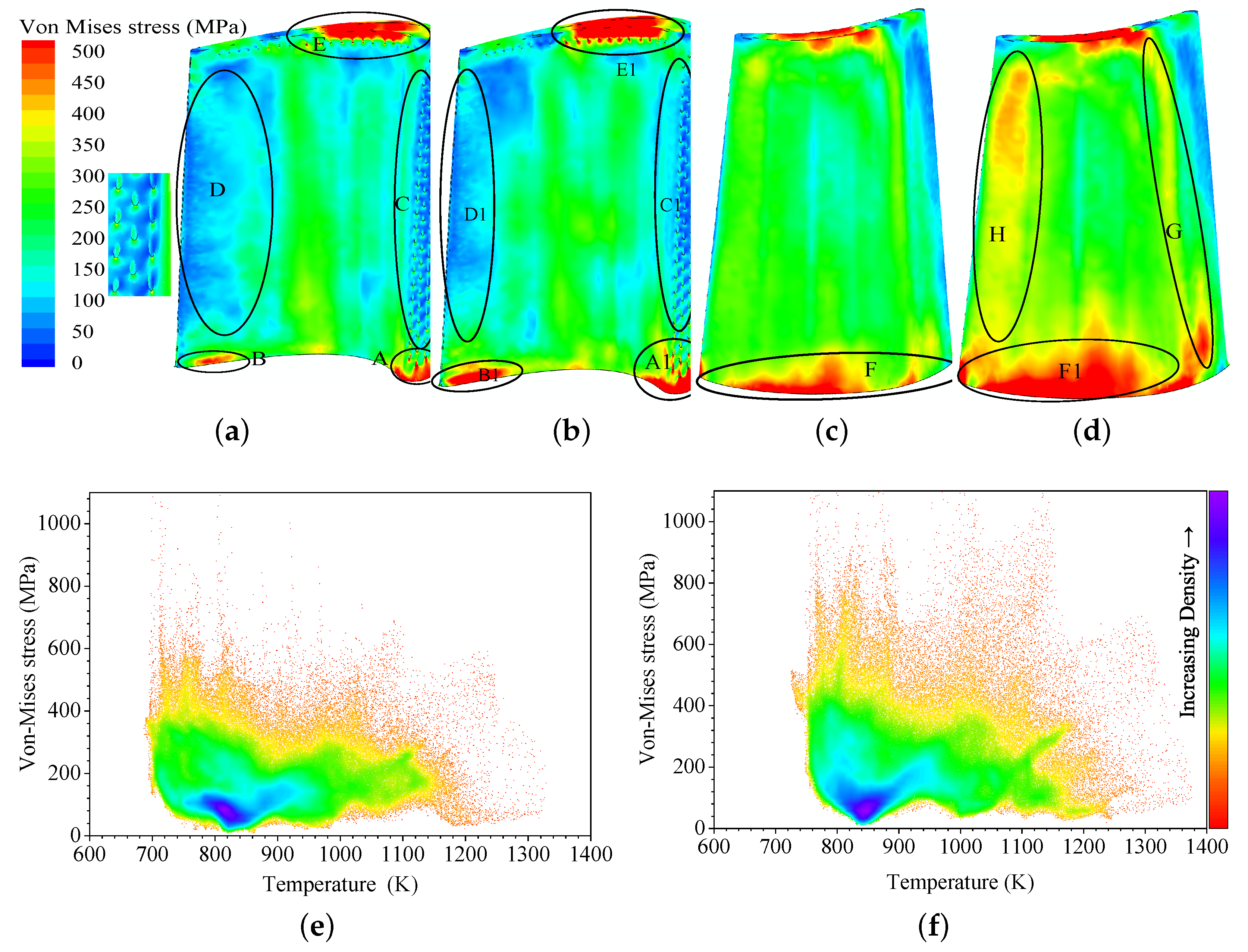
4.3. Thermal Stress Analysis

Figure 10a–d show the von Mises stress distributions of the rotor blade surface under rotating and stationary conditions. The thermal stress concentration occurs on the blade root (A, B and F), which is connected to the hub under the two conditions. Although the temperature of the blade root is lower, the higher temperature gradient and the complex cooling structures cause higher thermal stress [16,33]. In addition, thermal stress is also concentrated on the mid-chord region (E) of the blade tip, especially the film holes near the pressure surface under the stationary condition, because the film cooling on the blade pressure side and the grooved blade tip reduces the temperature and increases the temperature gradient. In contrast to the blade root, the blade tip with high thermal stress and high temperature deserves more attention, because the blade material yields decrease in stress with increasing temperature.
Under the rotating condition, the maximum von Mises stress value on the leading-edge region (A), trailing-edge region (B), and grooved-blade-tip region (E) are 858 MPa, 893 MPa, and 1204 MPa, respectively. The above three maximum von Mises stress values lie on the upstream edge of the film hole, the connection between the pin-fin and pressure surface, and the upstream edge of the film hole on the pressure surface, respectively. The von Mises stress distribution on the pressure side is more uneven than on the suction side, and the thermal stress value on the leading-edge region (C) and the trailing-edge region (D) is smaller than on the mid-chord region. However, the von Mises stress value on the blade suction side is more significant than on the pressure side. Under the stationary condition, the maximum von Mises stress value on the leading-edge region, trailing-edge region, and grooved-blade-tip region increases by 21%, 38%, and 21%, respectively, compared with that under the rotating condition. The locations of the above three maximum von Mises stress values are similar to those under the rotating condition. Compared with the rotating condition, the inhomogeneity value and distribution of the thermal stress of the blade root(F1), leading edge (H) and the trailing edge (G) on the suction side under the stationary condition are increased, and the thermal stress distribution on the pressure side undergoes a minor change. In conjunction with Figure 7, the high-thermal-stress regions do not entirely correspond to the high-temperature area. Therefore, we should not only pay attention to the high-temperature region of the blade, but also concentrate on the influence of the cooling structure on the thermal stress.
Figure 10e,f are density maps, which illustrate the correlation between thermal stress and the temperature of the rotor blade under the rotating and stationary conditions, respectively. The thermal stress distribution of the rotor blade concentrates below 600 MPa, with the temperature varying from 670 to 1200 K under the two conditions. The high-stress (>600 MPa) regions correspond to the low-temperature region from 670 to 970 K under the rotating condition. However, the high-stress (>600 MPa) areas correspond to the temperature region from 720 to 1145 K and more high-stress nodes under the stationary condition. Therefore, the maximum thermal stress and the thermal stress distribution of the rotor blade meet the design requirements under stationary conditions and also under the rotating condition.
The von Mises stress only reflects the combined effect of all principal stress and cannot provide the direction and magnitude of individual stresses. The RSS of 30 slip systems based on CPFEM is affected by the slip direction and material anisotropic behavior with crystal orientation. In addition, the crystal yield is controlled by the RSS instead of the equivalent von Mises stress [34]. Figure 11 shows the MRSS on the blade surface under stationary and rotating conditions. The positive and negative values represent tensile stress and compressive stress, respectively. The tensile stress and compressive stress appear alternately on the blade, and there are numerous tensile and compressive stress interfaces under both conditions. Under the rotating condition, the amplitudes of MRSS on the grooved blade tip (B) and the leading edge of the blade root (A) are 581 MPa and 627 MPa, respectively. The MRSS on the pressure surface is smaller and more evenly distributed than that on the suction surface from the 10% span to the 90% span of the blade. On the other hand, the MRSS is large and extends from the blade root to approximately 50% span in the C region (Figure 11a) on the pressure surface. Compared with the blade pressure surface, the tension and compression stress are distributed alternately with strips (D/E/F regions) from the blade root to the tip on the blade suction surface. The amplitudes of MRSS under the stationary condition on the grooved blade tip and the leading edge of the blade root increase by 20% and 31%, respectively, compared with that under the rotating condition. In addition, the distribution inhomogeneity of MRSS is increased on the blade surface under the stationary condition compared with under the rotating condition, especially on the suction side. Compared with the von Mises stress distribution of the rotor blade, the MRSS can clearly express the distribution of tensile and compressive stress on the rotor blade. The interfaces between higher tensile and compressive stresses on the blade also need to be emphasized during the rotor blade design phase, in addition to the high-temperature and high-stress regions.
Figure 12 shows the DSS under stationary and rotating conditions. The activation of the slip system of a crystal blade is affected by temperature and reaches a certain critical stress in different slip families. In addition, the activation of DSS inhibits the actuation of new slip systems [24] . Combined with the analysis of Figure 7, the <110> 111 slip system and <112> 111 slip system mainly control the activation of the slip system in the low-temperature region under rotating and stationary conditions. As the temperature increases, the <110> 100 slip system control region dominates on the blade. Blade damage mainly occurs in the regions where the DSS is activated, and crack initiation takes place at the interface of different DSSs.
Figure 13 gives the temperature, von Mises stress, MRSS, and DSS on the outer surface at blade spans of 10% and 50% under rotating and stationary conditions. In the two conditions, the distribution law of the above variables along the 10% and 50% blade spans is similar. The temperature of the blade surface is concentrated between 770 and 1070 K, and the von Mises stress is below 400 MPa along the 10% and 50% blade spans. The von Mises stress is positively correlated with the temperature gradient on the pressure and suction surfaces of the blade along the span. In addition, the value of MRSS is concentrated within 200 MPa, and the thermal stress on the pressure surface is less than that on the suction surface. The <110> 111 and <112> 111 slip systems are dominant at the 10% span and 50% span, and the <110> 100 slip system primarily appears on the trailing-edge region.

5. Conclusions

CHT analysis and a sequentially coupled thermal–mechanical analysis are used to investigate the heat transfer and thermal stress distribution of a high-temperature Ni-based superalloy turbine rotor blade with highly integrated and efficient cooling structures under both rotating and stationary conditions with actual boundary conditions. The crystal plasticity finite element method, by considering the material anisotropy, is employed to calculate the maximum resolved shear stress and its corresponding dominant slip system to analyze dislocations of the rotor blade. The essential conclusions are itemized as follows:
  • The inherent forces (Coriolis, centrifugal, and buoyancy forces) of rotation deflect the coolant flow to a specific wall and induce the generation of secondary flow, which increases the complexity of the vortex structure in the cooling channels of the rotor blade, differentiated from the stationary condition. Simultaneously, the coolant turbulence is enhanced; thus, the heat transfer performance of the rotor blade is improved with higher overall cooling efficiency under the rotating condition. The maximum temperature of the blade under the rotating condition is reduced by 5% compared with that under the stationary condition. Therefore, the highest temperature of the blade will satisfy the design requirements under the rotating condition if these design requirements are met under the stationary condition.
  • The von Mises stress concentrations locate where the blade root connects to the hub and the film holes near the leading-edge region of the blade root and the mid-chord of the grooved blade tip under the two conditions. However, the maximum magnitude of the von Mises stress of the rotor blade under the rotating condition reduces by 21% compared with that under the stationary condition. The thermal stress distribution on the blade suction surface is more uniform under the rotating condition than under the stationary condition. On the basis that the rotor blade meets the highest temperature design requirements, the thermal stress distribution of the blade in conjunction with the high-temperature gradient regions under the rotating condition is better than that under stationary conditions.
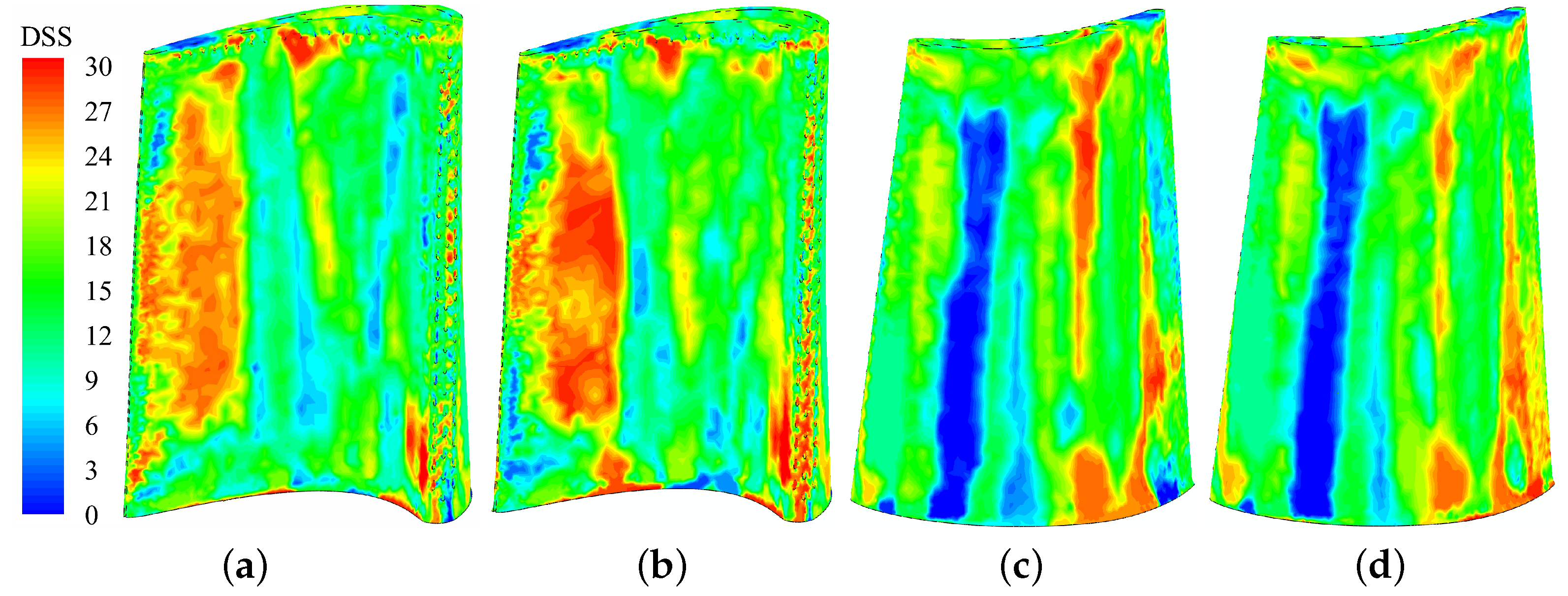
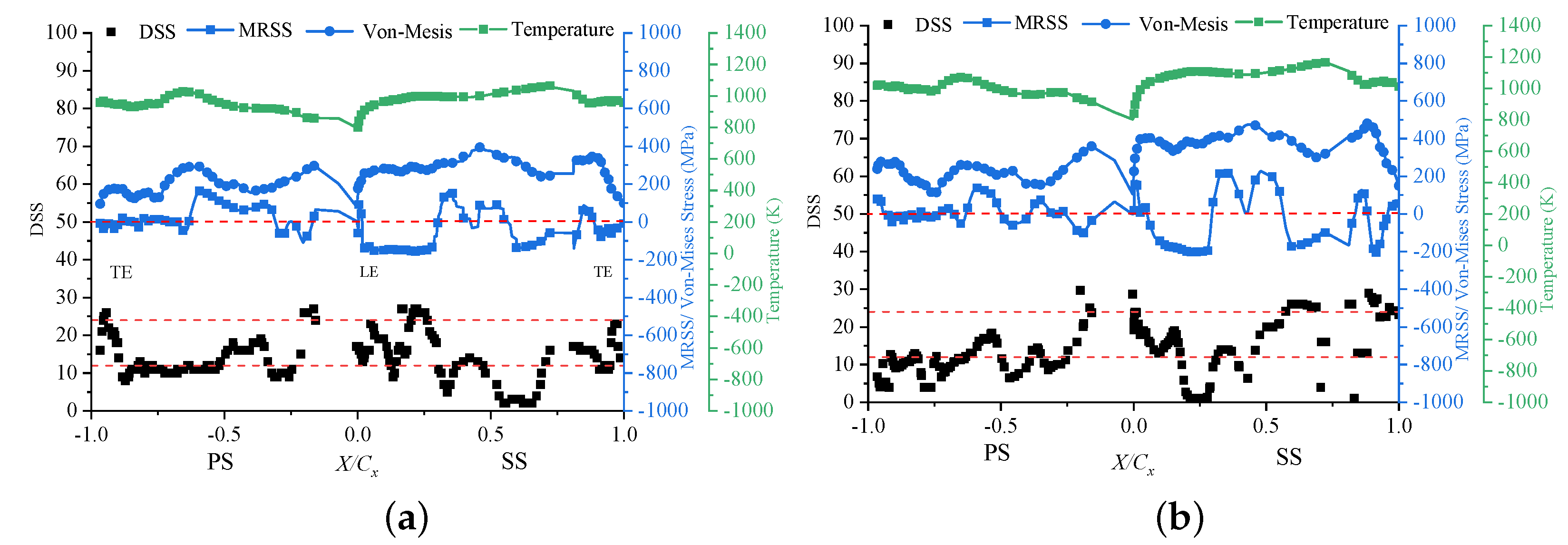
  • The maximum value of the MRSS regions does not entirely correspond to the von Mises stress concentration regions under rotating and stationary conditions. The positive and negative striped values of MRSS appear alternately on the blade surface, on which the MRSS distribution is more inhomogeneous than the von Mises stress under both conditions. The dominant slip system of the rotor blade is the dodecahedral slip family (<112> 111 ) under both conditions. Compared with the von Mises stress results, the mid-chord of the suction surface also deserves attention for the larger MRSS and interface of different dominant slip systems under both conditions, especially under the stationary condition.

Author Contributions

Conceptualization, X.Q., P.Y. and W.H.; data curation, X.Q.; formal analysis, X.Q. and X.W.; funding acquisition, P.Y. and W.H.; investigation, X.Q.; methodology, X.Q., P.Y. and W.H.; project administration, P.Y.; resources, P.Y., X.W. and W.H.; software, X.Q.; supervision, P.Y., X.W., and W.H.; validation, X.Q. and X.W.; writing—original draft, X.Q.; writing—review and editing, X.Q. and P.Y. All authors have read and agreed to the published version of the manuscript.

Funding

This research was funded by the National Natural Science Foundation of China, grant number 52076051.

Institutional Review Board Statement

Not applicable.

Informed Consent Statement

Not applicable.

Data Availability Statement

Not applicable.

Conflicts of Interest

The authors declare no conflict of interest.

Abbreviations

The following abbreviations are used in this manuscript:
C3D4Four-node linear tetrahedral element
CHTConjugate heat transfer
CPFEMCrystal plasticity finite element simulation method
DSDirectionally solidified
DSSDominant slip system
MRSSMaximum resolved shear stress
RSSResolved shear stress

References

  1. Han, J.-C. Advanced cooling in gas turbines 2016 Max Jakob memorial award paper. J. Heat Transf. 2018, 140, 113001. [Google Scholar] [CrossRef]
  2. Wagner, J.; Johnson, B.; Kopper, F. Heat transfer in rotating serpentine passages with smooth walls. J. Turbomach. 1991, 113, 321–330. [Google Scholar] [CrossRef]
  3. Wagner, J.; Johnson, B.; Graziani, R.; Yeh, F. Heat transfer in rotating serpentine passages with trips normal to the flow. J. Turbomach. 1992, 114, 847–857. [Google Scholar] [CrossRef]
  4. Al-Qahtani, M.; Jang, Y.-J.; Chen, H.-C.; Han, J.-C. Prediction of flow and heat transfer in rotating two-pass rectangular channels with 45-deg rib turbulators . J. Turbomach. 2002, 124, 242–250. [Google Scholar] [CrossRef]
  5. Dutta, S.; Han, J.-C. Local heat transfer in rotating smooth and ribbed two-pass square channels with three channel orientations. J. Heat Transfer. 1996, 118, 578–584. [Google Scholar] [CrossRef]
  6. Al-Hadhrami, L.; Han, J.-C. Effect of rotation on heat transfer in two-pass square channels with five different orientations of 45 angled rib turbulators. Int. J. Heat Mass Transf. 2003, 46, 653–669. [Google Scholar] [CrossRef]
  7. Parsons, J.A.; Han, J.-C. Rotation effect on jet impingement heat transfer in smooth rectangular channels with heated target walls and radially outward cross flow. Int. J. Heat Mass Transf. 1998, 41, 2059–2071. [Google Scholar] [CrossRef]
  8. Wright, L.M.; Lee, E.; Han, J.-C. Effect of rotation on heat transfer in rectangular channels with pin-fins. J. Thermophys. Heat Transf. 2004, 18, 263–272. [Google Scholar] [CrossRef]
  9. Griffith, T.S.; Al-Hadhrami, L.; Han, J.-C. Heat transfer in rotating rectangular cooling channels AR = 4 with dimples. J. Turbomach. 2003, 125, 555–563. [Google Scholar] [CrossRef]
  10. Ahn, J.; Schobeiri, M.; Han, J.-C.; Moon, H.-K. Film cooling effectiveness on the leading edge region of a rotating turbine blade with two rows of film cooling holes using pressure sensitive paint. J. Heat Transf. 2006, 128, 879–888. [Google Scholar] [CrossRef]
  11. Rezasoltani, M.; Lu, K.; Schobeiri, M.T.; Han, J.-C. A combined experimental and numerical study of the turbine blade tip film cooling effectiveness under rotation condition. J. Turbomach. 2015, 137, 051009. [Google Scholar] [CrossRef]
  12. Rezasoltani, M.; Schobeiri, M.; Han, J. Experimental investigation of the effect of purge flow on film cooling effectiveness on a rotating turbine with non-axisymmetric endwall contouring. In Turbo Expo: Power for Land, Sea, and Air; American Society of Mechanical Engineers: New York, NY, USA, 2013; Volume 55157, p. V03BT13A033. [Google Scholar]
  13. Yeranee, K.; Yu, R. A review of recent studies on rotating internal cooling for gas turbine blades. Chin. J. Aeronaut. 2021, 34, 85–113. [Google Scholar] [CrossRef]
  14. Rao, V.N.B.; Kumar, I.N.; Prasad, K.B. Failure analysis of gas turbine blades in a gas turbine engine used for marine applications. Int. J. Eng. Sci. Technol. 2014, 6, 43–48. [Google Scholar]
  15. Kim, K.M.; Park, J.S.; Lee, D.H.; Lee, T.W.; Cho, H.H. Analysis of conjugated heat transfer, stress and failure in a gas turbine blade with circular cooling passages. Eng. Fail. Anal. 2011, 18, 1212–1222. [Google Scholar] [CrossRef]
  16. Ziaei-Asl, A.; Ramezanlou, M.T. Thermo-mechanical behavior of gas turbine blade equipped with cooling ducts and protective coating with different thicknesses. Int. J. Mech. Sci. 2019, 150, 656–664. [Google Scholar] [CrossRef]
  17. Staroselsky, A.; Martin, T.; Cassenti, B. Transient thermal analysis and viscoplastic damage model for life prediction of turbine components. J. Eng. Gas Turbines Power 2015, 137, 042501. [Google Scholar] [CrossRef]
  18. Wang, J.; Wei, D.; Wang, Y.; Jiang, X. A fatigue life prediction model based on modified resolved shear stress for nickel-based single crystal superalloys. Metals 2019, 9, 180. [Google Scholar] [CrossRef] [Green Version]
  19. Hou, N.; Wen, Z.; Yu, Q.; Yue, Z. Application of a combined high and low cycle fatigue life model on life prediction of SC blade. Int. J. Fatigue 2009, 31, 616–619. [Google Scholar] [CrossRef]
  20. Hou, N.; Gou, W.; Wen, Z.; Yue, Z. The influence of crystal orientations on fatigue life of single crystal cooled turbine blade. Mater. Sci. Eng. A 2008, 492, 413–418. [Google Scholar] [CrossRef]
  21. Wen, Z.; Hou, N.; Wang, B.; Yue, Z. Crystallographic life model for single crystal turbine blade and validation by the miniature specimens cut from the turbine blades. Multidiscip. Model. Mater. Struct. 2010, 6, 508–529. [Google Scholar] [CrossRef]
  22. Liu, Z.; Yue, Z.; Zhi, X.; Hou, N. Influence of dimension variation on strength and fatigue life of single crystal cooled blade. Rare Met. Mater. Eng. 2013, 42, 1563–1567. [Google Scholar]
  23. Hou, N.; Yu, Q.; Wang, B.; Yue, Z. An equivalent model for mechanical analysis of single crystal cooled blade with film cooling holes using crystal plasticity. Eng. Fract. Mech. 2010, 77, 1379–1385. [Google Scholar] [CrossRef]
  24. Arakere, N.; Siddiqui, S.; Ebrahimi, F. Evolution of plasticity in notched Ni-base superalloy single crystals. Int. J. Solids Struct. 2009, 46, 3027–3044. [Google Scholar] [CrossRef] [Green Version]
  25. Mao, H.; Wen, Z.; Yue, Z.; Wang, B. The evolution of plasticity for nickel-base single crystal cooled blade with film cooling holes. Mater. Sci. Eng. A 2013, 587, 79–84. [Google Scholar] [CrossRef]
  26. John, B.; Senthilkumar, P.; Sadasivan, S. Applied and theoretical aspects of conjugate heat transfer analysis: A review. Arch. Comput. Methods Eng. 2019, 26, 475–489. [Google Scholar] [CrossRef]
  27. Dong, P.; Wang, Q.; Guo, Z.; Huang, H.; Feng, G. Conjugate calculation of gas turbine vanes cooled with leading edge films. Chin. J. Aeronaut. 2009, 22, 145–152. [Google Scholar] [CrossRef] [Green Version]
  28. ANSYS. ANSYS CFX-Solver Modeling Guide; ANSYS: Canonsburg, PA, USA, 2020. [Google Scholar]
  29. Roters, F.; Eisenlohr, P.; Hantcherli, L.; Tjahjanto, D.D.; Bieler, T.R.; Raabe, D. Overview of constitutive laws, kinematics, homogenization and multiscale methods in crystal plasticity finite-element modeling: Theory, experiments, applications. Acta Mater. 2010, 58, 1152–1211. [Google Scholar] [CrossRef]
  30. Li, Z.; Gao, H.; Wen, Z.; Yang, Y.; Zhang, Y.; Ai, X.; Yue, Z. Microcrack initiation behavior around film cooling holes in a Ni-based single crystal: In situ observation and crystal plastic analysis. Mater. Sci. Eng. A 2020, 771, 138609. [Google Scholar] [CrossRef]
  31. Shenoy, M.M. Constitutive Modeling and Life Prediction in Nickel-Base Superalloys; Georgia Institute of Technology: Atlanta, Georgia, 2006. [Google Scholar]
  32. Cai, L.; He, Y.; Wang, S.; Li, Y.; Li, F. Thermal-Fluid-Solid coupling analysis on the temperature and thermal stress field of a Nickel-Base superalloy turbine blade. Materials 2021, 14, 3315. [Google Scholar] [CrossRef]
  33. Stewart, C. Tertiary Creep Damage Modeling of a Transversely Isotropic Ni-Based Superalloy. Master’s Thesis, University of Central Florida, Orlando, FL, USA, 2009. [Google Scholar]
  34. Zhai, Y.; Khan, M.K.; Correia, J.; deJesus, A.M.; Huang, Z.; Zhang, X.; Wang, Q. Effect of secondary crystal orientations on the deformation anisotropy for nickel-based single-crystal plate with notch feature. J. Strain Anal. Eng. Des. 2019, 54, 54–64. [Google Scholar] [CrossRef]
Figure 1. The cooling structure schematic of a high-temperature Ni-based superalloy turbine rotor blade: W1–W3 indicate 180° turns in the serpentine passages; A–D indicate the different cooling structures.
Energies 15 04972 g001
Figure 2. Local computational elements for CHT analysis: (a) pin-fin in the trailing-edge region; (b) rib-turbulated serpentine channel; (c) film-cooling holes in the leading-edge region.
Energies 15 04972 g002
Figure 3. Grid independence verification for CHT analysis: (a) the maximum and average temperature for the blade; (b) the overall cooling efficiency at the 50% blade span, C x is the axial chord length of the 50% blade span.
Energies 15 04972 g003
Figure 4. Temperature-dependent material properties of DS GTD-111: (a) thermal conductivity and expansion coefficient; (b) elastic modulus, shear modulus, and yield strength [31].
Energies 15 04972 g004
Figure 5. (a) Finite element mesh and the constraint of the turbine blade for thermal stress analysis; (b) Von Mises stress at 50% of the blade span of different numbers of solid elements for grid independence verification.
Energies 15 04972 g005
Figure 6. The streamlines for blade spans from 10% to 90% under (a) rotating condition; (b) stationary condition.
Energies 15 04972 g006
Figure 7. The temperature distribution of the blade: (a) pressure side and (c) suction side under the rotating condition; (b) pressure side and (d) suction side under the stationary condition; (e) the pressure side of actual service moving blade (Reprinted with permission from Ref. [32], 2021, Cai et al.) (A(A1)–G(G1) represent the local high-temperature areas).
Energies 15 04972 g007
Figure 8. The temperature distribution of the blade spans: (a) rotating condition; (b) stationary condition; (c) average temperature along the blade span.
Energies 15 04972 g008
Figure 9. The overall cooling efficiency of the blade: (a) pressure side and (c) suction side under the rotating condition; (b) pressure side and (d) suction side under the stationary condition (A(A1)–C(C1) represent low–heat transfer areas; D(D1) and E(E1) represent high–heat transfer areas).
Energies 15 04972 g009
Figure 10. Von Mises stress distribution of the rotor blade: (a) pressure side, (c) suction side, and (e) thermo-stress state under the rotating condition; (b) pressure side, (d) suction side and (f) thermo-stress state under the stationary condition (A,B and E–H show the local stress concentration areas; C and D show low-stress areas).
Energies 15 04972 g010
Figure 11. MRSS distribution of the rotor blade: (a) pressure side and (c) suction side under the rotating condition; (b) pressure side and (d) suction side under the stationary condition (A–F indicate the local high MRSS areas).
Energies 15 04972 g011
Figure 12. DSS distribution of the blade: (a) pressure side and (c) suction side under the rotating condition; (b) pressure side and (d) suction side under the stationary condition.
Energies 15 04972 g012
Figure 13. Distribution of temperature, DSS, von Mises stress, and MRSS on the outer surface of the blade: (a) 10% span and (c) 50% span under the rotating condition; (b) 10% span and (d) 50% span under the stationary condition.
Energies 15 04972 g013aEnergies 15 04972 g013b
Table 1. Inlet boundary conditions of high-temperature gas and coolant under rotating and stationary conditions.
P total , g ( MPa ) T total , g ( K ) P total , cool 1 ( MPa ) T total , cool 1 ( K ) P total , cool 2 ( MPa ) T total , cool 2 ( K )
Rotating 0.95 (Relative)1461 (Relative) 1.47 657 1.37 657
Stationary 0.95 1471 1.4 657 1.4 657
Publisher’s Note: MDPI stays neutral with regard to jurisdictional claims in published maps and institutional affiliations.

