Abstract
The heat pump system has been widely used in residential and commercial applications due to its attractive advantages of high energy efficiency, reliability, and environmental impact. The massive exergy loss during the isenthalpic process in the expansion valve is a major drawback of the heat pump system. Therefore, the Tesla turbine exergy analysis in terms of transiting exergy efficiency is investigated and integrated with the transcritical heat pump system. The aim is to investigate the factors that reduce exergy losses and increase the coefficient of performance and exergy efficiency. The contribution of this paper is twofold. First, a three-dimensional numerical analysis of the supercritical CO2 flow simulation in the Tesla turbine in three different geometries is carried out. Second, the effect of the Tesla turbine on the coefficient of performance and exergy efficiency of the heat pump system is investigated. The effect of the rotor speed and disk spacing on the Tesla turbine power, exergy loss, and transiting exergy efficiency is investigated. The results showed that at a lower disk spacing, the turbine produces higher specific power and transiting exergy efficiency. In addition, the coefficient of performance (COP) and exergy efficiency improvement in the heat pump system combined with the Tesla turbine are 9.8% and 28.9% higher than in the conventional transcritical heat pump system, respectively.
1. Introduction
The concern of energy saving continues to rise due to the cost of energy and the reducing sources of fossil fuel. Besides, the heat pump system is capable of working under various heat sources and is beneficial for both residential and industrial applications. The great potential of energy saving of the heat pump system has gained much attention, and many researchers have been attempting to improve the overall efficiency of the heat pump system. Despite the high energy efficiency of the heat pump system, there is one issue regarding the huge exergy loss or irreversibility during the isenthalpic process in the throttling valve. Generally, the heat pump system is composed of a compressor, gas cooler, evaporator, and expansion valve. Furthermore, many different expansion devices, such as expansion valve, ejector [1,2,3], vortex tube [4,5], and Tesla turbine [6], have been integrated with the heat pump system. The heat pump performance relies on the optimum gas cooler pressure, so the expansion device plays an important role.
In the conventional heat pump cycle, the pressure difference between the condenser and evaporator is small, so the exergy loss in the expansion valve is negligible. However, in the transcritical heat pump cycle, the higher-pressure difference causes higher exergy loss, so choosing the appropriate expansion device is vital. The ejector was introduced as an alternative method to decrease the expansion loss, and it attracts many researchers’ attention [3,7,8,9,10]. Fangtian and Yitai [11] compared the ejector and throttling valve performance in the heat pump cycle. Their results showed that the ejector reduces 25% of the exergy losses and improves the COP of the heat pump cycle by up to 30%. Xing et al. [12] proposed two ejectors as expansion devices for a two-stage heat pump cycle to enhance the cycle performance, and based on their simulation, COP increased by more than 10.5%. Taslimi Taleghani et al. [13] optimized the two-phase ejector heat pump system with an ejector that improves the COP and heat capacity by up to 12% and 25%, respectively, compared with the basic cycle. Even though the ejector reduces the compressor power due to pressure augmentation at the compressor inlet, the higher ejector efficiency occurs at the lower gas cooler optimum pressure rather than the basic cycle [13,14]. In addition, computational fluid dynamics (CFD) modeling of a two-phase ejector indicated that droplets have a negative effect on the ejector performance [15]. The vortex tube is the second device that was proposed as an expansion device. The vortex tube is the second expansion device that is able to produce the hot and cold streams simultaneously. The vortex tube was invented in 1933, and since then, it has been used as a cooling device and gas-type separation [16] and it has been analyzed experimentally [17,18,19] and numerically [20,21,22]. The vortex tube as an expansion valve was introduced in [1,4,5,23,24]. Groll et al. [23] analyzed the vortex tube application in the heat pump cycle, and based on their findings, the COP of the heat pump cycle was increased by up to 37% when the vortex tube efficiency was 100%. Sarkar [4] investigated two different models of the heat pump cycle integrated with the vortex tube, namely, the Maurer model and the Keller model. The maximum COP improvement varied from 0.3% to 18.7% and 0% to 17.8% for the Maurer and Keller models, respectively. Even though much research indicates the COP improvement of the heat pump cycle integrated with the vortex tube, there are no experimental results regarding the utilization of the vortex tube in the heat pump system. An experimental study of two-phase propane indicated that when the quality of the working fluid is less than 0.8, the temperature separation diminishes rapidly [25], and another experimental research on steam showed that no energy is separated when the working fluid quality is less than approximately 0.98 [26]. The greater pressure difference between the gas cooler and evaporator leads to greater exergy losses, making work recovery more beneficial. The Tesla turbine is an alternative method for work recovery [6]. The application of the Tesla turbine is not impressive compared with the other turbomachinery device; however, in some situations, such as the presence of the second phase in the working fluid, the conventional turbomachinery devices are not suitable and the Tesla turbine is an appropriate device [27,28,29]. Yang et al. [30] applied the first and second laws of thermodynamics to the heat pump integrated with the expander, and their results showed 33% and 30% improvements on the COP and exergy efficiency, respectively. For the first time, the capacity of the Tesla turbine as an expansion valve was illustrated by Aghagoli and Sorin [6], who showed a 16.3% COP improvement.
In this paper, a thermodynamic analysis on the transcritical heat pump system coupled with the Tesla turbine in a term of COP and exergy efficiency is investigated. The effect of rotor speed and disk spacing on the Tesla turbine power production, specific power, exergy loss, and transiting exergy efficiency is investigated. A 3D CFD simulation of the Tesla turbine is performed with the ANSYS CFX solver. The CFD results of the 3D simulation of the Tesla turbine are entered into the heat pump system, and the effect of the Tesla turbine on the overall COP and exergy efficiency of the TeslaHPS is discussed.
2. Heat Pump Cycle Description
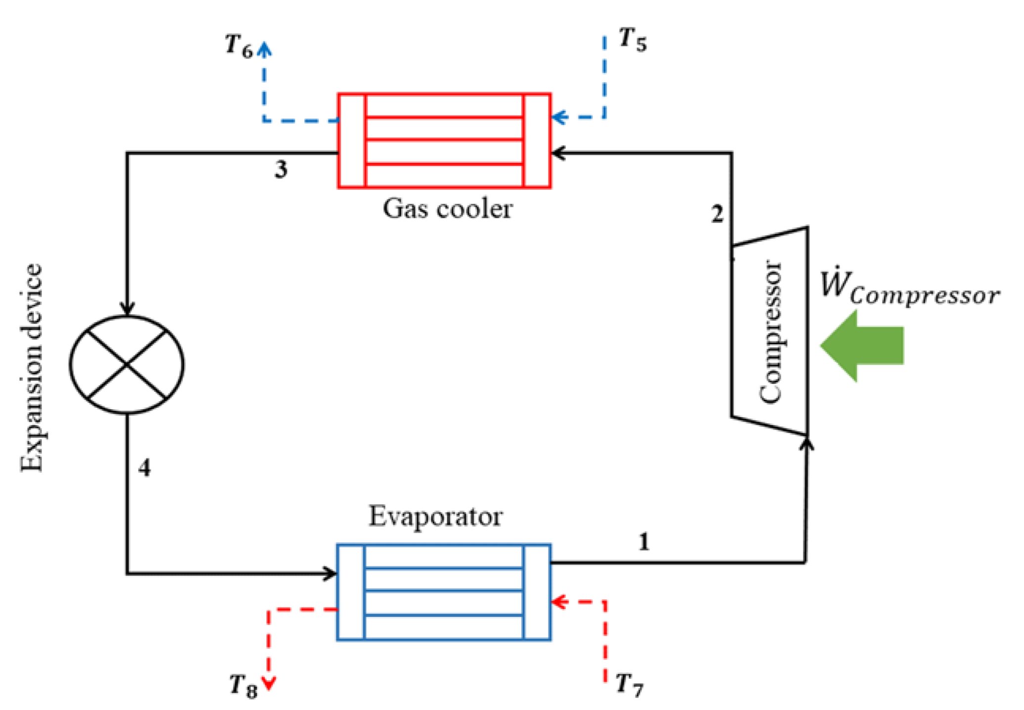
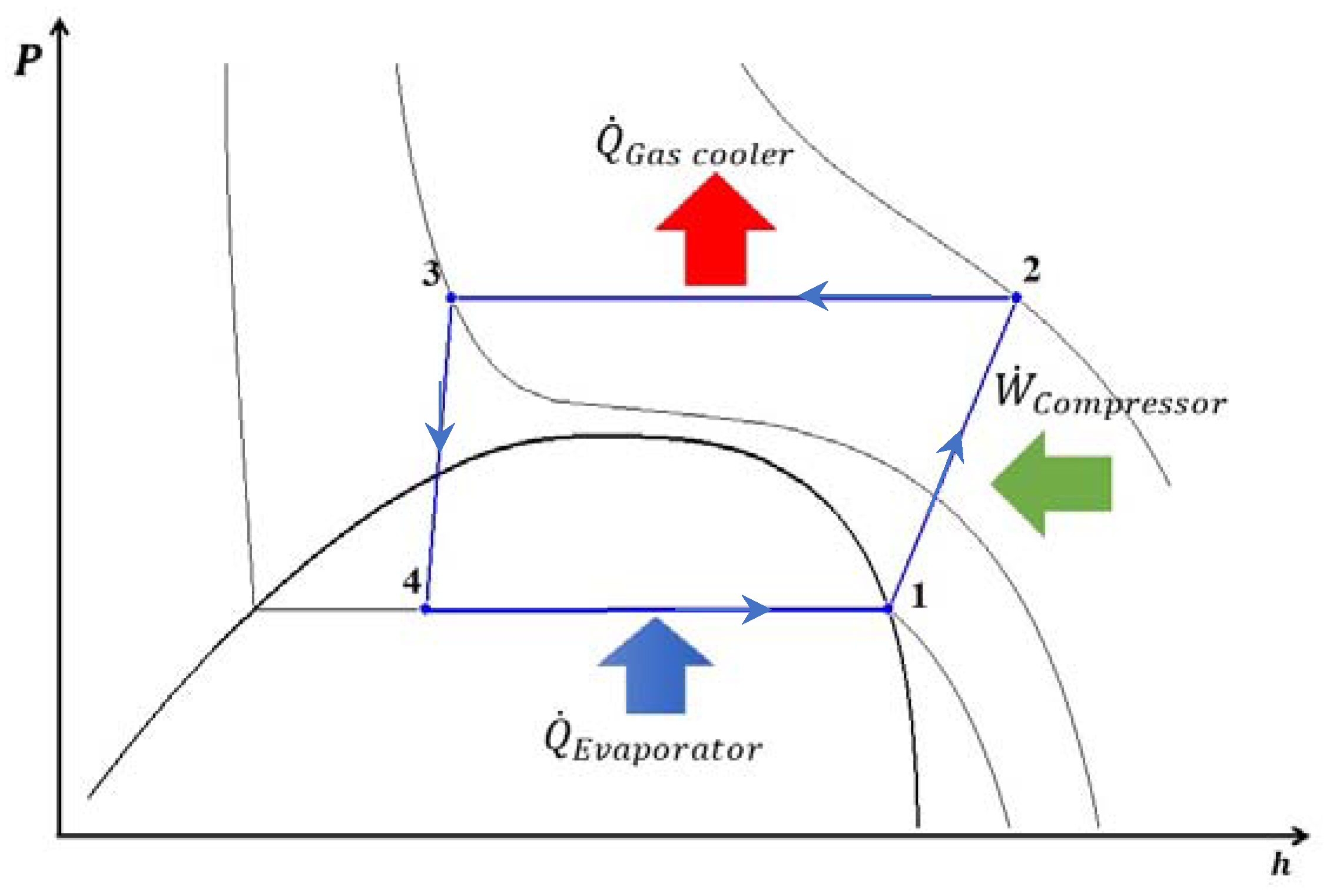
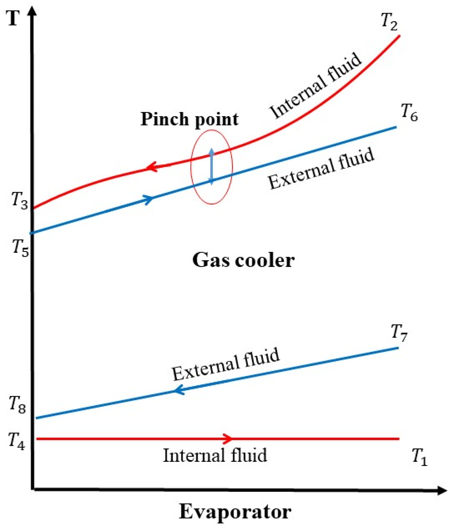
Schematic and P-h diagrams of the heat pump system are illustrated in Figure 1 and Figure 2, respectively. The process starts at stat 1 and ends at stat 4. The temperature evolution in the gas cooler and evaporator is illustrated in Figure 3. In the evaporator, CO2 evaporates as heat is received from an external fluid whose temperature drops from T7 to T8. At the evaporator outlet, the CO2 state is assumed to be saturated vapor and enters the compressor. The pressure and temperature of CO2 increase after the compressor and exceed the critical point. In the isobaric process, assuming that the pressure losses are neglected, the CO2 temperature decreases due to the heat rejection to the external fluid whose temperature rises from T5 to T6. CO2 expands in the expansion device, and its pressure and temperature decrease, and eventually, it enters the evaporator. The following assumptions are considered to analyze this cycle:
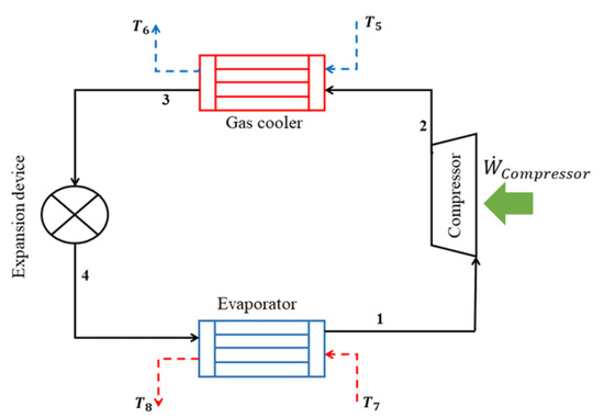
Figure 1.
Schematic of the heat pump cycle integrated with the expansion device.
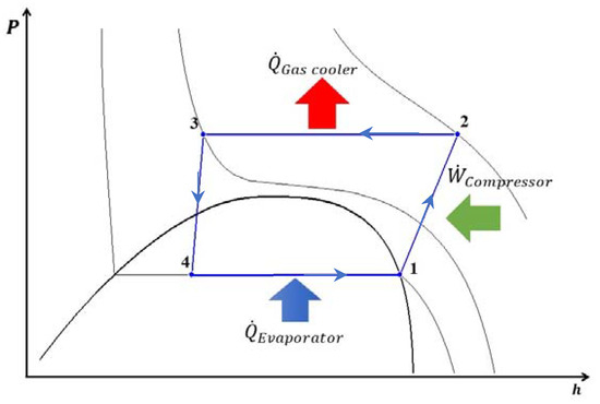
Figure 2.
P-h diagram of the heat pump cycle integrated with the expansion device.
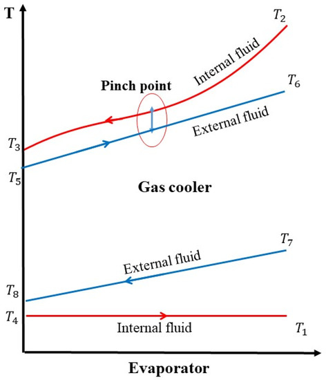
Figure 3.
Temperature evolution in the gas cooler and evaporator.
- There is no heat loss to the environment.
- The heat pump cycle operates in a steady-state condition.
- The pinch point is 5 K, and water is an external fluid.
The total of exergy losses of the heat pump system is defined as a summation of exergy loss of all components present in Table 1:

Table 1.
Thermodynamic Analysis of heat pump system components.
The COP of the Tesla heat pump system (TeslaHPS) is calculated as:
The exergy efficiency of the TeslaHPS is defined as follows:
The transiting exergy efficiency is given as [31]:
where and are the exergy produced and exergy consumed in the process. is the exergy that has not undergone transformation within an analyzed process. , , and
the Tesla turbine can be calculated as [31] in the case of the expansion process operating above T0:
, , and
the exergy produced and consumed and transiting exergy within the Tesla turbine, respectively.
The Grassmann exergy efficiency is given as:
It can be noticed that the exergy losses can be calculated by subtracting the numerator from the denominator in Equation (4). The details regarding the transiting exergy efficiency can be found in references [20,31].
3. CFD Model
Computational fluid dynamic (CFD) assists the researcher to understand the phenomena of fluid flow inside the domain of study based on the conservation of mass, momentum, and energy. Even though the CFD is a useful tool in simulating fluid motion, wrong assumptions lead to inaccurate results. Therefore, the following steps must be considered correctly: accurate working fluid, state equation, appropriate turbulence model, boundary condition, and grid independence study. In this study, the thermodynamic modeling of the Tesla turbine is considered; however, more details about the CFD modeling can be found in [6].
3.1. Carbon Dioxide Thermodynamic Properties
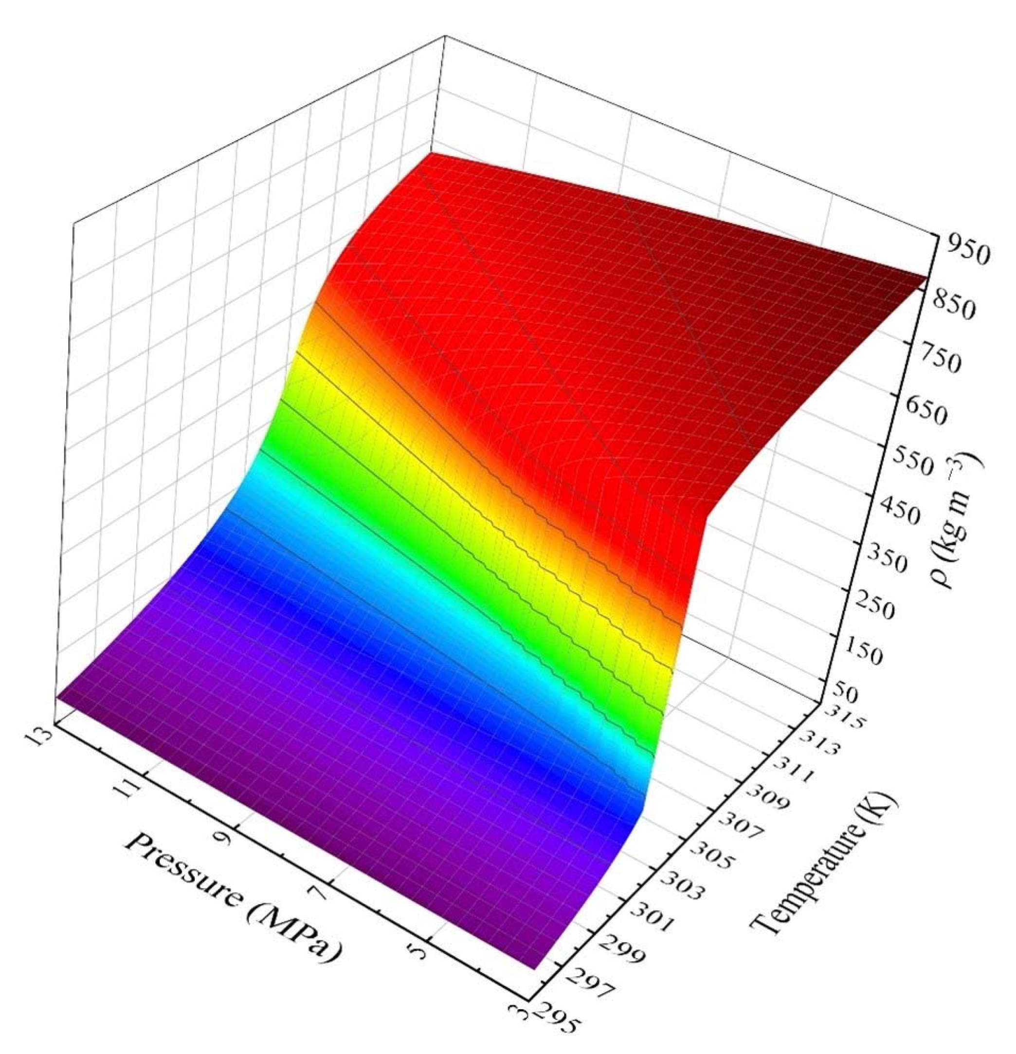
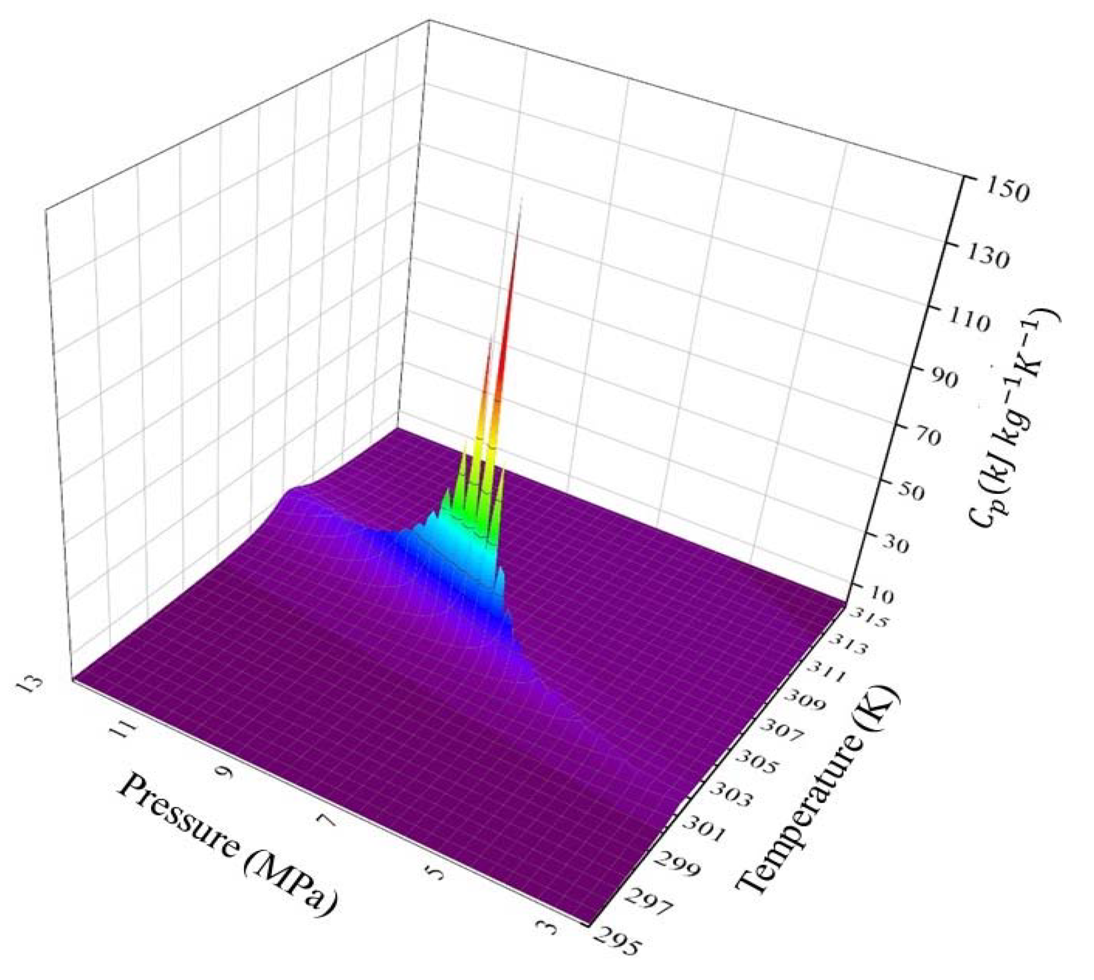
Figure 4 and Figure 5 illustrate the density (ρ) and the specific heat at a constant pressure (CP) of CO2 as a function of pressure and temperature, respectively. As it is presented in Figure 4, the density varies from 50 to 850 kg·m−3, and CP varies from 1 to 140 kJ kg−1 K−1. Therefore, the nonlinear behavior of CO2 near the critical point is a major problem in the CFD modeling this fluid.

Figure 4.
Density of CO2 as a function of pressure and temperature.

Figure 5.
Specific heat at a constant pressure of CO2 as a function of pressure and temperature.
In the present study, the very high resolution of the real gas property (RGP) table is implemented into the commercially available ANSYS CFX software. Further details regarding RGP can be found in [6].
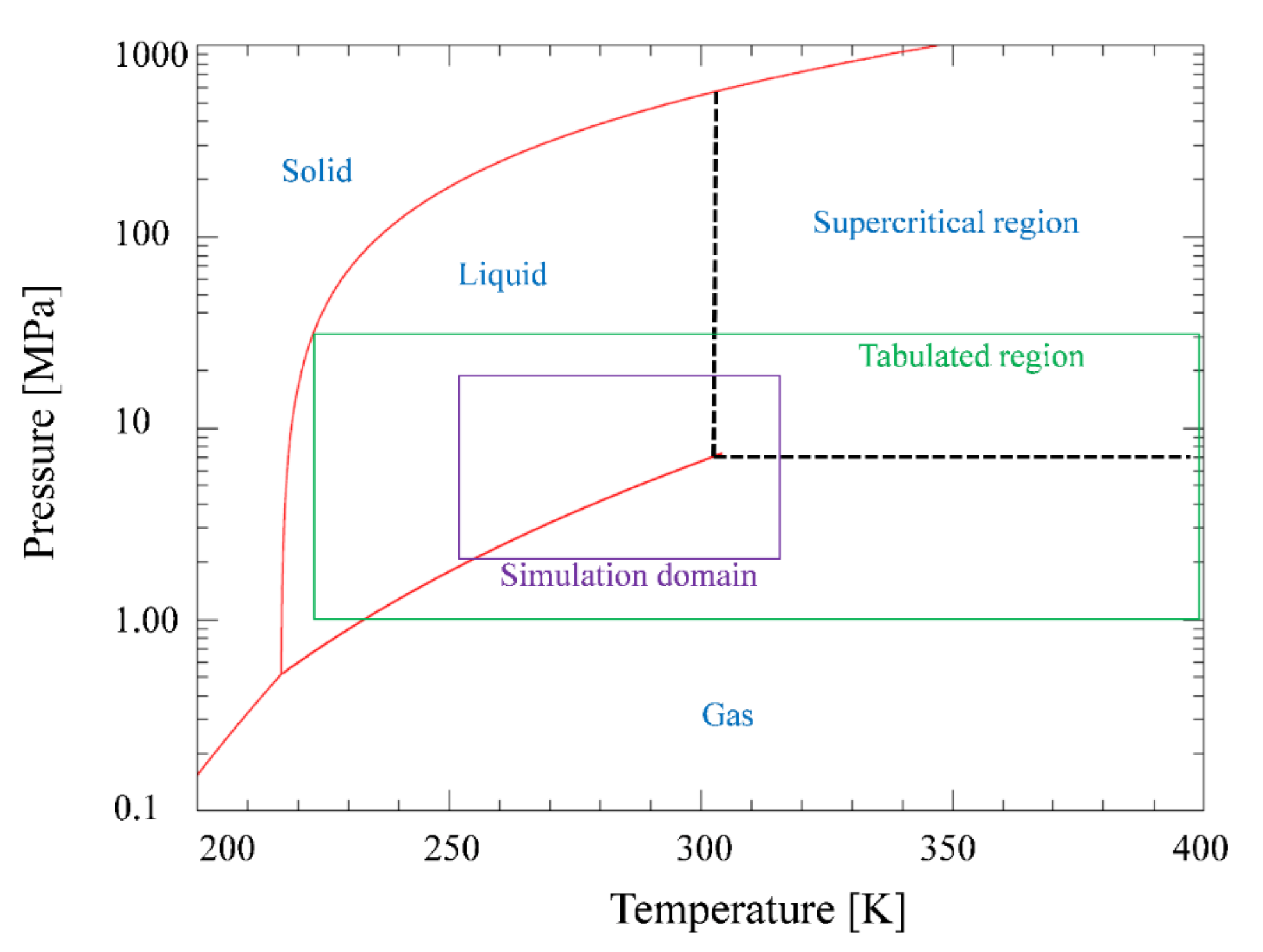
Figure 6 illustrates the tabulated region of CO2 in which the RGP table range for pressure is chosen from 1 to 20 MPa, and for temperature, 220 to 400 K is considered to cover all the simulation criteria.

Figure 6.
P-T diagram for CO2.
3.2. Turbulence Model
In this study, a 3-D numerical model of the Tesla turbine was developed using the shear stress transport turbulence model (SST), and the flow pattern in the Tesla turbine can be considered a steady state [32,33]. The SST turbulence model effectively applies the k-ε turbulence model and the k-ω turbulence model in the free stream and near the wall region, respectively.
The mass, momentum, and energy equations for compressible turbulence flow in the Tesla turbine are:
The turbulence kinetic energy (k) and specific turbulence dissipation (ω) of the SST model result from solving the following transport equations:
For further details regarding the coefficients in Equations (12) and (13), refer to [34].
3.3. Boundary Conditions
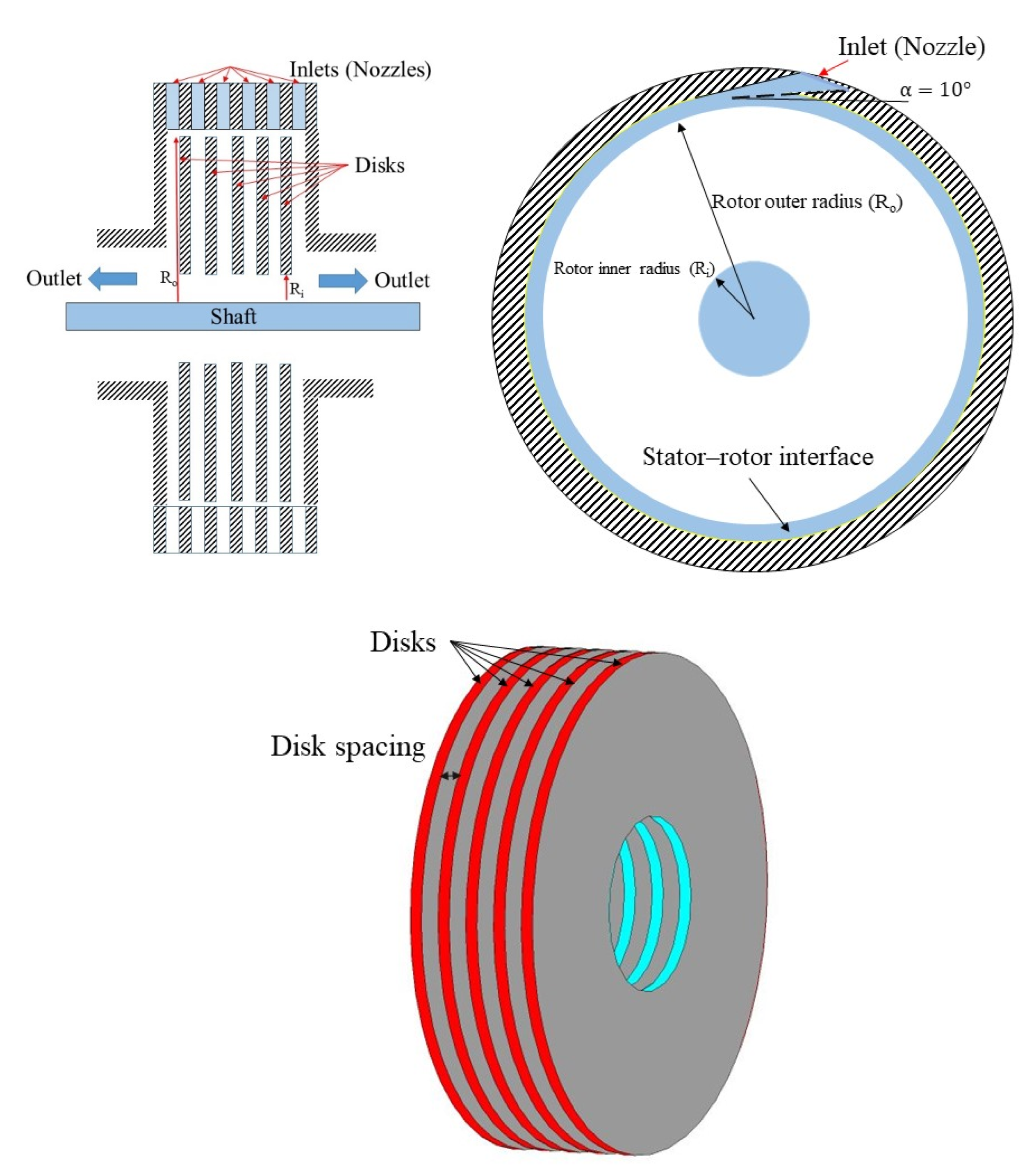
The geometry of the Tesla turbine is taken from a previous study [6] and is shown in Figure 7. In addition, the boundary conditions of the Tesla turbine are presented in Table 2 and the Tesla turbine geometry is presented in Table 3.
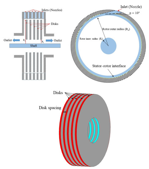
Figure 7.
Geometry of the Tesla turbine (stator and rotor).
Table 2.
Boundary conditions of the Tesla turbine.
Table 3.
Tesla turbine design dimensions [6].
The CFD validation and grid independence study were carried out in our previous study [6]. For the current study, 1.425 million hexahedral cells are constructed in the CFD.
4. Results and Discussion
The aim of this section is to investigate the effect of the Tesla turbine on the COP, transiting exergy efficiency, exergy losses, and exergy efficiency of the heat pump cycle integrated with the Tesla turbine. The effect of the disk spacing and rotor speed on the Tesla turbine parameters, which are torque and power, are investigated. In addition, the exergy loss and transiting exergy efficiency of the Tesla turbine are investigated. Finally, the effect of Tesla turbine disk spacing on the COP and exergy efficiency of the TeslaHPS is presented.
4.1. Effect of Rotor Speed and Disk Spacing on the Tesla Turbine Parameters
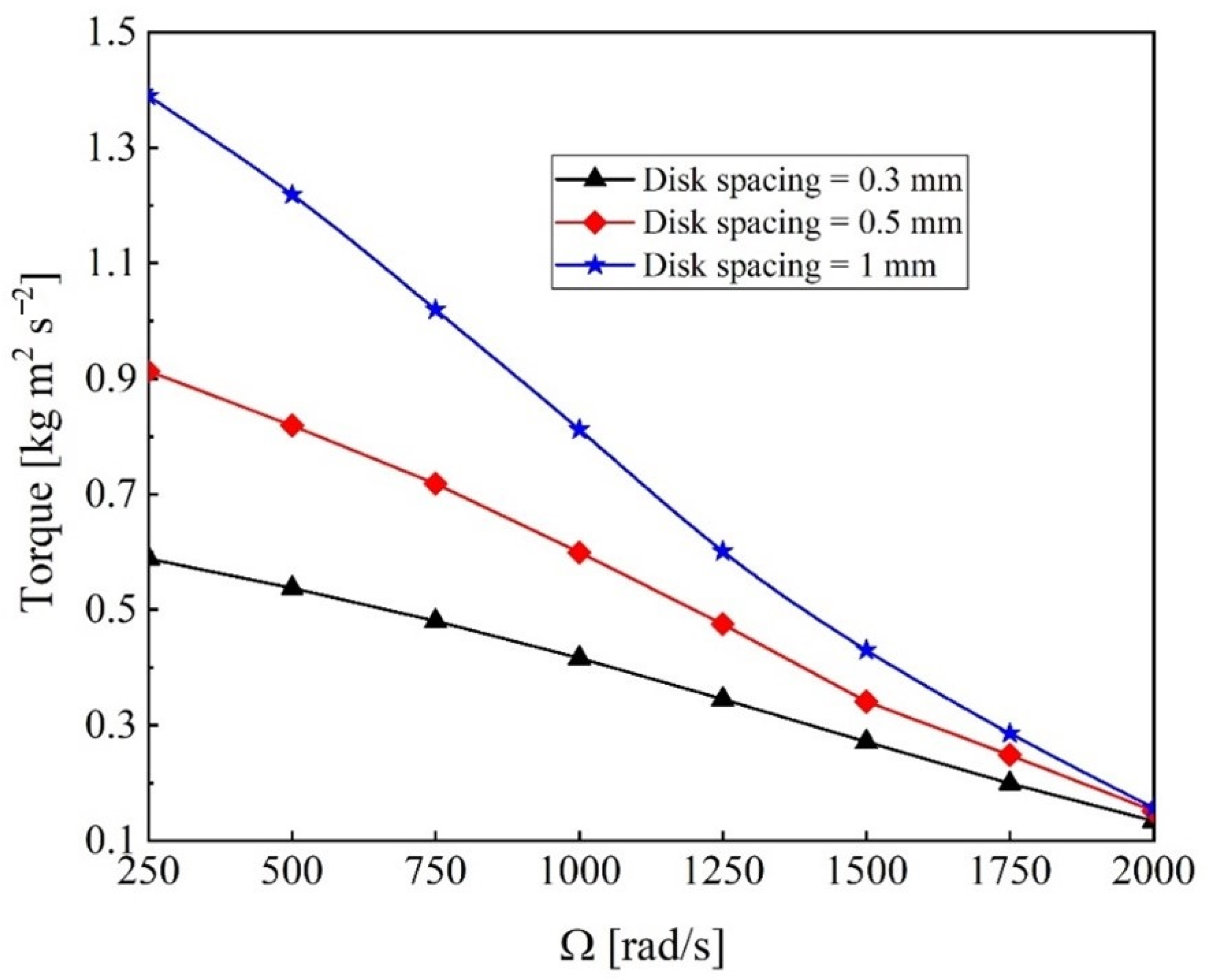
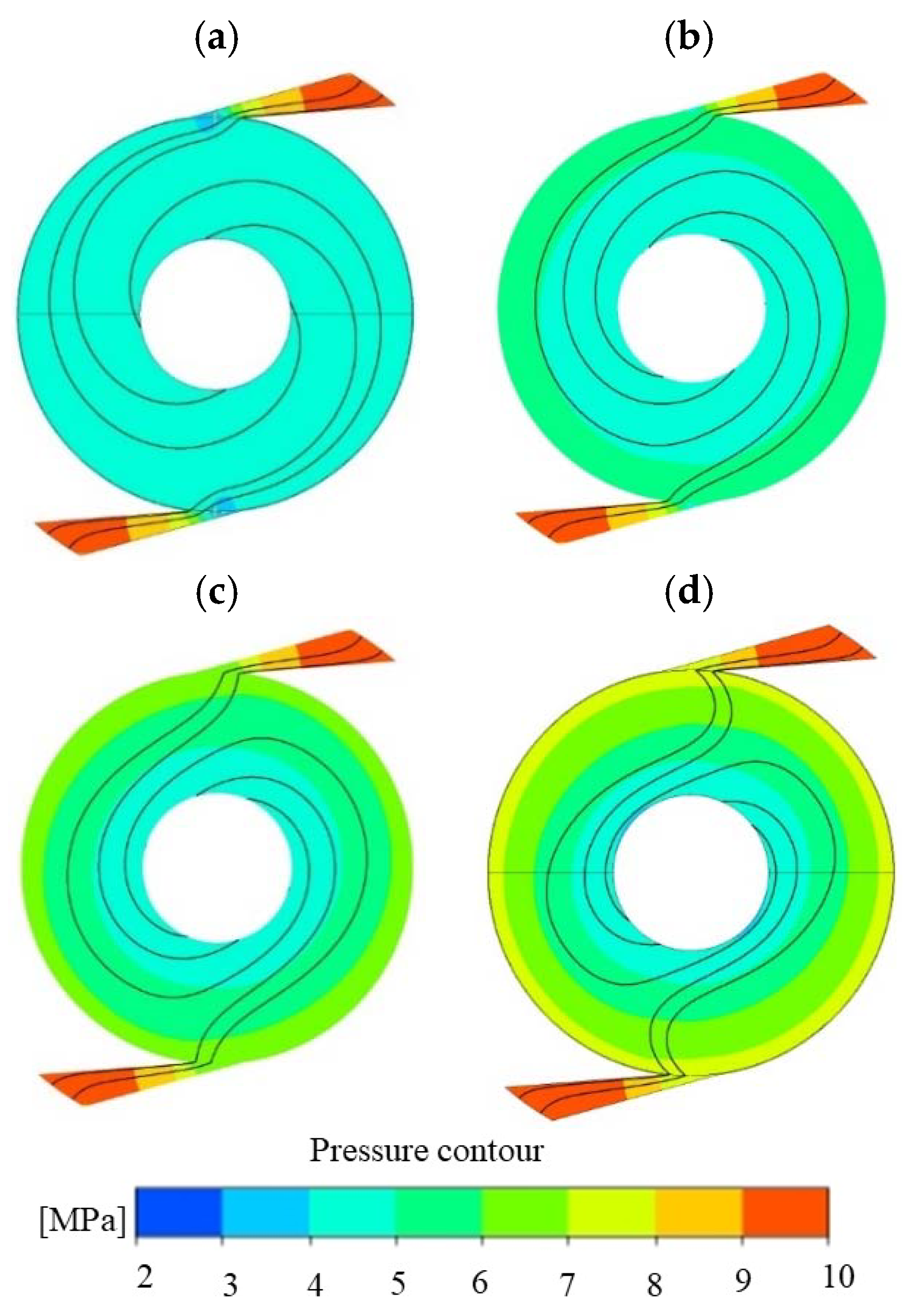
The torque production with respect to the disk spacing and rotor speed is presented in Figure 8. The mass flow increases in proportion to the disk spacing due to the increase in area, which leads to an increase in torque production at a constant rotor speed. A higher rotor speed leads to a lower torque on the rotor wall. For better understanding, the pressure contour and flow path at a constant disk spacing and different rotor speeds are presented in Figure 9. The working fluid pressure at the rotor inlet increases with increasing rotor speed from 250 to 2000 rad/s, which leads to a higher mass flow rate and then leads to a higher torque. Besides, the flow paths for the different rotor speeds show that the working fluid at a lower rotor speed produces higher tangential velocity and lower radial velocity, which causes higher centrifugal force and, consequently, higher torque.
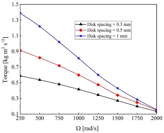
Figure 8.
Effect of disk spacing and rotor speed on the torque.

Figure 9.
Pressure contour and flow path at different rotor speeds: (a) 250, (b) 1000, (c) 1500, and (d) 2000 rad/s.
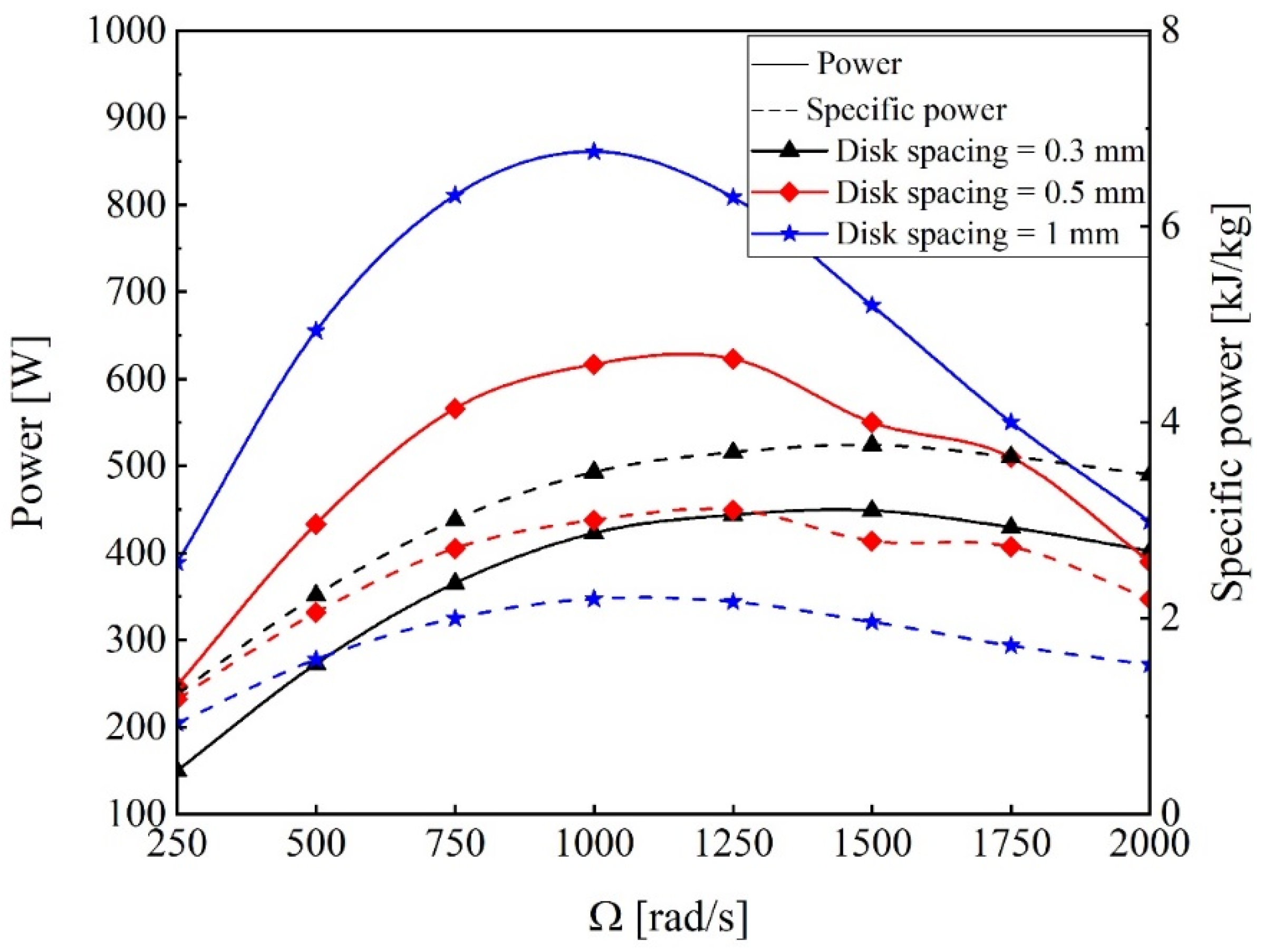
The power and specific power of the Tesla turbine are illustrated in Figure 10 with respect to the disk spacing and rotor speed. The power and specific power of the Tesla turbine are given as:

Figure 10.
Effect of disk spacing and rotor speed on the power and sp. power of the Tesla turbine.
The power of the Tesla turbine depends on the torque production and rotor speed, and as shown in Figure 10, increasing the rotor speed reduces the torque. Therefore, the turbine power increases until at optimum rotor speed and then decreases. The maximum power of the turbine at 1 mm disk spacing is 861 W, which occurs at 1000 rad/s. Increasing the rotor spacing produces more torque, so the turbine power at a constant rotor speed is higher. However, the specific power of the turbine is maximized at a lower disk spacing, which can be explained by the increase in the mass flow rate at a higher disk spacing. Therefore, increasing the mass flow rate overcomes the increasing turbine power, which leads to a decrease in specific power.
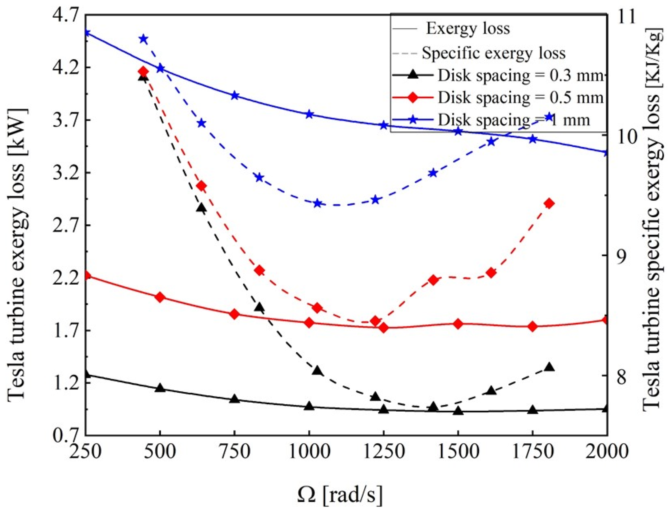
The effect of disk spacing and rotor speed with respect to the Tesla turbine exergy loss and specific exergy loss is presented in Figure 11. The exergy loss of the Tesla turbine depends on the inlet mass flow rate and specific exergy loss. The specific exergy loss of the Tesla turbine decreases until the optimum rotor speed and then increases due to the mutual effect of torque and rotor speed. In addition, increasing the disk space leads to increasing the mass flow rate, and increasing the mass flow rate has a direct effect on the exergy loss of the Tesla turbine. The minimum value of the exergy loss of the Tesla turbine occurs at a lower rotor speed with increased disk spacing. With the same inlet and outlet conditions (10 and 4 MPa), the specific exergy loss of the expansion valve equals 11.8 kJ/kg, and the maximum and minimum specific exergy losses of the Tesla turbine are 10.8 and 7.7 kJ/kg. Thus, it can be concluded that if the Tesla turbine performs under its ideal condition, the percentage of exergy loss can be reduced by up to 34.7%.
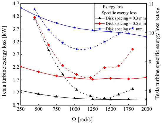
Figure 11.
Effect of disk spacing and rotor speed on the exergy loss of the Tesla turbine.
The effect of rotor speed and disk spacing on the transiting exergy efficiency and transiting exergy is illustrated in Figure 12. The transiting exergy efficiency of the Tesla turbine illustrates the same trend of specific power in which the transiting exergy efficiency increases until the optimum value of the rotor speed and then decreases. As the disk spacing decreases, the transiting exergy efficiency increases. The maximum transiting exergy efficiency, minimum turbine exergy loss, and maximum specific power occur at the same rotor speed, which means that transiting exergy efficiency is able to predict the optimum rotor speed corresponding to the maximum specific power. In addition, the Tesla turbine has a higher transiting exergy at a lower rotor speed and increasing the disk spacing leads to an increase in the transiting exergy.
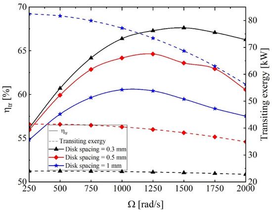
Figure 12.
Effect of rotor speed and disk spacing on the transiting exergy efficiency of the Tesla turbine.
Table 4 shows the exergy metrics of the Tesla turbine with respect to the rotor speed. It can be observed that the transiting exergy efficiency increases from 56.16% to 67.96% when increasing the rotor speed from 250 to 1500 rad/s and then decreases slowly to about 66.43% (about 2.25% of decrease) when rotor speed rises to 2000 rad/s. Since both consumed and produced exergies decrease by increasing the rotor speed, the reduction in exergy production is surpassed by the reduction in exergy consumption, which causes the augmentation of the transiting exergy efficiency until reaching the optimum rotor speed (1500 rad/s). Furthermore, the reduction of the exergy consumption overcomes the reduction of the exergy production, which leads to decreasing the transiting exergy efficiency. The results also show a minimum value for the exergy loss, and maximum values of the transiting exergy efficiency and Grassmann exergy efficiency occur at the same rotor speed.
Table 4.
Variation in exergy metrics with respect to the rotor speed for the Tesla turbine at disk spacing = 0.3 mm.
4.2. Effect of the Tesla Turbine on the Transcritical Heat Pump System
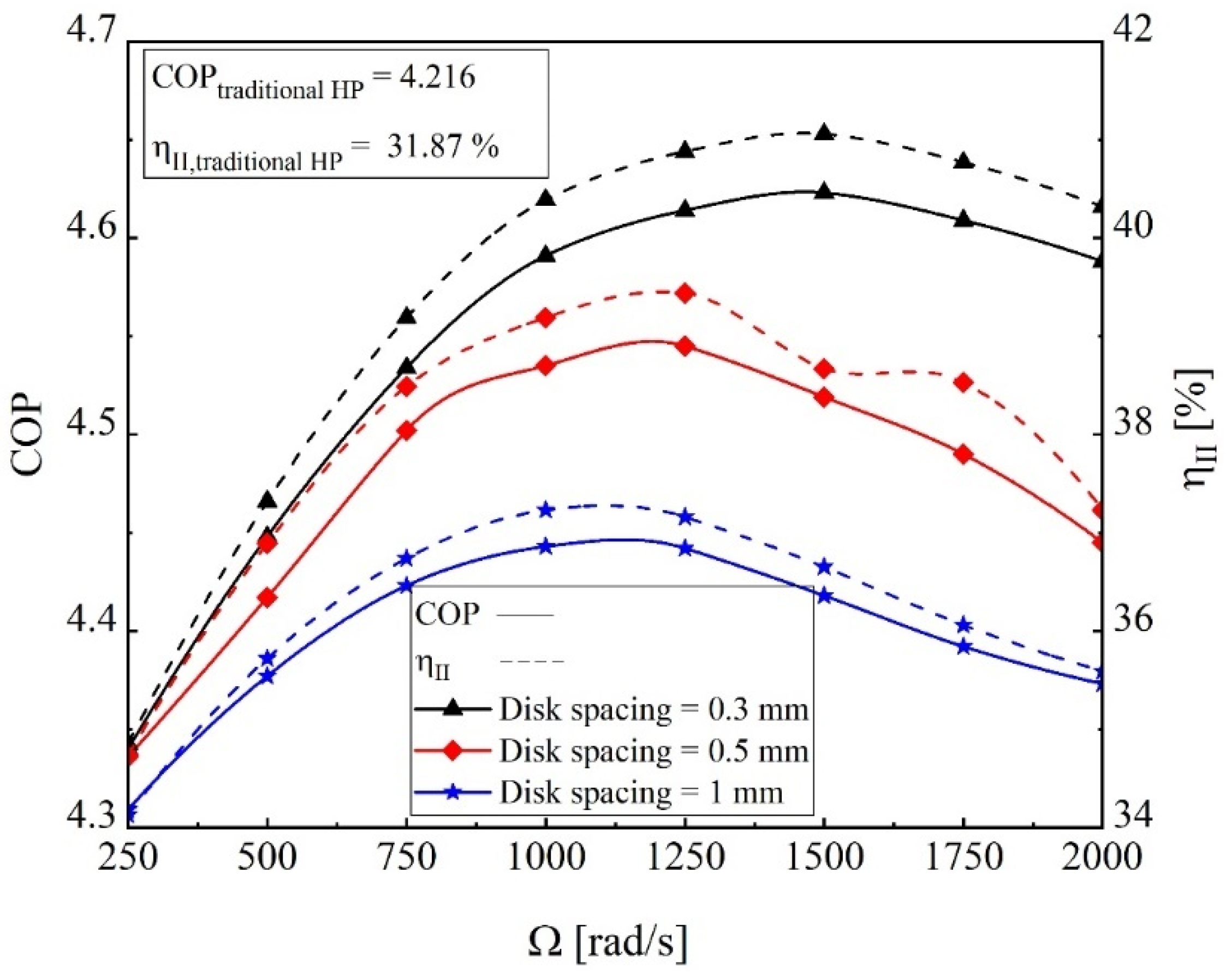
The effect of rotor speed and disk spacing on the COP and exergy efficiency of the heat pump system integrated with the Tesla turbine is indicated in Figure 13. The gas cooler and compressor inlet and outlet conditions are constant, so the power of the Tesla turbine is the only effective parameter on the COP. The COP of the TeslaHPS at a constant disk spacing reaches the maximum value at an optimum rotor speed and then decreases by increasing the rotor speed. In addition, increasing the disk spacing leads to increasing the specific power, and consequently, the COP of the TeslaHPS increases (Figure 10). From Figure 13, it is observed that exergy efficiency indicates a similar increase with respect to disk spacing. Comparing COP and exergy efficiency between the TeslaHPS and traditional HPS, it can be concluded that by employing the Tesla turbine as an expansion valve, the COP and exergy efficiency improvements are up to 9.8% and 28.9%.

Figure 13.
The effect of rotor speed and disk spacing on the COP of the heat pump system integrated with the Tesla turbine.
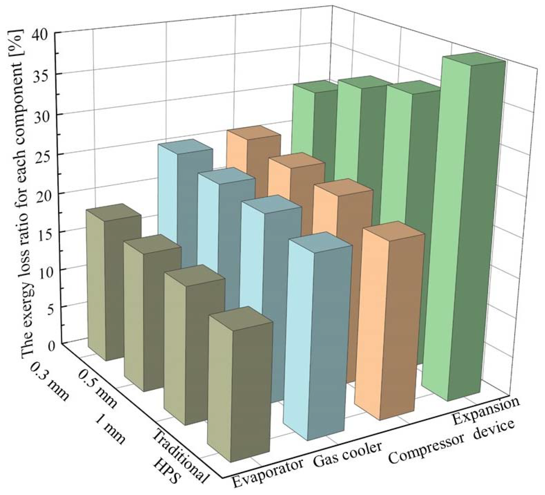
The exergy loss of each component is illustrated in Figure 14 in various heat pump systems integrated with an expansion device, namely, Tesla turbine with 0.3, 0.5, and 1 mm disk spacing and expansion valve. The exergy loss ratio for other components in the various heat pump configurations is close to each other, and for the traditional HPS, the exergy loss ratio in the evaporator, gas cooler, and compressor is lower than for the TeslaHPS because the highest exergy loss ratio is assigned to the expansion valve. Consequently, other components in the traditional HPS have a lower exergy loss ratio than in the TeslaHPS.
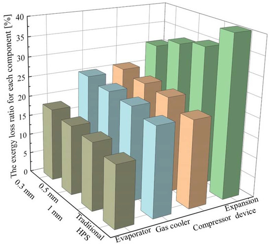
Figure 14.
Exergy loss ratio of each component.
5. Conclusions
In the present study, the numerical simulation of the Tesla turbine with CO2 as a working fluid was analyzed using the RGP table at different rotor speeds and three different disk spacings in the commercial ANSYS CFX solver. The CFD simulation showed that at a higher disk spacing, the Tesla turbine power production is higher; however, the specific power has the opposite trend. The tesla turbine produces more torque at a higher disk spacing due to a higher mass flow rate. The maximum value of turbine transiting exergy efficiency, as a function of rotor angular velocity, provides the maximum value of COP for the TeslaHPS. In addition, by integrating the Tesla turbine, the COP and exergy efficiencies of the heat pump system rise to 9.8% and 28.9%, respectively. In addition, the Tesla turbine can recover up to 34.7% of the expansion valve exergy loss. The Tesla turbine can recover approximately 14% to 20% of the compressor work and can be connected to the shaft. The added value of the Tesla turbine is to produce mechanical work, which will reduce the quantity of the required one for the compressor. The intervention of the turbine allows an increase in the coefficient of performance of the heat pump. Certainly, the amount of work generated by this turbine is not enough to power a generator or a pump for other things, but this work is fed back into the system. Moreover, the important objective is to reduce the exergy losses observed in the absence of the Tesla turbine in the system.
Author Contributions
This paper is the result of the work of all the authors. A.A. is the principal investigator who developed the conceptualization and the model of the Tesla heat pump system. M.S. proposed the methodology of transiting exergy and provided guidance and technical assistance. M.K. provided editing and thermodynamics review as scientific and technical assistance. All authors contributed to the discussion of the results. All authors have read and agreed to the published version of the manuscript.
Funding
This project is a part of the Collaborative Research and Development (CRD) Grants Program at “Université de Sherbrooke”. The authors acknowledge the support of the Natural Sciences and Engineering Research Council of Canada, Hydro-Québec, Rio Tinto, Alcan, and Canmet ENERGY Research Center of Natural Resources Canada (RDCPJ451917-13). The authors acknowledge too the support of the New Brunswick Innovation Foundation (NBIF) (RIF2018-025) and the Faculté des Études Supérieures et de la Recherche (FESR) of the Université de Moncton.
Data Availability Statement
Not applicable.
Conflicts of Interest
The authors declare no conflict of interest.
Abbreviations
The following abbreviations are used in this manuscript:
| Nomenclature | |
| C | specific power, kJ kg−1 |
| ex | specific exergy, kJ kg−1 |
| exergy rate, kW | |
| h | specific enthalpy, kJ kg−1 |
| H | enthalpy, kW |
| exergy loss, kW | |
| k | turbulence kinetic energy, m2 s−2 |
| mass flow rate, kg s−1 | |
| pressure, MPa | |
| heating load, W | |
| s | specific entropy, kJ kg−1 K−1 |
| t | time, s |
| temperature, °C or K | |
| fluid velocity component in xi-direction, m s−1 | |
| power, W | |
| coordinates | |
| Greek symbols | |
| v | specific volume, m3 kg−1 |
| efficiency | |
| density, kg m−3 | |
| dynamic viscosity, kg m−1 s−1 | |
| rotor angular velocity, rad s−1 | |
| stress tensor, N m−2 | |
| torque, N m | |
| specific dissipation | |
| Subscripts | |
| C | compressor |
| E | evaporator |
| Ed | expansion device |
| Ev | expansion valve |
| Ext | external |
| in | inlet |
| Gc | gas cooler |
| Gr | Grassmann |
| i, j, k | Cartesian indices |
| out | out |
| sat | saturated |
| T | turbine |
| tr | transiting |
| Acronyms | |
| COP | coefficient of performance |
| EoS | equation of state |
| HEM | homogeneous equilibrium |
| HPS | heat pump system |
References
- Zhao, J.; Ning, J. Performance Analysis on CO2 Heat Pump Cycle with a Vortex Tube. In Proceedings of the 3rd International Conference on Smart Materials and Nanotechnology in Engineering, Antalya, Turkey, 20–21 April 2016. [Google Scholar]
- Bai, T.; Yan, G.; Yu, J. Thermodynamic assessment of a condenser outlet split ejector-based high temperature heat pump cycle using various low GWP refrigerants. Energy 2019, 179, 850–862. [Google Scholar] [CrossRef]
- Rashidi, M.M.; Aghagoli, A.; Raoofi, R. Thermodynamic analysis of the ejector refrigeration cycle using the artificial neural network. Energy 2017, 129, 201–215. [Google Scholar] [CrossRef]
- Sarkar, J. Cycle parameter optimization of vortex tube expansion transcritical CO2 system. Int. J. Therm. Sci. 2009, 48, 1823–1828. [Google Scholar] [CrossRef]
- Aghagoli, A.; Sorin, M.; Poncet, S. Thermodynamics analysis of a novel transcritical CO2 vortex tube heat pump cycle. In Proceedings of the 27th CANCAM; 2019; p. 4. [Google Scholar]
- Aghagoli, A.; Sorin, M. CFD modelling and exergy analysis of a heat pump cycle with Tesla Turbine using CO2 as a working fluid. Appl. Therm. Eng. 2020, 178, 115587. [Google Scholar] [CrossRef]
- Elbel, S.; Hrnjak, P. Experimental validation of a prototype ejector designed to reduce throttling losses encountered in transcritical R744 system operation. Int. J. Refrig. 2008, 31, 411–422. [Google Scholar] [CrossRef]
- Taslimi Taleghani, S.; Sorin, M.; Poncet, S. Analysis and Optimization of Exergy Flows inside a Transcritical CO2 Ejector for Refrigeration, Air Conditioning and Heat Pump Cycles. Energies 2019, 12, 1686. [Google Scholar] [CrossRef] [Green Version]
- Ersoy, H.K.; Bilir, N. Performance characteristics of ejector expander transcritical CO2 refrigeration cycle. Proc. Inst. Mech. Eng. Part A J. Power Energy 2012, 226, 623–635. [Google Scholar] [CrossRef]
- Taslimi Taleghani, S.; Sorin, M.; Poncet, S. Modeling of two-phase transcritical CO2 ejectors for on-design and off-design conditions. Int. J. Refrig. 2018, 87, 91–105. [Google Scholar] [CrossRef]
- Fangtian, S.; Yitai, M. Thermodynamic analysis of transcritical CO2 refrigeration cycle with an ejector. Appl. Therm. Eng. 2011, 31, 1184–1189. [Google Scholar] [CrossRef]
- Xing, M.; Yu, J.; Liu, X. Thermodynamic analysis on a two-stage transcritical CO2 heat pump cycle with double ejectors. Energy Convers. Manag. 2014, 88, 677–683. [Google Scholar] [CrossRef]
- Taslimi Taleghani, S.; Sorin, M.; Poncet, S.; Nesreddine, H. Performance investigation of a two-phase transcritical CO2 ejector heat pump system. Energy Convers. Manag. 2019, 185, 442–454. [Google Scholar] [CrossRef]
- Austin, B.T.; Sumathy, K. Transcritical carbon dioxide heat pump systems: A review. Renew. Sustain. Energy Rev. 2011, 15, 4013–4029. [Google Scholar] [CrossRef]
- Croquer, S. Combined CFD and Thermodynamic Analysis of a Supersonic Ejector with Liquid Droplets. Ph.D. Thesis, Université de Sherbrooke, Sherbrooke, QC, Canada, 2018. [Google Scholar]
- Gutak, A.D. Experimental investigation and industrial application of Ranque-Hilsch vortex tube. Int. J. Refrig. 2015, 49, 93–98. [Google Scholar] [CrossRef]
- Rafiee, S.E.; Sadeghiazad, M.M. Three-dimensional and experimental investigation on the effect of cone length of throttle valve on thermal performance of a vortex tube using k-ε turbulence model. Appl. Therm. Eng. 2014, 66, 65–74. [Google Scholar] [CrossRef]
- Thakare, H.R.; Parekh, A.D. Experimental investigation & CFD analysis of Ranque–Hilsch vortex tube. Energy 2017, 133, 84–298. [Google Scholar] [CrossRef]
- Rafiee, S.E.; Sadeghiazad, M.M. Experimental and 3D CFD investigation on heat transfer and energy separation inside a counter flow vortex tube using different shapes of hot control valves. Appl. Therm. Eng. 2017, 110, 648–664. [Google Scholar] [CrossRef]
- Aghagoli, A.; Sorin, M. Thermodynamic performance of a CO2 vortex tube based on 3D CFD flow analysis Performance. Int. J. Refrig. 2019, 108, 124–137. [Google Scholar] [CrossRef]
- Matveev, K.I.; Leachman, J. Numerical investigation of vortex tubes with extended vortex chambers. Int. J. Refrig. 2019, 108, 145–153. [Google Scholar] [CrossRef]
- Zangana, L.M.; Barwari, R.R.I. The effect of convergent-divergent tube on the cooling capacity of vortex tube: An experimental and numerical study. Alexandria Eng. J. 2020, 59, 239–246. [Google Scholar] [CrossRef]
- Groll, E.A.; Kim, J. Review Article: Review of Recent Advances toward Transcritical CO2 Cycle Technology. HVAC&R Res. 2007, 13, 499–520. [Google Scholar] [CrossRef]
- Yingfu, L.; Chunjing, G.; Guangya, J. Vortex Tube Expansion Transcritical CO2 Heat Pump Cycle. Appl. Mech. Mater. 2012, 190–191, 1340–1344. [Google Scholar] [CrossRef]
- Collins, R.L.; Lovelace, R.B. Experimental Study of Two-Phase Propane Expanded through the Ranque-Hilsch Tube. Trans. ASME 1979, 101, 300–305. [Google Scholar] [CrossRef]
- Takahama, H.; Kawamuras, H.; Katos, S.; Yokosawa, H. Performance characteristics of energy separation in a steam-operated vortex tube. Int. J. Eng. Sci. 1979, 17, 735–744. [Google Scholar] [CrossRef]
- Rice, W. Tesla Turbomachinery. In Proceedings of the IV International Nikola Tesla Symposium, Belgrade, Serbia, 23–25 September 1991. [Google Scholar]
- Shi, Y.; Yoonessi, M.; Weiss, R.A. High Temperature Shape Memory Polymers. Macromolecules 2013, 46, 4160–4167. [Google Scholar] [CrossRef]
- Traum, M.J.; Weiss, H.L. Tiny Tesla Turbine Analytical Performance Validation Via Dynamic Dynamometry. E3S Web Conf. 2019, 113, 03024. [Google Scholar] [CrossRef] [Green Version]
- Yang, J.L.; Ma, Y.T.; Li, M.X.; Guan, H.Q. Exergy analysis of transcritical carbon dioxide refrigeration cycle with an expander. Energy 2005, 30, 1162–1175. [Google Scholar] [CrossRef]
- Sorin, M.; Khennich, M. Exergy Flows Inside Expansion and Compression Devices Operating below and across Ambient Temperature. In Energy Systems and Environment; InTech: Houston, TX, USA, 2018. [Google Scholar] [CrossRef] [Green Version]
- Qi, W.; Deng, Q.; Chi, Z.; Hu, L.; Yuan, Q.; Feng, Z. Influence of Disc Tip Geometry on the Aerodynamic Performance and Flow Characteristics of Multichannel Tesla Turbines. Energies 2019, 12, 572. [Google Scholar] [CrossRef] [Green Version]
- Qi, W.; Deng, Q.; Jiang, Y.; Yuan, Q.; Feng, Z. Disc Thickness and Spacing Distance Impacts on Flow Characteristics of Multichannel Tesla Turbines. Energies 2019, 12, 44. [Google Scholar] [CrossRef] [Green Version]
- Menter, F.R. Two-Equation Eddy-Viscosity Turbulence Models for Engineering Applications. AIAA J. 1994, 32, 1598–1605. [Google Scholar] [CrossRef] [Green Version]

Publisher’s Note: MDPI stays neutral with regard to jurisdictional claims in published maps and institutional affiliations. |
© 2022 by the authors. Licensee MDPI, Basel, Switzerland. This article is an open access article distributed under the terms and conditions of the Creative Commons Attribution (CC BY) license (https://creativecommons.org/licenses/by/4.0/).