Article

Closing of Carbon Cycle by Waste Gasification for Circular Economy Implementation in Poland

1
Institute for Chemical Processing of Coal, ul. Zamkowa 1, 41-803 Zabrze, Poland
2
Department of Thermal and Fluid Flow Machines, Faculty of Energy and Fuels, AGH University of Science and Technology, al. Mickiewicza 30, 30-059 Krakow, Poland
*
Author to whom correspondence should be addressed.
Energies 2022, 15(14), 4983; https://doi.org/10.3390/en15144983
Submission received: 29 April 2022 / Revised: 23 June 2022 / Accepted: 24 June 2022 / Published: 7 July 2022
(This article belongs to the Special Issue Sustainable Management of Waste for Renewable Energy Resources)

Abstract

:
Domestic coal and waste resources, which are valuable sources of carbon, can support efforts to transform a linear economy into a circular carbon economy. Their use, as an alternative to conventional, imported fossil resources (crude oil, natural gas) for chemical production, provides an opportunity for Poland to solve problems related to competitiveness, security of supply, and sustainable development in various industries. This is important for Poland because it can provide it with a long-term perspective of economic growth and development, taking into account global trends (e.g., the Paris Agreement) and EU legislation. The article presents a concept to support the transformation from linear toward a circular carbon economy under Polish conditions. The carried-out analyses showed that coal, RDF, and plastic waste fuels can be a valuable source of raw material for the development of the chemical industry in Poland. Due to the assumed availability of plastic waste and the loss of carbon in the production process, coal consumption is estimated at 10 million t/yr, both in the medium- and long-term. In case where coal consumption is reduced and an additional source of ‘green hydrogen’ is used, CO2 emissions could be reduced even by 98% by 2050. The presented results show the technical and economic feasibility of the proposed solution and could be the basis for development of the roadmap for transition of the linear to circular economy under Polish condition.

1. Introduction

Population growth, as well as rapid urbanization and industrialization are leading the global economy to face major challenges such as rising energy demand, huge amounts of waste generation, and environmental deterioration. Among others, the need to address waste management issues is cited as critical to achieving sustainable development [1].
The international community’s growing concern about environmental pollution associated with the accumulation of waste, including plastics, have led researchers, practitioners, and policy makers to seek alternatives to the dominant linear economic model of production and consumption. Over the past few years, basic and industrial research and development work has been intensified, targeting the possibilities of shifting various industrial sectors from a linear economy to a circular economy [2]. This is shown by the large number of publications in scientific journals that present the results of basic and developmental research [3,4,5,6,7], environmental [8,9], macroeconomic [10,11], social [12,13,14], and political analyses [15,16,17,18,19].
In a circular economy (CE), raw material resources are recovered. Solid and liquid waste is minimized and gas emissions along with energy losses are reduced by closing material and energy loops. In the case of waste management, the most commonly used strategies related to CE development include [20]: recycle, refurbish/remanufacture, reuse/redistribute, and maintain/prolong.
According to the waste management hierarchy recommended by the IPCC, in the first step waste should be avoided and reused, followed by recycling, energy recovery and landfilling [20,21].
The most commonly used strategy in CE is material recycling, with the scale varying across industries. Waste management, the electrical engineering industry, and construction have been quick to adopt CE principles, while mining, chemicals, and other sectors have a passive approach to it [20]. Another strategy, quite commonly used in CE is the reduction of waste through its thermal and biochemical conversion into energy. Municipal waste, agricultural residues, industrial and municipal sewage sludge can be processed by thermochemical methods (pyrolysis [22,23,24], incineration [25,26], gasification [27], and others [28,29,30]), biochemical methods (anaerobic digestion [31], aerobic composting [32], production of bioethanol [33], and biohydrogen [34,35]) along with pre-treatment technologies [36,37,38]. However, incineration of waste poses a threat to the environment due to the release of toxic gases and heavy metals as well as CO2, responsible for global warming, during this process.
Of the four technologies (incineration, pyrolysis, gasification, and anaerobic digestion), the first and the latter are considered the least and the most environmentally friendly waste-to-energy technologies respectively. Gasification, pyrolysis, and anaerobic digestion were found to be 33%, 65%, and 111% more environmentally friendly technologies for generating energy from waste than incineration [1].
Plastics waste is a particularly serious waste management problem. This is due to the scale of production and a small percentage of them subjected to recycling [21,39]. It is estimated that only 14% of generated plastic waste in the world is recycled [17,21]. Only 2% of the plastics waste generated is converted into products of similar quality, 8% is recycled into low value products, and 4% is lost in the process [17,21]. The rest is landfilled (60%) and incinerated (25%). Incineration aims primarily at avoiding landfilling or reducing the amount of plastics waste that cannot be mechanically recycled, while heat and in some cases electricity are produced as by-products. The process produces high CO2 emissions, and if the by-products cannot be used rationally, its energy efficiency is very low [21].
Intensification of the process of using plastic waste in a closed cycle requires the development of technology which can process any type of raw material (sorted and unsorted plastic waste) and make it possible to produce products of the same quality as the original ones [21]. This can be achieved by using the so-called thermochemical recycling [21,28,40], which theoretically allows the possibility to recycle any plastic and can be applied in any part of the world, regardless of the availability of advanced waste sorting systems [21].
Among the technologies that can be used in the thermochemical recycling process, only gasification has now reached the state of commercial development [24,28]. This includes dedicated systems for waste gasification [28] as well as coal technologies [41].
The use of the gasification process and then chemical synthesis to recreate the entire stream of recycled plastics requires an additional source of carbon element, e.g., in the form of fossil fuels [42]. This is due to the losses of the carbon element in the form of CO2, resulting from the need to obtain the appropriate gas composition required at the stage of chemical synthesis. Minimizing the loss of carbon, and consequently CO2 emissions, can be achieved by feeding the system with an appropriate amount of ‘green hydrogen’, produced using renewable energy sources. However, given the scale of production required, this is a technically feasible option in the medium-term.
At the beginning of the chain of a linear carbon economy are the mining of coal and the import of oil and natural gas. At the end of the chain, carbon, contained in chemical products or energy carriers, is burned in power plants, internal combustion engines and waste incinerators and released into the atmosphere as CO2. While the energy industry is gradually switching to coal-free energy sources, i.e., renewable electricity, e-hydrogen, the chemical industry still relies on coal to supplement its demand in alternative sources [2].
Full decarburization of global industry is essential to achieve climate stabilization, and achieving net zero GHG emissions between 2050 and 2070 is necessary to limit global warming to 2 °C. With the adoption of the Paris Agreement many countries will need to adopt more stringent measures to achieve their respective greenhouse gas (GHG) mitigation targets required [43]. Achieving zero net emissions from industry and economy in this time frame is possible through the implementation of technologies with high energy efficiency, ensuring CO2 capture, production of energy from renewable sources, and implementation of the technology of obtaining ‘green hydrogen’ as a raw material for the energy and chemical industry [44].
The circular economy is the key to structural change in Central European coal regions such as Poland. Such an economic model must become operational on an industrial scale by 2030 at the latest, in order to provide coal-related regions with a sustainable development perspective. Although the transition to a circular economy requires some degree of policy intervention, it nevertheless brings tangible macroeconomic and social benefits, as well as significant environmental benefits [45].
The analysis presented in this paper concerns whether the circular carbon economy is in principle feasible in the period up to 2050 from the point of view of the availability of alternative carbon sources in terms of quantity and quality, what technical conditions need to be created and what is the sustainability assessment. The central scenario is synthesis chemistry for the circular production of light olefins (ethylene and propylene) via an intermediate methanol synthesis step. This represents an alternative to the current petrochemical production of olefins in steam cracking. In other words, the aim is to evaluate transformation scenarios to bring chemical recycling of alternative carbon sources to industrial scale.

2. Materials and Methods

The concept of circular carbon economy assumes the use of waste and coal co-gasification technology for the production of syngas as a raw material for the chemical and power industries (Figure 1).
Recovered waste, including in particular waste plastics, is a valuable raw material in the gasification process. The produced synthesis gas is used to produce chemicals necessary for the functioning of the economy. For the purposes of this paper (study), the production of polyolefins through methanol (MtO: Methanol to Olefins) was adopted. In order to obtain the required level of production, additional coal must be supplied to the system. The amount of required coal depends on the level of raw material recycling of waste. In addition, hydrogen produced from renewable sources can be fed into the cycle. In this case, it is possible to reduce the CO2 emissions accompanying the production process to almost zero. The base technology—the central one, coupling the entire system—is the technology of gasification of solid fuels, including waste fuels.
Six scenarios of gradual transition to a circular carbon economy were analyzed:
  • Reference scenario 2030 time horizon—Case 1: production of olefins from natural gas (linear economy, no thermochemical recycling of waste);
  • Reference scenario 2030 time horizon—Case 2: production of olefins from coal (linear economy, no thermochemical recycling of waste);
  • Circular carbon economy, time horizon 2030—Case 3: olefins are produced on the basis of RDF waste and coal without ‘green hydrogen’ and the production volume covers the market demand (no production from oil). According to the adopted scenario, it is assumed that in 2030 part of the waste plastics is disposed of in cement plants and incinerators and only the unused surplus is directed to gasification;
  • Circular carbon economy, time horizon 2050—Case 4: olefins are produced from RDF waste and coal without ‘green hydrogen’ and the production volume covers the market demand. In this scenario, the amount of waste plastics available increases due to the increase in waste and the reduction in use for energy production (incinerators) and in the cement industry;
  • Circular carbon economy, time horizon 2050—Case 5: olefins are produced from RDF waste and coal with ‘green hydrogen’ and production volumes covers market demand;
  • Circular carbon economy, time horizon 2050—Case 6: olefins are produced from RDF waste and natural gas with ‘green hydrogen’ and the production volume covers market demand.
For each of the defined cases, process calculations and detailed material balances were carried out and used to determine the distribution of carbon in the system, determining direct and indirect CO2 emissions, and determining the demand for hard coal to balance the raw material needs, so as to obtain the volume of the assumed olefins production.
Additionally, for each case the total capital investments and olefins production costs were estimated.
For each of defined cases process calculations and material balances were carried out and used to determine the following:
  • Distribution of carbon element in the system;
  • Direct and indirect CO2 emissions;
  • Demand for hard coal to balance the raw material requirements.

2.1. Process Model of Olefins Production

The technological configuration of the olefins production system using solid fuels and natural gas is presented in Figure 2.
In the case of solid fuel gasification (Figure 2a), waste plastics and/or coal are fed into the gasification system. The raw process gas produced is cooled and pre-treated, and then directed to the CO conversion unit. In this unit, the conversion of CO to H2 and CO2 takes place and, as a consequence, a gas is produced with the composition required for the synthesis of methanol. After further cooling, removal of sulphur compounds and CO2, the gas is fed to a methanol synthesis unit. The methanol produced goes to the olefins synthesis system (MtO). The CO2 removed from the gas is one of the main sources of emissions, which significantly burden the manufactured product. In the long-term, the use of ‘green hydrogen’ in the process can reduce these emissions practically completely. Desulphurized natural gas (not presented in the diagram) is fed to the gas conversion unit/system (Figure 2b). The conversion system produces synthesis gas with the composition required by the methanol synthesis system/unit (there is no need to use a CO conversion unit). Other elements of the installation are analogous to the technological configuration of the system using solid fuels. For natural gas cases, the main sources of CO2 emissions are the combustion of off-gases and emissions accompanying the energy recycling of plastics waste (Case 1).

2.1.1. Solid Fuel Gasification System

The basic reasons for the selection of the gasification technology were the high efficiency of the process and the form of generated solid waste, which ensures the minimization of their harmful impact on the environment. The fuel gasification island was developed based on Institute for Chemical Processing of Coal (IChPW) data and literature data on gasification technology in a entrained reactor with a dry fuel feed, based on the Shell technology [46]. This reactor has a very high conversion rate of carbon element and high process efficiencies. An important advantage of the technology is the form of solid waste from the process. Due to the high gasification temperatures, the ash is removed from the system in a vitrified form that is not hazardous/harmful to the environment.
Shell technology is a commercial technology used to gasify solid fuels, including coal. In the case of RDF and plastics waste gasification, the technological challenge will be to develop the fuel preparation technology for the gasification process (entrained gasification technologies require grinding of the fuel to a grain size below 100 μm).
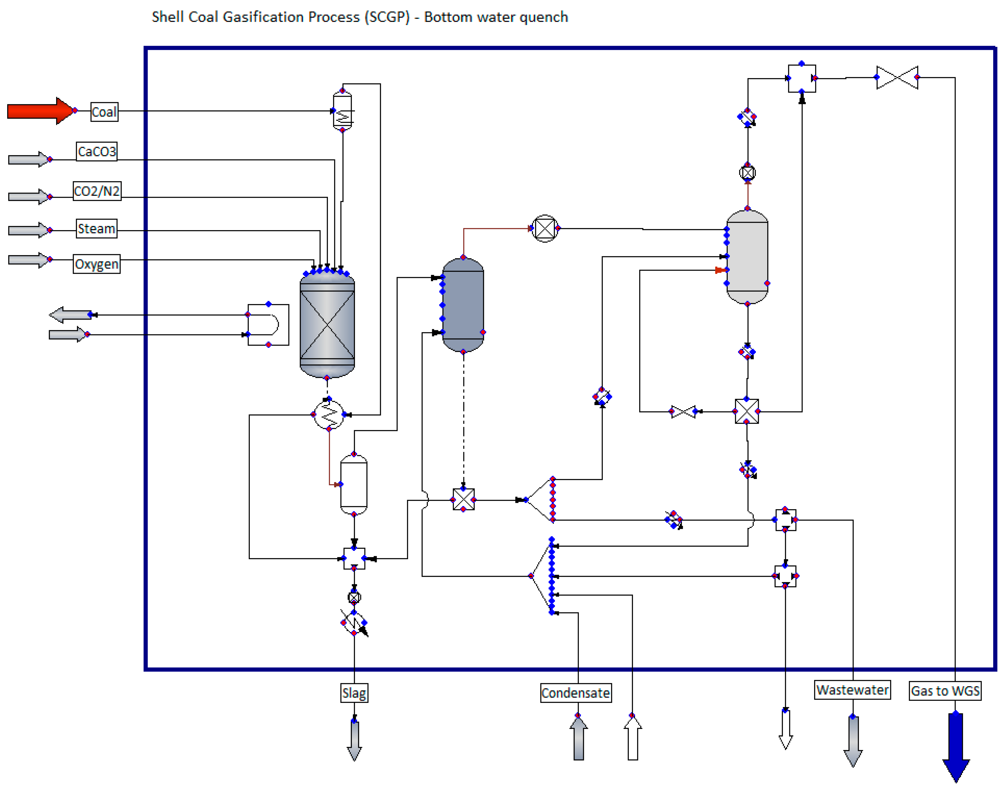
The calculations of the gasification system and process gas conversion were performed using the developed process model in the process simulator ChemCAD (Figure 3). The basic assumptions and calculation results for the gasification and process gas conversion system are presented in Table 1.

2.1.2. Conversion of Natural Gas

The natural gas conversion unit was developed using the indicator method based on literature data [46] based on Autothermal Reforming (ATR) technology. A mixture of natural gas, oxygen, and steam, produced by evaporating boiler water, is introduced into the reactor. The conversion process is carried out at 900–1050 °C and a pressure of 30–55 bar in the presence of a nickel catalyst. The basic consumption and production indicators for the natural gas conversion unit are presented in Table 2.

2.1.3. Methanol and Olefins Synthesis System

Methanol (Casale technology) and olefins synthesis units were developed by the index method based on IChPW and literature data [47,48].
In the case of methanol production, the synthesis gas generated in the gasification unit is compressed and heated, and then goes to the catalytic reactor operating on the catalyst CuO/ZnO/Al2O3 or other commercially available. The generated gas is cooled and then subjected to MeOH synthesis. The unreacted gas is recirculated to the methanol synthesis unit. Water-free methanol is obtained with a two column distillation train.
It was assumed that the MtO process will be used for the synthesis of olefins. A high-ethylene variant with an ethylene to propylene ratio of approx. 1.7 was adopted for the calculations [48]. Methanol from the MeOH synthesis unit is first heated, evaporated and superheated, then it goes to the MtO conversion reactor (process parameters—pressure: 1–3 barg and temperature: 415–510 °C) where, in the presence of a catalyst, it is converted to dimethyl ether (DME) and then to ethylene, propylene and butylene. The overall selectivity of coal to ethylene and propylene is about 75–80%. In order to achieve the gas quality parameters for the MtO process, it is necessary to carry out a multi-stage gas purification, including processes such as cooling and pre-treatment in Water Quench, absorption for the separation of DME and oxygenates, and caustic washing, drying and distillation. The result is two raw product streams—liquid and gas, which are directed to the fractionation system (including a deethanizer, a demethanizer, a C2-splitter, a depropanizer, and a C3-splitter and a debutanizer) and a caustic scrubber. The process produces light olefins: ethylene (99.8% purity) and propylene (99.6% purity). All separated combustible fractions from the purification process are collected and sent as a residual gas to the energy island, where they are burned in the boiler. The basic production indicators for methanol and olefins synthesis units are included in Table 3.

2.1.4. Hydrogen Production System

For the ‘green hydrogen’ production unit for the methanol synthesis, water electrolysis with the use of green energy for hydrogen production was adopted. During the electrolysis of water, the chemical bond between hydrogen and oxygen is broken in the solution forming hydrogen and oxygen gas. For the 2050 analysis, the PEM electrolyser was adopted as the reference technology, which is expected to achieve efficiencies of 86% and a lifetime of 75,000 h [49]. The use of ‘green hydrogen’ allows to optimize the H2/CO ratio in order to maximize the efficiency of the methanol synthesis unit without CO conversion. The energy consumption of 40 kWh/kg H2 was assumed for the calculations (for the year 2050).

2.2. Methodology of Calculating CO2 Emissions in the Analyzed Systems

In determining the emissions associated with the production process, direct and indirect emissions have been taken into account. Direct emission included emission related to the need to remove excess CO2 (to adjust gas composition for methanol synthesis) from the synthesis gas and from the combustion of the so-called off-gases (energy production for own needs). In addition, for the baseline scenario—linear economy (Case 1 and Case 2), the source of direct emissions was the energetic use of waste plastics (produced plastics, after use, instead of raw material recycling, are disposed of in waste incineration plants).
While determining the indirect emission, the emission associated with electricity consumption was taken into account. Indirect emissions were determined assuming the CO2 emission load for energy production at the level of 740 kg/MWh (emission factor for electricity generated in fuel combustion installations in Poland [50]).

2.3. Demand for Polymers

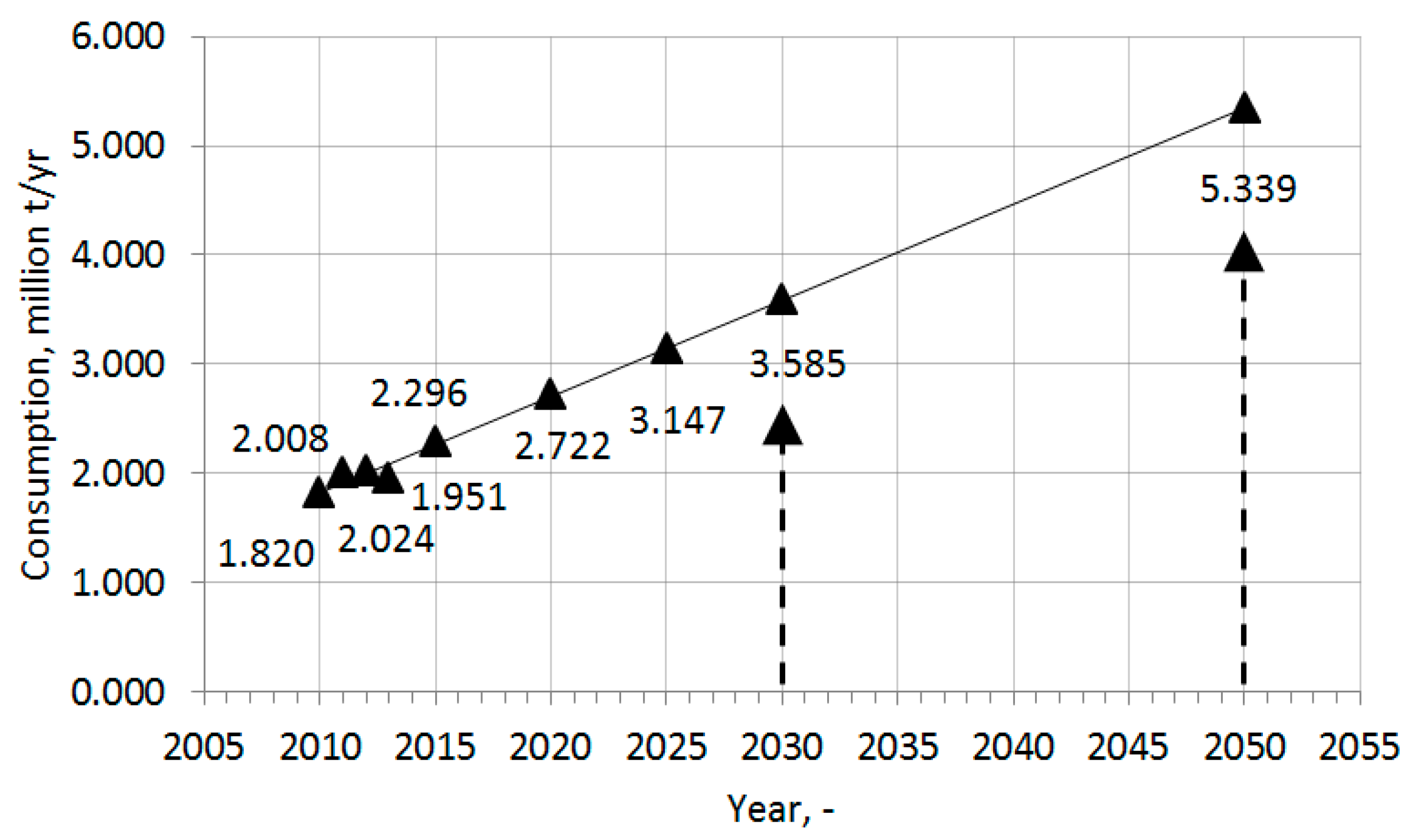
In terms of the demand for plastics, Poland ranks sixth (6.8% share) in Europe. The Polish plastics converting industry consumed approx. 3.13 million tonnes of various polymers in 2020. Plastics are used mainly in Poland in the packaging (35%), construction (24%), and automotive (10%) industries [29]. The demand for polymers in Poland has been estimated on the basis of data and growth forecasts according to the study “Forecasts of chemical industry production in Poland until 2020” [51]. Using the above data, polymer demand values for 2030 and 2050 were linearly extrapolated (Figure 4). For further calculations, polymer demand values for 2030 and 2050 were assumed to be 3.5 and 5.5 million t/yr, respectively.

2.4. Production of Municipal Waste in Poland

For the calculation of the projected amount of municipal waste in Poland, it was assumed that [52]
  • The production of municipal waste in 2020 is approx. 12.1 million tonnes, equivalent to 315 kg/person (assuming a population of 38.5 million);
  • The unit waste production in Poland will reach the current level in Germany (635 kg/person) in 2050;
  • The change in waste generation between 2020 and 2050 will be linear.
For the adopted trend, assuming a linear decrease in the number of inhabitants in Poland from 38.5 million in 2020 to 34 million in 2050 (data from the Central Statistical Office, Poland) [53], the total amount of municipal waste produced in Poland will be, respectively,
  • in 2030: 15.6 million tonnes;
  • in 2050: 21.6 million tonnes.
The linear model in this paper for estimating polymer demand and municipal waste production in Poland assumes economic development and thus an increased demand for polymers at least up to the level currently observed in Germany. It should be noted, however, that the model assumed is not the only option that could be chosen. For example, a different approach (non-linear) to estimating demand for polymers and municipal waste production could assume that demand for polymers will increase up to 2030, and then remain at that level or even decrease in the perspective up to 2050 as a result of the Green Deal introduced in the EU, moving towards a circular economy or sustainable development.

2.5. Plastics Waste/RDF Distribution Model

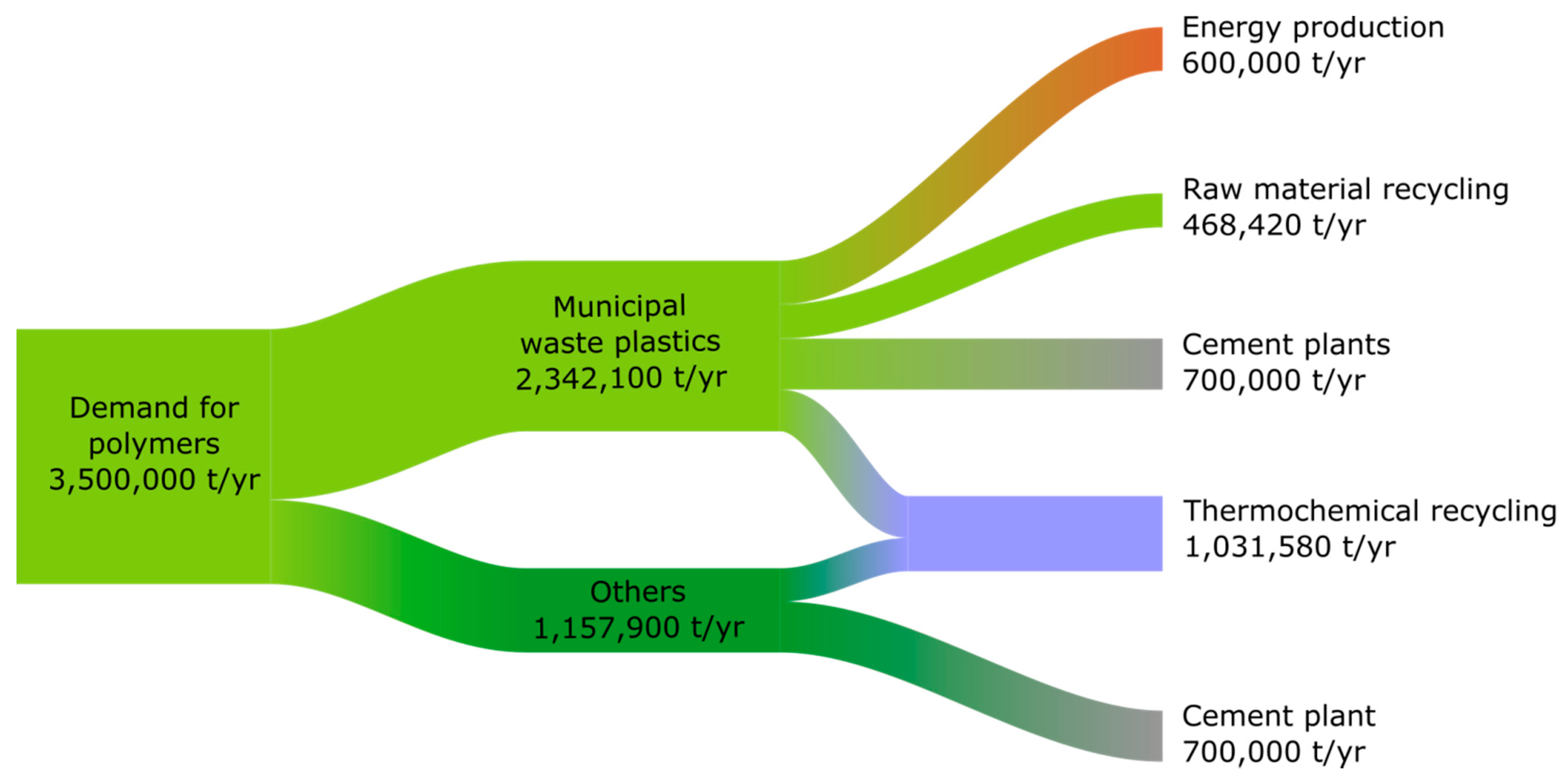
For the calculated estimated plastics waste streams, a structure scheme of plastics waste management in Poland for 2030 and 2050 was created. The following assumptions were made for the calculations:
  • The level of separate collection of plastics waste in Poland will be 60% in 2030 and 75% in 2050;
  • The content of plastics waste in RDF remains constant over time at around 40%;
  • About 20% of plastics waste in 2030 and 30% in 2050 are subject to raw material recycling;
  • In 2030, 1.4 million plastics waste will be disposed of in cement plants, half of which will come from municipal waste;
  • In 2030, 1.5 million tonnes of RDF (0.6 million tonnes of plastics waste) will be used for energy;
  • In 2050, waste fuels for energy production and in cement plants will be replaced by renewable fuels (no use of alternative fuel in the form of plastics waste and RDF);
  • There is no accumulation of plastics in the circulation, i.e., the amount of plastics waste is equal to the amount of demand;
  • The plastics waste stream from non-municipal sectors is the result of the difference between the plastics demand stream and the amount of plastics waste in municipal waste;
  • Plastics waste from non-municipal sectors will supply the other half of the plastics waste demand of cement plants in 2030;
  • The surplus plastics waste stream over and above the amount used in cement plants, waste incineration plants, or recovered in raw material recycling is recycled into feedstock;
  • The morphological composition of municipal waste is unchanged over time and amounts to paper—10%, metal—2.6%, plastics—15%, glass—10%, other—62.4%.
Figure 5 and Figure 6 show the distribution scheme of the total plastics waste stream in Poland in 2030 and 2050. For the adopted assumptions, the estimated total amount of plastics waste that can be used in raw material (thermochemical) recycling will be 1.032 million tonnes in 2030 and 4.528 million tonnes in 2050, respectively.
For the purposes of the gasification balance, it was assumed that plastics waste from the municipal waste sector goes to gasification in the form of RDF (40% of the plastics waste content). The developed plastics waste distribution model is also presented in the article [52].

2.6. Fuel Characteristic

Table 4 and Table 5 present characteristics of fuels used in the process of olefins production. The analysis was based on coal from the “ZW Janina” mine, considered as a potential raw material for the development of gasification technology in Poland (the research was carried out within the project “Development of coal gasification technology for high-efficiency production of fuels and energy”, Task No. 3 of the Strategic Program for Research and Development: “Advanced energy generation technologies” funded by the Polish National Center for Research and Development). In the cases for the production of syngas from natural gas in the autothermal reactor, high-methane group E natural gas was used for the analysis (Table 5). The RDF composition was assumed on the basis of elemental analyses of a number of RDF samples carried out as part of previous work carried out at the Institute for Chemical Processing of Coal.
As mentioned before, it was assumed that RDF (Table 4) goes to gasification contains 40% of the plastics waste.

2.7. Estimation of Investment and Operating Costs

The investment cost estimates were made using the exponential, factor, and price growth index methods. The exponential method is based on the assumption that the investment outlays for a specific implementation scale are known, and the investment outlays for another scale are converted using a scaling exponent, depending on the technology under consideration and assuming most often values in the range 0.5–0.8. Table 6 summarizes the individual main items of equipment, their reference scales, investment costs, and adopted scaling exponents. The data was obtained from NETL studies and analyses as well as our own experience and expertise. The value of expenditures on auxiliary installations was assumed as 14.2% of capital expenditures on other items. For the analysis of systems with a production scale significantly larger than the baseline, multiple parallel plants with a scale close to the baseline were assumed.
The method consists in determining the costs of purchasing the equipment of the considered installation (delivery of machines, apparatus, devices), and then using appropriate indicators to estimate sub-costs and total investment costs. For the main units, the indicators determined based on NETL studies [46] and own data were assumed (Table 7). It was assumed that the capital expenditure for the installation is determined as Total Plant Cost (TPC).
In this paper, the chemical plant construction cost growth index (CEPCI) was used. The calculations were made for 2019. Additionally, a trend line for the CEPCI index was determined based on historical data, thanks to which the estimated value of the index in 2030 was determined, which is 746.5, while in 2050 is 968.8.
The estimation of production costs was carried out based on the assumptions presented in Table 8.

3. Results

3.1. Results of Process Calculations—Distribution of Carbon Element in Analyzed Systems

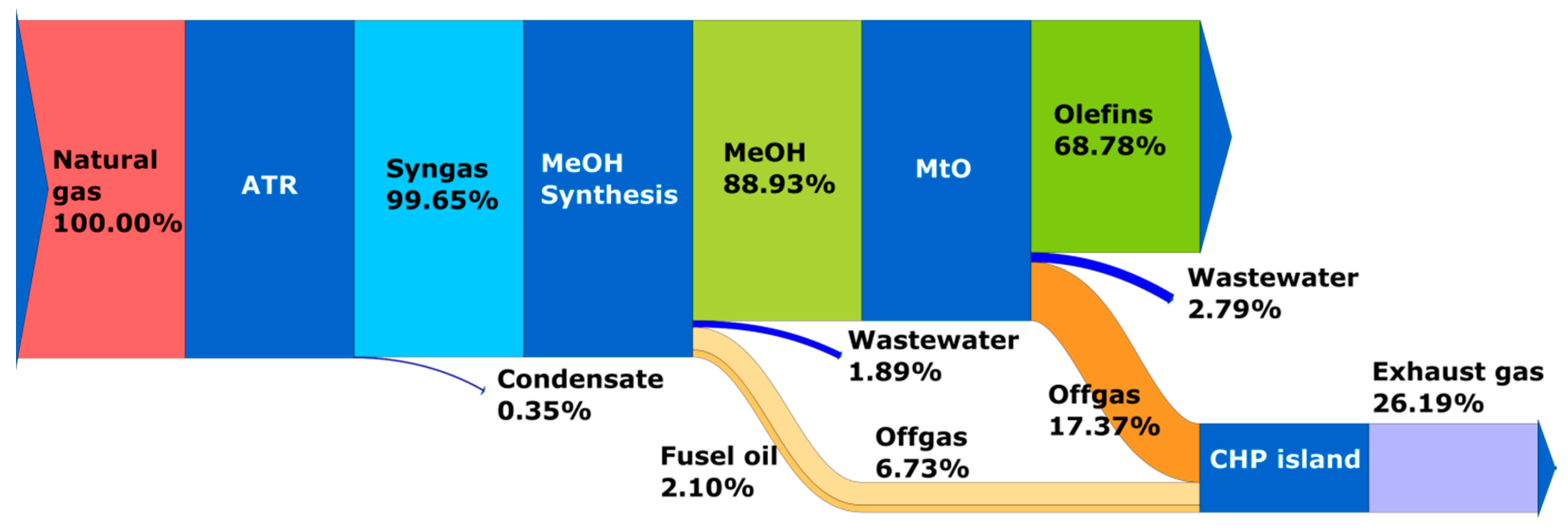
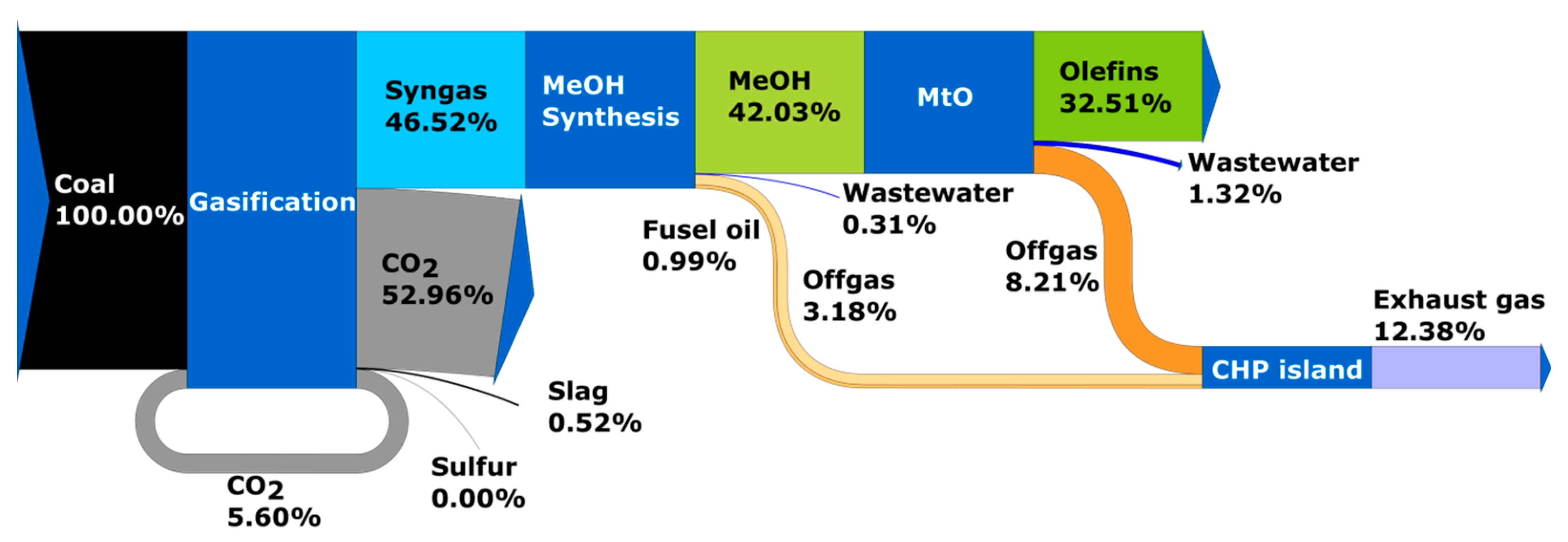
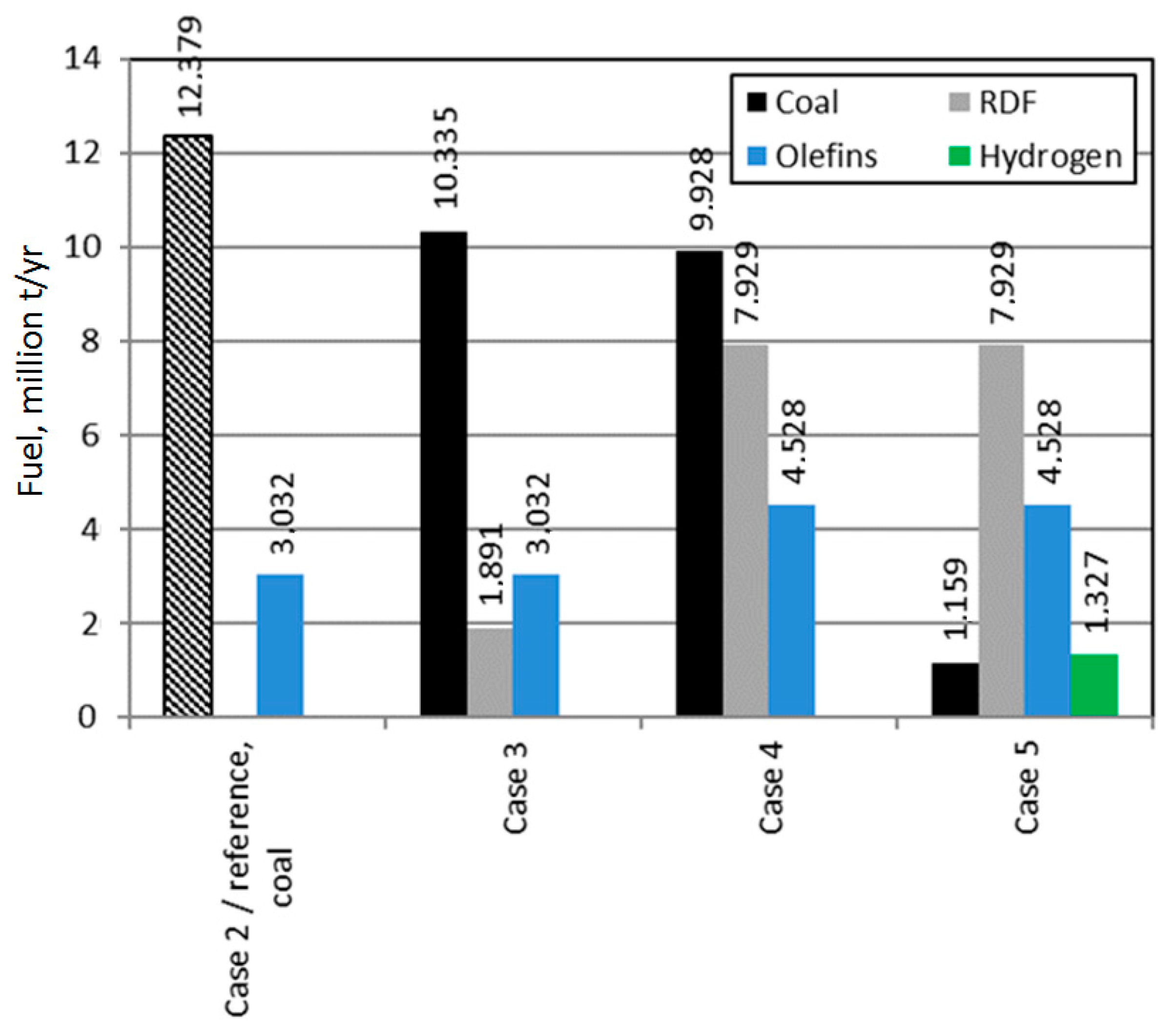
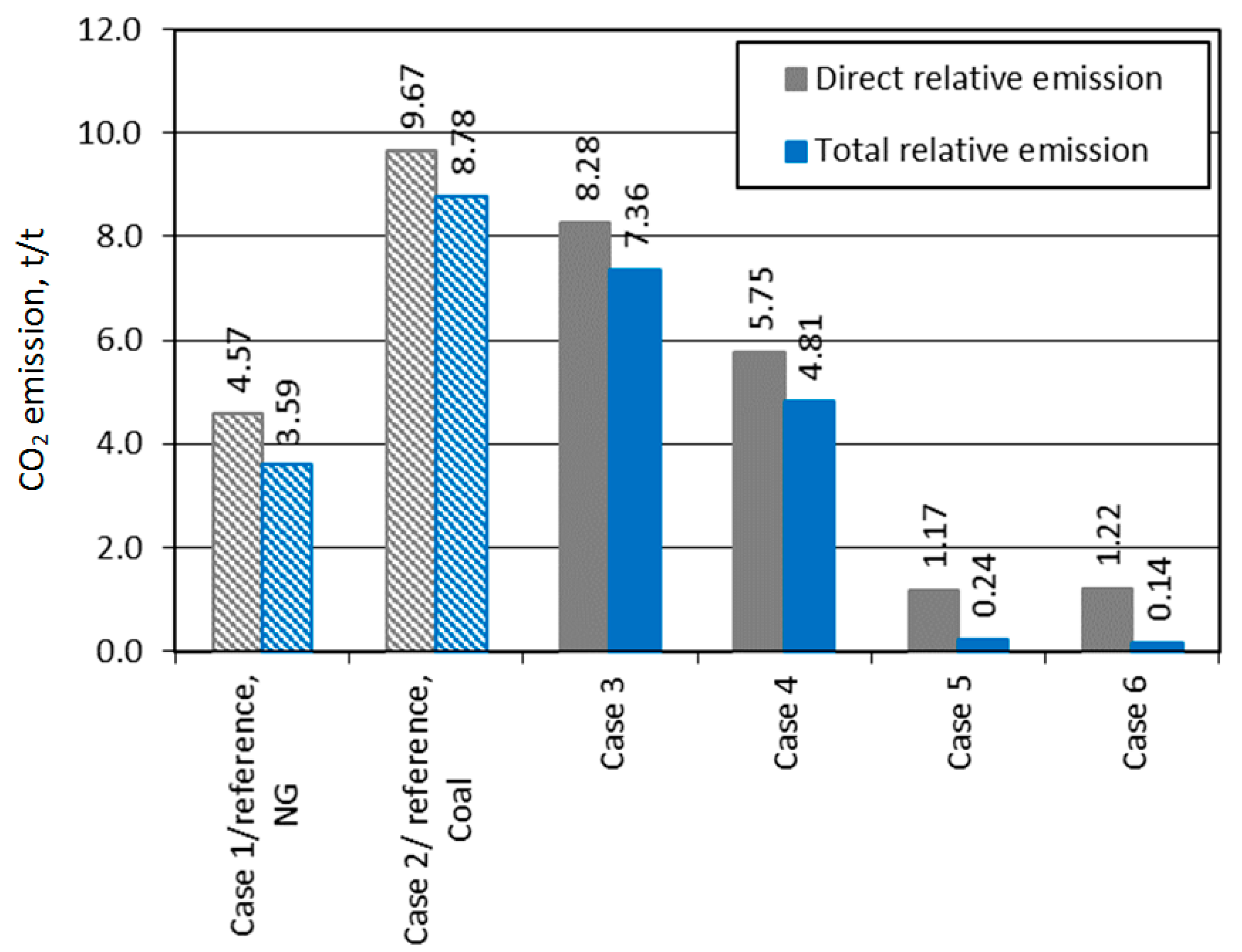
In Cases 1 and 2 (linear economy), the system of olefins production from natural gas and coal for the base year 2030 was analyzed. The analyzed systems, according to the assumptions made have a capacity of approx. 3.032 million t/yr of olefins, with the consumption of 7.056 million t/yr of gas and 12.379 million t/yr of hard coal. Figure 7 and Figure 8 show the distribution of the carbon element for Cases 1 and 2, respectively. The CO2 emission accompanying the production process is 13.850 million and 29.304 million t/yr and 4569 kg and 9666 kg CO2/t of olefins produced for the system using natural gas and hard coal.
In the case of using gas, the main emission sources in the system are the energy utilization of plastics waste (approx. 68.8%) and the emission resulting from the combustion of off-gases (approx. 26.2%).
In the case of using hard coal, the primary source of emissions is carbon dioxide separated from synthesis gas (approx. 53% of emissions), followed by the energy utilization of plastics waste (approx. 32.5%) and the emission from utilization of off-gases (approx. 12.4%).
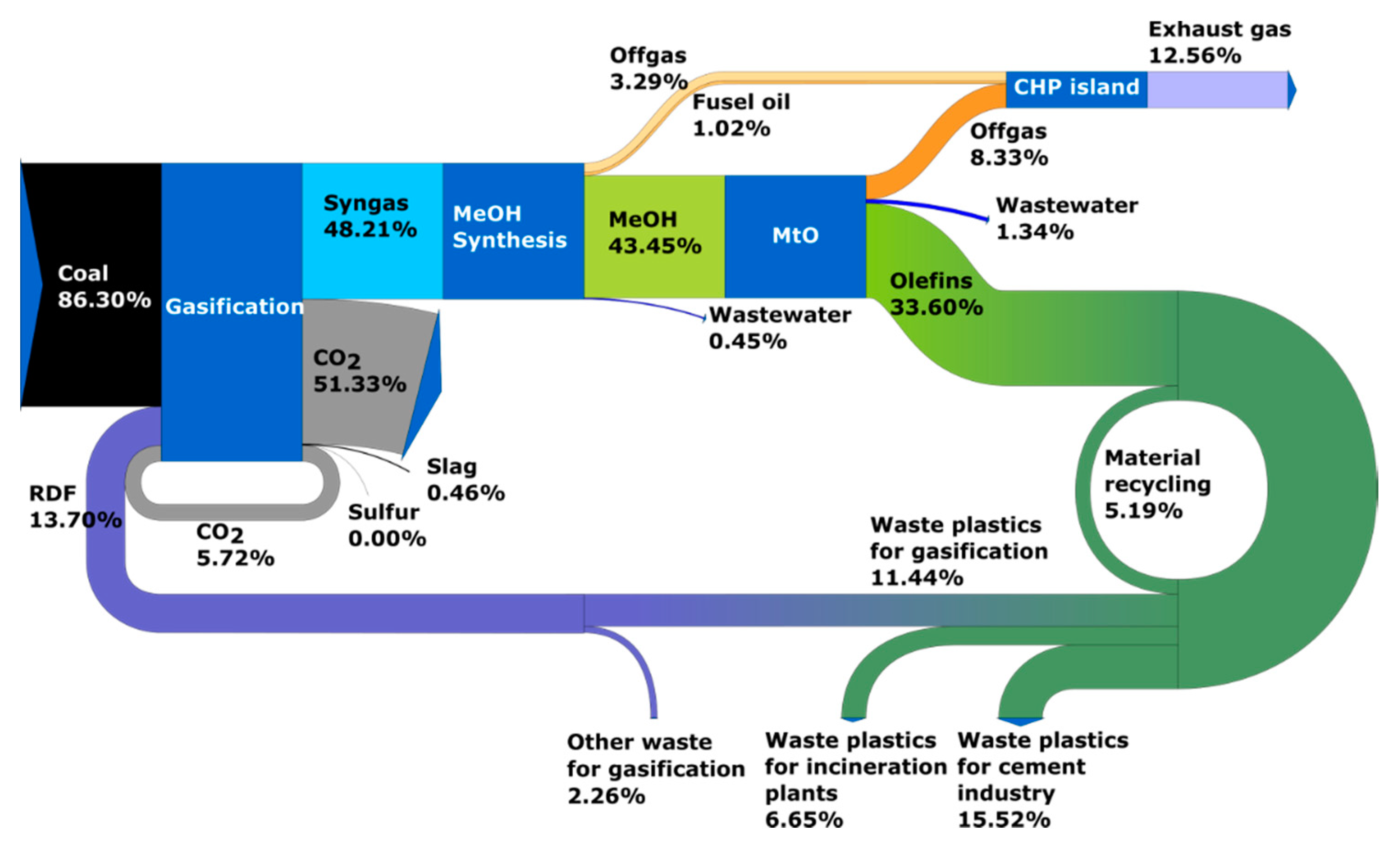
In Case 3, the system of olefins production from a mixture of hard coal and RDF for the base year 2030 was analyzed. The analyzed system has a capacity of approximately 3.032 million t/yr of olefins. In 2030, it is assumed that part of the plastics waste will continue to be recycled for energy (cement plants, waste incinerators plants) and only the unused surplus will be used in a gasification process for olefins production. Carbon element distribution for analyzed case was presented in Figure 9. The CO2 emission with the production process is 25.107 million t/yr, which gives a specific emission of 8282 kg CO2/t of olefins. Main sources of emission in the system are CO2 separated from the syngas (approx. 51.3% of total carbon input), plastics waste utilized in cement industry (approx. 15.5% of total carbon input), utilization of off-gases (approx. 12.6% of total carbon input), and plastics waste utilized in incineration plants (approx. 6.7% of total carbon input). Due to large amount of plastics waste being utilized in cement industry and incineration plants, implementation of RDF recycling resulted in reduction of specific CO2 emissions by only 14.3% and reduction of hard coal consumption by 16.5% compared to Case 2.
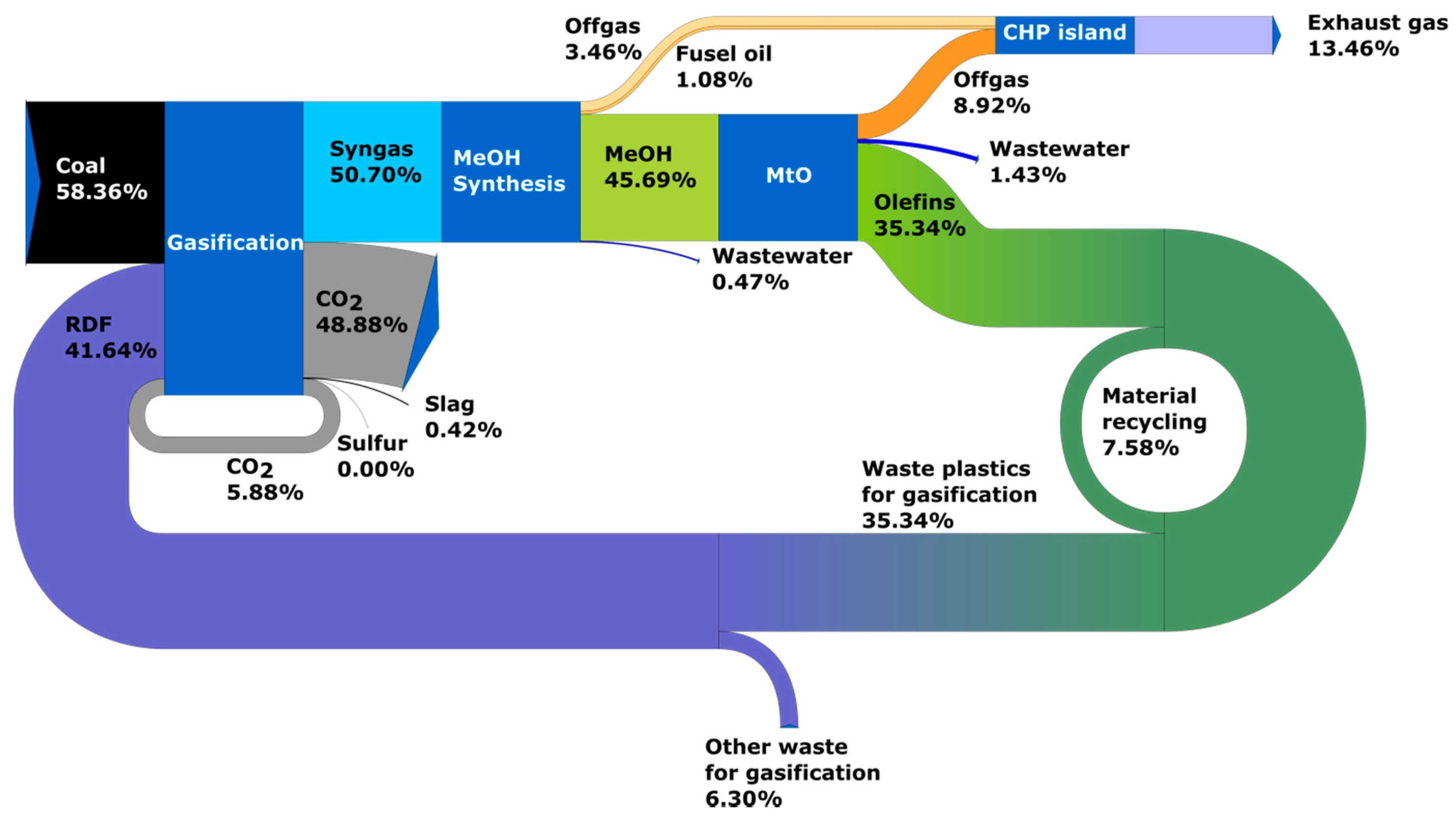
In Case 4 (Figure 10), olefins from hard coal and RDF production system for year 2050 was analyzed. The analyzed system has capacity of 4.528 million t/yr of olefins. It was assumed that in 2050 entire stream of plastics waste will be recycled for gasification. The CO2 emissions associated with the production process is 26.037 million t/yr, which gives a specific emission of 5750 kg CO2/t of olefins. Main sources of emission in the system are CO2 separated from the syngas (approx. 48.9% of total carbon input) and utilization of off-gases (approx. 13.5% of total carbon input). Implementation of full plastics waste recycling allowed to reduce specific emission by 40.5% and hard coal consumption by 19.8% comparing to Case 2 (linear economy, olefins production from hard coal).
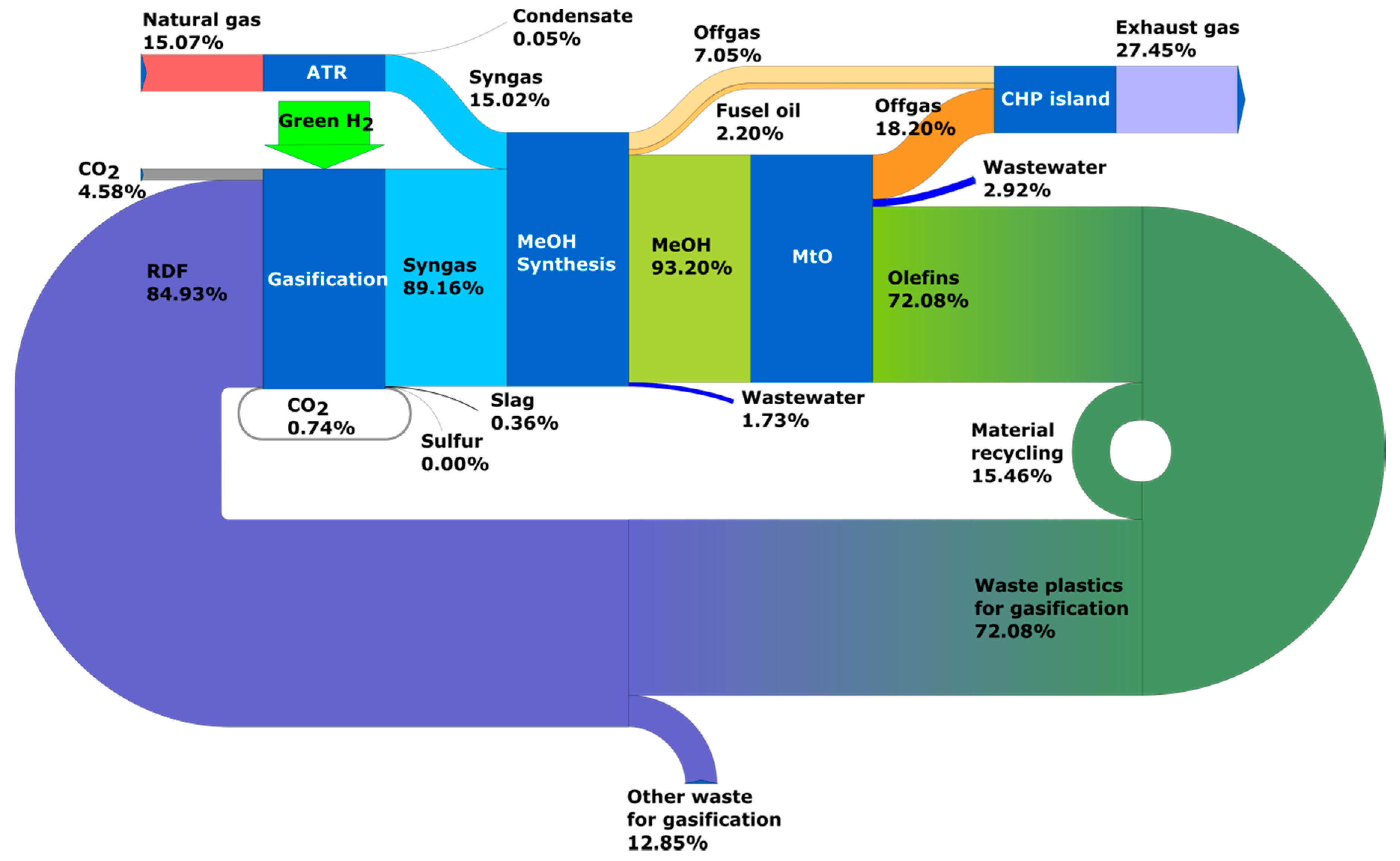
In Cases 5 and 6 (Figure 11 and Figure 12), the entire stream of plastics waste will be recycled for gasification. The analyzed systems have capacity of 4.528 million t/yr of olefins. ‘Green hydrogen’ and some small amount of CO2 are fed into the system to achieve the right composition of syngas. The CO2 emissions associated with the production process are 5.281 and 5.512 million t/yr which yields 1166 and 1217 kg CO2/t of olefins, respectively, for the case using hard coal (Case 5) and natural gas (Case 6).
In both cases, main source of CO2 emission in the system is utilization of off-gases (approx. 27.8% for hard coal and 27.5% for natural gas). Implementation of full plastics waste recycling and addition of ‘green hydrogen’ (Case 5) resulted in significant reduction of specific CO2 emissions by 80% and hard coal consumption by 88% comparing to Case 4. For Case 6, specific CO2 emissions were reduced by 73% and natural gas consumption by 86% compared to Case 1.
A summary of the main balance sheet results resulting from the modelling is presented in Table 9. Assumption were made to balance the system by the heat demand and steam surplus production is used for electricity generation.

3.2. Economic Analysis

As part of the economic analysis, for each of the analyzed cases, estimates were made of the total capital investment and the olefins production costs (excluding financing costs). Capital investments and production costs for analyzed cases were presented in Table 10.

4. Discussion

To cover the national demands for olefins by 2030 more than 12 million tonnes of hard coal will be needed (Case 2, Figure 13). The introduction of circular carbon economy could enable significant substitution of hard coal with plastics waste and, in consequence, reduce its consumption (Cases 3–5, Figure 13). In addition, the energy use of plastics waste would be replaced by more environmentally friendly feedstock recycling. Taking into account the distribution model adopted for plastics waste, their use would reduce relative hard coal consumption by 16.5% by 2030 (Case 3, Table 9, Figure 13).
Losses of the carbon in the production process and the availability of RDF make that the role of hard coal in the olefins production process will be extremely important in the 2030 perspective (Case 3, Figure 13). To cover the national demands for olefins by 2030 more than 10 million tonnes of hard coal will be needed. The scale of production would require the construction of about 11–16 production lines (11–16 gasifiers). Given the short-term development of this direction, the demonstration plant of the first system should start in 2030 and gradually increase the volume of production by 2050, taking into consideration the increase in demand for olefins and availability of RDF.
An important premise for that direction of development, apart to the reduction of CO2 emissions (16% total emission, Figure 14), is the possibility of decreasing the production costs by 21% and 20% compared to olefins production from hard coal and natural gas, respectively (Table 10, Figure 15).
The change in the amount of plastics waste in 2050, including their use only for material and feedstock recycling, contributes to reducing the demand of hard coal in olefins production (Case 4, Figure 13). Despite of prognosing full feedstock recycling of plastics waste, the increase in olefins demand makes that it will still be necessary to use around 10 million tonnes of hard coal in 2050 (Case 4, Figure 13).
The introduction of circular carbon economy in 2050 contributes to approx. 41% reduction of relative direct CO2 emissions associated with the production process (Case 4, Figure 14). The unit production cost of olefins is also decreased (Case 4, Figure 15).
The use of ‘green hydrogen’, significantly reduces the hard coal consumption (Case 5, Table 9, Figure 13) and minimized the relative CO2 emissions (Figure 14). The addition of external ‘green hydrogen’ into the production system allows to obtain the required syngas composition without CO conversion unit (water-gas shift reaction) and the separation of excess CO2 (the main source of emission).
However, it should be remembered that this solution requires 47 TWh of electricity to be supplied to the production system (Case 6). It strongly increases production costs and requires 6 GW of installed capacity. Moreover, it requires solving a number of issues related to, for example, necessity of reduction the investment and operating costs of ‘green hydrogen’ production systems and providing high availability of the H2 production system, with an assumed 90% availability of the olefins production system. That means the necessity to store green energy either in the form of electricity or in the form of hydrogen. Another alternative could be to produce hydrogen from biomass using the gasification process. In that case, this would require an annual biomass consumption of 22 million tonnes.
As expected, the use of natural gas (Case 1) has a significant impact on reducing the CO2 emissions per unit of 53% in relation to the base case with hard coal (Case 2). The introduction of feedstock recycling (Case 4, 2050) reduces this gap to 20.5%. When using ‘green hydrogen’, both the hard coal (Case 5) and natural gas (Case 6) cases have very low CO2 emissions rates (Figure 14). However, the use of natural gas increases the production costs and makes Poland dependent on external supplies of that raw material. A reasonable alternative to the use of natural gas is the introduction of a circular carbon economy and the use of hard coal, which will allow to achieve comparable CO2 emissions at reduced production costs.
The main challenge related to the implementation of the circular carbon economy is the development of a new one or adaptation of the existing gasification technology. Due to the short time perspective and the necessity to incur high costs, it seems that the development of waste gasification in Poland should be based on commercial technology and its adaptation to waste gasification in domestic conditions. The adaptation to be carried out should include the development of systems accompanying the gasification process, such as the technology of waste fuel preparation, including thermal processing, grinding, and compaction. Another important direction is research on low-emission methods of hydrogen production. At the same time, in addition to process and environmental efficiency, the possibility of production in large-scale systems should also be taken into account. At present, the only technologies allowing large-scale production are those based on fossil fuels. An interesting solution enabling emission-free production of hydrogen is the currently developed technology of methane pyrolysis [54,55].
The discussed issues are unique, and analogous studies have been carried out only for the conditions of the German economy [2,14].

5. Conclusions

Chemical recycling is one of the promising options to solve the waste problem by reusing it in production processes. Currently, for large scale solutions the only option having references in industrial scale are thermochemical methods, in particular gasification processes and, to a lesser extent, liquefaction, and hydrogenation. However, their use is associated with CO2 emissions and requires feedstock substitution with hydrocarbon fuels to replicate plastic production. The obtained results show the technical and economic feasibility of the proposed solution, which does not mean that there is no need to look for new solutions and scenarios to solve the problem of waste recycling in a process- and economically-efficient way. Apart from plastics conversion methods, an important direction seems to be to solving the problem of transport and storage of CO2, which would contribute to the reduction of its emissions.
In addition to activities of a technical nature, legal and organizational activities are also extremely important, including the following:
  • Verification of the current waste fuel distribution and its medium- and long-term availability;
  • Detailed analysis of the waste fuels properties and their fluctuation;
  • Changing the national policy in the field of chemical industry development.
The article presents the concept and results of analyses of the possibility of applying circular carbon economy on the example and under Polish conditions for four different scenarios. These scenarios (Cases 3–6) were compared with two reference scenarios (Cases 1–2) based on the linear economy. The carried out analyzes showed that coal and RDF waste fuels can be a valuable source of raw material for the development of the chemical industry in Poland, including satisfying the raw material needs in the field of olefins production. This approach allows for the introduction of a circular economy and the development of the chemical sector using the national resource base. Satisfy the expected needs for chemical products—olefins will require the use of coal as a chemical feedstock. Its required consumption due to the assumed availability of plastics waste and the loss of carbon in the production process is estimated at 10 million t/yr, both in the medium- and long-term.
Introduction of circular economy including the progressive substitution of coal in the production of fuels from waste will reduce CO2 emissions per unit of 17% and 41% respectively in 2030 and 2050 (in comparison to Case 2). A significant reduction in coal consumption can be expected when an additional source of ‘green hydrogen’ is used in chemical production. In this case, the coal consumption can be practically reduced to zero, and CO2 emissions are reduced by 98%. The study assumes that the development of the ‘green hydrogen’ technology will enable the application of such a solution in the perspective of 2050. The use of natural gas for olefins production is characterized by a significantly lower unit emission compared to coal (a reduction of 53% in relation to the reference case with coal, Case 2). A reasonable alternative to the use of natural gas is the introduction of a circular economy and the use of hard coal, which will allow to achieve comparable CO2 emissions at reduced production costs.
The novelty of the research is an attempt to comprehensively assess the technical and economic feasibility of introducing the circular economy for the conditions and on the scale of the whole Polish economy, as well as to quantitatively identify the necessity of substituting recycled waste with hydrocarbon fuels (coal in this case). The obtained results could be the basis for: development of the roadmap for the transformation of the linear into a circular carbon economy using domestic coal resources and providing prospects for sustainable economic development of regions strongly associated with the mining industry.

Author Contributions

Conceptualization, A.S., T.C. and J.B.; methodology, T.C., J.B., A.S., T.B. and R.F.; software, T.C., T.B. and R.F.; validation, T.C., T.B. and J.P.; investigation, J.B. and T.C.; resources, T.C., T.B. and J.P.; data curation, T.C., T.B., R.F. and J.P.; writing—original draft preparation, T.C., J.B., T.B., R.F., J.P. and A.S.; writing—review and editing, R.F., J.B., T.B. and T.C.; visualization, T.B., R.F. and J.P.; supervision, A.S., T.C. and J.B. All authors have read and agreed to the published version of the manuscript.

Funding

The results presented in this publication were obtained during the research project no. “Development of a Roadmap for effective utilization of hard coal and lignite national resources at minimizing CO2 emissions” financed by the Ministry of Science and Higher Education as part of subsidies for the maintenance of research potential.

Institutional Review Board Statement

Not applicable.

Informed Consent Statement

Not applicable.

Data Availability Statement

Not applicable.

Conflicts of Interest

The authors declare no conflict of interest.

References

  1. Khan, I.; Kabir, Z. Waste-to-Energy Generation Technologies and the Developing Economies: A Multi-Criteria Analysis for Sustainability Assessment. Renew. Energy 2020, 150, 320–333. [Google Scholar] [CrossRef]
  2. Lee, R.P.; Keller, F.; Meyer, B. A Concept to Support the Transformation from a Linear to Circular Carbon Economy: Net Zero Emissions, Resource Efficiency and Conservation through a Coupling of the Energy, Chemical and Waste Management Sectors. Clean Energy 2017, 1, 102–113. [Google Scholar] [CrossRef] [Green Version]
  3. Szostak, E.; Duda, P.; Duda, A.; Górska, N.; Fenicki, A.; Molski, P. Characteristics of Plastic Waste Processing in the Modern Recycling Plant Operating in Poland. Energies 2020, 14, 35. [Google Scholar] [CrossRef]
  4. Wielgosiński, G.; Czerwińska, J.; Szufa, S. Municipal Solid Waste Mass Balance as a Tool for Calculation of the Possibility of Implementing the Circular Economy Concept. Energies 2021, 14, 1811. [Google Scholar] [CrossRef]
  5. Kijo-Kleczkowska, A.; Gnatowski, A. Recycling of Plastic Waste, with Particular Emphasis on Thermal Methods—Review. Energies 2022, 15, 2114. [Google Scholar] [CrossRef]
  6. da Silva, L.F.; Resnitzkyd, M.H.C.; Santibanez Gonzalez, E.D.R.; de Melo Conti, D.; da Costa, P.R. Management of Plastic Waste and a Circular Economy at the End of the Supply Chain: A Systematic Literature Review. Energies 2022, 15, 976. [Google Scholar] [CrossRef]
  7. Evode, N.; Qamar, S.A.; Bilal, M.; Barceló, D.; Iqbal, H.M.N. Plastic Waste and Its Management Strategies for Environmental Sustainability. Case Stud. Chem. Environ. Eng. 2021, 4, 100142. [Google Scholar] [CrossRef]
  8. Keller, F.; Voss, R.L.; Lee, R.P.; Meyer, B. Life Cycle Assessment of Global Warming Potential of Feedstock Recycling Technologies: Case Study of Waste Gasification and Pyrolysis in an Integrated Inventory Model for Waste Treatment and Chemical Production in Germany. Resour. Conserv. Recycl. 2022, 179, 106106. [Google Scholar] [CrossRef]
  9. Schwarz, A.E.; Ligthart, T.N.; Godoi Bizarro, D.; De Wild, P.; Vreugdenhil, B.; van Harmelen, T. Plastic Recycling in a Circular Economy; Determining Environmental Performance through an LCA Matrix Model Approach. Waste Manag. 2021, 121, 331–342. [Google Scholar] [CrossRef]
  10. De Pascale, A.; Arbolino, R.; Szopik-Depczyńska, K.; Limosani, M.; Ioppolo, G. A Systematic Review for Measuring Circular Economy: The 61 Indicators. J. Clean. Prod. 2021, 281, 124942. [Google Scholar] [CrossRef]
  11. Kirchner, M.; Sommer, M.; Kratena, K.; Kletzan-Slamanig, D.; Kettner-Marx, C. CO2 Taxes, Equity and the Double Dividend—Macroeconomic Model Simulations for Austria. Energy Policy 2019, 126, 295–314. [Google Scholar] [CrossRef]
  12. Lee, R.P. Alternative Carbon Feedstock for the Chemical Industry?—Assessing the Challenges Posed by the Human Dimension in the Carbon Transition. J. Clean. Prod. 2019, 219, 786–796. [Google Scholar] [CrossRef]
  13. Fogt Jacobsen, L.; Pedersen, S.; Thøgersen, J. Drivers of and Barriers to Consumers’ Plastic Packaging Waste Avoidance and Recycling—A Systematic Literature Review. Waste Manag. 2022, 141, 63–78. [Google Scholar] [CrossRef] [PubMed]
  14. Lee, R.P.; Tschoepe, M.; Voss, R. Perception of Chemical Recycling and Its Role in the Transition towards a Circular Carbon Economy: A Case Study in Germany. Waste Manag. 2021, 125, 280–292. [Google Scholar] [CrossRef] [PubMed]
  15. Schöggl, J.-P.; Stumpf, L.; Baumgartner, R.J. The Narrative of Sustainability and Circular Economy—A Longitudinal Review of Two Decades of Research. Resour. Conserv. Recycl. 2020, 163, 105073. [Google Scholar] [CrossRef]
  16. Acerbi, F.; Taisch, M. A Literature Review on Circular Economy Adoption in the Manufacturing Sector. J. Clean. Prod. 2020, 273, 123086. [Google Scholar] [CrossRef]
  17. Cobo, S.; Dominguez-Ramos, A.; Irabien, A. From Linear to Circular Integrated Waste Management Systems: A Review of Methodological Approaches. Resour. Conserv. Recycl. 2018, 135, 279–295. [Google Scholar] [CrossRef]
  18. Tsai, F.M.; Bui, T.-D.; Tseng, M.-L.; Lim, M.K.; Hu, J. Municipal Solid Waste Management in a Circular Economy: A Data-Driven Bibliometric Analysis. J. Clean. Prod. 2020, 275, 124132. [Google Scholar] [CrossRef]
  19. Lahane, S.; Kant, R.; Shankar, R. Circular Supply Chain Management: A State-of-Art Review and Future Opportunities. J. Clean. Prod. 2020, 258, 120859. [Google Scholar] [CrossRef]
  20. Mhatre, P.; Panchal, R.; Singh, A.; Bibyan, S. A Systematic Literature Review on the Circular Economy Initiatives in the European Union. Sustain. Prod. Consum. 2021, 26, 187–202. [Google Scholar] [CrossRef]
  21. Thunman, H.; Berdugo Vilches, T.; Seemann, M.; Maric, J.; Vela, I.C.; Pissot, S.; Nguyen, H.N.T. Circular Use of Plastics-Transformation of Existing Petrochemical Clusters into Thermochemical Recycling Plants with 100% Plastics Recovery. Sustain. Mater. Technol. 2019, 22, e00124. [Google Scholar] [CrossRef]
  22. Al-Salem, S.M.; Antelava, A.; Constantinou, A.; Manos, G.; Dutta, A. A Review on Thermal and Catalytic Pyrolysis of Plastic Solid Waste (PSW). J. Environ. Manage. 2017, 197, 177–198. [Google Scholar] [CrossRef] [PubMed]
  23. Yoshioka, T.; Grause, G.; Eger, C.; Kaminsky, W.; Okuwaki, A. Pyrolysis of Poly(Ethylene Terephthalate) in a Fluidised Bed Plant. Polym. Degrad. Stab. 2004, 86, 499–504. [Google Scholar] [CrossRef]
  24. Lopez, G.; Artetxe, M.; Amutio, M.; Bilbao, J.; Olazar, M. Thermochemical Routes for the Valorization of Waste Polyolefinic Plastics to Produce Fuels and Chemicals. A Review. Renew. Sustain. Energy Rev. 2017, 73, 346–368. [Google Scholar] [CrossRef]
  25. Zhuang, J.; Tang, J.; Aljerf, L. Comprehensive Review on Mechanism Analysis and Numerical Simulation of Municipal Solid Waste Incineration Process Based on Mechanical Grate. Fuel 2022, 320, 123826. [Google Scholar] [CrossRef]
  26. Chen, H.; Zhang, M.; Wu, Y.; Xu, G.; Liu, W.; Liu, T. Design and Performance Evaluation of a New Waste Incineration Power System Integrated with a Supercritical CO2 Power Cycle and a Coal-Fired Power Plant. Energy Convers. Manag. 2020, 210, 112715. [Google Scholar] [CrossRef]
  27. Voss, R.; Lee, R.P.; Seidl, L.; Keller, F.; Fröhling, M. Global Warming Potential and Economic Performance of Gasification-Based Chemical Recycling and Incineration Pathways for Residual Municipal Solid Waste Treatment in Germany. Waste Manag. 2021, 134, 206–219. [Google Scholar] [CrossRef]
  28. Solis, M.; Silveira, S. Technologies for Chemical Recycling of Household Plastics—A Technical Review and TRL Assessment. Waste Manag. 2020, 105, 128–138. [Google Scholar] [CrossRef]
  29. Paukov, A.; Magaril, R.; Magaril, E. An Investigation of the Feasibility of the Organic Municipal Solid Waste Processing by Coking. Sustainability 2019, 11, 389. [Google Scholar] [CrossRef] [Green Version]
  30. Siddiqui, M.N.; Redhwi, H.H. Catalytic Coprocessing of Waste Plastics and Petroleum Residue into Liquid Fuel Oils. J. Anal. Appl. Pyrolysis 2009, 86, 141–147. [Google Scholar] [CrossRef]
  31. Chen, H.; Li, J.; Liu, J.; Li, T.; Xu, G.; Liu, W. Thermodynamic and Economic Evaluation of a Novel Waste-to-Energy Design Incorporating Anaerobic Digestion and Incineration. Energy Convers. Manag. 2022, 252, 115083. [Google Scholar] [CrossRef]
  32. Himanen, M.; Hänninen, K. Composting of Bio-Waste, Aerobic and Anaerobic Sludges—Effect of Feedstock on the Process and Quality of Compost. Bioresour. Technol. 2011, 102, 2842–2852. [Google Scholar] [CrossRef]
  33. Melendez, J.R.; Mátyás, B.; Hena, S.; Lowy, D.A.; El Salous, A. Perspectives in the Production of Bioethanol: A Review of Sustainable Methods, Technologies, and Bioprocesses. Renew. Sustain. Energy Rev. 2022, 160, 112260. [Google Scholar] [CrossRef]
  34. El-Qelish, M.; Hassan, G.K.; Leaper, S.; Dessì, P.; Abdel-Karim, A. Membrane-Based Technologies for Biohydrogen Production: A Review. J. Environ. Manage. 2022, 316, 115239. [Google Scholar] [CrossRef]
  35. Zheng, Y.; Zhang, Q.; Zhang, Z.; Jing, Y.; Hu, J.; He, C.; Lu, C. A Review on Biological Recycling in Agricultural Waste-Based Biohydrogen Production: Recent Developments. Bioresour. Technol. 2022, 347, 126595. [Google Scholar] [CrossRef] [PubMed]
  36. Sharma, S.; Basu, S.; Shetti, N.P.; Kamali, M.; Walvekar, P.; Aminabhavi, T.M. Waste-to-Energy Nexus: A Sustainable Development. Environ. Pollut. 2020, 267, 115501. [Google Scholar] [CrossRef]
  37. Nanda, S.; Berruti, F. A Technical Review of Bioenergy and Resource Recovery from Municipal Solid Waste. J. Hazard. Mater. 2021, 403, 123970. [Google Scholar] [CrossRef]
  38. Ali, J.; Rasheed, T.; Afreen, M.; Anwar, M.T.; Nawaz, Z.; Anwar, H.; Rizwan, K. Modalities for Conversion of Waste to Energy—Challenges and Perspectives. Sci. Total Environ. 2020, 727, 138610. [Google Scholar] [CrossRef]
  39. Meys, R.; Frick, F.; Westhues, S.; Sternberg, A.; Klankermayer, J.; Bardow, A. Towards a Circular Economy for Plastic Packaging Wastes—The Environmental Potential of Chemical Recycling. Resour. Conserv. Recycl. 2020, 162, 105010. [Google Scholar] [CrossRef]
  40. Shonnard, D.; Tipaldo, E.; Thompson, V.; Pearce, J.; Caneba, G.; Handler, R. Systems Analysis for PET and Olefin Polymers in a Circular Economy. Procedia CIRP 2019, 80, 602–606. [Google Scholar] [CrossRef]
  41. Higman, C.; van der Burgt, M. (Eds.) Gasification, 2nd ed.; Gulf Professional Publishing: Burlington, VT, USA, 2008; ISBN 978-0-7506-8528-3. [Google Scholar]
  42. Kaur, G.; Uisan, K.; Ong, K.L.; Lin, C.S.K. Recent Trends in Green and Sustainable Chemistry & Waste Valorisation: Rethinking Plastics in a Circular Economy. Curr. Opin. Green Sustain. Chem. 2018, 9, 30–39. [Google Scholar] [CrossRef]
  43. Rogelj, J.; Elzen, M.; Höhne, N.; Fransen, T.; Fekete, H.; Winkler, H.; Schaeffer, R.; Sha, F.; Riahi, K.; Meinshausen, M. Paris Agreement Climate Proposals Need a Boost to Keep Warming Well below 2 °C. Nature 2016, 534, 631–639. [Google Scholar] [CrossRef] [PubMed] [Green Version]
  44. Rissman, J.; Bataille, C.; Masanet, E.; Aden, N.; Morrow, W.R.; Zhou, N.; Elliott, N.; Dell, R.; Heeren, N.; Huckestein, B.; et al. Technologies and Policies to Decarbonize Global Industry: Review and Assessment of Mitigation Drivers through 2070. Appl. Energy 2020, 266, 114848. [Google Scholar] [CrossRef]
  45. Aguilar-Hernandez, G.A.; Dias Rodrigues, J.F.; Tukker, A. Macroeconomic, Social and Environmental Impacts of a Circular Economy up to 2050: A Meta-Analysis of Prospective Studies. J. Clean. Prod. 2021, 278, 123421. [Google Scholar] [CrossRef]
  46. Woods, M.; Kuehn, N.; Shah, V.; White lll, C.; Goellner, J. Baseline Analysis of Crude Methanol Production from Coal and Natural Gas; National Energy Technology Laboratory (NETL): Pittsburgh, PA, USA; Morgantown, WV, USA; Albany, OR, USA, 2014.
  47. Xiang, D.; Yang, S.; Liu, X.; Mai, Z.; Qian, Y. Techno-Economic Performance of the Coal-to-Olefins Process with CCS. Chem. Eng. J. 2014, 240, 45–54. [Google Scholar] [CrossRef]
  48. Johansson, E. Process Integration Study of Biomass-to-Methanol (via Gasification) and Methanol-to-Olefins (MTO) Processes in an Existing Steam Cracker Plant; Chalmers University of Technology: Göteborg, Sweden, 2013. [Google Scholar]
  49. Technology Roadmap—Hydrogen and Fuel Cells—Analysis. Available online: https://www.iea.org/reports/technology-roadmap-hydrogen-and-fuel-cells (accessed on 3 June 2022).
  50. KOBIZE. Available online: https://www.kobize.pl/ (accessed on 7 June 2022).
  51. Lubiewa-Wieleżyński, W. Forecasts of Chemical Industry Production in Poland until 2020. Warszawa, Poland. 2014; unpublished. [Google Scholar]
  52. Chmielniak, T.; Bigda, J.; Billig, T.; Popowicz, J.; Fryza, R.; Sobolewski, A. The waste distribution model in Poland in the context of introducing the circular carbon economy. The 2030 and 2050 perspectives. Przemysl Chem. 2020, 99, 1529–1533. [Google Scholar] [CrossRef]
  53. Waligórska, M.; Kostrzewa, Z.; Potyra, M.; Rutkowska, L. Population Projection 2014–2050; Demographic Surveys and Labour Market Department, Central Statistical Office: Warsaw, Poland, 2014.
  54. Riley, J.; Atallah, C.; Siriwardane, R.; Stevens, R. Technoeconomic Analysis for Hydrogen and Carbon Co-Production via Catalytic Pyrolysis of Methane. Int. J. Hydrogen Energy 2021, 46, 20338–20358. [Google Scholar] [CrossRef]
  55. Sánchez-Bastardo, N.; Schlögl, R.; Ruland, H. Methane Pyrolysis for CO2-Free H2 Production: A Green Process to Overcome Renewable Energies Unsteadiness. Chem. Ing. Tech. 2020, 92, 1596–1609. [Google Scholar] [CrossRef]
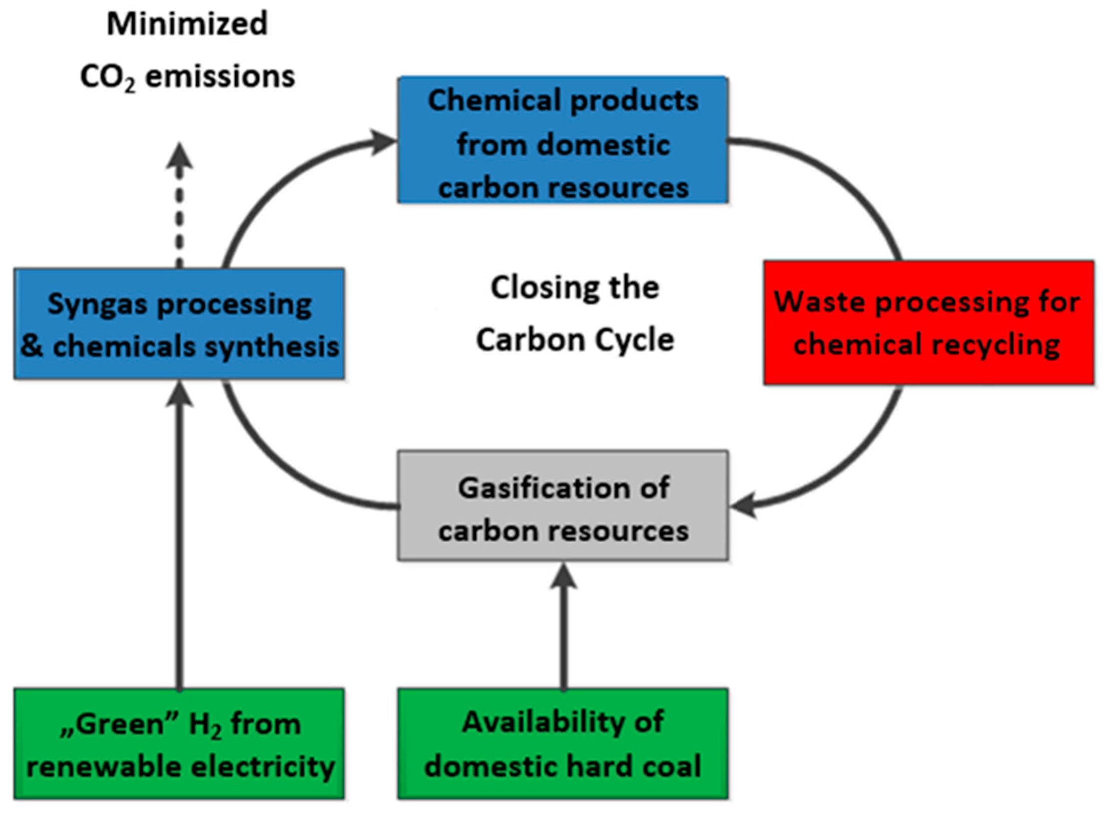
Figure 1. Transformation from a linear to circular carbon economy and closing the carbon cycle [2].
Energies 15 04983 g001
Figure 2. Technological configuration of the olefins production system: (a) solid fuels, (b) gaseous fuels.
Energies 15 04983 g002
Figure 3. Process model of the gasification system (Shell Coal Gasification Process (SCGP)—Bottom water quench, ChemCAD v7).
Energies 15 04983 g003
Figure 4. Demand for polymers in the polish economy. Actual data (2010–2015) and projected values (2020–2050).
Energies 15 04983 g004
Figure 5. Distribution scheme of plastic waste in Poland, prognosis for 2030.
Energies 15 04983 g005
Figure 6. Distribution scheme of plastic waste in Poland, prognosis for 2050.
Energies 15 04983 g006
Figure 7. Carbon element distribution in olefins from natural gas production system (2030).
Energies 15 04983 g007
Figure 8. Carbon element distribution in olefins from hard coal production system (2030).
Energies 15 04983 g008
Figure 9. Carbon element distribution in olefins from hard coal and RDF production system (2030).
Energies 15 04983 g009
Figure 10. Carbon element distribution in olefins from hard coal and RDF production system (2050).
Energies 15 04983 g010
Figure 11. Carbon element distribution in olefins from hard coal and RDF production system with addition of ‘green hydrogen’ (2050).
Energies 15 04983 g011
Figure 12. Carbon element distribution in olefins from natural gas and RDF production system with addition of ‘green hydrogen’ (2050).
Energies 15 04983 g012
Figure 13. Consumption of hard coal and RDF and amount production of olefins.
Energies 15 04983 g013
Figure 14. CO2 emissions—olefins production (coal gasification, 2030/2050).
Energies 15 04983 g014
Figure 15. Production cost of olefins (2030/2050).
Energies 15 04983 g015
Table 1. Summary of data on the configuration of the gasification and process gas conversion system.
SpecificationUnitValue
Gasification system
Oxygen production
High pressure ASU
Parameters: O2; 32 °C/8.5 bar; N2: 32 °C/4 bar
Gasification unit
ReactorShell/Quench
Gasification pressurebar42
Ratio O2/C 1kg O2/kg C1.56–1.254 (calculated value, depending on the case under consideration)
Ratio steam/C 1kg H2O/kg C0.119–0.133 (calculated value, depending on the case under consideration)
Conversion rate of the C element %95.0
Calorific value of the gas 2kJ/STC m34806 (calculated value)
Gas cooling

bar
Quench
Convection exchanger,
steam production: HP-60; IP-15.4; LP-5
Oxidant--
Oxygenvol.%95
Steambar60
Fuel transport medium: nitrogenkg/h7920
Pre-treatment of raw gasCyclones, water scrubber
Gas conversion and purification system
WGS UnitYes, II-stage system
CO conversion rate%96
Desulphurization UnitYes, Selexol I-stage
Separation efficiency%92
Sulfur recoveryNone
CO2 separationYes, Selexol
Separation efficiency%92
1 The content of carbon element in the fuel fed to the reactor. 2 Raw gas downstream of gasification reactor/reformer, calorific value.
Table 2. Basic indicators for syngas consumption and production.
IndicatorUnitValue
Consumption of natural gaskg/kgsyngas0.4934
Consumption of oxygenkg/kgsyngas0.5769
Consumption of boiler waterkg/kgsyngas0.1105
Syngas productionkg/kgsyngas1.0000
Condensate productionkg/kgsyngas0.1808
Table 3. Consumption and production basic indicators of methanol and olefins.
IndicatorUnitValue
MeOH synthesis
Consumption of synthesis gaskg/kgMeOH1.18
Electricity consumptionkWh/kgMeOH0.0254
Cooling water consumptionkg/kgMeOH80.2
Steam production (25.5 barg, 227 °C)kg/kgMeOH1.00
Fusel oil productionkg/kgMeOH0.042
Off-gas productionkg/kgMeOH0.126
Wastewater productionkg/kgMeOH0.0135
Olefins synthesis
Cooling water consumptionkg/kgMeOH12.539
Electricity consumptionkWh/kgMeOH0.149
Ethylene productionkg/kgMeOH0.212
Propylene productionkg/kgMeOH0.126
Off-gas productionkg/kgMeOH0.107
Steam productionkg/kgMeOH2.694
Wastewater productionkg/kgMeOH0.554
Table 4. Physicochemical properties of hard coal and RDF.
ParameterSymbolUnitHard CoalRDF
(40% Plastic Waste)
LHV, analyticalQiakJ/kg25,60620,046
HHV, analyticalQsakJ/kg26,71121,526
Ash content, as receivedArwt.%13.018.42
Total carbon content, analyticalCtawt.%64.647.75
Total hydrogen content, analyticalHawt.%4.46.34
Nitrogen content, analyticalNawt.%1.010.92
Total sulphur content, analyticalStawt.%1.50.35
Oxygen content, analyticalOawt.%10.621.22
Moisture content, analyticalWawt.%5.05.00
Ash content, analyticalAawt.%13.018.42
Table 5. Physicochemical properties of natural gas.
ParameterUnitAssumed for CalculationType E Natural Gas
Parameter Range
Methane contentvol.%99.0>96.0
Carbon dioxide contentvol.%1.0≤3.0
Minimal HHVMJ/m338.0≥38.0
Wobbe index rangeMJ/m349.045.0–56.9
Table 6. Summary of basic data for expenditure on plant equipment.
Equipment ItemScaling ParameterUnitValueScaling Exponent Factor
Unloading, preparation and storage of raw material/fuelFuel streamkg/h122,8000.55
GasificationFuel streamkg/h122,8000.55
Gas conditioningGas stream after scrubberkg/h301,5000.60
AGRAGR acid gas streamkg/h58500.57
Sulfur removalSulfur streamkg/h1350.80.58
Methanol synthesisMethanol productionkg/h66,7000.60
ASUOxygen streamkg/h46,7000.50
ATRNatural gas streamkg/h81,2880.60
Olefins synthesisOlefins streamkg/h21,5600.60
ElectrolysisElectric powerMW11.00
Table 7. Summary of the indicators for the estimated sub-costs and total investment costs.
ComponentUnitValue
Apparatus and equipment% 1100
Equipment installation% 125
Installation of instrumentation and control and measurement equipment% 116
Piping installation% 135
Electrical installation% 17
Construction work% 115
Temporary installations% 110
Auxiliary installations% 12
Design and supervision% 133
Other costs% 16
Delivery costs% 112
Contingencies% 140
Commissioning% 15
Fixed assets outlays% 1306
1 In relation to the cost of delivery of equipment.
Table 8. Assumptions for estimating production costs.
ItemUnitValue
Hard coal cost€/t60.98
Income from the utilization of RDF€/t97.82
RDF transportation cost€/t1.62
Natural gas cost€/kg0.32
Process water cost€/m30.70
Cooling water cost€/m30.03
Electricity cost€/MWh52.27
Revenue from the sale of electricity€/MWh52.27
The cost of chemicals, catalysts 1$/t MeOH2.09
The cost of CO2 emissions 2€/t25
Repairs, renovations% from Investment expenditures1.0
Spare parts% from Investment expenditures0.50
Insurance% from Investment expenditures0.50
Labour person/1 installation40
Average salary€/person·yr17,200
Wastewater management€/t1.62
Ash disposal€/t34.09
Profit from the sale of sulfur€/t159.09
Constructions tax 3% from expenditure on buildings2
Building tax 4€/m25.08
Land tax 4€/m20.19
1 Calculation based on NETL data [46]. 2 Euro exchange rate assumed 4.50 PLN. 3 For the calculation of investment expenditures, it was assumed that buildings account for 7% of total investment expenditures. 4 Based on NETL studies [46], it was assumed that 1 installation covers an area of 121,410 m2 and buildings account for 10% of the area.
Table 9. Comparison of raw material and electricity usage, production capacity and main factors values.
ParameterUnitCase 1Case 2Case 3Case 4Case 5Case 6
GtO2030CtO2030RDFCtO2030RDFCtO2050RDFCtO2050H2RDFGtO2050H2
Raw material
Hard coalmillion t/yr-12.37910.3359.9281.159-
RDFmillion t/yr--1.8927.9297.9297.929
Natural gasmillion t/yr5.221----1.121
Gasification island
Oxygen demand 1kg/kg1.1690.7470.7330.7440.7200.779
Steam demand 1kg/kg0.2240.0770.0770.0770.0770.095
CO2 demand 1kg/kg0.0000.1340.1340.1340.1340.117
H2 demand 1kg/kg----0.1460.122
Products
Olefins productionmillion t/yr3.0323.0323.0324.5284.5284.528
Incl. ethylenemillion t/yr1.9011.9011.9012.8402.8402.840
Incl. propylenemillion t/yr1.1301.1301.1301.6881.6881.688
Electricity
Electricity demand 1MWh/t0.3420.4030.4030.4086.3485.173
Gross electricity production 1MWh/t1.1130.6950.7120.7291.1361.027
Net electricity production 1MWh/t0.7710.2930.3100.321−5.2124.146
Net electricity productionTWh/yr4.0233.6213.7845.724−47.367−37.520
Carbon balance
Olefinskg/kg0.68780.32510.33600.35340.72930.7208
Direct CO2 emissionsmillion t/yr13.85029.30425.10726.0375.2815.512
Indirect CO2 emissions 2million t/yr−2.977−2.680−2.800−4.235−4.216−4.881
Total CO2 emissionsmillion t/yr10.87326.62422.30721.8021.0650.630
Specific direct CO2 emissions per productskg/t456996668282575011661,217
Specific indirect CO2 emissions per productskg/t3587878273584814235139
8906 37348 3
1 Consumption and/or production indicators per raw material. 2 Emission created by electricity produced/used by the system. Emission of external production of electricity was set to 740 kg/MWh. 3 Emission including the CO2 emissions from the external electricity demand for water electrolysis. In that case emission of external production of electricity from fossil fuels was set to 740 kg/MWh.
Table 10. Capital investment and production cost comparison for analyzed cases.
CaseBase YearCapital
Investment
Production
Cost per Year
Specific
Production Cost
Million PLNMillion PLNPLN/t Olefins
Linear Economy
1203033,910.27664.52528.2
2203057,381.96640.72190.5
Circular Economy
3203058,561.94645.21532.3
4205084,807.62962.4654.2
52050100,412.210,620.92345.4
6205094,980.29518.12101.8
Publisher’s Note: MDPI stays neutral with regard to jurisdictional claims in published maps and institutional affiliations.