1. Introduction
Recently, fire accidents in secondary batteries for EVs (electric vehicles) and ESS (energy storage systems) have influenced the battery market in a negative way. In particular, a total of 34 fire accidents occurring in ESS from August 2017 to March 2022 have been reported, hence the need for systematic research to be carried out to reinforce the safety validation of medium- and large-sized secondary batteries [
1,
2,
3,
4,
5].
On the other hand, various battery cell configurations of state-of-art Li-ion battery cells are classified for the different types and sizes of batteries such as cylindrical, prismatic and pouch-type. The thermal management and safety issues are different depending on the battery type and size due to the battery cell containment; therefore, systematic measures to reinforce the safety validation of different types and sizes of Li-ion batteries are required [
6].
It is currently more common to use 21,700 or 4680 Li-ion batteries, which are larger than 18,650 batteries, in medium- and large-sized batteries with cylindrical NCA (nickel aluminum manganese) batteries. Moreover, the medium- and large-sized batteries for ESS or EVs adopt prismatic or pouch-type NMC (nickel manganese cobalt) batteries, which are 10 times larger than the cylindrical type.
Furthermore, existing studies such as the reliability of the calculation method for external short circuits, the investigation of battery safety by performing external short-circuit tests considering the cut-off time of protection devices with cell fuses and module fuses, and the influence of environmental conditions by comparing the preprocessing temperature of batteries in existing research are lacking. Specifically, studies conducted by numerous researchers (Zeyu Chen, Ruixin Yang, Ti Dong, etc.) evaluate the characteristics of external short circuits such as voltage, current and temperature data by considering certain ranges of initial SOC and ambient temperature [
7,
8,
9,
10,
11]. However, the preprocessing temperature, which is the temperature of the battery during the charging operation before the test, is neglected, despite it having a significant influence on the internal resistance of the corresponding battery samples, and the internal resistance is directly related to the external short-circuit current. Additionally, these existing evaluation methods performed external short-circuit tests merely targeting cylindrical batteries. In other words, none of the studies carried out so far involved external short circuits in medium- and large-sized batteries, while most of the battery types adopted in ESS are medium- and large-sized ones such as prismatic and pouch-type.
Therefore, in order to evaluate the influence of preprocessing temperature and types and sizes of batteries on the characteristics of external short circuits, this paper implements an accident test device to perform an external short circuit for NMC prismatic and pouch-type batteries, which are widely used in medium and large secondary batteries. This paper presents a safety evaluation method based on SOC and short-circuit resistance through tests on external short circuits, which is one of the typical causes of thermal runaway in lithium-ion batteries, and performs a feasibility study of the test conditions for external short circuits in medium and large lithium-ion batteries, which are currently adopted in EVs and ESS. Furthermore, the characteristics of different types of protection coordination are presented through short-circuit tests with different types of protection devices, which can cut off massive short-circuit currents. In order to confirm the safety in case of a short-circuit fault depending on the installation environment such as temperature and humidity in ESS, this paper presents the characteristics of the short-circuit tests by considering the diverse preprocessing temperatures of the battery, before performing short-circuit testing.
2. Mechanisms of External Short Circuit in Li-Ion Battery
2.1. Fire Accident Cases for External Short Circuit
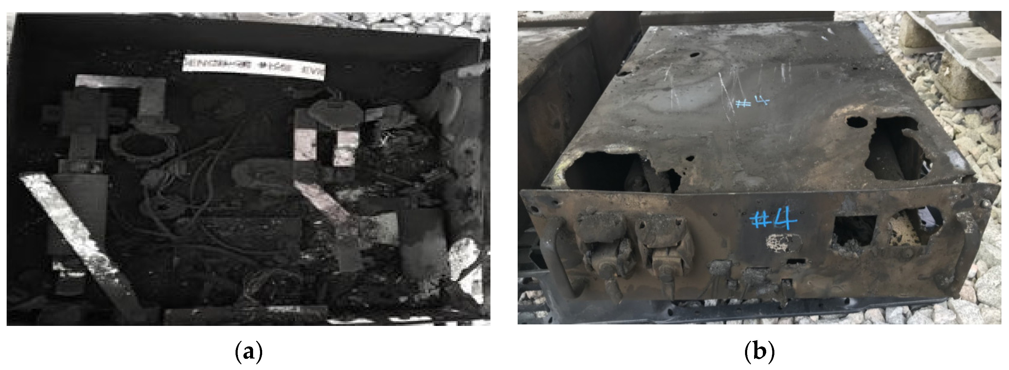
According to the result of a “private–public joint investigation on causes of fire accidents in ESS”, one of the causes is estimated to be a simultaneous fire occurrence due to a secondary short-circuit fault with the destruction of the bus bars at the switch gear box in the battery racks, as shown in
Figure 1. In addition, the mechanism of fire occurrence due to insulation degradation is estimated to be a short-circuit fault caused by a secondary grounding fault in moisture and dust tests. Furthermore, EV manufacturers estimate that fire accidents occur with a short circuit by two line ground faults, which are caused by insulation breakdown due to the leak of antifreeze. On the other hand, external short-circuit tests, which may significantly affect the safety of lithium-ion batteries, are presented in various references.
2.2. Mechanism of External Short Circuit in Li-Ion Battery
In general, the test item of an external short circuit in a Li-ion battery is to determine the criteria of the level of risk by connecting exposed cathode and anode electrodes to a short resistor. During the abovementioned test, a large fault current at the short circuit occurs and then high joule heat is generated in the internal resistance of the battery, which causes the battery temperature to rapidly rise. The high temperature caused by the external short circuit results in the physical deformation of the separator of the battery cell located between the anode and the cathode platforms, and then it leads to an internal short circuit and a serious thermal reaction. Therefore, the battery cell is in thermal runaway, during which the temperature of the battery is rapidly raised, and there is a possibility that a fire or explosion may occur due to the thermal propagation phenomenon [
12,
13,
14,
15,
16]. The level of risk in the battery in terms of an external short circuit is determined by operational and environmental factors such as SOC, short-circuit resistance, preprocessing temperature and protection devices. The short-circuit current and temperature increases when the SOC of the battery cell is high or the short-circuit resistance is low [
17]. However, it may be difficult to confirm the degree of risk to the battery, as the effect of the SOC is lessened when the external short-circuit resistance is high. Moreover, the initial voltage and short-circuit current may be influenced by a change of chemical characteristics in accordance with the preprocessing charging temperature. Protection devices in the battery module such as fuses should also be considered, since the cut-off time for the short-circuit current can be affected depending on the protection devices located in the modules.
3. Implementation of Test Device for External Short Circuit
3.1. Existing Test Methods for External Short Circuit
In this paper, an external short-circuit test is performed according to the SOC conditions of the battery, and the mechanism to increase the temperature of the battery along with the fault current is presented. However, the existing tests focus on small-sized battery cells or cylindrical cells and are not applied to the medium- and large-sized battery cells used in EVs or ESS. Furthermore, most of small-sized battery cells adopt LCO (lithium cobalt oxide)-based cathode active materials, and also cylindrical cells of LCO- or NCA-based cathode active materials. However, medium- and large-sized battery cells mainly adopt NMC series, except for some cylindrical cells, but the safety data of external short circuits for the batteries, particularly the characteristics depending on the SOC conditions, are not presented. Therefore, through the external short-circuit testing of medium- and large-sized battery cells according to the SOC conditions and protection device configurations, this paper performs the safety assessment of ESS and presents the background for domestic and international standards.
3.2. Implementation of Test Device for External Short Circuit
3.2.1. External Short-Circuit Test Device for Battery Module
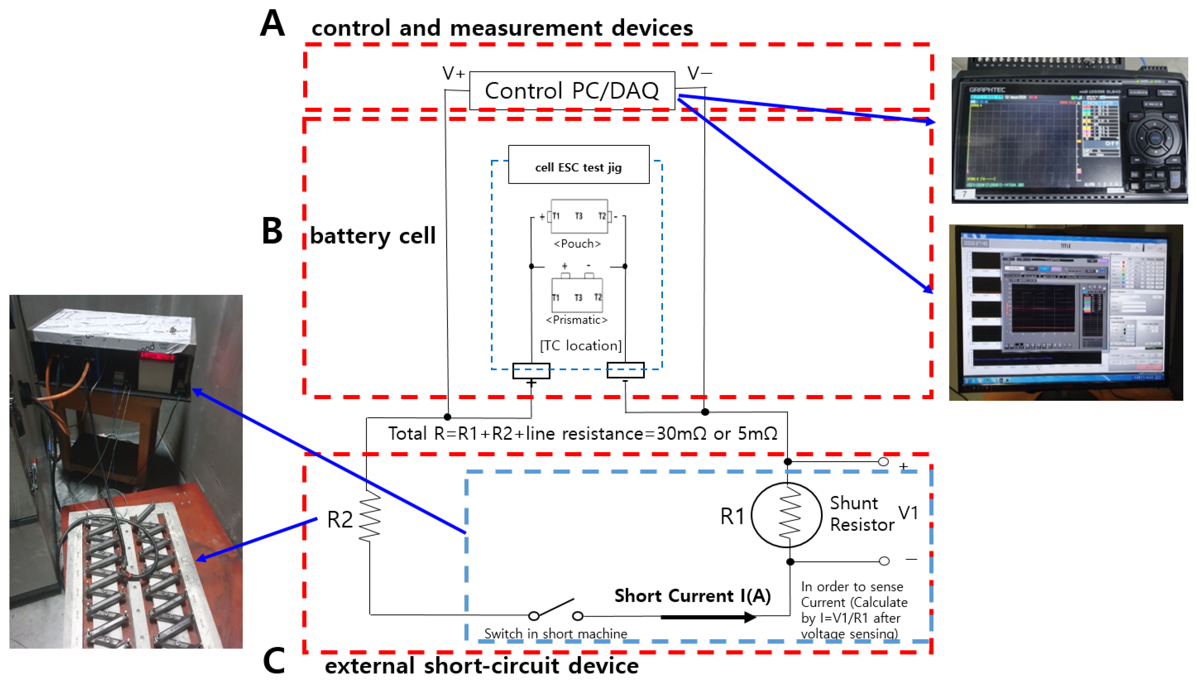
The modules for the external short-circuit test are mainly composed of two types of battery cells. Here, among the NMC series of batteries, which is the most widely used type in medium and large batteries on the domestic market, the prismatic and pouch-types are adopted in the test. This paper implements a test device for external short circuits, as shown in
Figure 2. Section A in
Figure 2 shows the control and measurement devices, which are composed of a controller for the external short-circuit device and a DAQ (data acquisition machine) for measuring the voltage, temperature, etc. Section B is the battery module, where the protection operation is performed by protection devices during a short-circuit fault. In addition, section C in
Figure 2 is the external short-circuit device, which adjusts the short-circuit resistance, measures the current and conducts short-circuit fault according to the control and measurement device.
3.2.2. External Short-Circuit Test Device for Battery Cell
The external short-circuit test for the battery cells is also performed depending on two types of battery cells. The test is classified with NMC prismatic and pouch-type batteries in series, and the test device for the external short circuit is configured as shown in
Figure 3. The test device in
Figure 3 is focused on the battery cell instead of the battery modules, as shown in
Figure 2, and the locations of the temperature measurement devices are designated according to each cell type in order to minimize the deviation of the temperature measurement.
4. Case Studies
4.1. Simulation Conditions
4.1.1. Short-Circuit Resistance Conditions
The current domestic and international standards for medium and large lithium-ion batteries are shown in
Table 1. The short-circuit resistances for ESS tests are usually higher than those for EVs. Therefore, this paper assumes short-circuit resistances of 5 mΩ and 30 mΩ, which are normally applied to battery standards for EVs and ESS, respectively.
4.1.2. Preprocessing Temperature Conditions
Preprocessing temperature is defined as the ambient temperature of the battery during charging before performing the external short-circuit test. The preprocessing charging temperature is usually set to room temperature of 25 ± 5 °C during the external short-circuit testing of battery cells in ESS that are currently applied in Korea; this is different from other applications, as shown in
Table 2. However, it is known that the severity of hazards in the battery can frequently increase by swelling due to the generation of gas inside the cell, increasing the internal pressure, if the cell is charged at high temperatures. In addition, the severity of the hazards in the battery can also be increased if the cell is charged at low temperatures, since lithium deposition occurs on the anode when the diffusion rate decreases for lithium-ions. Therefore, the external short-circuit testing of medium and large battery cells is performed after the preprocessing of charging at various temperatures such as −10 °C, 5 °C, 25 °C and 45 °C.
4.1.3. SOC Conditions
The SOC is the most important factor for the operation characteristics in external short-circuit testing. In general, most of the batteries are operated up to 100% of the SOC limit; however, the occurrence rate of fire accidents in ESS has been dramatically reduced by countermeasures of the government to operate the SOC of batteries up to 70%. Therefore, in order to evaluate the effect of the SOC in external short circuits, this paper performs tests under the SOC conditions of 70%, 80%, 90% and 100%.
All tests are performed in a thermostat device at room temperature (25 °C), and the detailed preprocess procedure of the SOC setting is illustrated in
Figure 4. The battery is charged to 100% of its capacity according to the specifications of each battery sample, as shown in section (1) of
Figure 4, and then the capacity of the battery is measured while discharging, as in section (2) of
Figure 4. Next, the battery is charged as much as the desired SOC (%) based on the measured discharging capacity, as shown in section (3) of
Figure 4. Finally, the external short-circuit test should be performed within 24 h to prevent the self-discharging voltage drop of the disused times, as shown in section (4) of
Figure 4. Furthermore, in order to eliminate the deviation for each battery sample, the rest time between charging and discharging is set to 30 min.
4.1.4. Protection Device Configurations
When the module fuse of the protection device is applied as shown in
Figure 5, which is generally used when battery cells in a battery module are in parallel connections, a large short-circuit current is rapidly increased as soon as the switch for the short circuit is closed, and then the module fuse in the large current path is operated, and the cut-off time of the module fuse is determined according to the specification of the fuse.
4.2. Characteristics of External Short Circuit Depending on SOC and Resistances
4.2.1. Characteristics of Short-Circuit Current
Regarding the pouch-type battery, the current profiles of the external short circuit are illustrated in
Figure 6, depending on the SOC and short-circuit resistance according to the test conditions. Graph ➀, ➁, ➂ and ➃ in
Figure 6 are the current profiles of the external short circuit in the case of a low short-circuit resistance of 5 mΩ, and graphs ➄, ➅, ➆ and ➇ in
Figure 6 are the current profiles in the case of a high resistance of 30 mΩ. Therefore, it is found that the magnitude of the fault current at a low short-circuit resistance of the battery cell is higher than that of a high short-circuit resistance, and the duration of the fault current at a high short-circuit resistance is shorter than that of a low short-circuit resistance. Furthermore, as the SOC values are increased, the magnitude of the short-circuit current tends to rise in the case of a short-circuit resistance of 5 mΩ and the duration of the current becomes increasingly longer at 30 mΩ.
On the other hand, the current profiles of the external short circuit in the prismatic type of battery are illustrated in
Figure 7, depending on the SOC and short-circuit resistance according to the test conditions. Graphs ➀, ➁, ➂ and ➃ in
Figure 6 are the current profiles of the external short circuit in the case of a low short-circuit resistance of 5 mΩ, and graphs ➄, ➅, ➆ and ➇ in
Figure 6 are the current profiles in the case of a high resistance of 30 mΩ. Therefore, it is found that the magnitude and duration of the current at the low short-circuit resistance is higher and shorter than the high short-circuit resistance. Furthermore, it is confirmed that the magnitude of the current in the prismatic-type battery is higher than the pouch-type battery, although the trend of the current profile in the prismatic-type battery is similar to the pouch-type battery.
Based on the presented test conditions for the pouch- and prismatic-type batteries, the maximum current characteristics of the external short circuit depending on the SOC conditions and the short-circuit resistances are shown in
Table 3. From the comparison results in
Table 3, it is confirmed that the difference of the maximum currents in both the prismatic- and pouch-types, according to the SOC of the battery, are not significant in the case of the short-circuit resistance of 30 mΩ. However, it is found that the slope of the maximum current rapidly increases depending on the SOC conditions of the battery, and the corresponding slope of the prismatic-type battery is higher than that of the pouch-type battery in the case of a short-circuit resistance of 5 mΩ.
4.2.2. Characteristics of Battery Temperature
Regarding the pouch-type battery, the temperature profiles of the external short circuit is illustrated in
Figure 8, depending on the SOC and short-circuit resistance according to the test conditions. Graphs ➀, ➁, ➂ and ➃ in
Figure 6 are the current profiles of the external short circuit in the case of a low short-circuit resistance of 5 mΩ, and graphs ➄, ➅, ➆ and ➇ in
Figure 6 are the current profiles in the case of a high resistance of 30 mΩ. Therefore, it is found that the temperature and slope of the temperature increase at a low short-circuit resistance are higher and greater than for the high short-circuit resistance. Namely, when a short-circuit resistance of 5 mΩ is applied, it is confirmed that the phenomenon of increasing temperature is caused by increasing resistance heat due to the short-circuit current; the maximum temperature among all battery samples does not exceed 90 °C, but the internal temperature is expected to exceed the measured value as the thermal conductivity of the pouch is significantly lower than the metal material.
On the other hand, the current profiles of the external short circuit in the prismatic-type battery are shown in
Figure 9, depending on the SOC and short-circuit resistances according to the test conditions. Graphs ➀, ➁, ➂ and ➃ in
Figure 6 are the current profiles of the external short circuit in the case of a low short-circuit resistance of 5 mΩ, and graphs ➄, ➅, ➆ and ➇ in
Figure 6 are the current profiles in the case of a high resistance of 30 mΩ. Therefore, it is found that the temperature of the prismatic-type battery is significantly higher than that of the pouch-type, and the slope of the increasing temperature is remarkably steep, because aluminum metal is typically used for the prismatic-type battery enclosure, which has significantly higher temperature conductivity than the pouch-type battery.
Based on the presented test conditions for the pouch- and prismatic-type batteries, the maximum temperature characteristics of the external short circuit depending on the SOC conditions and the short-circuit resistances are indicated in
Table 4. From the comparison of the results in
Table 4, it is certain that the difference in the maximum temperatures for the prismatic- and pouch-type batteries, according to the SOC conditions, is relatively small in the case of the short-circuit resistance of 30 mΩ. However, it is confirmed that the maximum temperature quickly increases depending on the SOC conditions of the battery, and the rising magnitude of the temperature in the prismatic-type battery is larger than that of the pouch-type battery in the case of a short-circuit resistance of 5 mΩ.
4.3. Characteristics of External Short Circuit with Protection Devices
Figure 10 shows the characteristics of the external short-circuit test for a battery module with cell and module fuses in the case of 30% and 100% of the SOC. Items ➀ and ➁, of
Figure 10 indicate the external short-circuit characteristics of the battery module with a cell fuse in the case of 100% and 30% of SOC, while items ➂ and ➃ of
Figure 10 are the characteristics of the battery module with a module fuse in the case of 100% and 30% of SOC, respectively. From the comparison of the results in
Figure 10, it is found that the short-circuit current is cut off in a short time by the operating module fuse, which works much faster than the cell fuse, and there are identical trends regardless of the differences of the SOC conditions and initial voltage.
In addition,
Table 5 represents the characteristics of the external short-circuit test for the protection devices and SOC conditions of the battery module. A unit of electric charge quantity (C) is adopted in order to confirm the severity of hazard for the battery cell as in Equation (1), because the measured value of the current quantity (Ah) is extremely small.
From
Table 5, it is confirmed that there is no problem with the safety of the battery since no fire or explosion, including venting, occurred for either of the module types by operating the protective device within one second of the short-circuit current. However, it is certain that the module fuse operates over 120 times faster than the cell fuse based on the same SOC conditions, and the quantity of electric charge in the module fuse is over 110 times smaller than that of the cell fuse in the case of a short-circuit fault.
4.4. Characteristics of External Short Circuit with Preprocessing Temperature
4.4.1. Characteristics of Current Depending on Preprocessing Temperature
Figure 11 shows the current profiles depending on the preprocessing temperature in the prismatic-type battery. Graphs ➀, ➁, ➂ and ➃ in
Figure 11 are the current profiles of the external short circuit under the preprocessing temperatures of –10 °C, 5 °C, 25 °C and 45 °C, respectively. From the comparison of the test results, it is found that the internal resistance in the battery sample preprocessed at 25 °C is the lowest among the samples, as the magnitude of the initial current is the largest, as shown in graph ➂ of
Figure 11. On the contrary, it is confirmed that the internal resistances in the samples preprocessed at high and low temperatures are larger, as the magnitude of the initial current is relatively low, as shown in graphs ➀, ➁ and ➃ of
Figure 11. The current profile of the battery preprocessed at 5 °C is similar at 25 °C because 5 °C is not low enough to trigger meaningful internal resistance, but 45 °C and −10 °C lead to significant variations in the internal resistance.
On the other hand,
Figure 12 shows the current profiles depending on the preprocessing temperature in the pouch-type battery. Graphs ➀, ➁, ➂ and ➃ in
Figure 11 are the current profiles of the external short circuit under the preprocessing temperatures of −10 °C, 5 °C, 25 °C and 45 °C, respectively. Therefore, it is found that the internal resistance in the battery sample preprocessed at 25 °C is the lowest among the samples, as in the prismatic-type battery, as the magnitude of the current is the largest, as shown in graph ➂ of
Figure 12. Contrastingly, it is confirmed that the internal resistances in the samples preprocessed at high and low temperatures are larger, as the magnitude of the initial current is relatively low, as shown in graphs ➀, ➁ and ➃ of
Figure 12.
4.4.2. Characteristics of Temperature Depending on Preprocessing Temperature
Figure 13 shows the temperature profiles depending on the preprocessing temperature in the prismatic-type battery. Graphs ➀, ➁, ➂ and ➃ in
Figure 11 are the current profiles of the external short circuit under the preprocessing temperatures of –10 °C, 5 °C, 25 °C and 45 °C, respectively. It is confirmed that the battery sample preprocessed at 25 °C has a lower temperature increase compared to the samples with other preprocessing temperatures, because the joule heat becomes increasingly larger due to the increase in the internal resistance during preprocessing.
On the other hand,
Figure 14 shows the temperature profiles depending on the preprocessing temperature in the pouch-type battery. Graph ➀, ➁, ➂ and ➃ in
Figure 11 are the current profiles of the external short circuit under the preprocessing temperatures of −10 °C, 5 °C, 25 °C and 45 °C, respectively. It is found that the battery sample preprocessed at 25 °C has a lower temperature increase compared to the samples at other preprocessing temperatures, because the joule heat becomes increasingly larger due to the increase in the internal resistance during preprocessing.
Table 6 shows the initial voltage, maximum current and maximum temperature in the case of an external short circuit depending on the preprocessing temperatures for the pouch and prismatic batteries. As shown
Table 6, it is confirmed that the initial voltage decreases as the internal resistance rises due to a reduction in the diffusion rates with a lower temperature during preprocessing. There is also no significant meaning for the maximum current; however, it is found that the higher or lower preprocessing temperatures are found in severe conditions, which are able to damage the battery, because the temperature of the battery increases by over 36 °C in comparison to the preprocessing temperature of 25 °C in terms of the maximum temperature.
5. Conclusions
This paper presents a test device for external short circuits, which is one of the typical safety tests, using NMC-series prismatic- and pouch-type batteries, which are the most widely used medium- and large-size batteries on the domestic market, and evaluates the characteristics of external short circuits according to diverse test scenarios such as short-circuit resistance, SOC conditions, preprocessing temperature, and protection devices. The main results of this paper are summarized as follows.
(1) From the test results for the short-circuit resistance of 30 mΩ, it is found that the variations in the magnitude of the current and temperature, depending on the SOC conditions, are insignificant and the current and temperature profiles for both the prismatic- and pouch-type batteries are similar in their trends.
(2) From the test results for the short-circuit resistance of 5 mΩ in the prismatic-type battery, it is found that the variations of the maximum current, depending on the SOC conditions at 70%~100%, are in the range of 961.9 A to 1492.1 A, and the temperatures are in the range of 173 °C to 271.6 °C. The magnitude of the maximum current and temperature are increased dramatically depending on the SOC conditions.
(3) From the test results for the short-circuit resistance of 5 mΩ in the pouch-type battery, it is found that the variations of the maximum current, depending on the SOC conditions at 70%~100%, are in the range of 1110.9 A to 1220.7 A, and the temperatures are in the range of 72.8 °C to 89.9 °C, which has similar trend to the prismatic-type battery.
(4) It is certain that the module fuse operates over 120 times faster than the cell fuse based on the same SOC conditions, and the quantity of electric charge in the module fuse is over 110 times smaller than in the cell fuse in the case of a short-circuit fault.
(5) It is found that the higher and lower preprocessing temperatures are considered severe conditions, which are able to damage the battery, because the temperature of the battery increases more than 36 °C in comparison to the preprocessing temperature of 25 °C in terms of the maximum temperature.
(6) Based on the proposed test results, it is recommended that the external short-circuit resistance should be lowered to the standards for EV batteries in order to achieve a meaningful assessment of the battery safety, as the external short-circuit resistance of ESS batteries in the current standards is too high.
Author Contributions
Data curation, M.-G.L. and B.-G.H.; Formal analysis, J.-B.J. and M.-G.L.; Funding acquisition, J.-Y.K.; Investigation, J.-Y.K. and B.K.; Methodology, J.-B.J.; Project administration, D.-S.R.; Resources, J.-B.J. and M.-G.L.; Supervision, D.-S.R.; Validation, J.-B.J., J.-Y.K., B.-G.H. and B.K.; Visualization, M.-G.L.; Writing—original draft, J.-B.J.; Writing—review & editing, B.K. and D.-S.R. All authors have read and agreed to the published version of the manuscript.
Funding
This work was supported by “Establishment of KC certifiication base for 2 MW power conversion system (PCS) for ESS” of the Korea Institute of Energy Technology Evaluation and Planning (KETEP) granted financial resource from the Ministry of Trade, Industry & Energy, Republic of Korea (No. 20209810300140).
Conflicts of Interest
The authors declare no conflict of interest.
References
- Korea Commit of Investigation for ESS Fire Accidents. A Result of Investigation for ESS Fire Accidents; MOTIE: Sejong City, Korea, 2019. [Google Scholar]
- A Korea Team of Investigation for ESS Fire Accidents. A Report of Investigation Result for ESS Fire Accidents; Korea Testing Laboratory: Jinju, Korea, 2020. [Google Scholar]
- Jung, J. A Case Study on fire accidents of ESS for safety improvement. In Proceedings of the 51th KIEE Summer Conference (2020), Busan, Korea, 15–17 July 2020; pp. 1090–1091. [Google Scholar]
- A Team of 3th Investigation for ESS Fire Accidents. A Report of Investigation Result for ESS 4 Fire Accidents; KESCO: Seoul, Korea, 2022. [Google Scholar]
- Jang, H. Study on Analysis of Fire Factor and Development Direction of Standard/safety Requirement to Keep Safety for Energy Storage System (ESS). J. Stand. Certif. Saf. 2019, 9, 25–49. [Google Scholar] [CrossRef]
- Hesse, H.C. Lithium-Ion Battery Storage for the Grid—A Review of Stationary Battery Storage System Design Tailored for Applications in Modern Power Grids. Energies 2017, 10, 2107. [Google Scholar] [CrossRef] [Green Version]
- Chen, Z. Temperature rise prediction of lithium-ion battery suffering external short circuit for all-climate electric vehicles application. Appl. Energy 2018, 213, 375–383. [Google Scholar] [CrossRef]
- Yang, R. Experimental Study on External Short Circuit and Overcharge of Lithium-ion Battery Packs for Electric Vehicles. In Proceedings of the 2020 4th International Conference on Green Energy and Applications, Singapore, 7–9 March 2020. [Google Scholar]
- Dong, T. Electrical-thermal behaviors of a cylindrical graphite-NCA Li-ion battery responding to external short circuit operation. Int. J. Energy Res. 2018, 43, 1444–1459. [Google Scholar] [CrossRef]
- Hao, J.I. Study of lithium-ion battery module’s external short circuit under diferent temperatures. J. Therm. Anal. Calorim. 2020, 144, 1065–1072. [Google Scholar]
- Lee, H. Experimental Study on the Explosion and Fire Risks of Mobile Phone Batteries. Fire Sci. Eng. 2016, 30, 111–120. [Google Scholar] [CrossRef] [Green Version]
- Exponent FA Associates. Lithium-Ion Batteries Hazard and Use Assessment; NFPA in U.S: Quincy, MA, USA, 2011. [Google Scholar]
- Balakrishnan, P.G. Safety mechanisms in lithium-ion batteries. J. Power Sources 2006, 155, 401–414. [Google Scholar] [CrossRef]
- Sim, S. Study on the Explosion and Fire Risks of Lithium Batteries Due to High Temperature and Short Circuit Current. Fire Sci. Eng. 2016, 30, 114–122. [Google Scholar] [CrossRef]
- Gao, Z. Influence of Low-Temperature Charge on the Mechanical Integrity Behavior of 18650 Lithium-Ion Battery Cells Subject to Lateral Compression. Energies 2019, 12, 797. [Google Scholar] [CrossRef] [Green Version]
- Ma, S. Temperature effect and thermal impact in lithium-ion batteries. Prog. Nat. Sci. Mater. Int. 2018, 28, 653–666. [Google Scholar] [CrossRef]
- Jung, J. Characteristics of External Short Circuit in Li-ion Battery Considering Factors of Operation and Environment. J. Korea Acad.-Ind. Coop. Soc. 2021, 22, 663–672. [Google Scholar]
- IEC Technical Committee 21. IEC 62133-2:2017; Secondary Cells and Batteries Containing Alkaline or Other Non-Acid Electrolytes—Safety Requirements for Portable Sealed Secondary Cells, and for Batteries Made from Them, for Use in Portable Applications—Part 2: Lithium Systems. IEC: Geneva, Switzerland, 2017.
- IEC Technical Committee 21. IEC 62619:2017; Secondary Cells and Batteries Containing Alkaline or Other Non-Acid Electrolytes—Safety Requirements for Secondary Lithium Cells and Batteries, for Use in Industrial Applications. IEC: Geneva, Switzerland, 2017.
- IEC Technical Committee 21. IEC 62660-2:2018; Secondary Lithium-Ion Cells for the Propulsion of Electric Road Vehicles—Part 2: Reliability and Abuse Testing. IEC: Geneva, Switzerland, 2018.
- IEC Technical Committee 21. IEC 63056:2020; Secondary Cells and Batteries Containing Alkaline or Other Non-Acid Electrolytes—Safety Requirements for Secondary Lithium Cells and Batteries for Use in Electrical Energy Storage Systems. IEC: Geneva, Switzerland, 2020.
- International Standards Organization. Electrically Propelled Road Vehicles—Test Specification for Lithium-Ion Traction Battery Packs and Systems—Part 2: High-Energy Applications; ISO: Geneva, Switzerland, 2012. [Google Scholar]
- JIS C 8714; Safety Tests for Portable Lithium Ion Secondary Cells and Batteries for Use in Portable Electronic Applications. Japanese Standards Association: Tokyo, Japan, 2017.
- SPS-C KBIA-10104-03-7312; Secondary Lithium-Ion Battery System for Battery Energy Storage Systems―Performance and Safety Requirement. Korea Battery Industrial Association: Seoul, Korea, 2018.
- UL 1973; ANSI/CAN/UL Batteries for Use in Stationary and Motive Auxiliary Power Applications. Underwrite Laboratory: Northbrook, IL, USA, 2022.
- UL 2580; Standard for Safety Batteries for Use in Electric Vehicles. Underwrite Laboratory: Northbrook, IL, USA, 2020.
- United Nations. UNECE Regulation No.100: Uniform Provisions Concerning the Approval of Vehicles with Regard to Specific Requirements for the Electric Power Train; United Nations: New York, NY, USA, 2022. [Google Scholar]
- Park, J.; Kim, B.; Kim, M.; Rho, D. A Study on the Site Acceptance Test (SAT) Evaluation Algorithm of Energy Storage System using Li-ion Battery. Acad. Ind. Coop. Soc. 2019, 20, 26–37. [Google Scholar]
- Kim, J.; Lee, H.; Tae, D.; Marito, F.; Park, J.; Rho, D. Implementation of Battery Management System for Li-ion Battery Considering Self-energy Balancing. Acad. Ind. Coop. Soc. 2020, 21, 585–593. [Google Scholar]
- Choi, I.; Han, B.; Lee, H.; Kim, K.; Rho, D. Modeling and Implementation of Movable Performance Evaluation Test Equipment for MW Scale ESS. Acad. Ind. Coop. Soc. 2020, 21, 16–26. [Google Scholar]
- Kim, Y.; Baek, S.; Kwon, Y. A Study on the Parameters Extraction Method of Cylindrical Lithium-ion Battery Cell for Electric Vehicles. Acad. Ind. Coop. Soc. 2021, 22, 609–618. [Google Scholar]
- Ryu, K.; Kim, B.; Kim, D.; Jang, M.; Ko, H.; Kim, H. A State-of-Charge estimation using extended Kalman filter for battery of electric vehicle. Acad. Ind. Coop. Soc. 2017, 18, 15–23. [Google Scholar]
Figure 1.
Fire accident cases caused by external short circuits. (a) Damage of DC contactor. (b) Burning of battery control unit.
Figure 1.
Fire accident cases caused by external short circuits. (a) Damage of DC contactor. (b) Burning of battery control unit.
Figure 2.
Configuration of test devices for battery module.
Figure 2.
Configuration of test devices for battery module.
Figure 3.
Configuration of test devices for battery cell.
Figure 3.
Configuration of test devices for battery cell.
Figure 4.
Preprocess of SOC setting for Li-ion battery’s external short-circuit test.
Figure 4.
Preprocess of SOC setting for Li-ion battery’s external short-circuit test.
Figure 5.
Operation diagram of battery module fuse by external short circuit.
Figure 5.
Operation diagram of battery module fuse by external short circuit.
Figure 6.
Current status of pouch cells during test with SOC and short-circuit resistance.
Figure 6.
Current status of pouch cells during test with SOC and short-circuit resistance.
Figure 7.
Current status of prismatic cells during test with SOC and short-circuit resistance.
Figure 7.
Current status of prismatic cells during test with SOC and short-circuit resistance.
Figure 8.
Temperature status of pouch cells during test with SOC and short-circuit resistance.
Figure 8.
Temperature status of pouch cells during test with SOC and short-circuit resistance.
Figure 9.
Temperature status of prismatic cells during testing with SOC and short-circuit resistance.
Figure 9.
Temperature status of prismatic cells during testing with SOC and short-circuit resistance.
Figure 10.
Current status of battery module during external short-circuit test.
Figure 10.
Current status of battery module during external short-circuit test.
Figure 11.
Current status of prismatic cell during testing according to preprocessing temperature.
Figure 11.
Current status of prismatic cell during testing according to preprocessing temperature.
Figure 12.
Current status of pouch cell during testing according to preprocessing temperature.
Figure 12.
Current status of pouch cell during testing according to preprocessing temperature.
Figure 13.
Temperature status of prismatic cell during testing according to preprocessing temperature.
Figure 13.
Temperature status of prismatic cell during testing according to preprocessing temperature.
Figure 14.
Temperature status of pouch cell during testing according to preprocessing temperature.
Figure 14.
Temperature status of pouch cell during testing according to preprocessing temperature.
Table 1.
Short-circuit resistances in Li-ion battery standards [
18,
19,
20,
21,
22,
23,
24,
25,
26,
27,
28,
29,
30,
31,
32].
Table 1.
Short-circuit resistances in Li-ion battery standards [
18,
19,
20,
21,
22,
23,
24,
25,
26,
27,
28,
29,
30,
31,
32].
| Items | Standards | Short-Circuit Resistances |
|---|
| Energy storage system | KBIA 10104-03 | (30 ± 10) mΩ |
| IEC 62619 | (30 ± 10) mΩ |
| IEC 63056 | (30 ± 10) mΩ |
| UL 1973 | less than 20 mΩ |
| Electric vehicle | IEC 62660-2 | less than 5 mΩ |
| ISO 12405-2 | (20 ± 10) mΩ |
| UL 2580 | less than 20 mΩ |
| UN ECE R 100 | less than 5 mΩ |
Table 2.
Temperature of charge preprocessing in standards applied to small- and large-sized batteries.
Table 2.
Temperature of charge preprocessing in standards applied to small- and large-sized batteries.
| Items | Standards | High Temperature | Low Temperature |
|---|
| Small-sized battery | IEC 62133-2 | ≥45 °C | ≤10 °C |
| KC 62133 | ≥45 °C | ≤10 °C |
| JIS C 8714 | ≥45 °C | ≤10 °C |
| Large-sized battery (ESS) | IEC 62619 | 30 °C | 20 °C |
| KC 62619 | 30 °C | 20 °C |
| KBIA 10104-03 | 30 °C | 20 °C |
Table 3.
Maximum currents during external short circuit.
Table 3.
Maximum currents during external short circuit.
| | Max Current (A) |
|---|
| SOC Condition | 70% | 80% | 90% | 100% |
|---|
| Prismatic | 5 mΩ | 961.9 | 1111.2 | 1230.5 | 1492.1 |
| 30 mΩ | 347.9 | 354.3 | 356.5 | 356.5 |
| Pouch | 5 mΩ | 1110.9 | 1133.2 | 1186.6 | 1220.7 |
| 30 mΩ | 322.3 | 332.0 | 344.6 | 346.7 |
Table 4.
Maximum temperatures during external short circuit.
Table 4.
Maximum temperatures during external short circuit.
| | Max Temperature (°C) |
|---|
| SOC Condition | 70% | 80% | 90% | 100% |
|---|
| Prismatic | 5 mΩ | 173.0 | 182.9 | 236.2 | 271.6 |
| 30 mΩ | 38.0 | 43.5 | 45.5 | 45.4 |
| Pouch | 5 mΩ | 72.8 | 76.4 | 84.2 | 89.9 |
| 30 mΩ | 53.7 | 53.9 | 53.3 | 53.0 |
Table 5.
Characteristics of battery module’s external short-circuit test according to protection device and SOC.
Table 5.
Characteristics of battery module’s external short-circuit test according to protection device and SOC.
| Items | Initial Voltage (V) | Cut-Off Time (ms) | Quantity (C) |
|---|
| Module fuse | SOC 30% | 50.84 | 7.79 | 18.00 |
| SOC 100% | 59.31 | 3.84 | 16.51 |
| Cell fuse | SOC 30% | 61.00 | 888.63 | 2842.99 |
| SOC 100% | 66.33 | 491.98 | 1850.75 |
Table 6.
Characteristics of external short circuit with preprocessing temperature.
Table 6.
Characteristics of external short circuit with preprocessing temperature.
| Items | Preprocess Temperature (°C) | Initial Voltage (V) | Maximum Current (A) | Maximum Temperature (°C) |
|---|
| Prismatic | −10 | 4.044 | 274.6 | 82.0 |
| 5 | 4.078 | 341.8 | 64.7 |
| 25 | 4.084 | 356.5 | 45.4 |
| 45 | 4.082 | 313.7 | 80.3 |
| Pouch | −10 | 4.110 | 339.4 | 60.4 |
| 5 | 4.150 | 283.2 | 79.9 |
| 25 | 4.170 | 346.7 | 53.0 |
| 45 | 4.176 | 297.3 | 83.6 |
| Publisher’s Note: MDPI stays neutral with regard to jurisdictional claims in published maps and institutional affiliations. |
© 2022 by the authors. Licensee MDPI, Basel, Switzerland. This article is an open access article distributed under the terms and conditions of the Creative Commons Attribution (CC BY) license (https://creativecommons.org/licenses/by/4.0/).


 ,
, 


