Article

Study on a Two-Dimensional Supersonic Inlet with Inner Profile Adjustment

1
School of Power and Energy, Northwestern Polytechnical University, Xi’an 710072, China
2
School of Aerospace Engineering, Huazhong University of Science and Technology, Wuhan 430074, China
*
Author to whom correspondence should be addressed.
Energies 2022, 15(14), 5057; https://doi.org/10.3390/en15145057
Submission received: 23 May 2022 / Revised: 6 July 2022 / Accepted: 7 July 2022 / Published: 11 July 2022

Abstract

:
According to the requirements of a wide speed range, a variable-geometry supersonic inlet with inner surface adjustment is studied. The basic design model of the inlet is established, and the influence of profile adjustment on the resisting back pressure ability and inlet performance boundary are analyzed using a theoretical method. Based on the numerical simulation method, the flow field simulation is carried out, and the flow field parameter distribution and performance of the adjustment inlet are studied in comparison with the fixed-geometry scheme. The results show that the starting Mach number is not changed for two inlet schemes because they have the same profile during low-speed flight. The fixed-geometry inlet has insufficient compression on the incoming flow, and the resisting back pressure ability decreases significantly during high-speed flight. The compression ratio and the compression wave system can be easily changed at the same time through the adjustment of the inner profile for the adjustable inlet during high-speed flight. Both the theoretical analysis and numerical simulation show that the resisting back pressure ability and performance are significantly improved after the adjustment. As such, the adjustment method in this paper can fundamentally solve the problem of the insufficient compression of the wide-range working inlet during high-speed flight, and the method can be easily realized.

1. Introduction

The fixed-geometry inlet, which is widely used in narrow flight speed range aircraft such as the supersonic cruise missile, has a simple profile structure. As the flight speed range increases, it is difficult to coordinate the low-speed starting performance and the high-speed cruising performance of the ramjet, which seriously restricts the engine performance improvement [1]. In order to improve the inlet performance, many studies have been carried out on various active and passive flow control methods, such as boundary layer suction [2,3], plasma [4,5,6], vortex generators [7,8,9,10], and so on. These flow control methods could improve the shock wave/boundary layer interference and other flow field characteristics, and improve the inlet performance to a certain extent. However, these technical means cannot fundamentally solve the problem of the insufficient compression of the wide-speed inlet in high-speed flight. Moreover, with the change of the incoming flow speed and the migration of the shock wave system, the position of the shock wave/boundary layer interference changes, the flow control device cannot adapt to a wide speed range effectively.
Variable-geometry is an effective technical method to realize wide-speed-range flight. Many variable-geometry schemes have been studied for different forms of the inlets. The axisymmetric inlet usually adopts the moving centrosome scheme, and the air compression performance can be adjusted through the cooperation of the centrosome shape, such as the GTX inlet [11], SR-71 inlet [12], SABRE inlet [13], ATREX inlet [14] and so on. A lot of research on the flow field characteristics and performance laws has been carried out for the axisymmetric inlet [15,16]. The adjustment of the two-dimensional inlet is mainly realized by the translation or rotation of the supersonic compression surfaces, such as the French PROMETHEE inlet [17] and the USA Strutjet inlet [18]. There are other methods, such as the lip both translation and rotating variable-geometry inlet [19], the sidewall compression inlet adjustment with the lifting strut [20], a rigid structure rotation/translation scheme [21], and so on. Zhang [22] studied a two-dimensional variable-geometry inlet. The first stage of the inlet is curved compression, and the second compression wall extends to the throat and rotates around a fixed hinge. Liu [23] studied a variable-geometry assisted restart method for a high-Mach-number inlet, which changes the contraction ratio by rotating the cowl to realize the restart process. Liu [24] proposed a dual-channel RBCC variable-geometry inlet, which can realize the conversion between low-speed and high-speed configurations by rotating part of the compression surface. Dou [25] developed a control method for an air-breathing hypersonic vehicle with a variable-geometry inlet; in the variable-geometry inlet, a movable translating cowl is used to track the shock on the lip conditions in order to capture enough air mass flow. In addition, the French ONERA Research Center and the MBDA proposed the variable-geometry engine scheme LEA for hypersonic vehicles, which adopts the wall surface horizontal sliding adjustment method [26]. This two-dimensional inlet adjustment method is similar to the axisymmetric variable-geometry adjustment method. These schemes are usually more complex in the implementation structure.
In this paper, a supersonic inlet with internal surface adjustment is studied. Through the cooperation of the internal surface slider and the basic surface, the joint adjustment of the compression surface and throat height is realized through simple horizontal movement. Unlike the traditional compression surface adjustment scheme, the profile adjustment is carried out in the inner channel. By changing the length of the compression surface and increasing the number of shock waves during high-speed flight, the enhanced compression of the incoming flow is realized. At the same time, the adjusting mechanism has no rotating parts, which simplifies the adjusting mechanism. For variable-geometry schemes, an inner-profile adjustable method is put forward for a wide-flight-speed inlet, and the matching design method of the throat and the diffuser is studied. The flow channel is changed by the translation of the inlet’s inner surface with the horizontal direction. The theoretical method is used to analyze the inlet performance boundary, while numerical simulation is used to study the flow field change mechanism and performance laws during the adjustment process.

2. Inlet Model

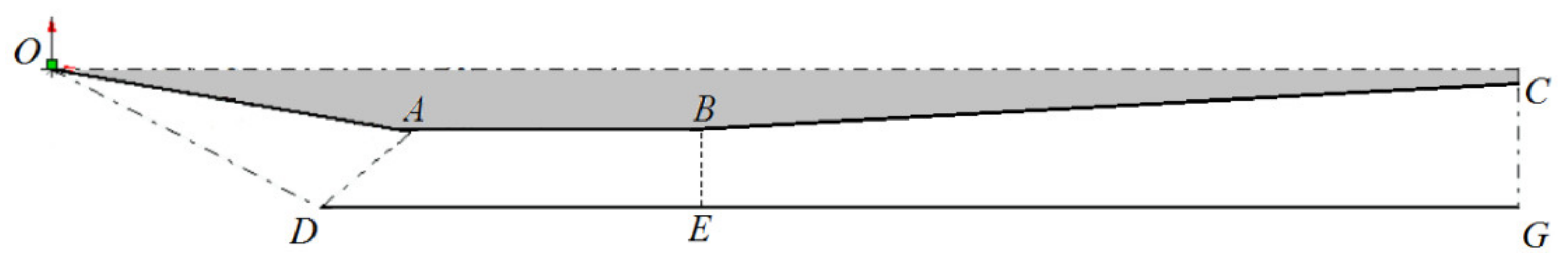
2.1. Fixed-Geometry Inlet Scheme

The fixed-geometry inlet (shown in Figure 1) adopts three shock wave compression schemes, and includes a supersonic compression section (from point O to point A), an iso-straight throat section (from point A to point B) and a subsonic diffuser section (from point B to point C). In the design state, the first-order oblique shock OD and the reflected shock DA constitute the oblique shock system. The length of the iso-straight section AB is twice the height of the inlet throat, in order to weaken the reflected shock wave system after the oblique shock DA at the design point.

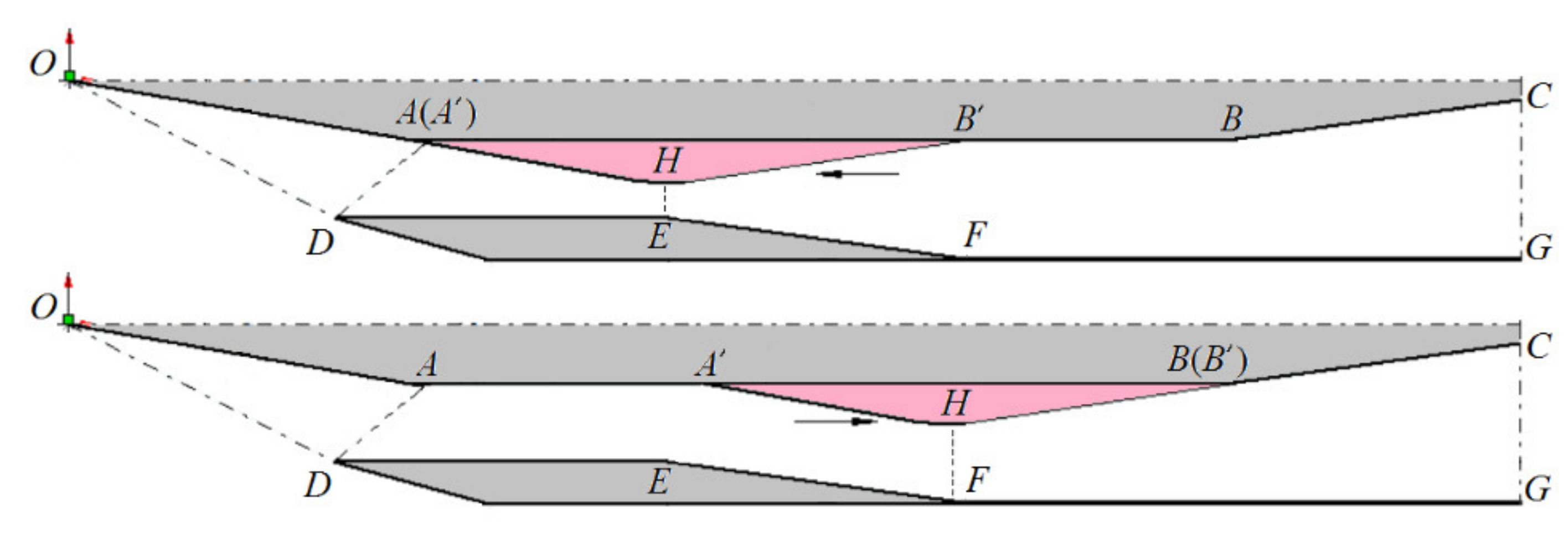
2.2. Adjustable Inlet Scheme

The adjustable inlet, shown in Figure 2, has the same external compression profile as the fixed-geometry inlet, i.e., the same coordinates of point A and point D compared with point O. The coordinates of point C and point G compared with point O are the same for the two inlet schemes here. As such, the adjustable inlet and the fixed-geometry inlet have the same length and the same throat height during low-speed flight.
The inlet adjustment principle of the sliding block moving in the inner flow channel is shown in Figure 2. The basic inlet profile is designed according to the low-speed flight state. The upper wall OABC and the lower wall DEFG are fixed structures. The sliding block A′B′H is a rigid-body structure, and the geometric shape is approximately triangular, and can slide along the section AB of the upper wall.
During a high-speed cruise flight, the sliding block A′B′H slides forward horizontally, and the relative positions of point H and the EF change, which could reduce the throat area. When the leading edge point A′ of the sliding block A′B′H coincides with the end point A of the inlet external compression surface, the throat becomes HE, and the inlet’s upper compression surface is extended from OA to OAH. During low-speed flight, the sliding block moves backward horizontally, the throat evolves into HF, and its height increases. At the same time, the first-stage compression surface becomes OA, and the internal compression channel is composed of AA′H and DEF. HB′ is collinear with the BC. HB(B′)C and FG constitute an expansion channel.
In the above model, on the one hand, through the horizontal movement of the sliding block, the geometry of the inner channel is adjusted, the throat height and position are changed, and the compression ratio is changed too. On the other hand, the length of the inlet compression surface also changes. During the adjustment process, the sliding block undertakes the function of compressing and expanding.

2.3. Design Parameters

It is necessary to coordinate the base inlet surface and the sliding block shape while considering the air compression effect under different flight speeds, and whilst avoiding the occurrence of a strong shock/boundary layer interference, which will adversely affect the flow field performance seriously.
The basic profile of the adjustable inlet is a fixed geometric structure, which is designed according to the low-speed starting requirement and the high-speed working conditions. As shown in Figure 3, the basic profile is a three-wave system, and the first-stage compression angle δ1 is designed to ensure the inlet’s normal operation in low-speed flight. Taking flight speed Ma 2.0 as an example, the δ1 could be 10°, according to the inlet design theory [27].
According to the Equation (1), the flow rate m ˙ D of the inlet at the design point can be calculated:
m ˙ D = ϕ D K m A D P D * T D * q λ D
Among them, T D * and P D * are the total temperature and total pressure of the free flow at the design point, respectively; A D is the capture area of the inlet; K m is a constant, for air, K m = 0.0404 s m 1 K 1 / 2 ; and ϕ D , λ D and q λ D are the flow coefficients, dimensionless velocity coefficient, and flow function, respectively, calculated according to the following formula:
ϕ D = A A D λ D = V D c cr q λ D = k + 1 2 1 k 1 λ D 1 k 1 k + 1 λ D 2 1 k 1
Here, A , V D , c cr and k are the cross-sectional area of the far front pre-inflow pipe, the air velocity at the design point, the critical velocity, and the adiabatic exponent of air, respectively.
By transforming Formula (1), the capture height H 2 of the inlet can be calculated according to the design point parameters T D * and P D * , the flow rate m ˙ D and the inlet width W 2 :
H 2 = m ˙ D T D * ϕ D W 2 K m P D * q λ D
The outer contour height H 1 of the inlet is calculated in the following way:
H 1 = H 2 + L 7 tan δ 4 + Δ H
In the above equation, Δ H is the wall thickness of the inlet.
In the design of this paper, the angle δ 2 of the slider is consistent with the first-stage compression angle, that is, δ 2 = δ 1 . The values of δ 3 and δ 4 determine the profile change of the expansion section. In order to ensure the continuous profile of the subsonic expansion section during high-speed flight, take δ 3 = δ 5 . R is the value of the fillet radius between the two faces of the slider, as shown in Figure 3.
The position of the inlet lip point B is determined according to the first-order shock angle δF and the geometric relationship under the first-order shock sealing condition:
x D = H 2 / tan δ F y D = H 2
Point A is determined by the relationship of the second-order shock wave and the inlet lip point B. Assuming the second shock wave angle is δS2, the coordinates of point A are
x A = H 2 + x D t g δ S 2 δ 1 t g δ 1 + t g δ S 2 δ 1 y A = x A t g δ 1
After determining the coordinates of point A, the corresponding throat height can be obtained:
H 3 = H 2 y A
The flow compression and profile coordination should be considered in the sliding block shape design. As shown in Figure 2, OA and A′H are collinear at high speeds, and there are:
δ 1 = δ 2
In the scheme design above, the adjustable range of the distance x, that from the leading edge to the sliding block center, is as follows:
x L 6 , L 1 + L 2
In addition, there is a geometric relationship:
L 1 + L 2 = L 6 + L 7
When the leading edge of the sliding block changes, the variation rule of the throat height is
H T h = H 2 L 3 tan δ 2 + x L 6 tan δ 4
With the throat height changing, the corresponding inlet compression ratio changes as follows:
ε = H T h / A
Taking derivatives on both sides of the Equation (11):
d H T h d x = tan δ 4
Therefore, in the adjustment process above, the inlet throat height changes linearly with the distance x.
The main profile parameters are listed in Table 1.

3. Theoretical Analysis and Numerical Method

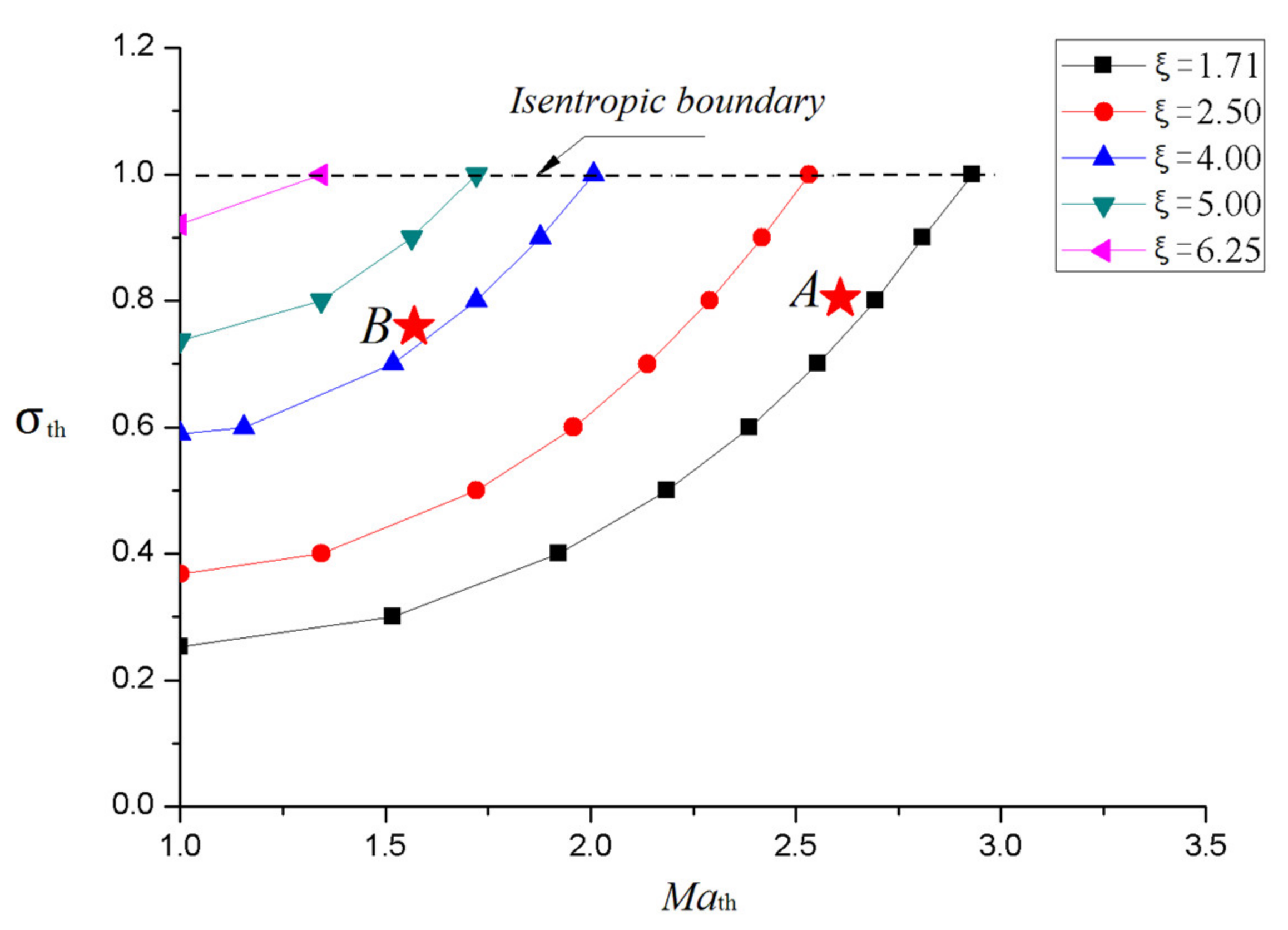
3.1. Resisting Back Pressure Ability

The ability to resist back pressure is an important performance parameter for the supersonic inlet. The insufficient compression of the inlet or severe shock/boundary layer interference between the positive shock and the fully developed boundary layer will have an important impact on the ability to resist back pressure.
In the supersonic inlet diffuser, for shock/boundary layer interference, there is a complex shock wave system composed of multiple oblique shock waves and the boundary layer separation, which will move forward as the back pressure increases.
Theoretically, under the critical working state, the positive shock wave is located at the throat. The relationship between the outlet parameters and throat parameters is as follows:
q λ out = A out A th q λ th
where A th , A out , q λ th and q λ out are throat area, outlet area, throat flow function and outlet flow function, respectively. Combined with Equation (2) and the relationship between the parameters before and after the normal shock wave, the parameters of the outlet in the critical state can be calculated from the throat parameters
The separation parameters in the viscous flow are calculated based on the empirical equation used in the expansion nozzle [28]:
P i P a = 2 3 P a P c 0.2
where Pi is the pressure at the separation point, Pa is the local pressure, and Pc is the coming flow’s total pressure. The diffuser’s back pressure calculation is equivalent to the process of solving the outlet pressure under the inlet’s critical state, taking the expansion ratio of the subsonic diffuser as the separation expansion ratio. In the expansion section of the inlet, Pa in Equation (14) is the diffuser’s exit pressure Pout. Pc is the total pressure at the diffuser entrance, that is, the total throat pressure P*th of the inlet.
The Equation (14) will change into following form:
P out = 3 2 P th P th * 0.2 1 1.2
where Pth is the throat’s static pressure. The average parameters of the throat could be gained according to the inviscid viscous shock wave system theory and the inlet 3D numerical simulation, respectively. Then, the diffuser’s exit pressure ratio could be calculated.
According to the equation above, it can be seen that the improvement of the resisting back pressure ability of the inlet can be achieved by increasing the throat’s static pressure Pth and the throat’s total pressure P*th.
Before the throat, the pressure ratio πi, can be calculated as follows:
P th = i = 0 m π i P
where m is the number of the shock before the throat, and P is the inlet’s coming flow static pressure.
The throat pressure Pth can be increased by increasing the compression angle to increase the pressure ratio πi of each shock wave, or by increasing the number of compression shock waves. For the scheme in Figure 2, during high-speed flight, compared to the fixed-geometry scheme, the inlet compression surface after the profile adjustment is extended to OAH. Although the compression angles of the inlet remain unchanged, the number of shock waves in the inner flow channel will increase with the shock reflection. Increasing the number of shock waves will reduce the P*th, but the static pressure Pth will increase faster, which can effectively improve the inlet’s resisting back pressure ability.
The throat’s total pressure P*th and static pressure Pth are obtained from numerical simulation. The critical pressure ratio Pout/P is calculated using Equation (15). The results of the three parameters above are shown in Table 2. It can be seen that the critical pressure ratio Pout/P at Ma 2.0 is close between the fixed geometric scheme and the adjustable scheme. Compared with the fixed geometric scheme, the throat’s total pressure P*th of the adjustable scheme slightly decreases at Ma 3.5, but the throat’s static pressure Pth increases by 4.31 times, and the back pressure ratio of the critical state is significantly improved from 7.13 to 23.86. Here, ξ is the inlet compression ratio.

3.2. Total Pressure Recovery

The inlet is divided into two sections: before and after the throat. After the airflow passes through the shock waves before the throat, the total pressure recovery σi can be calculated as follows:
σ th = i = 0 m ( σ th i )
Here, σith is the total pressure recovery of each shock wave.
After the shock waves, the throat Mach number is Math. According to the continuity equation, the relationship between the inlet compression ratio ξ, the throat Mach number Math and the total pressure recovery σth is
ξ = A A th = ϕ σ th q M a th q M a
Equation (19) shows that when the compression ratio ξ is constant, the throat Mach number Math has a corresponding relationship with the total pressure recovery σth.
Figure 4 is the corresponding relationship between the throat Mach number Math and the total pressure recovery σth with different compression ratio ξ.
It can be seen that there is a correlation between the throat Mach number Math and the total pressure recovery σth at a certain compression ratio ξ. The higher the throat Mach number Math, the weaker the compression of the incoming flow, and the higher the total pressure recovery σth.
Regardless of the viscous boundary layer loss, there are upper and lower inlet performance boundaries with the different compression ratios ξ. The upper boundary is the isentropic compression boundary, that is, there is no loss in the compression process, and the throat velocity Math is the highest. The left boundary is the compression boundary, where Math = 1.0, and this boundary indicates the strongest compression of the incoming flow.
Figure 4 shows that the closer to the upper left corner of the region, the lower the throat Mach number Math, and the higher the total pressure recovery σth, the better the compression of the flow, and the larger the corresponding compression ratio ξ.
The state of the supersonic airflow after compression is dominated by the physical process of the shock wave system. The iso-compression ratio ξ curves show that the smaller the compression loss of the shock system, the higher the total pressure recovery σth.
In Figure 4, the characteristic points A and B of the fixed-geometry inlet and the adjustment inlet are given, which are marked with the symbol “★”. The corresponding compression ratios of point A and point B are 1.791 and 4.0, respectively. It can be seen that the state B is closer to the left boundary, that is, the compression of the supersonic airflow is strong, the flow speed front of the normal shock is reduced, and the inlet performance is better.
Due to the complex interference flow between the normal shock wave and the boundary layer in the viscous flow field, the flow loss is difficult to analyze accurately using a theoretical method, and the numerical simulation should be used to study further.

3.3. Numerical Method and Boundary Conditions

Write the Reynolds-averaged N-S equation as a vector integral over any control volume V [29]:
t V W d V + F G d A = V S d V
where the vectors are respectively defined as
W = ρ ρ u ρ v ρ w ρ E ,   F = ρ u ρ u u + p i ^ ρ u v + p j ^ ρ u w + p k ^ ρ u E + p u ,   G = 0 τ x i τ y i τ z i τ i j v j + q
In Equation (20), S represents the source term, which is taken as zero in this paper. i ^ , j ^ and k ^ are the three coordinate base vectors of the Cartesian coordinate system, respectively. u is the velocity vector; u , v and w are its components along the three coordinates, respectively; and q is the heat flux related to thermal conduction.
Based on the finite volume method, the diffusion and convection terms in the governing equations are discreted by the second-order central difference scheme and the second-order upwind scheme, respectively, and the coupled implicit solution method is used to solve the governing equations.
In the supersonic flow field, the shock boundary layer/interference is a very important flow phenomenon, and the turbulent flow model is very important for the simulation of the separation flow process. According to the reference study [30], this paper adopted the SST K-ω turbulence model, which has good predictive ability in separation flow with a high adverse pressure gradient.
The boundary conditions of the numerical model include the pressure far field, pressure outlet, and wall, etc. The front and side of the external flow field are the pressure far field boundaries, and the pressure, temperature and Mach number of the incoming flow are set. In the calculation model of this manuscript, the flight altitude is 10 km, the incoming flow pressure and temperature are 26,436 Pa and 223.15 K respectively, and the flight Mach number is given in Section 4. The export of the inlet and the outlet of the external flow field are both pressure outlet boundaries. The export pressure of the inlet is set according to the back pressure calculation conditions, while the outlet pressure of the external flow field is set as the static pressure of the incoming flow; the inner and outer walls of the inlet are all adiabatic wall conditions, and no parameter setting is required.
Structured grids are generated for the entire computational domain, and densification is performed in areas such as the shock/boundary layer interference, separation, and near-wall surfaces. For the inlet model in this paper, a 2D computing grid was generated, the number of the computational grid was about 360,000, and the near-wall y+ was not greater than 2.

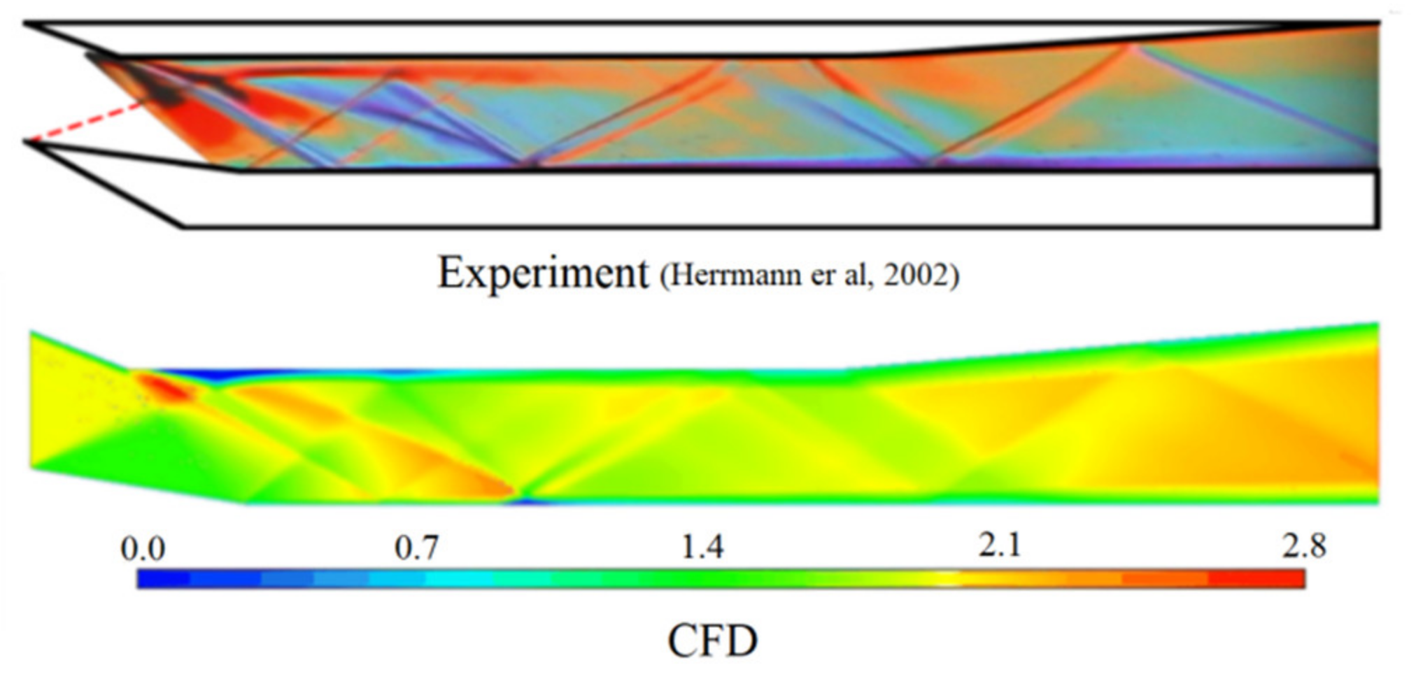
3.4. Verification of the Numerical Methods

The numerical simulation verification was carried out with the inlet model in the reference [31], which is often used to verify numerical simulation methods by inlet researchers [32].
The model in the reference [31] was divided into 320,000 calculation grids in this paper, and the calculation conditions were consistent with the experimental conditions; namely, the incoming flow velocity was Ma2.41, the total temperature was 295 K, and the total pressure was 0.569 MPa.
Comparing the wall pressures calculated by the numerical simulation with the experimental results in Figure 5, it can be seen that the numerical simulation results are in good agreement with the experimental results. Because there is a complex shock wave system including the shock wave and expansion wave in the inlet, the pressure on the upper and lower walls fluctuated many times. Along the flow direction, the numerical results of the lower wall were consistent with the experimental results, and the pressure showed three major jumps. Due to local expansion, a sudden drop occurred after the high pressure of the first stage, and then there were two fluctuations. The numerical calculation is in good agreement with the experimental values. In general, the numerical calculation can better reflect the location and process of pressure fluctuation caused by a shock wave in the inner channel.
The numerically simulated Mach number distribution is compared with the experimental schlieren in Figure 6. It can be seen that the distribution of the shock wave system obtained by numerical calculation is close to the experimental schlieren. The shock wave reflected by the lower lip, the expansion waves at the turning point of the upper wall, the local separation near the upper wall, and the shock wave reflection in the inner flow channel can be correctly reflected in the numerical calculation.
Through the comparison of the above results, under the same modeling method and calculation strategy, the pressure distribution and schlieren comparison show that the modeling method in this paper is feasible, and that it can correctly calculate the flow field of a supersonic inlet with a complex flow process.

4. Inlet Flow Field and Performance Research

4.1. Results and Analysis in a Low-Speed Self-Starting Mach Number State

In the inlet self-starting Mach number simulation calculation study, the flow field is initialized from the incoming flow Mach number 1.8, then the incoming Mach number is gradually increased until the inlet can start normally and a complete shock wave system is established. The calculation shows that two inlet schemes here can start normally when the incoming flow Mach number is increased to 2.2, that is, the inlet self-starting Mach number is 2.2, which is higher than the isentropic limit value.
When the leading edge of the back pressure reaches the trailing edge of the iso-straight throat section, the back pressure arrives at its maximum value, and the inlet is in the critical state. For the two inlet schemes, the flow field under the critical state is calculated respectively, and the Mach number distribution is shown in Figure 7. In the figure, S represents the shock wave, R represents a specific region, and the subscript is the number of different shock waves or regions.
The inlet lip is designed according to the first-order shock wave seal at Ma = 3.0. At the self-starting Mach number, the oblique shock wave S1 generated by the compression surface falls outside the inlet lip. The shock wave S2 generated by the inlet lip incident behind the turning point of the upper wall and several reflection shock waves are generated in the throat section.
In the fixed-geometry inlet, under the action of the back pressure, the normal shock wave approaches the leading edge of the diffuser, and a large-scale separation flow phenomenon occurs near the upper wall of the diffuser. The separation zone develops from the leading edge of the diffuser to its exit. The flow velocity in the throat is about Ma1.6, and the ending normal shock wave SN is a typical “x”-type shock wave system. The local separation area induced by the shock wave/boundary layer interference is small due to the low velocity before the normal shock. The main flow is constrained near the lower wall by the upper separation, and the parameter distribution of the main flow is relatively uniform.
In the adjustable inlet, the compression wave system before the throat is similar to the fixed-geometry inlet, and the normal shock wave also exhibits as an “x” shape. The length of the diffuser is reduced due to the change of the geometric profile, the range of the separation zone R2 is small, and the leading edge reaches the point H (Figure 2). From the Mach number contours shown in Figure 7, a local separation appears near the upper-wall turning point A due to the interference of the shock wave S2 and the upper-wall boundary layer, but the separation area is small. The wave system S2-1 in the throat is the coupling of the reflected shock wave and the expansion wave, and then the shock wave system S2-2 is generated by the reflection. The sliding block surface turns downward at point A′, where the normal shock wave is located. Near point A on the upper wall and point E on the lower wall, two local separations are induced by the shock waves, which cause the boundary layers to thicken. In the AH section, the shock wave systems Sn-1, Sn-2 and Sn-3 continue to be generated, and the separation on the upper wall develops to point H.
From the pressure comparison in Figure 7c,d, the static pressure and total pressure distribution in front of the throat at Ma2.2 are the same for the two schemes. Because the back pressure of the adjustable inlet is slightly higher, the pressure in the expansion section of the inlet is higher than that of the fixed inlet. Due to the flow separation in the expansion section, the total pressure in the main stream is high and the total pressure in the separation zone is low. In general, the pressure distributions of the two schemes show little difference at low speeds, and the expansion section pressure of the adjustable inlet is slightly higher.
The performance parameters of the two inlet schemes are compared in Table 3. It can be seen that the parameters of the two schemes are different at the self-starting Mach number 2.2. Although the compression ratio of the two configurations is the same, due to the geometric matching design, the length of the throat section in the adjustable scheme increases; especially, the AH section produces additional compression, such that the throat velocity Math is lower. The overall performance is slightly higher than that of the fixed geometric scheme, and the resisting back pressure ability is also improved. There is little difference in the throat pressure ratio Pth/P between the two inlet schemes. In addition, comparing the back pressure ratio Pout/P calculated by the numerical simulation with the theoretical calculation results in Table 2, it can be seen that there are little differences in these parameters.

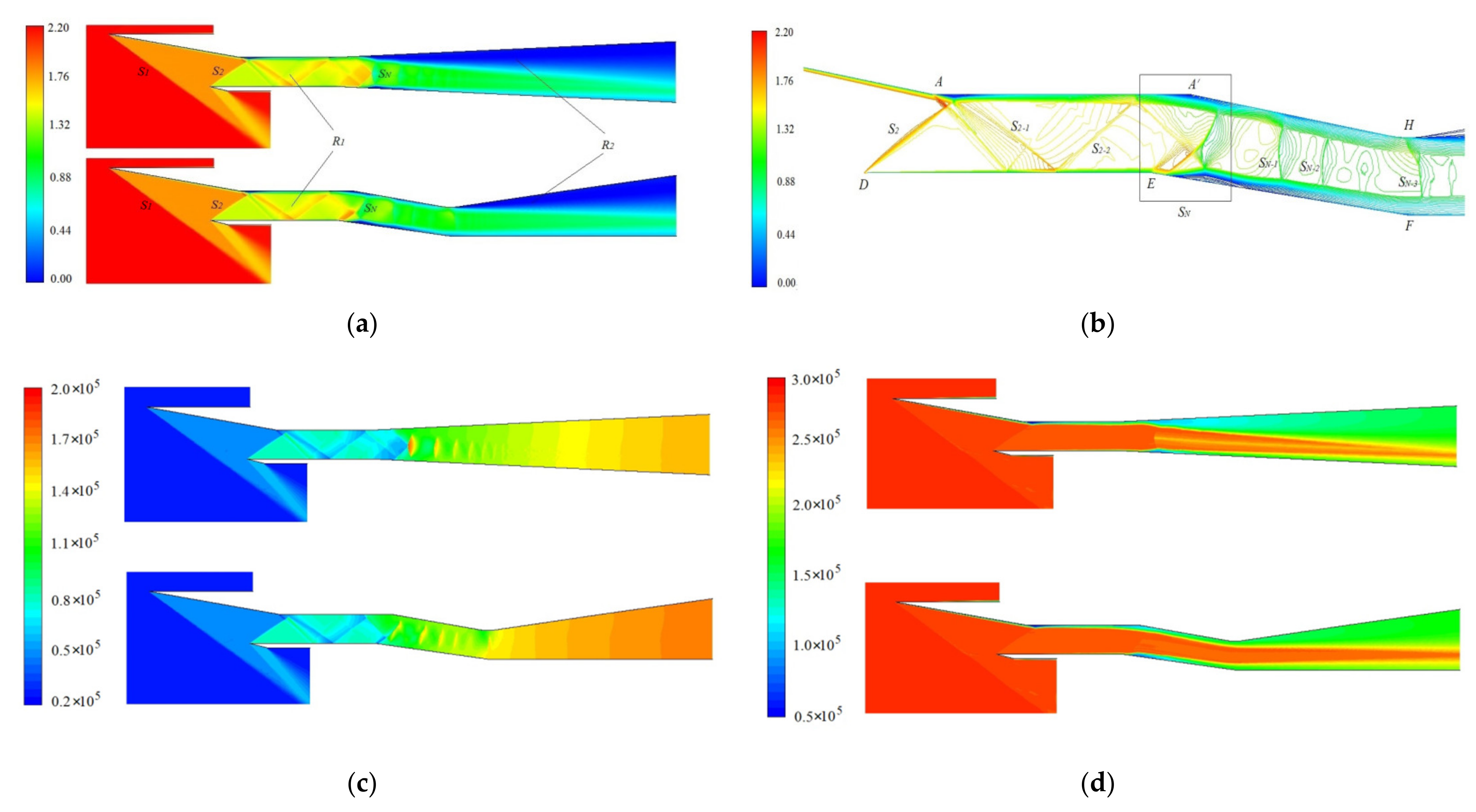
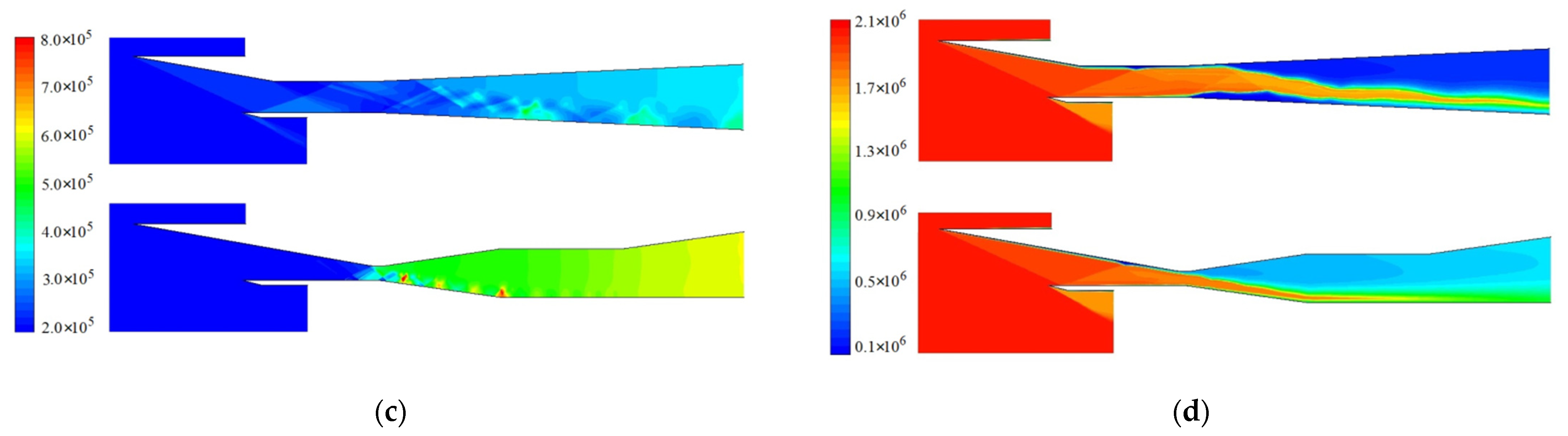
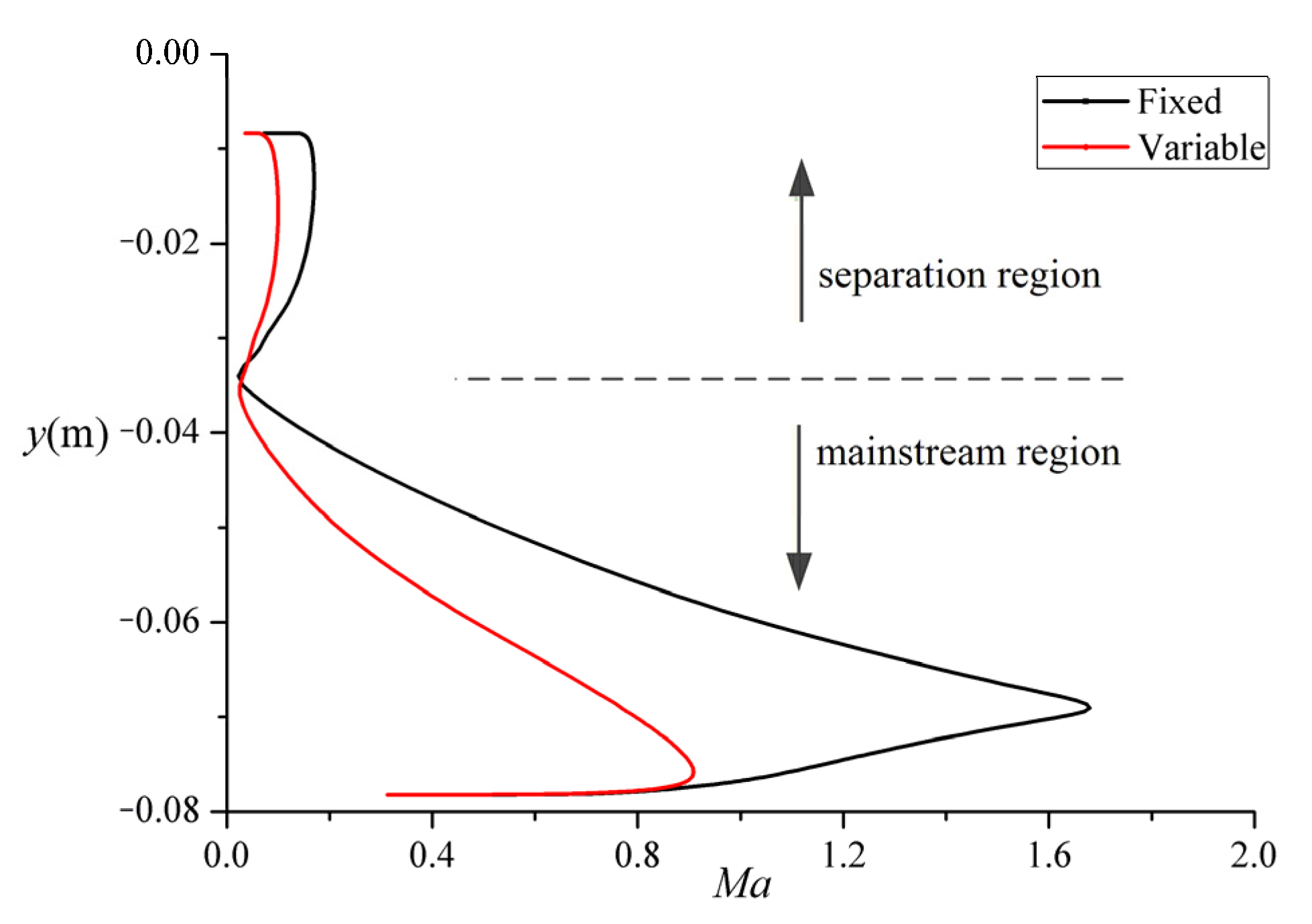
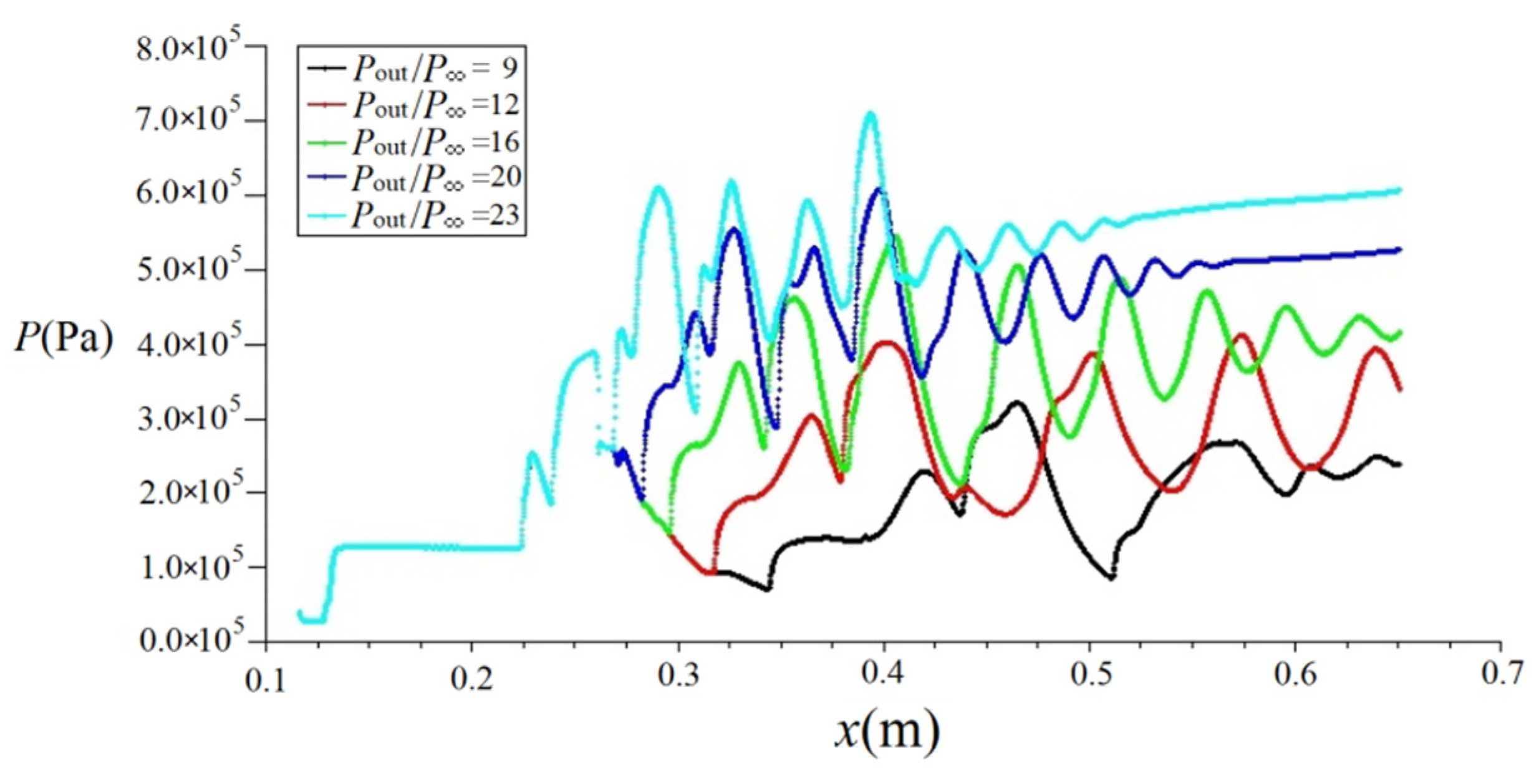
4.2. Results and Analysis at High-Speed Cruise State

The numerical simulation results of the fixed-geometry inlet and the adjustable inlet are compared in the high-speed cruise state Ma 3.5, as shown in Figure 8. The definitions of parameters S and R are the same as those in Figure 7.
In the fixed-geometry inlet, the first shock wave S1 incident location is behind point D of the inlet lip at Ma 3.5. Due to the flight velocity increase from Ma 2.2 to Ma 3.5, the shock angle decreases, and the reflected shock wave S2 incident location is after the upper-wall turning point A. Larger expansion appears near point A. The expansion wave system intersects and reflects the shock wave system in the throat section. The flow Mach number in the throat is higher, and the main flow velocity increases to about Ma 2.8.
At higher throat Mach numbers, normal shocks evolve into oblique shocks. From the numerical simulation results, it can be seen that the upper wall separation R2 is very large, and it develops from the leading edge of the diffuser to its exit. Due to the strong shock wave/boundary layer interference on the lower wall, local separation occurs, and its length is large too. When the back pressure is 9.0 times to the incoming flow pressure, the inlet is already in the critical state, and further increasing of the back pressure will cause the shock wave system to enter into the throat section, which could result in shock wave oscillation and the inlet’s unstable working.
The flow field Mach number distribution of the adjustable inlet in Figure 8 shows that the sliding block moves to the leading edge of the inlet’s inner wall, the compression surface OA is collinear with the surface A′H of the sliding block, which is equivalent to extending the compression surface to the throat HE. The inlet compression ratio increases from 1.791 of the fixed-geometry inlet to 4.0. Due to the extension of the compression surface, although the compression surface still has only one slope of OH, the shock wave is reflected back and forth in the diffuser. The relative compression angle of each shock wave is 10°, and at least four reflected shock waves are generated in the compression section. Because the shock wave intensity is not high, there is no obvious boundary layer separation in the compression section. The incoming flow is compressed by four shock waves, and the flow average velocity is reduced to Ma1.57 when it reaches the throat, which significantly increases the supersonic compression efficiency. Due to the low flow velocity in the throat section, the normal shock wave system is weakened relative to the fixed-geometry inlet, and no obvious separation is generated near point E. The large-scale separation on the upper wall is forwarded to point H, and the main flow is confined near the lower wall by the separation area R2.
In the adjustable inlet, the decrease of the throat Mach number weakens the interference between the positive shock wave and the boundary layer, which is conducive to reducing the unsteady flow process in the separation zone after the shock wave. The unsteady characteristics of the expansion section of the adjustable inlet need to be further studied.
Comparing the pressure contours at Ma 3.5, the static and total pressure distributions in front of the throat of the two inlets are consistent, but the expansion section is very different. Because the back pressure of the adjustable inlet is much higher than that of the fixed inlet, the static pressure in the expansion section also increases significantly. From the comparison of the total pressure, there is the main flow area and the separation area. The total pressure in the main flow area is high, and the total pressure in the large-scale separation area of the adjustable inlet is much higher than that of the fixed-geometry inlet.
The parameters in Table 4 show that, when cruising at a high flight speed, the difference between the two inlet schemes is very obvious. In the adjustable inlet, the throat flow rate is significantly reduced for the increase of the shock wave number, and the total throat pressure σth decreases compared with the fixed-geometry inlet, but the difference is not large. Due to the increase of throat pressure in the adjustable inlet, the resisting back pressure ability of the inlet greatly increases, reaching 23 times that of the incoming flow pressure. The total pressure recovery σinlet at the inlet exit of the adjustable inlet has improved compared with the fixed-geometry inlet, and the average flow velocity has decreased significantly, from 1.11 of the fixed-geometry inlet to 0.59. The throat pressure ratio Pth/P of the adjustable inlet increased significantly, indicating that the inlet enhanced the compression of the high-speed air flow. In addition, the back pressure ratio Pout/P in Table 4 is close to the theoretical calculation result in Table 2.
Figure 9 compares the Mach number change at the inlet exit. The upper part corresponds to the R2 separation, and the flow velocity is low. The main flow is in the lower half of the flow channel, of which the velocity is high, and reaches a peak near the lower wall. The maximum velocity of the fixed-geometry inlet reaches about Ma1.7, while which is about Ma0.9 in the adjustable inlet.
Figure 10 compares the flow field Mach number distribution under different back pressure conditions of the adjustable inlet. The effect of the back pressure on the flow is mainly concentrated in the subsonic diffuser. Under any back pressure conditions, there will be a wide range in the separation area near the upper wall of the diffuser. When the back pressure is low, the supercritical margin of the inlet is large, and the front section of the diffuser has an accelerated flow. When the flow velocity increases, the intensity of the ending shock wave system becomes strong, and a separation is also induced on the lower wall. With the increase of the back pressure, the separation point on the upper wall moves forward, the accelerated airflow area behind the throat decreases, and the flow velocity of the main flow decreases. Then, the shock wave/boundary layer interference weakens, and the separation on the lower wall gradually disappears. When the back pressure reaches 23 times the incoming flow pressure, the shock wave system will move forward to the throat and the acceleration area behind the throat will be eliminated. As such, the inlet is in a critical state, and the flow parameters of the main flow in the diffuser are relatively uniform. Under different back pressures, the σth and Math of throat are consistent with those in Table 4, which are 0.7594 and 1.57, respectively.
The lower-wall pressures with different back pressure ratios Pout/P are shown in Figure 11. In the upstream of the throat, the pressure curves are consistent. Two pressure jumps appear near the throat, which are caused by the shock reflection in the compression section. Downstream of the throat, when the back pressure is low, the pressure decreases due to local supersonic expansion. The pressure jumps at the leading edge of shock train. When the back pressure increases, the jump point gradually moves forward from point F to point E. The lower the back pressure, the lower the average pressure in the diffuser, and the pressure fluctuates more in the diffuser. With the back pressure increasing, the average pressure of the diffuser increases, and the fluctuation amplitude of the pressure curve decreases at the same time. When the back pressure increases to more than 20 times, obviously pressure fluctuations appear in the front of the diffuser, but the fluctuation amplitude decays quickly, and the pressure curve near the exit becomes flat.
Figure 12 shows that, as the back pressure increases, the total pressure at the inlet exit increases slightly, while the average exit Mach number Maout decreases significantly, decreasing from Ma1.2 to Ma0.59.
The throat Mach number Math = 1.57, shown in Table 4, and the total pressure recovery of the throat normal shock wave is 0.9063, as calculated by the shock wave theory. Combined with the compression loss before the throat, the estimated value of the inlet total pressure recovery should be 0.6194. In fact, at the maximum back pressure, the total pressure recovery of the inlet is only about 0.4, as shown in Table 4. This is because the separation loss in the diffuser is not considered in the theoretical analysis.
The effort to minimize the length of the sliding block led the researchers to choose the expansion angle of the first half of the diffuser to be rather large, reaching 16°, which exceeds the general diffuser design range from 4° to 10° [33], resulting in the degradation of the inlet performance. Therefore, the diffuser should be optimized in combination with the geometric configuration of the sliding block. The diffuser length, the adjustment process, the characteristics of the flow field, and other factors should be comprehensively considered in order to improve the inlet performance.

5. Conclusions

In this paper, according to the need of the wide-flight-speed working, the research of the adjustable inlet with the inner sliding block was carried out. The inlet performances at the low-speed self-starting state and the high-speed cruise state were analyzed. The conclusions are as follows:
(1) The inner profile adjustment scheme can realize the length change of the compression surface during high-speed flight through the cooperation of the basic fixed geometric profile and the movable slider structure, so as to change the number of shock waves and realize a wide range of adjustment of the throat area.
(2) The results of the theoretical analysis and numerical calculation both show that the profile adjustment has obvious positive effects on the inlet performance, especially in the high-speed flight state.
(3) At the low-speed self-starting condition of Ma = 2.2, the adjustable inlet has a stronger incoming flow compression than the fixed-geometry inlet. However, due to the low Mach number of the throat, the differences of the Mach number after the normal shock and the performance between the two inlets are small. As such, the back pressure ratio in the critical state is slightly improved by the adjustment scheme.
(4) In the cruise flight of Ma = 3.5, the incoming flow compression is seriously insufficient in the fixed-geometry inlet. The adjustable inlet increases the number of compression shock waves and the compression ratio before the throat, which could significantly improve the resisting back pressure ability of the inlet, reduce the flow velocity at the inlet exit, and improve the inlet performance.

Author Contributions

Data curation, G.H.; Investigation, G.H.; Methodology, X.L.; Writing—original draft, F.C.; Writing—review & editing, F.C., X.L. and Z.W. All authors have read and agreed to the published version of the manuscript.

Funding

This research received no external funding.

Institutional Review Board Statement

Not applicable.

Informed Consent Statement

Not applicable.

Data Availability Statement

The data that support the findings of this study are available from the corresponding author upon reasonable request.

Conflicts of Interest

The authors declare no conflict of interest.

References

  1. Cai, F.-C.; Chen, F.-M.; Xu, D.-L.; Yang, M. Study on fixed-geometry supersonic inlet design for wide Mach number range application. J. Solid Rocket Technol. 2010, 33, 163–166. [Google Scholar]
  2. Atkinson, M. Numerical Investigation of a Super-Sonic Inlet Using Bleed and Micro-Ramps to Control Shock-Wave/Boundary Layer Interactions. In Proceedings of the 45th AIAA Aerospace Sciences Meeting and Exhibit, Reno, Nedava, 8–11 January 2007. [Google Scholar]
  3. Soltani, M.R.; Daliri, A.; Younsi, J.S.; Farahani, M. Effects of Bleed Position on the Stability of a Supersonic Inlet. J. Propuls. Power 2016, 32, 1–14. [Google Scholar] [CrossRef]
  4. Zhang, Y.C.; Tan, H.J.; Huang, H.X.; Sun, S.; He, X.M.; Cheng, L.; Zhuang, Y. Transient Flow Patterns of Multiple Plasma Synthetic Jetsunder Different Ambient Pressures. Flow Turbul. Combust. 2018, 8, 741–757. [Google Scholar] [CrossRef]
  5. Huang, H.X.; Tan, H.J.; Sun, S.; Zhuang, Y.C.; Cheng, L. Transient Interaction between Plasma Jet and Supersonic Compression Ramp Flow. Phys. Fluids 2018, 30, 041703. [Google Scholar] [CrossRef]
  6. Ferrero, A. Control of a supersonic inlet in off-design conditions with plasma actuators and bleed. Aerospace 2020, 7, 32. [Google Scholar] [CrossRef] [Green Version]
  7. Anderson, B.H.; Tinapple, J.; Surber, L. Optimal Control of Shock Wave Turbulent Boundary Layer Interactions Using Micro-Array Actuation. In Proceedings of the 3rd AIAA Flow Control Conference, San Francisco, CA, USA, 5–8 June 2006. [Google Scholar]
  8. Zhang, Y.; Tan, H.J.; Tian, F.C.; Zhuang, Y. Control of Incident Shock/Boundary-Layer Interaction by a Two-Dimensional Bump. AIAA J. 2014, 52, 767–776. [Google Scholar] [CrossRef]
  9. Ramaswamy, D.P.; Schreyer, A.M. Control of shock-induced separation of a turbulent boundary layer using air-jet vortex generators. AIAA J. 2021, 59, 927–939. [Google Scholar] [CrossRef]
  10. Kaushik, M. Experimental studies on micro-vortex generator controlled shock/boundary-layer interactions in mach 2.2 intake. Int. J. Aeronaut. Space Sci. 2019, 20, 584–595. [Google Scholar] [CrossRef]
  11. DeBonis, J.R.; Trefny, C.J.; Steffen, C.J. Inlet Development for a Rocket Based Combined Cycle Single Stage to Orbit Vehicle Using Computational Fluid Dynamics. In Proceedings of the 35th Joint Propulsion Conference and Exhibit, Los Angeles, CA, USA, 20–24 June 1999. [Google Scholar]
  12. Jesse, R.C.; Mark, J.L. An Aerodynamic Redesign of the SR-71 Inlet with Application to Turbine Based Combined Cycle Engines. In Proceedings of the 40th AIAA/ASME/SAE/ASEE Joint Propulsion Conference and Exhibit, Fort Lauderdale, FL, USA, 11–14 July 2004. [Google Scholar]
  13. Varvill, R.; Bond, A. The SKYLON space plane. J. Br. Interplanet. Soc. 2004, 57, 22–32. [Google Scholar]
  14. Laurent, S.; François, F. Development Study of the ATREX Engine for TSTO Spaceplane. In Proceedings of the 10th AIAA/NAL-NASDA-ISAS International Space Planes and Hypersonic Systems and Technologies Conference, Kyoto, Japan, 24–27 April 2001. [Google Scholar]
  15. Guo, C.W. Research on the Design and Regulation of Variable Axisymmetric Inlet Working under Wide Mach Number; Nanjing University of Aeronautics and Astronautics: Nanjing, China, 2014. [Google Scholar]
  16. Nan, X.J.; Zhang, H. Design of supersonic axisymmetric variable geometric inlet with zero additional drag. J. Aerosp. Power 2020, 35, 1376–1382. [Google Scholar]
  17. Falempin, F.; Serre, L. Promethee the French Military Hypersonic Propulsion Program. In Proceedings of the 12th AIAA International Space Planes and Hypersonic Systems and Technologies, Norfolk, VA, USA, 15–19 December 2003. [Google Scholar]
  18. Bulman, M.; Siebenhaar, A. The strutjet engine-Exploding the myths surrounding high speed airbreathing propulsion. In Proceedings of the Joint Propulsion Conference and Exhibit, San Diego, CA, USA, 22 August 2012. [Google Scholar]
  19. Jin, Z.G.; Zhang, K.Y. Investigation of a variable geometry scramjet inlet with a rotating cowl operating in a large Mach number range. J. Astronaut. 2010, 31, 1503–1511. [Google Scholar]
  20. Liu, X.W. Investigation of Wide Applicability Inlet for RBCC Power; Northwestern Polytechnical University: Xi’an, China, 2010. [Google Scholar]
  21. Zhang, Z.Z.; Liu, P.J.; Qin, F.; Shi, L.; Wang, Y.F. Numerical Investigations on Throat and Lip Adjustments of RBCC Inlet. J. Propuls. Technol. 2018, 39, 1003–1013. [Google Scholar]
  22. Zhang, J.; Yuan, H.; Wang, Y.; Huang, G. Experiment and numerical investigation of flow control on a supersonic inlet diffuser. Aerosp. Sci. Technol. 2020, 106, 106182. [Google Scholar] [CrossRef]
  23. Liu, Y.; Wang, L.; Qian, Z. Numerical investigation on the assistant restarting method of variable geometry for high Mach number inlet. Aerosp. Sci. Technol. 2018, 79, 647–657. [Google Scholar] [CrossRef]
  24. Liu, X.; Shil, L.; Liu, P.; Qin, F.; He, G. Design and numerical investigations on a dual-duct variable geometry RBCC inlet. Int. J. Turbo Jet-Engines 2020, 37, 111–122. [Google Scholar] [CrossRef]
  25. Dou, L.; Su, P.; Ding, Z. Modeling and nonlinear control for air-breathing hypersonic vehicle with variable geometry inlet. Aerosp. Sci. Technol. 2017, 67, 422–432. [Google Scholar] [CrossRef] [Green Version]
  26. Francois, F.; Laurent, S. French Flight Testing Program LEA Status in 2009. In Proceedings of the 16th AIAA/DLR/DGLR International Space Planes and Hypersonic Systems and Technologies Conference, Bremen, Germany, 19–22 October 2009. [Google Scholar]
  27. Jiang, Z.X. Aerodynamics of Aircraft Internal Flow; Aviation Industry Press: Beijing, China, 1989. [Google Scholar]
  28. Dong, S.Y. Principle of Solid Rocket Motor; Beijing Institute of Technology Press: Beijing, China, 1996. [Google Scholar]
  29. Zhu, Z.Q. Applied Computational Fluid Dynamics; Beihang University Press: Beijing, China, 1998. [Google Scholar]
  30. Tian, X.A.; Wang, C.P.; Cheng, K.M. Numerical analysis of normal shock wave/boundary-layer interactions by using RSM. Acta Aerodyn. Sin. 2013, 31, 156–161. [Google Scholar]
  31. Herrmann, C.D.; Koschel, W.W. Experimental Investigation of the Internal Compression of a Hypersonic Inlet. In Proceedings of the 38th AIAA/ASME/SAE/ASEE Joint Propulsion Conference & Exhibit, Indianapolis, IN, USA, 7–10 July 2002. [Google Scholar]
  32. Liu, Z.; Wang, C.; Zhang, K.; Zhao, Z.; Xie, Z. Research on Computational Method of Supersonic Inlet/Isolator Internal Flow. Appl. Sci. 2021, 11, 9272. [Google Scholar] [CrossRef]
  33. Bao, F.T.; Huang, X.J.; Zhang, Z. Integral Solid Propellant Ramjet Rocket Motor; China Astronautic Publishing House: Beijing, China, 2006. [Google Scholar]
Figure 1. Schematic diagram of the fixed-geometry inlet scheme. A: End of compression surface; B: Start point of expansion section; C: End point of expansion section; D: Inlet cowl lip; E: Throat point of lower wall; G: End point of lower wall; O: Leading edge point.
Energies 15 05057 g001
Figure 2. Schematic diagram of the adjustable inlet scheme (high-speed state above and low-speed state below). A: End of compression surface; A’: Start point of slider; B: Start point of expansion section; B’: End point of slider; C: End point of expansion section; D: Inlet cowl lip; E: Throat point of lower wall; F: End point of expansion section of lower wall; G: End point of lower wall; H: Slider midpoint; O: Leading edge point.
Energies 15 05057 g002
Figure 3. Parameter definition.
Energies 15 05057 g003
Figure 4. Change of Math and σth with the compression ratio ξ (Ma = 3.5). A: Characteristic point of the fixed-geometry inlet; B: Characteristic point of the adjustment inlet.
Energies 15 05057 g004
Figure 5. Comparison of the wall pressure.
Energies 15 05057 g005
Figure 6. Comparison of the Mach number between the schlieren [31] and numerical calculation.
Energies 15 05057 g006
Figure 7. Comparison of the contours of Ma 2.2. (a) Mach number; (b) Shock wave system; (c) Static pressure; (d) Total pressure.
Energies 15 05057 g007
Figure 8. Comparison of the contours of Ma 3.5. (a) Mach number; (b) shock wave system; (c) static pressure; (d) total pressure.
Energies 15 05057 g008aEnergies 15 05057 g008b
Figure 9. Comparison of the Mach number at inlet exit (Pout/P = 23).
Energies 15 05057 g009
Figure 10. Comparison of the Mach number contours under different back pressure ratios Pout/P.
Energies 15 05057 g010
Figure 11. Comparison of the lower wall pressure at different back pressure ratios Pout/P.
Energies 15 05057 g011
Figure 12. Variation of the outlet parameters with the back pressure ratio Pout/P.
Energies 15 05057 g012
Table 1. Design parameters.
ParametersValue
m ˙ D /(kg/s)1.34
H1/mm79.0
H2/mm60.0
H3/mm33.5
L1/mm150.3
L2/mm240.6
L3/mm110.6
L4/mm520.8
L5/mm650.0
δ1/(°)10.0
δ2/(°)10.0
δ3/(°)8.4
δ4/(°)8.0
δ5/(°)8.4
δF/(°)27.38
δS2/(°)31.80
R/mm60
Table 2. Comparison of the resisting back pressure ability.
MaModelξPthP*thPout/P
2.2Fixed1.79173,408255,6464.78
Adjustable1.79190,709242,1225.65
3.5Fixed1.79181,8721,627,0397.13
Adjustable4.000352,9761,537,18723.86
Table 3. Comparison of the parameters (Ma = 2.2).
MathσthMainletσinletPth/PPout/P
Fixed1.450.90230.590.73182.776.0
Adjustable1.250.85450.580.78493.056.5
Table 4. Comparison of the parameters (Ma = 3.5).
MathσthMainletσinletPth/PPout/P
Fixed2.610.80381.110.36853.399
Adjustable1.570.75940.590.403015.4823
Publisher’s Note: MDPI stays neutral with regard to jurisdictional claims in published maps and institutional affiliations.

