Article

Study on Dynamic Injection Prediction Model of High-Pressure Common Rail Injector under Thermal Effect

College of Power Engineering, Naval University of Engineering, Wuhan 430033, China
*
Author to whom correspondence should be addressed.
Energies 2022, 15(14), 5067; https://doi.org/10.3390/en15145067
Submission received: 25 May 2022 / Revised: 5 July 2022 / Accepted: 6 July 2022 / Published: 11 July 2022
(This article belongs to the Special Issue Low-Emission Combustion Techniques: Latest Advances and Prospects)

Abstract

:
This study investigates a prediction model for the cycle injection quantity in a high-pressure common rail injector under a transient thermal boundary. The results show that the transient temperature increase curve calculated by the mathematical model of the common rail injector under adiabatic flow is significantly different from the experimental data. A non-isothermal model of the injector coupled with heat transfer is established, which considers the actual heat transfer phenomenon. The excellent agreement between the new calculation results and the experimental data confirms that the fuel injection process of a common rail injector comprises the coupled phenomena of fuel heating and heat transfer. Based on the established simulation model, it is found that in the continuous injection process of the injector, owing to the thermal effect of injection, the cycle injection quantity decreases gradually with an increase in the injector working time and then stabilizes. Under the condition of an injection pulse width of 1.2 ms and frequency of 100 Hz, when the injection pressure increases from 140 MPa to 300 MPa, the reduction in the cycle injection quantity increases from 3.9% to 7.8%, because the higher injection pressure results in higher transient heat at the nozzle holes. In the work of common rail injector assemblies, to achieve more accurate control of the cycle injection quantity, it is necessary to include the correction of a decreasing cycle injection quantity caused by transient heat in the electronic control system.

1. Introduction

As the global energy crisis and environmental pollution become increasingly severe, emission regulations are now becoming stricter. Common rail (CR) technology is the most advanced technology used by modern diesel engines to achieve energy savings and emission reduction, and its injection system is particularly critical. The CR injection system has a significant impact on the fuel atomization effect and formation of mixed gas in the cylinder, which determines the economic and emission performance of the diesel engine. Therefore, CR has become one of the most critical technologies for reducing the fuel consumption rate and emissions of diesel engines [1,2,3]. Theodorakakos et al. [4] and Strotos et al. [5] focused on the temperature change in the fuel during the flow of the orifice using 3D simulation calculation methods. They found that, owing to the effect of viscous friction in the fuel, the fuel had a temperature gradient in the radial direction of the orifice, and the heat generation near the wall was particularly obvious, but the fuel was supercooled at the centerline of the throttle inlet. Zhao et al. [6] used a non-contact infrared thermal imager to measure the temperature of the injector when it was working. They found an apparent temperature rise at the control chamber and nozzle of the injector and visualized the process of the temperature gradually rising to the maximum value. Zhang et al. [7] noted that the cavitation number in the nozzle hole decreased with an increase in the fuel temperature. In addition, the fuel temperature increase (ΔT) further affected the fuel mass flow by altering the physical properties of the fuel, and it finally reduced the cycle injection quantity. Theodorakakos et al. [8] used computational fluid dynamic (CFD) model calculations to reveal that when the fuel flow rate in the nozzle hole was greater than 700 m/s, the viscous friction near the wall of the fuel generated significant heat. This led to a change in the cavitation characteristics at the entrance of the injection hole, which significantly affected the injection quantity. Salvador et al. [9] and Payri et al. [10] used AMESim software to establish an adiabatic flow model for a CR injector and analyzed the variation in the fuel temperature increase at each orifice in the injector for different pre-main injection time intervals. They noted that the temperature increase in the fuel after flowing through an orifice was significantly affected by the initial fuel temperature and pressure difference. Wang et al. [11] investigated the effect of multiple injection characteristics from the perspective of the fuel temperature. They noted that the injection delay and injection timing were related to the fuel temperature, and low-temperature fuel would reduce the fuel mass flow, resulting in a decrease in fuel injection quantity. Salvador et al. [12] experimentally measured the temperature 16 cm upstream and downstream of the outlet orifice and control valve and obtained the relationship between ΔT and the pressure difference. They compared the theoretical calculation results and experimental ΔT under the assumption of an adiabatic flow. The fuel temperature affects the pressure fluctuations in the fuel line by altering the physical properties of the fuel. In addition, the thermal effect plays an important role in cavitation calculations [13]. Shi et al. [14] used the CFD method to study the influence of fuel temperature and fuel properties on the flow characteristics in the nozzle. They noted that a change in the diesel fuel temperature strongly affected the density and viscosity. A decrease in viscosity or increase in density would enhance cavitation development in the nozzle, affecting the velocity distribution and flow characteristics of the fuel in the nozzle. Giorgi et al. [15] investigated the effect of the fuel temperature on the cavitation flow behavior. The results revealed that changing the fuel temperature affected the cavitation structure, strength and number. He et al. [16] obtained visual images of the fuel flow in a transparent nozzle at different initial fuel temperatures and found that the flow stage and spray formation in the nozzle were sensitive to the fuel temperature. The cavitation development speed and shedding frequency significantly improved when the fuel temperature was increased.
In the process of fuel flowing through injection nozzle holes, a large injection pressure difference (ΔP) will cause non-negligible fuel heating. The temperature of the fuel has a non-negligible correlation with the performance of the diesel engine, and an increase in fuel temperature will directly affect the dynamic viscosity, density and other physical properties of the fuel. Boundy et al. [17] noted that the amplitude of the fuel pressure fluctuation in a fuel pipe was strongly affected by the fuel density and elastic modulus. In addition, the friction coefficient and Reynolds number had a strong correlation, which led to a change in the fuel viscosity characteristics. Han et al. [18] developed a one-dimensional hydraulic model to study the independent effects of the physical properties of fuel on the split-injection characteristics. They determined that the pressure fluctuations in the pre-main injection and injection mass flow were strongly influenced by the fuel compressibility. Andrze et al. [19] found that different fuel volume compressive moduli had different effects on the fuel injection timing, and a higher volume modulus led to an advance in injection time.
Fuel heating affects the physical properties of the fuel and changes the gas–liquid two-phase flow, such as the cavitation development; it particularly influences the flow coefficient in nozzle holes. Therefore, the thermal effect has a non-negligible influence on the cycle injection quantity of the CR injector. However, there has been insufficient research on fuel heating at the nozzle and the effect of the temperature increase on cycle injection quantity of high-pressure CR injectors. This study established CR injector calculation models under an isothermal flow, adiabatic flow and non-isothermal flow coupled with heat transfer. Based on the calculation models, the mechanism of the thermal effect on the cycle injection quantity was elucidated, and its influence on the variation in the cycle injection quantity was revealed. These results can enable the control system to modify the cycle injection quantity of a CR injector subject to the thermal effect.

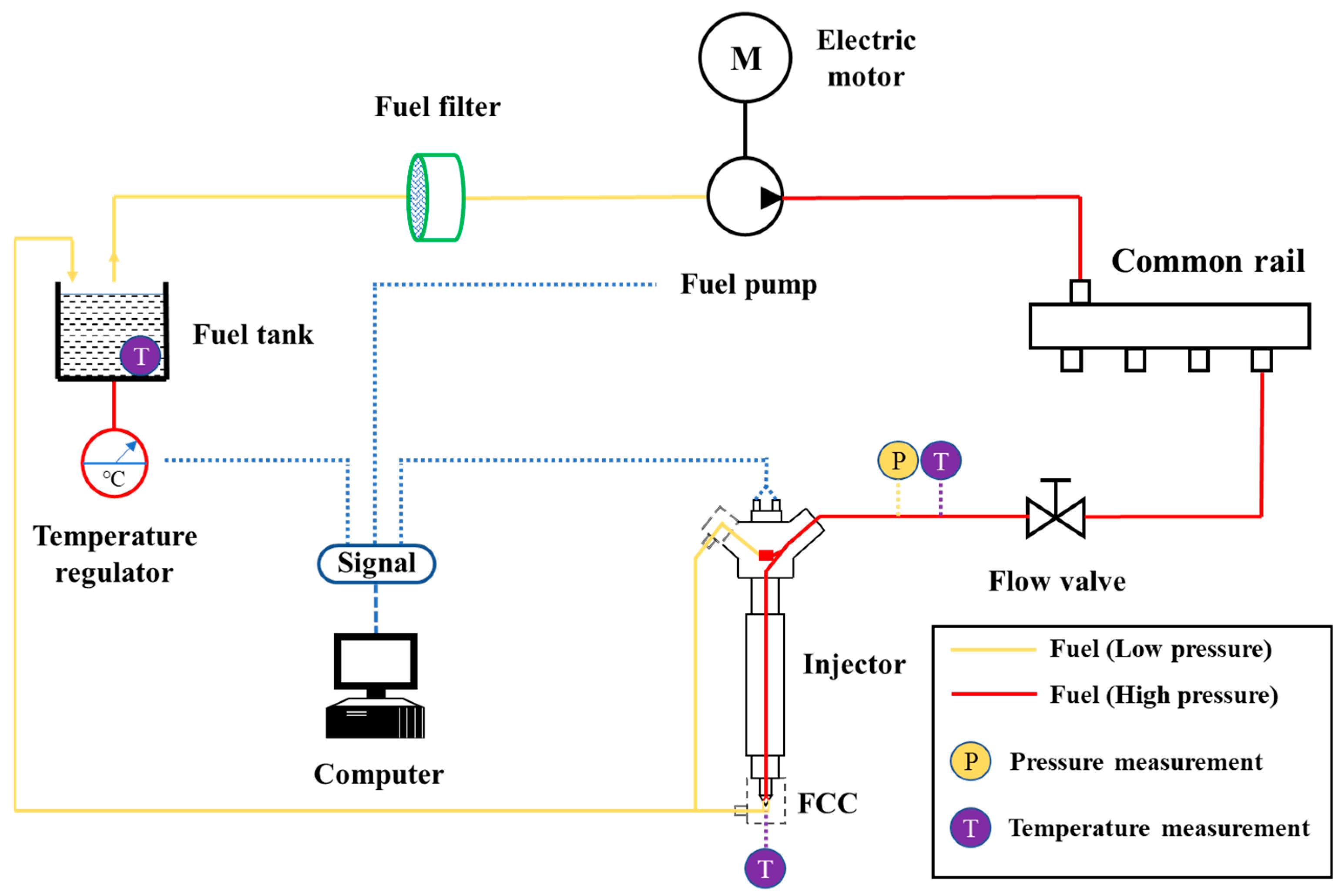
2. Description of the Experimental System

In this study, a Bosch CRIN 2 high-pressure CR injector was used to conduct experiments on the fuel temperature increase at the nozzle. To measure the fuel temperature after the nozzle holes, we processed a matching fuel collecting chamber (FCC) according to the structure of the nozzle, such that the nozzle head could be inserted into the FCC, which was convenient for measuring the fuel temperature. The junction between the nozzle head and the top orifice of the FCC was sealed to prevent fuel leakage. The FCC was a metal cylinder with a central through hole of 7 mm. The sidewall and bottom of the FCC were provided with corresponding orifices for inserting the return tubing and temperature sensor, respectively. The diameter of the fuel return hole on the side was 8 mm, which was vertically connected to the central through hole. The return tubing and temperature sensor were connected to the FCC by using a screw and sealed with sealant. In the experiment, a thermal resistance temperature sensor PT100 was used to measure the fuel temperature in the FCC; the temperature sensor had a measurement range of −50–200 °C and a maximum error of ±1 °C. To avoid the possible influence of high-momentum fuel injected from the nozzle holes on the measurement of the PT100, the PT100 was limited to 20 mm behind the nozzle holes. To measure the injector inlet temperature, a Kistler 4067 temperature sensor was installed at the injector, which was used to measure the fuel temperature (temperature range of 20–120 °C). Detailed parameters of the test device are described in [20]. A schematic of the experimental setup is shown in Figure 1.
In the experimental conditions, the initial fuel temperature T0 was 25 °C, the injection pressure P of the CR injector was controlled within a range of 0–120 MPa, and the pulse width t and injection frequency ƒ had constant values of 1.2 ms and 100 Hz, respectively. This study used ISO 4113 fuel oil, which is an international-standard experimental fuel. In the experiments, the speed of the high-pressure fuel pump was adjusted using a computer control panel on the test bench. The control panel also set the fuel temperature in the tank with an accuracy of 2 °C. The high-pressure fuel pump compressed the fuel and transported it into the CR pipe. The fuel was then transported into the injector to complete the fuel supply through the high-pressure fuel pipe. After the computer output the drive signal, the injector started to operate. To measure the fuel heating at the nozzle during the experiment, the temperature increase ΔT was used in this study, where ΔT is defined as the fuel temperature in the FCC minus the initial fuel temperature at the injector inlet. The fuel tank temperature was adjusted to ensure that the fuel temperature at the injector inlet was within a range of 25 ± 2 °C under various experimental conditions to minimize the influence of the initial fuel temperature on the fuel heating. Although the injector used in this study could reach a maximum injection pressure of 160 MPa, the fuel temperature increased with an increase in injection pressure. Owing to the limitation of temperature adjustment power, when the injection pressure was greater than 120 MPa, rapid reduction in the fuel temperature in the fuel tank could not be achieved to ensure that the fuel temperature at the inlet of the injector is maintained within a range of 25 ± 2 °C. Therefore, to ensure the rigor of the experiment and obtain a greater temperature increase to improve the measurement accuracy, the maximum experimental injection pressure in this study was 120 MPa. Because of the temperature increase at the nozzle during the injection process, a cooling channel was processed in the sidewall of the FCC at the nozzle, and water was circulated to cool the nozzle to achieve a constant fuel temperature at the nozzle during the experiment. In addition, an IFR600 single-shot measuring instrument produced by EFS was used to measure the fuel injection rate. The maximum fuel injection volume that could be measured each time was 600 mm3, and the measurement accuracy was 0.6 mm3. The instrument could measure a multi-cycle volumetric injection flow, which provided experimental data for the subsequent model calibration. The main structural parameters of the CR injector are listed in Table 1.

3. Analysis and Discussion

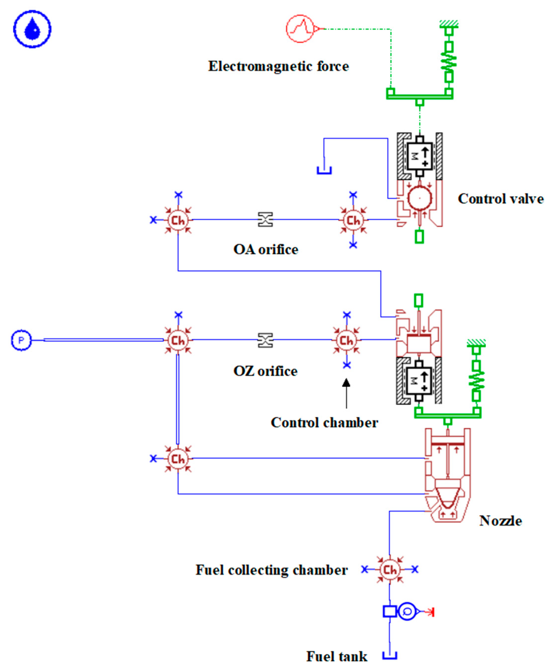
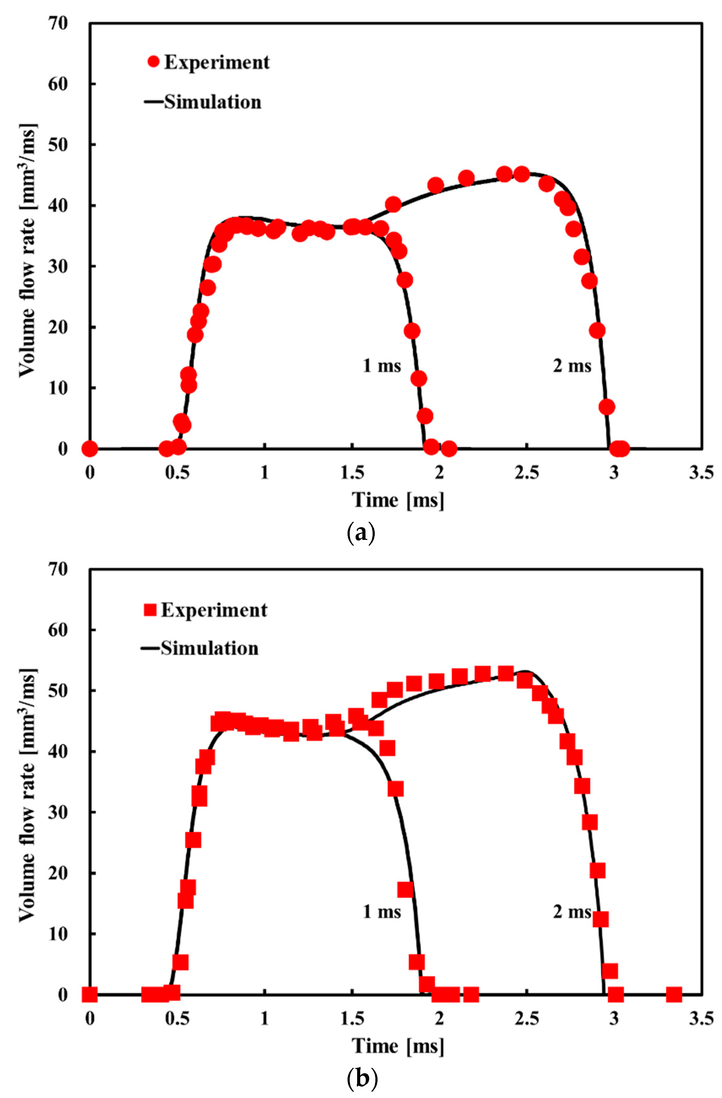
3.1. Development and Verification of the CR Injector Model under Isothermal Flow

Figure 2 shows the calculation model for the CR injector under isothermal compressible flow established in AMESim according to the structural parameters listed in Table 1. In the model, the mass of moving parts in the same motion system was regarded as a unified mass module with a concentrated mass. The fuel temperature was constant throughout the process from the inlet of the fuel injector until it was injected from the nozzle holes. The high-speed solenoid valve of the CR injector was considered for a mass-spring module to simulate its kinematic characteristics, in which the module was directly acted upon by the hydraulic driving force and electromagnetic force.
The mechanical friction and fuel leakage between moving parts could be neglected. In this study, lumped parameter sub-models were used to describe general short pipes and internal fuel tubes. For fuel tubes with significant differences in pressure, friction and inertia in different parts of the tube, distributed parameter sub-models were adopted, which fully considered the propagation, reflection and superposition of the pressure fluctuations in the pipeline to better reproduce the pressure fluctuations inside the pipeline.
Figure 3 shows a comparison of the calculated and measured volume flow rates at 1 ms and 2 ms under rail pressures of 60 and 80 MPa. It can be seen that the calculated results are in good agreement with the experimental values. The correlation coefficients, r, between the calculated results and experimental data are 0.989 and 0.985, respectively. This is not only reflected in the opening and closing moments of the fuel injection, but the results also show good consistency during the change in the fuel injection rate. The excellent agreement between the calculated results and experimental data verifies that the isothermal flow model of the CR injector established in this study is accurate, and the calculated results can be trusted.

3.2. Study on the Simulation Model of CR Injector under Adiabatic Flow

With a continuous increase in the injection pressure, the phenomenon of heat caused by pressure differences at the orifices, such as injection holes, becomes more apparent. The injection time of the CR injector is very short and scholars have suggested that this extremely short injection time leads to fuel heating caused by the pressure difference that occurs too late to be alleviated by heat transfer through the wall to the environment. The flow state of the fuel inside the injector is considered an adiabatic compressible flow under this assumption and related research has been carried out [9]. In this study, an adiabatic flow calculation model was developed based on the isothermal flow calculation model for the CR injector (Figure 2), as shown in Figure 4. In the adiabatic flow model, there were significant temperature increases in the control valve and nozzle parts owing to the inlet orifice OZ/outlet orifice OA and injection throttle holes in these two parts. Therefore, the control valve, OZ/OA orifices, control chamber, fuel sump and nozzle were selected from a thermal–hydraulic component design library. Because the constructed model was an adiabatic flow model, the above components with thermal properties did not undergo any form of heat transfer with the external environment. The heat generated when the high-pressure fuel flowed through the orifices or nozzle holes was used to heat the fuel.
Because the adiabatic flow model of the CR injector must consider the non-isothermal compressibility of the fuel, the changes in the fuel density ρ and specific heat capacity Cp were used to describe the non-isothermal compressibility of the fuel, where ρ and Cp of fuel ISO 4113 can be calculated as follows [21]:
ρ ( P , T ) = a 1 + a 2 P + a 3 P 2 + a 4 T + a 5 T 2 1 + a 6 P + a 7 P 2 + a 8 T
C p ( P , T ) = c 1 + c 2 P + c 3 P 2 + c 4 P 4 + c 5 T + c 6 T 2 1 + c 7 P + c 8 P 2 + c 9 T + c 10 T 2
where a1a8 and c1c10 are coefficients that are determined using a simulated annealing algorithm based on actual experimental data; the specific values are shown in Equations (3) and (4). It can be seen from Figure 5 and Figure 6 that the calculations match the experimental data well over the wide pressure and temperature ranges of 0–200 MPa and 30–150 °C, respectively. The correlation coefficients r between the calculated results and experimental data are 0.999 and 0.998, respectively.
{ a 1 = 834.1684 , a 2 = 3.1210 a 3 = 0.0066 , a 4 = 1.8461 a 5 = 0.0009 , a 6 = 0.0030 a 7 = 7.3434 × 10 6 , a 8 = 0.0014
{ c 1 = 1.8507 , c 2 = 0.0017 c 3 = 7.0374 × 10 6 , c 4 = 6.0455 × 10 9 c 5 = 0.0031 , c 6 = 5.6766 × 10 5 c 7 = 0.0006 , c 8 = 1.8670 × 10 6 c 9 = 0.0020 , c 10 = 1.3112 × 10 5
The calculation of fuel temperature rise is shown in Equation (5). Combined with the fuel temperature at the inlet of the injector, the current fuel temperature in the nozzle hole can be obtained. The ΔT is computed as follows:
Δ T = T d o w n s t r e a m T u p s t r e a m = ( 1 α T u p s t r e a m ) | Δ P | / ( ρ C p )
where the subscript upstream and downstream represent the upstream and downstream of the nozzle hole, respectively, the fitting formula in this paper is used to calculate the fuel density ρ and the specific heat capacity Cp in the above formula and α is the volumetric expansion coefficient of the fuel. Figure 7 shows a comparison between the fuel ΔT calculated using the adiabatic flow model and the experimental data. The variations in ΔT with the injector working time are similar. It can be seen that the main difference between the two variation trends of ΔT appeared in the rising stage of the temperature increase. The ΔT calculated by the adiabatic flow model reached a maximum rapidly in the 18 s of the injector working time and then remained unchanged. The ΔT of the experiment increased slowly and reached a maximum value in 25 min. Although there were obvious differences between the calculated results and experimental data in the variation in ΔT with the injector working time, the steady-state ΔT values were similar. The steady-state ΔT value calculated using the adiabatic flow model was 55 °C, whereas the experimental value was 55.8 °C, representing an error of 1.4%. The discrepancy between the calculated and experimental values may be because, although each injection time was short, heat transfer from the metal wall to the outside still occurred in the actual working process of the CR injector. This caused the actual ΔT at the nozzle to increase gradually rather than reach the maximum value immediately.

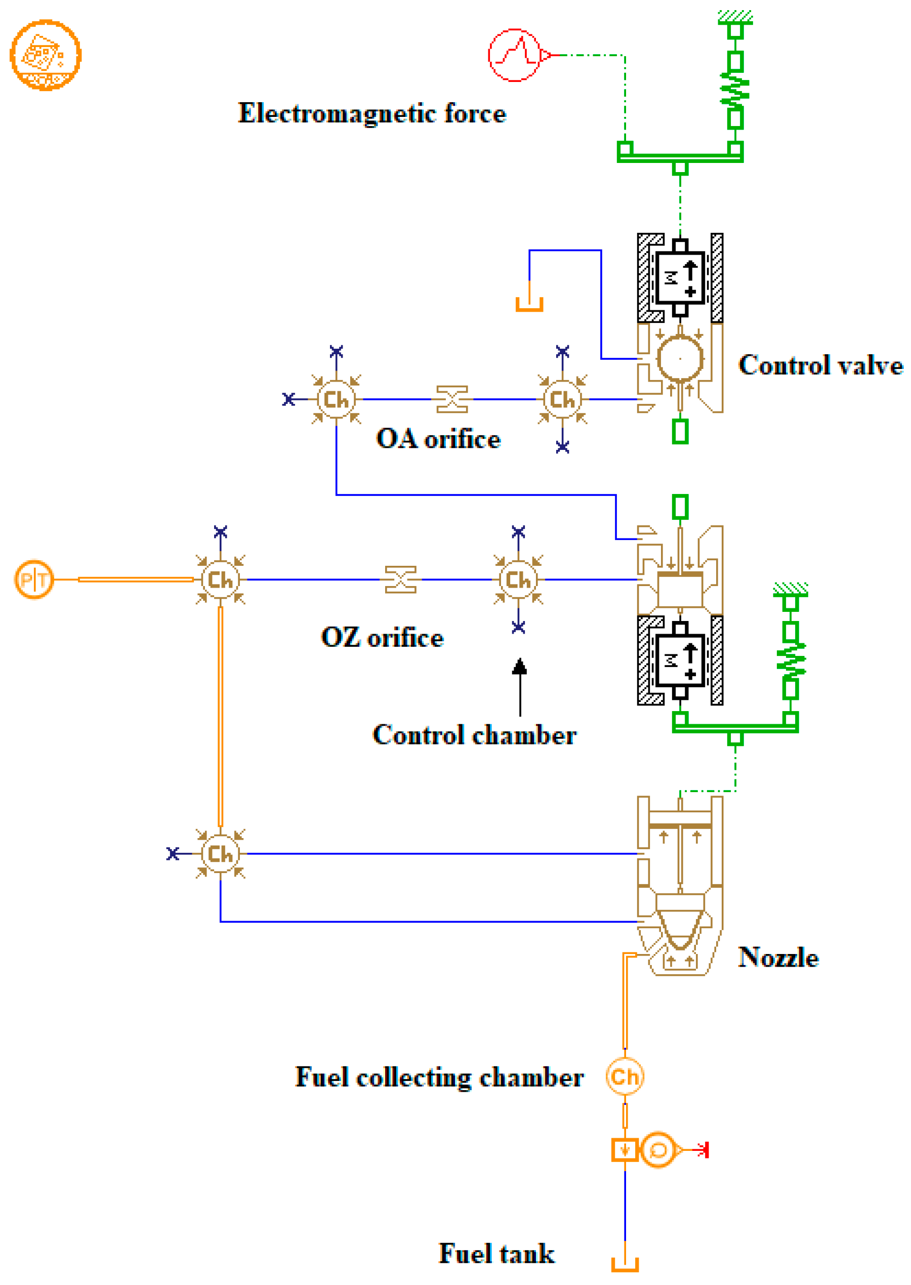
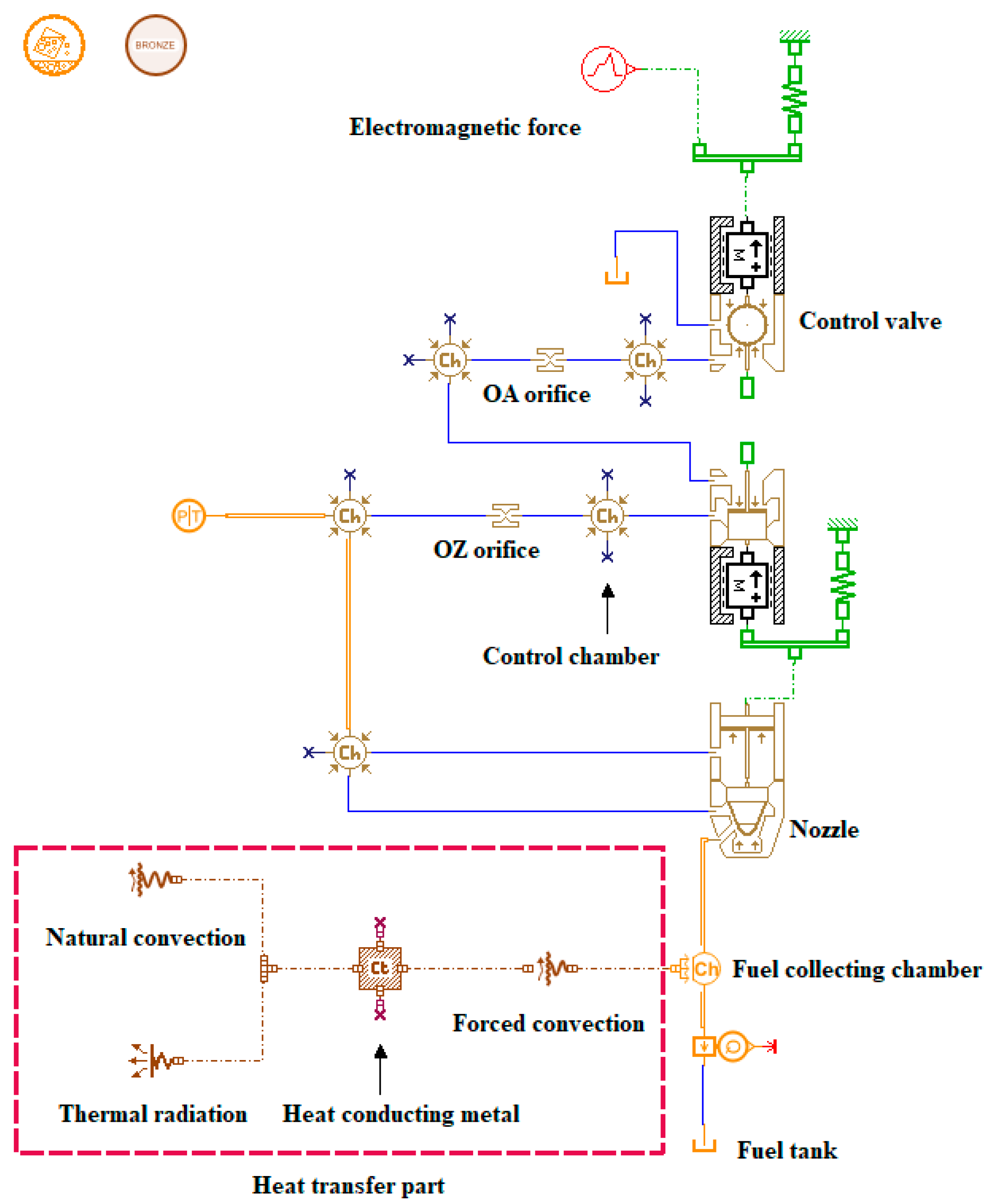
3.3. Study on the Simulation Model of CR Injector under Non-Isothermal Flow Coupled with Heat Transfer

The above analysis of the calculation results and experimental data indicates that non-isothermal properties need to be considered, such as the heat transfer between the fuel and the wall at the nozzle, and the heat transfer to the external environment during the actual injection process of the CR injector. Figure 8 shows several forms of heat transfer at the nozzle of a CR injector, which are specifically manifested as heat convection between the high-temperature fuel and the inner wall, heat conduction between the inner and outer walls and heat convection and radiation between the outer wall and the external environment. Each heat transfer process is described in detail below.
During the injection process of the CR injector, the fuel in the nozzle holes is heated owing to the Joule–Thomson effect, and the fuel temperature increases rapidly. At this time, a heat potential difference is generated between the fuel and the inner wall, and these two parts undergo forced convective heat transfer. Part of the heat from the fuel is transferred to the inner wall, which can be described using the following Equation:
Q f i w = h 1 A i w ( T f T i w )
where h1 is the heat transfer coefficient of forced convection, Aiw is the heat transfer area of the inner wall of the nozzle in contact with the high-temperature fuel, Tf is the temperature of the high-temperature fuel and Tiw is the temperature in the inner wall of the injector. In terms of the heat conduction in the wall, there is a heat potential difference between the inner and the outer walls at the nozzle. The heat conduction process of a cylindrical wall with an internal heat source is internal heat conduction. Therefore, the temperature Tow of the outer wall can be calculated using Equation (7):
T o w = T o w 0 Q f i w 4 λ 1 ( r o w r i w )
where λ1 is the thermal conductivity in the wall, row is the radius of the outer wall and riw is the radius of the inner wall. In terms of heat convection between the outer wall and the external environment at the nozzle, natural convective heat transfer will occur between the high-temperature outer wall and the external environment because the ambient temperature is constant at room temperature. The following equation is used to calculate the natural convective heat transfer:
Q o w e n v = h 2 A o w ( T o w T e n v )
where h2 is the coefficient of natural convective heat transfer, Aow is the heat transfer area of the outer wall of the nozzle in contact with the external environment and Tenv is the ambient temperature. At the same time, radiative heat transfer also occurs between the outer wall of the nozzle and the external environment. The radiative heat transfer can be calculated using the following equation:
Q r a d = σ ε A o w ( T o w 4 T e n v 4 )
where σ is the Stefan–Boltzmann constant and ε is the radiation coefficient.
Figure 9 shows the simulation model for the CR injector under non-isothermal flow coupled with heat transfer. The main difference between this model and the adiabatic flow model shown in Figure 4 is that the heat transfer is explicitly considered. The heat transfer is connected to the heat exchange interface of the FCC behind the nozzle. As shown by the dotted line in the figure, in this heat transfer module, the heat transfer processes of convection, conduction and radiation at the nozzle of the injector were fully considered. The whole transfer part was explicitly expressed as follows: the process of forced convection between the fuel and the inner wall was represented by the forced convection module connected to the FCC and the heat-conducting metal block; the heat conduction process of the wall was represented by calculation of the internal thermal energy of the heat-conducting metal block; and the natural convection and thermal radiation between the outer wall and external environment were represented by the heat-conducting metal block connected to the natural convection module and heat radiation module simultaneously. In the overall temperature increase model for the CR injector under non-isothermal flow, the non-isothermal nature and compressibility of the fuel were also considered. The density ρ and specific heat capacity Cp of the fuel were calculated using Equations (1) and (2), respectively.
It can be seen from Figure 10 that the ΔT calculated by the non-isothermal flow model coupled with heat transfer has a better coincidence with the experimental data than the model data in Figure 7. The correlation coefficient r between the calculated results and experimental data is 0.989. Particularly in the temperature increase phase, the calculated ΔT gradually increases with the injection working time, rather than rapidly increasing to the maximum value. In addition, Figure 10 also shows that the final steady-state ΔT calculated by the coupled heat transfer model is 0.8 °C lower than that calculated by the adiabatic flow model. Although the consideration of heat transfer characteristics makes the non-isothermal model of the CR injector more consistent with the experimental data in terms of temperature increase prediction, there is still a specific deviation from the experimental data. This is because the heat transfer area in the heat transfer model was calculated through the equivalent calculation of the structural parameters, which had a certain error with the actual heat transfer area. In addition, the heat transfer coefficient of the heat exchange module should be calculated using a function that changes with temperature; however, currently, this model is currently based on a fixed value.

3.4. Influence of Fuel Heating Effects on the Cycle Injection Quantity

After obtaining the fuel temperature in the nozzle hole, combined with the fuel pressure in the nozzle hole, the fuel density under the current temperature and pressure can be calculated according to the fuel density physical property formula. Then, the volume flow rate of fuel injected from the nozzle holes can be calculated by Equation (10):
d V d t = C d A 2 | Δ P | ρ
where Cd is the flow coefficient and A is the geometric flow area. In fact, the mass flow rate of fuel is the parameter that determines the amount of cycle injection quantity. The mass flow rate is calculated according to Equation (11) and the cycle injection quantity m can be calculated by integrating the fuel injection time from Equation (11).
d m d t = ρ d V d t
Figure 11 shows the variation in the cycle injection quantity calculated using the CR injector model with the injector working time under different conditions. For convenience of description and analysis, the calculation model for the CR injector under isothermal flow is briefly described as the isothermal model. Similarly, the calculation model for the CR injector under adiabatic flow is briefly described as the adiabatic model. The calculation model of the CR injector with non-isothermal flow coupled with heat transfer is briefly described as the heat transfer model.
As shown in Figure 11, the initial fuel temperatures in the isothermal, adiabatic and heat transfer models were the same. Therefore, the cycle injection quantity calculated using the three models was all 83.15 mg at the beginning stage. However, with an increase in the fuel injector working time, differences in the cycle injection quantities calculated by the different models with time gradually became distinct. The cycle injection quantity calculated by the isothermal model did not change and remained at 83.15 mg at all times because the fuel in the injection holes was always in a constant temperature state and, thus, the thermophysical properties of the fuel did not change. Compared with the isothermal model, the cycle injection quantity calculated by the adiabatic model decreased rapidly from 83.15 mg to 78.95 mg, and then stabilized at this value as the injector working time increased. This behavior was due to the rapid increase in fuel temperature under adiabatic flow, which then stabilized. The fuel density decreased with increasing temperature, resulting in a decrease in the cycle injection quantity. It can be seen from the cycle injection quantity curve calculated using the heat transfer model that the cycle injection quantity decreased significantly by 3.44 mg within the first 0–10 min of the injector working time. During minutes 10–20 of the injector working time, ΔT increased slowly. The corresponding decrease rate of the cycle injection quantity also slowed, and the cycle injection quantity only decreased by 0.23 mg in this period. After the injector worked for more than 25 min, the cycle injection quantity stabilized at 79.48 mg because the ΔT of the fuel at the nozzle stabilized after 10 min. Another phenomenon seen in Figure 11 is that the cycle fuel injection calculated by the heat transfer model is 0.53 mg higher than that calculated by the adiabatic model. This is because the maximum fuel temperature value calculated by the heat transfer model was lower, leading to a higher fuel density at the nozzle and a corresponding larger cycle injection quantity.

3.5. Influence of Injection Pressure on Cycle Injection Quantity under Thermal Effect

ΔP is an essential factor that affects the fuel temperature increase at the nozzle of the CR injector. Therefore, it is necessary to analyze the influence of the fuel heating on the cycle injection quantity during the injection process under different ΔP values. As shown in Figure 12, the cycle injection quantities under different ΔP gradually decreased with the injector working time. For example, under the condition of ΔP = 140 MPa, the cycle injection quantity gradually decreased from 90.68 mg to 87.15 mg after the injector worked for 10 min, representing a decrease of 3.53 mg (3.9%); it then remained stable in the following working time. In addition, the influence of the fuel heating effect on the cycle injection quantity differed under different injection pressures. With an increase in the injection pressure, the cycle injection quantity decreased to a greater extent. Under the condition of ΔP = 200 MPa, the cycle injection quantity decreased by 6.48 mg (5.8%). However, the cycle injection quantities under ΔP = 250 MPa and 300 MPa decreased further, by 6.7% and 7.8%, respectively. At the same time, it can be observed that the cycle injection quantity reached a steady value after the injector worked for 20 min when ΔP= 140 MPa; however, the time required to reach a steady value decreased when ΔP was higher. When ΔP was 300 MPa, the cycle injection quantity reached a steady value just after the injector worked for just 5 min. This occurs because the higher the ΔP, the greater the fuel heating will be, thus, leading to a faster temperature increase and greater maximum ΔT. Therefore, the greater the speed and degree of the fuel density reduction at the nozzle, the more the cycle injection quantity will decrease.
Under the condition of high-pressure/ultra-high-pressure injection, the heat generated by a high ΔP directly changes the physical properties of the fuel, which has an important influence on the cycle injection quantity. Therefore, to achieve more accurate control of the cycle injection quantity, modification of the cycle injection quantity fluctuation under thermal effect should be included in the control strategy of the CR system.

4. Conclusions

This study investigated the dynamic injection prediction model for a high-pressure CR injector, and the conclusions are as follows:
(1)
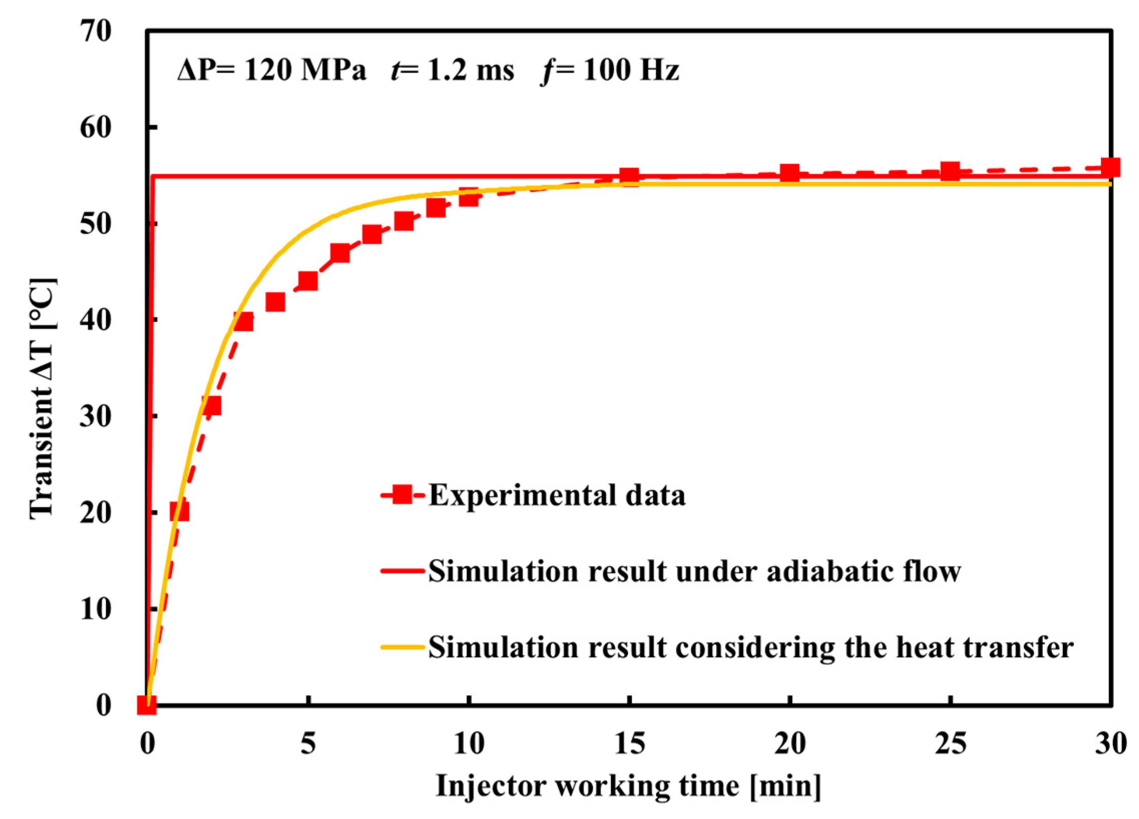
The transient ΔT at the nozzle calculated by the adiabatic flow model of the CR injector increases rapidly to the maximum value in a very short time, which differs from the behavior of the experimental ΔT with the fuel injector working time. Therefore, the adiabatic flow model cannot reflect the non-isothermal phenomena that occur during the actual injection process of the injector. The ΔT calculated by the model under non-isothermal flow coupled with heat transfer is in good agreement with the experimental data overall, and it can accurately describe the transient ΔT at the nozzle.
(2)
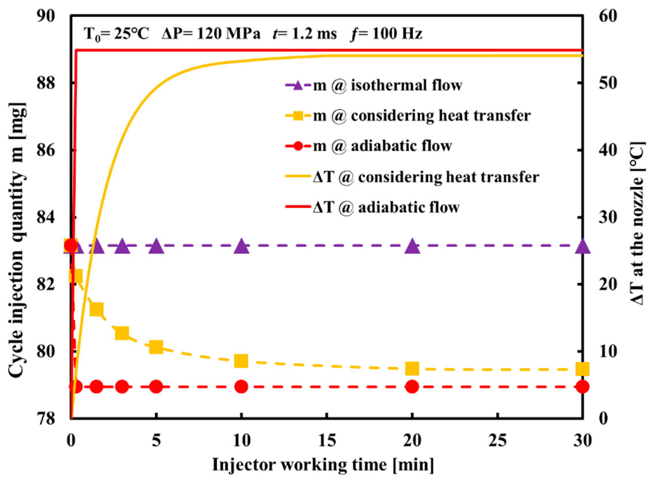
Under the assumption that the fuel in the CR injector is isothermal, the model cannot calculate the cycle injection quantity under the thermal effect in the actual working process. The cycle injection quantity calculated by the adiabatic flow model decreases rapidly owing to the rapid increase in temperature at the beginning of the injector working time, after which it remains unchanged. The cycle injection quantity calculated by the non-isothermal flow model coupled with heat transfer gradually decreases with the injector working time until it stabilizes. The difference in the cycle injection quantity calculated by the two models with the change in injector working time is mainly caused by different thermal phenomena at the nozzle.
(3)
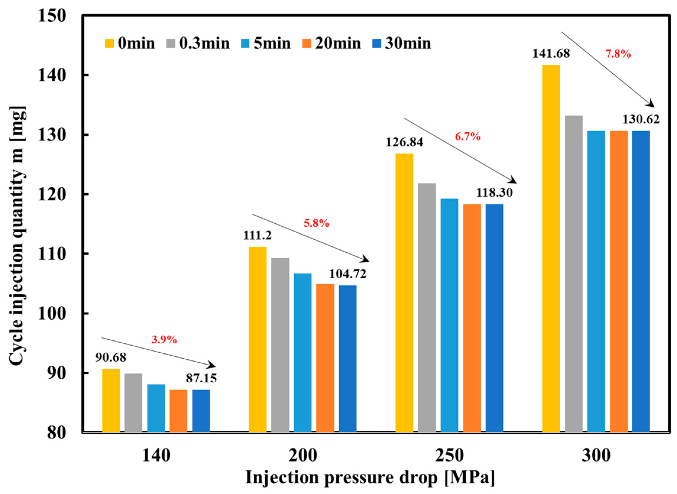
As the injection pressure increases, the greater ΔP causes the fuel in the nozzle holes to generate more heat, resulting in a greater reduction in the cycle injection quantity under the action of heat. Therefore, for a high-pressure CR system with high-pressure and ultra-high-pressure injections, it is necessary to consider the influence of heat generation caused by ΔP on the cycle injection quantity when performing precise control of the cycle injection quantity. This conclusion has a guiding role for the control system, achieving precise and flexible control of the injection characteristics.
(4)
The experimental data and simulation results in this study demonstrate that the thermal effect at the nozzle of a high-pressure CR injector cannot be ignored, as the heat transfer directly affects the physical properties of the fuel and then reduces the cycle injection quantity. With stricter emission regulations, higher injection pressure requirements will make the thermal effect at the nozzle more obvious, which may significantly affect the injection characteristics. The research methods and results of this paper are informative and instructive. In further research, it is necessary to transform the test bench to realize the experimental measurement of the cycle injection quantity at different injection times under the working state of the injector. The experimental measurement will be mainly carried out in order to compare with the calculation results and prove the significance of this research from an experimental point of view.

Author Contributions

Conceptualization, Z.L. (Zhenming Liu), Z.L. (Ziming Li) and J.W.; Methodology, Z.L. (Zhenming Liu), Z.L. (Ziming Li) and J.L.; Software, J.L.; Validation, Z.L. (Zhenming Liu) and Z.L. (Ziming Li); Formal analysis, J.L.; Resources, P.C.; Writing—original draft preparation, Z.L.(Zhenming Liu) and Z.L.(Ziming Li); Writing—review and editing, Z.L. (Zhenming Liu), Z.L. (Ziming Li), J.W. and P.C.; Supervision, Z.L. (Zhenming Liu); Funding acquisition, Z.L. (Zhenming Liu). All authors have read and agreed to the published version of the manuscript.

Funding

This research was funded by the National Natural Science Foundation of China, grant No. 51879269.

Institutional Review Board Statement

Not applicable.

Informed Consent Statement

Not applicable.

Data Availability Statement

Some data, models, or code that support the findings of this study are available from the corresponding author upon reasonable request.

Conflicts of Interest

The authors declare no conflict of interest.

References

  1. Park, S.H.; Yoon, S.H.; Lee, C.S. Effects of multiple-injection strategies on overall spray behavior, combustion, and emissions reduction characteristics of biodiesel fuel. Appl. Energy 2011, 88, 88–98. [Google Scholar] [CrossRef]
  2. Wang, G.; Yu, W.; Li, X.; Su, Y.; Yang, R.; Wu, W. Experimental and numerical study on the influence of intake swirl on fuel spray and in-cylinder combustion characteristics on large bore diesel engine. Fuel 2019, 237, 209–221. [Google Scholar] [CrossRef]
  3. Gumus, M.; Sayin, C.; Canakci, M. The impact of fuel injection pressure on the exhaust emissions of a direct injection diesel engine fueled with biodiesel–diesel fuel blends. Fuel 2012, 95, 486–494. [Google Scholar] [CrossRef]
  4. Theodorakakos, A.; Strotos, G.; Mitroglou, N.; Atkin, C.; Gavaises, M. Friction-induced heating in nozzle hole micro-channels under extreme fuel pressurisation. Fuel 2014, 123, 143–150. [Google Scholar] [CrossRef]
  5. Strotos, G.; Koukouvinis, P.; Theodorakakos, A.; Gavaises, M.; Bergeles, G. Transient heating effects in high pressure Diesel injector nozzles. Int. J. Heat Fluid Flow 2015, 51, 257–267. [Google Scholar] [CrossRef] [Green Version]
  6. Zhao, J.; Wei, K.; Yue, P. Investigation of maximum temperature rise on high pressure common rail injector nozzle. SAE Technical Paper 2009, 2019-01-0276. [Google Scholar] [CrossRef]
  7. Zhang, X.; He, Z.; Wang, Q.; Tao, X.; Zhou, Z.; Xia, X.; Zhang, W. Effect of fuel temperature on cavitation flow inside vertical multi-hole nozzles and spray characteristics with different nozzle geometries. Exp. Therm. Fluid Sci. 2018, 91, 374–387. [Google Scholar] [CrossRef]
  8. Theodorakakos, A.; Mitroglou, N.; Gavaises, M. Simulation of heating effects in cavitating flows through Diesel fuel injectors caused by extreme fuel pressurisation. In Proceedings of the 8th International Symposium on Cavitation, Singapore, 14–16 August 2012. [Google Scholar]
  9. Salvador, F.J.; Gimeno, J.; Martín, J.; Carreres, M. Thermal effects on the diesel injector performance through adiabatic 1D modelling. Part I: Model description and assessment of the adiabatic flow hypothesis. Fuel 2020, 260, 116348. [Google Scholar] [CrossRef]
  10. Payri, R.; Salvador, F.J.; Carreres, M.; Belmar-Gil, M. Thermal effects on the diesel injector performance through adiabatic 1D modelling. Part II: Model validation, results of the simulations and discussion. Fuel 2020, 260, 115663. [Google Scholar] [CrossRef]
  11. Wang, Z.; Ding, H.; Wyszynski, M.L.; Tian, J.; Xu, H. Experimental study on diesel fuel injection characteristics under cold start conditions with single and split injection strategies. Fuel Processing Technol. 2015, 131, 213–222. [Google Scholar] [CrossRef]
  12. Salvador, F.J.; Gimeno, J.; Carreres, M.; Crialesi-Esposito, M. Experimental assessment of the fuel heating and the validity of the assumption of adiabatic flow through the internal orifices of a diesel injector. Fuel 2017, 188, 442–451. [Google Scholar] [CrossRef] [Green Version]
  13. Catania, A.E.; Ferrari, A.; Spessa, E. Temperature variations in the simulation of high-pressure injection-system transient flows under cavitation. Int. J. Heat Mass Transf. 2008, 51, 2090–2107. [Google Scholar] [CrossRef]
  14. Shi, J.M.; Arafin, M.S. CFD investigation of fuel property effect on cavitating flow in generic nozzle geometries. In Proceedings of the ILASS-Europe 2010, 23rd Annual Conference on Liquid Atomization and Spray Systems, Brno, Czech Republic, 6–8 September 2010. [Google Scholar]
  15. Giorgi, G.; Ficarella, A.; Tarantino, M. Evaluating cavitation regimes in an internal orifice at different temperatures using frequency analysis and visualization. Int. J. Heat Fluid Flow 2013, 39, 160–172. [Google Scholar] [CrossRef]
  16. Cao, T.; He, Z.; Si, Z.; L-Seesy, A.I.E.; Guan, W.; Zhou, H.; Wang, Q. Optical experimental study on cavitation development with different patterns in diesel injector nozzles at different fuel temperatures. Exp. Fluids 2020, 61, 185. [Google Scholar] [CrossRef]
  17. Boudy, F.; Seers, P. Impact of physical properties of biodiesel on the injection process in a common-rail direct injection system. Energy Convers. Manag. 2009, 50, 2905–2912. [Google Scholar] [CrossRef]
  18. Han, D.; Li, K.; Duan, Y.; Lin, H.; Huang, Z. Numerical study on fuel physical effects on the split injection processes on a common rail injection system. Energy Convers. Manag. 2017, 134, 47–58. [Google Scholar] [CrossRef]
  19. Boehman, A.L.; Morris, D.; Szybist, J. The Impact of the Bulk Modulus of Diesel Fuels on Fuel Injection Timing. Energy Fuels 2004, 18, 1877–1882. [Google Scholar] [CrossRef]
  20. Zhao, J.; Lu, X.; Grekhov, L. Experimental study on the fuel heating at the nozzle of the high pressure common-rail injector. Fuel 2021, 283, 119281. [Google Scholar] [CrossRef]
  21. Yue, P.; Zhao, J.; Wei, K.; Ma, X. The fluid–structure–thermal coupled characteristics of the leakage rate of piston couples interface for common-rail injector. Proc. Inst. Mech. Eng. Part C J. Mech. Eng. Sci. 2019, 233, 5826–5835. [Google Scholar] [CrossRef]
  22. Ndiaye, E.H.I.; Bazile, J.-P.; Nasri, D.; Boned, C.; Daridon, J.L. High pressure thermophysical characterization of fuel used for testing and calibrating diesel injection systems. Fuel 2012, 98, 288–294. [Google Scholar] [CrossRef]
  23. Chorążewski, M.; Dergal, F.; Sawaya, T.; Mokbel, I.; Grolier, J.-P.E.; Jose, J. Thermophysical properties of Normafluid (ISO 4113) over wide pressure and temperature ranges. Fuel 2013, 105, 440–450. [Google Scholar] [CrossRef]
Figure 1. Experimental system for measuring the temperature increase in a CR injector.
Energies 15 05067 g001
Figure 2. The simulation model of CR injector under isothermal flow.
Energies 15 05067 g002
Figure 3. Comparison of the calculation results of isothermal flow model and experimental data under different rail pressures: (a) 60 MPa; (b) 80 MPa.
Energies 15 05067 g003
Figure 4. The simulation model of CR injector under adiabatic flow.
Energies 15 05067 g004
Figure 5. ρ calculated with Equation (1) compared with experimental data from [22].
Energies 15 05067 g005
Figure 6. Cp calculated with Equation (2) compared with experimental data from [23].
Energies 15 05067 g006
Figure 7. Comparison of the calculated ΔT under adiabatic flow with experimental data.
Energies 15 05067 g007
Figure 8. Diagram of the fuel heat transfer process at the nozzle of the CR injector.
Energies 15 05067 g008
Figure 9. The simulation model of the CR injector under non-isothermal flow coupled with heat transfer process.
Energies 15 05067 g009
Figure 10. Comparison of the ΔT calculation results under non-isothermal flow coupled with heat transfer process and adiabatic flow with experimental data.
Energies 15 05067 g010
Figure 11. The calculation results of cycle injection quantity against the injector working time under different conditions.
Energies 15 05067 g011
Figure 12. Change in the cycle injection quantity calculated with consideration of the thermal effect.
Energies 15 05067 g012
Table 1. Main structural parameters of the CR injector.
Parameters (Unit)Value
Ball diameter of control valve (mm)1.33
Lift of armature (mm)0.07
Diameter of OA orifice (mm)0.34
Diameter of OZ orifice (mm)0.23
Lift of needle (mm)0.25
Diameter of needle (mm)4
Pre-tightening force of needle spring (N)50
Diameter of nozzle hole (mm)0.157
Number of nozzle holes9
Publisher’s Note: MDPI stays neutral with regard to jurisdictional claims in published maps and institutional affiliations.

