Article

Research on Wave and Energy Reduction Performance of Floating Breakwater Based on S-Shaped Runner

1
Faculty of Mechanical Engineering & Mechanics, Ningbo University, Ningbo 315211, China
2
School of Mechanical Engineering and Automation, College of Science & Technology, Ningbo University, Cixi 315300, China
*
Author to whom correspondence should be addressed.
Energies 2022, 15(14), 5148; https://doi.org/10.3390/en15145148
Submission received: 30 May 2022 / Revised: 8 July 2022 / Accepted: 14 July 2022 / Published: 15 July 2022
(This article belongs to the Special Issue Electrical Systems for Marine Renewable Energy Applications)

Abstract

:
Aiming at the breeding environment where the construction of marine pastures requires low wind and waves, a floating breakwater (FB) with a Savonius type (referred to as S type) runner with wave absorption and energy reduction function is studied for wave absorption and energy reduction in aquaculture sea areas. The wave-absorbing and energy-reducing performance of the floating breakwater is studied by the method of combining numerical simulation and experiment. Using Star-CCM+ numerical simulation software, based on linear wave theory and energy conservation law, using overlapping grid technology, calling DFBI model, second-order time discretization, a three-dimensional flow field model of the floating breakwater was established and numerically simulated. At the same time, a floating breakwater physical test system was developed for experimental verification, the transmission wave and the conversion power consumption of the S-shaped runner under different wave heights and different periods were measured, and the results Please carefully check the accuracy of names and affiliations. of numerical simulation and physical experiments were comprehensively evaluated. The research results show that the floating breakwater based on the S-shaped runner has the functions of reducing the wave height and reducing the wave energy, which have guiding significance for practical engineering.

1. Introduction

As a kind of breakwater structure, floating breakwater means that the project cost is less affected by the water depth, the foundation adaptability is strong, and construction and demolition are relatively convenient. Floating breakwaters are widely used in deep-sea aquaculture because of their economy and practicality. However, aquaculture in open seas faces the threat of greater wind and waves, and aquaculture equipment is easily damaged. Therefore, it is necessary to study a new type of floating breakwater suitable for application in open seas to reduce the energy of waves and flow fields without hindering the exchange of water bodies in aquaculture waters [1].
Shih et al. [2] studied the high-permeability dense small-diameter pipeline as the research object and discussed its influence on seawater convection and exchange, and could achieve an effective wave elimination effect. Wang et al. [3] studied the wave-absorbing effect of a new type of hanging curtain flexible floating breakwater. Syed et al. [4] studied a floating system consisting of three pontoon connections, and the results showed that the spacing between the pontoons is one of the important factors affecting the transmission and reflection coefficients of the floating breakwater system. Rahman et al. [5] concluded that the underwater buoy plays an important role in the dissipation of wave energy through the comparative analysis of numerical calculation and physical model test. Bayram et al. [6] studied the influence of wave period on the transmission coefficient of floating breakwaters. Through physical experiments, it was known that the transmission coefficient of floating breakwaters changes greatly when the wave period changes.
Yu et al. [7] studied the wave absorption performance, motion response and mooring tension response of floating breakwater under the action of linear regular waves. Yao et al. [8,9] analyzed the mechanism of flow reduction through the detailed study of velocity cloud map and vector diagram, summarized the change law of velocity field, and further studied the flow reduction effect of S-type runner under different tip speed ratios. Ji et al. [10,11,12] proposed a system of porous floating breakwaters with different distances. The research results show that the double-row floating breakwater system has better performance than the single-row floating breakwater system in many aspects. A series of experiments were conducted in the trough to measure the resulting transmission coefficients, reflection coefficients, motion responses and mooring forces to quantify the hydrodynamic performance of the breakwater. Zheng [13] used STAR CCM+ software to model the floating breakwater and simulated the transmission coefficient and motion response of the single-box floating breakwater through the overlapping grid division technology. Ge [14] conducted a two-dimensional physical model test to study the hydrodynamic characteristics of the new type of floating raft breakwater under the action of long-period waves and discussed the relative width, relative inclination width, and relative front entry of the floating embankment under the action of regular waves. The influence of the connection mode between the depth and inclination modules on the wave dissipation characteristics and the anchor chain force characteristics of the structure. Zhang et al. [15] analyzed the different distances between the straight wall and the square box and focused on the influence of the nearshore reflection on the reflection coefficient, transmission coefficient, and wave energy capture efficiency of the integrated system under the conditions of small gaps and narrow gaps and large gaps. Qu et al. [16] systematically analyzed the influence of main parameters such as wave height, water depth, submerged depth, separation distance and the aspect ratio of the breakwater on the performance of the floating breakwater. Zhang et al. [17] used Star-CCM+ software to establish a numerical model of a wave tank to study the interaction between waves and wave energy converters and completed the verification of time and space step convergence research. The effect of wavelength on the motion response and transmission coefficient of the floating box breakwater model is studied.
Based on the research on floating breakwaters by domestic and foreign scholars, most of them analyze the transmission coefficient, motion response, wave absorption mechanism, etc. of floating breakwaters for their different structures, different connection methods, etc. [18]. However, for the application of S-type runners to floating breakwaters, there are relatively few studies on wavefield analysis. Therefore, this paper studies the wave-absorbing and current-reducing performance of the floating breakwater based on the S-shaped runner. By changing the relative spacing W/λ of the floating body, changing the water entry depth of the runner, and studying its hydrodynamics under different working conditions performance. The results have a certain reference value for guiding the design of this type of breakwater.

2. General Situation of Floating Breakwater

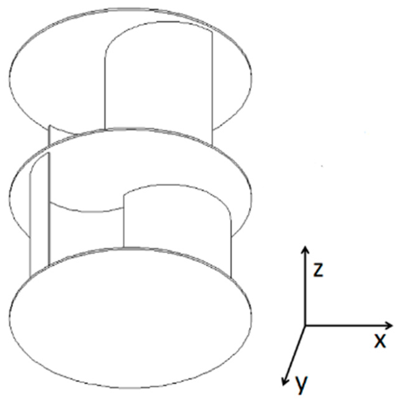
2.1. Geometric Model

The single-floating tube floating body is not very good at absorbing waves for medium and long waves. The waves often pass through transmission, and there is no frictional energy dissipation and wave absorbing in the tube. Additionally, the buoyancy of the single-floating tube float is not enough to suspend the Savonius blade; therefore, the double-floating tube structure design is adopted. For the selection of double-floating pipe material, we chose to use high-density polyethylene (HDPE). The density of HDPE material is between 0.940 and 0.976 g/cm3, which can float on water’s surface. To improve its wave-absorbing effect, scholars at home and abroad have improved its wave-absorbing performance in many aspects, including double buoy, buoy-vertical plate, and buoy-horizontal plate.
The floating breakwater based on the S-shaped runner mainly includes the S-shaped runner group and the HDPE floating pipe group. The S-type runner group is suspended under the HDPE floating pipe through the iron chain mooring at a certain density, and the S-type runner groups are also connected by a hollow shaft to form a grid array distributed energy reduction system; the HDPE floating pipe group includes It consists of two HDPE floating pipes and their connecting brackets, which are moored on the pile foundation through cable tensioning. Referring to the actual situation of the engineering background and the conditions of the experimental equipment, the geometric parameters of the floating body and the runner of the floating breakwater are shown in Table 1, and the actual physical model of the experiment is shown in Figure 1 and Figure 2.
During the rotation of the traditional first-order S-shaped runner, the runner will generate negative torque when it turns to a certain angle. Usually, another runner is added to one side of the runner to form a second-order S-shaped runner. There is a 90° angle between the impellers, and the number of blades is changed from two blades to four blades. The S-type blade has a simple structure, low operating speed, good starting performance, and can accept fluid from any direction. Because the S-type runner can receive energy in multiple directions perpendicular to the axis, according to the motion state of the water molecules in the wave, the Savonius runner is arranged in a horizontal axis, which can maximize the consumption of wave energy. Therefore, based on the traditional double-buoy-type breakwater, this paper designs a new type of wave-absorbing and energy-capturing breakwater by arranging the Savonius runner with the horizontal axis. According to the open sea wave data, engineering application background, and the size of the experimental tank and the generated waveform, the experimental model is designed with a geometric ratio of 1:5. The geometric characteristics and hydrodynamic parameters of the floating breakwater are shown in Table 1 and Table 2.

2.2. S-Type Runner Energy Conversion Model

According to the principle of energy conservation, the incident wave energy is equal to the reflected wave energy, the transmitted wave energy, the wave energy loss, and the kinetic energy driving the S-shaped runner. The power of the incident wave is finally converted into four-part power [19].
P wave = P c + P r + P t + P s  
where P c is the dissipation power, P r is the reflected wave power, P t is the transmitted wave power, and P s is the Sblade power. The incident wave power formula is
P wave = 1 8 ρ g H i 2 C g = 1 32 π ρ g 2 H i 2 T
where ρ is the density of water, g is the acceleration of gravity, H i is the height of the incident wave, C g is the group velocity, and T is the period of the incident wave
Both the reflected wave power and the transmitted wave power are related to the reflected wave height and the transmitted wave height. Calculate the power requirement of the S-shaped runner to obtain its moment of inertia and measure its angular velocity. The S-type runner group consists of three two-stage S-type runners, including the rotation of the end cover and the rotation of the runner. The intermediate shaft can be ignored due to its small moment of inertia.
The formula for calculating the moment of inertia of the S-type runner is as follows
I = J t = J i + J d = 2 × ( 1 2 0 2 π R λ R 2 d l + m i l 2 ) + 3 0 R 2 π r 3 h ρ d r = m i ( d 2 ) 2 + 2 m i ( d e 2 ) 2 + 3 m d ( D d 2 ) 2
where m i is the mass of the impeller, m d is the mass of the end disc, d is the blade diameter, e is the overlap rate, and Dd is the end disc diameter.
The formula for calculating the rotational energy of the S-type runner is:
W s = 1 2 I ω 2
The formula for calculating the power of the S-type runner is:
P s = T n 9550  
The capture efficiency of the runner is η
η = P s P wave  
The remainder is dissipated power
P c = P wave P r P t P s = 1 32 π ρ g 2 ( H i 2 H r 2 H t 2 ) T n 9550

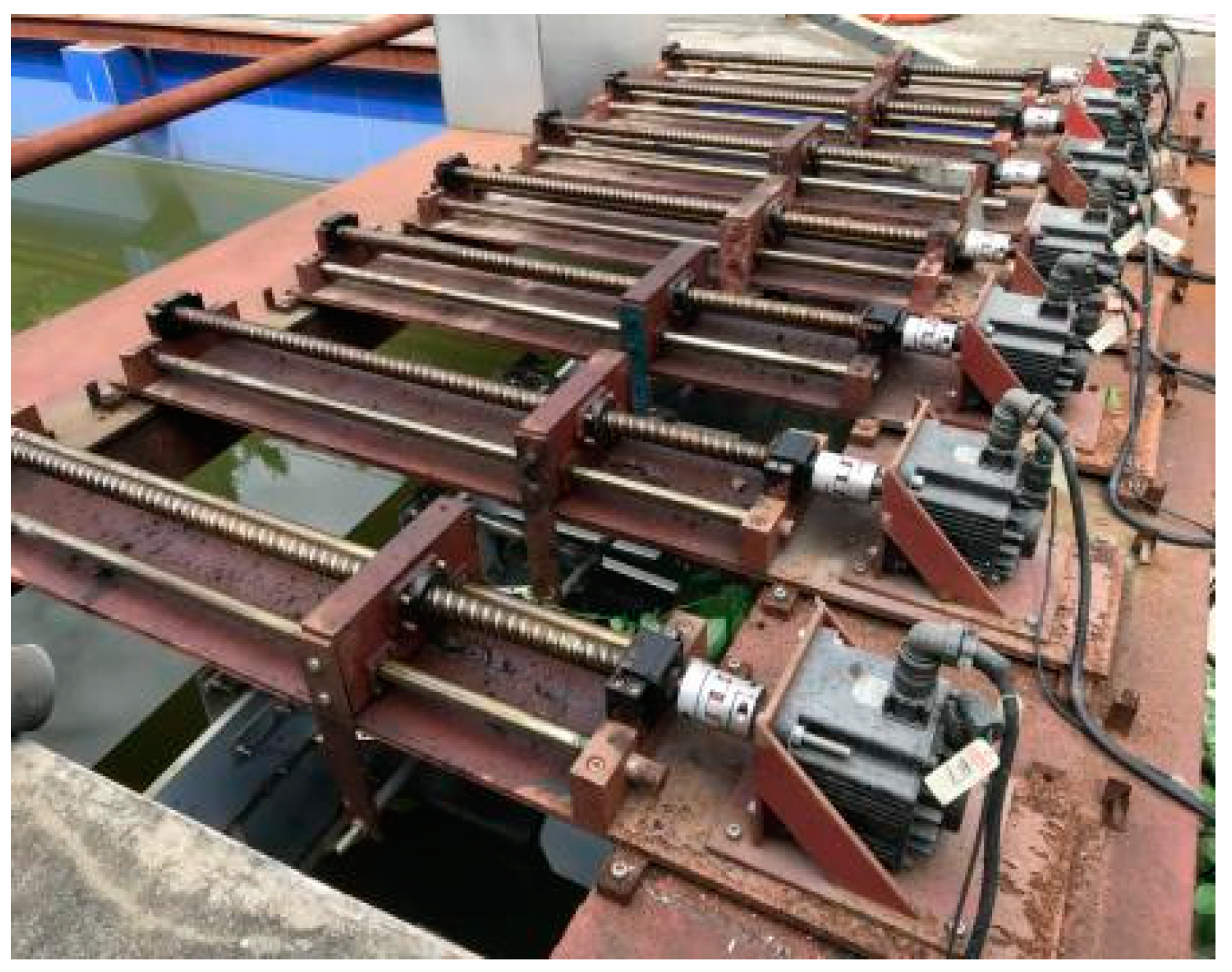
2.3. Floating Breakwater Model

The wave elimination mechanism of the floating breakwater is that the wave impact forms a reflected wave behind the breakwater, which then offsets the energy of the incident wave. In actual sea conditions, the floating breakwater is prone to periodic oscillation with the waves, and part of the energy can still be transmitted smoothly. The double-buoy breakwater is better than the single-buoy type in terms of wave absorption. The wave energy P wave undergoes a reflection and transmission when it is transmitted to the first buoy, and pushing the runner to rotate will also consume part of the wave energy P s under the water surface.
P wave = P c 1 + P r 1 + P t 1 + P s
The transmitted wave energy P t 1 is reflected and transmitted again through the second pontoon
P t 1 = P c 2 + P r 2 + P t 2
The reflected wave P r 2 will oscillate between the two buoys and gradually attenuate. The final transmitted wave energy is about P t 2 , and the wave energy loss ratio is
P c + P r 1 + P r 2 + P s P wave = H i 2 H t 2 H i 2 = 1 C t 2
The wave transmission coefficient is an important indicator of the wave-absorbing performance of the floating breakwater. The transmitted wave height is measured by a wave height meter arranged behind the embankment beyond one wavelength. The wave transmission coefficient C t is the ratio of the transmitted wave height behind the embankment to the incident wave height in front of the embankment:
C t = H t H i
where H r is the height of the reflected wave before the breakwater, H t is the height of the transmitted wave behind the breakwater, and H i is the height of the incident wave before the breakwater.

3. Numerical Simulation

The three-dimensional numerical simulation of the floating breakwater based on the S-shaped runner is a relatively complex flow field, especially in the rotating area. In this study, the CFD simulation software StarCCM+ is used to study the flow field structure around the entire floating breakwater. The S-shaped runners are arranged horizontally, and the floating breakwater in this study moves and rotates. Therefore, 3D CFD numerical simulation is carried out to study the characteristics of the entire flow field, and to analyze the entire flow field macroscopically.

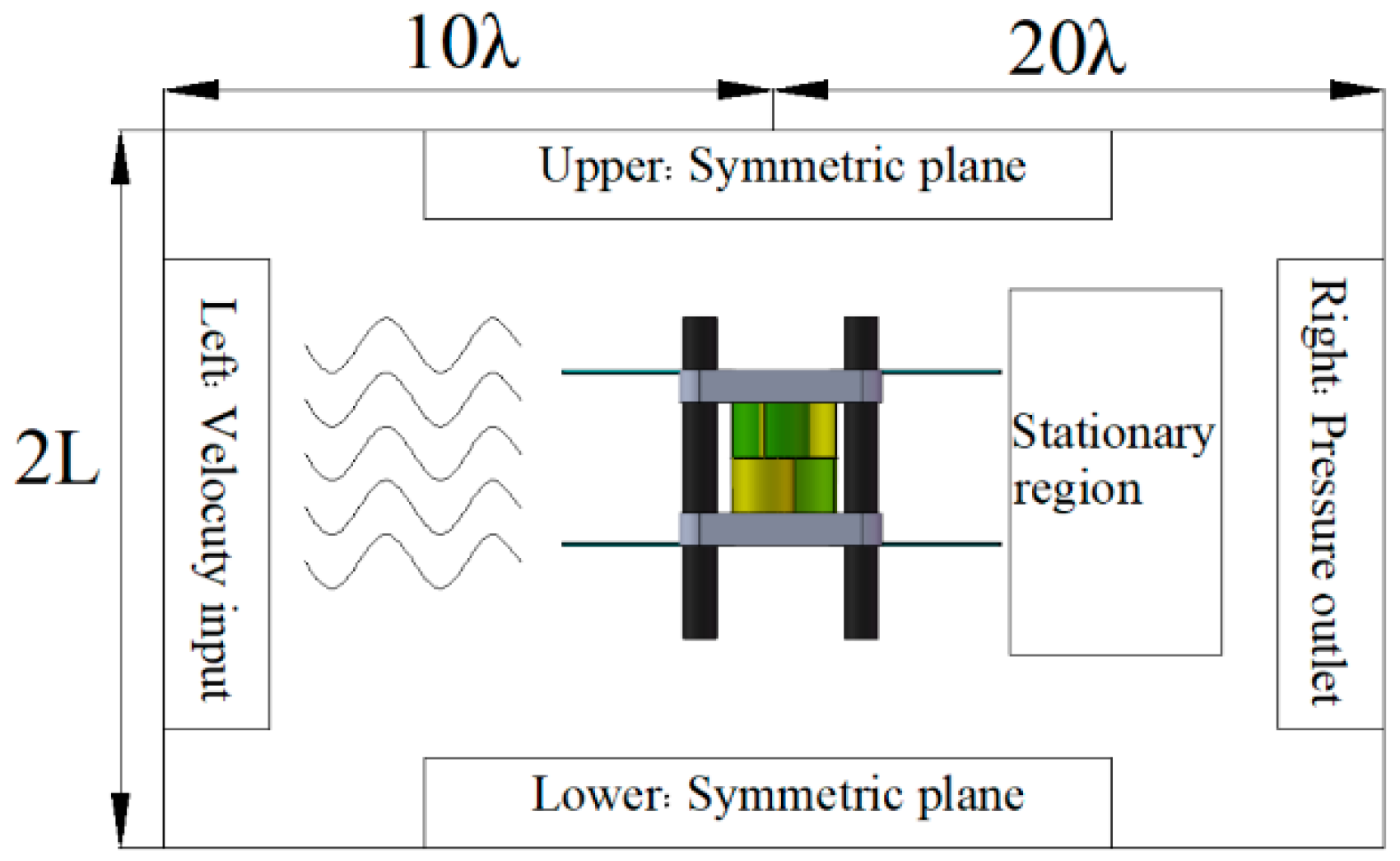
3.1. Simulation Domain Size and Boundary Conditions

Numerical simulations used an overset grid technique to simulate the movement of the floating breakwater. As shown in Figure 3, the entire simulation domain is divided into three distinct regions: the floating body region, the rotating region, and the background region. Both the floating body area and the rotating area are connected by an overlay grid interface and a background area. To avoid boundary conditions affecting the simulation results, the size of the computational domain needs to be set large enough. The simulation domain is 30λ long and 2L wide, and the floating breakwater is 10λ away from the left boundary. Typical boundary conditions are also used: the velocity inlet is set at the left boundary, and the incident wave is linear. The right boundary is set as the pressure outlet, and the upper and lower boundaries are set as the symmetry plane. The S-shaped runner and the floating body are set as wall surfaces. The numerical simulation scalar diagram is shown in Figure 4.

3.2. Meshing and Simulation Model Selection

The meshing of the computational domain is shown in Figure 5. The three regions are divided by two unstructured meshes: the tangential volume mesh and the prismatic layer mesh are applied to the rotation area, the floating body area, and the background area, respectively. In order to ensure the calculation accuracy of the rotating area and reduce the numerical transmission error, the grids of the rotating area and the floating body area are encrypted. On the other hand, eight prism layers are formed on the surface of the S-shaped runner to improve the mesh quality. The prism layer is extended to 1.1, and the volume growth rate is very slow. The fluid area grid is about 2.8 million, the rotation area is about 100,000, the pontoon area is about 180,000, and the total number of computational domain grids is set to 4,023,825.
Based on the RANS standard k ε   two-equation turbulence model, the two-layer model is realized by using the mixed wall processing function. The pressure interpolation of the control equation adopts the standard method and the second-order upwind style in the space discrete; the numerical solution uses pressure–velocity coupling: SIMPLE algorithm, with 50 internal iterations per time step, and a residual convergence criterion of 10−5. The rotation angle of the turbine must be less than 1° within a time step.

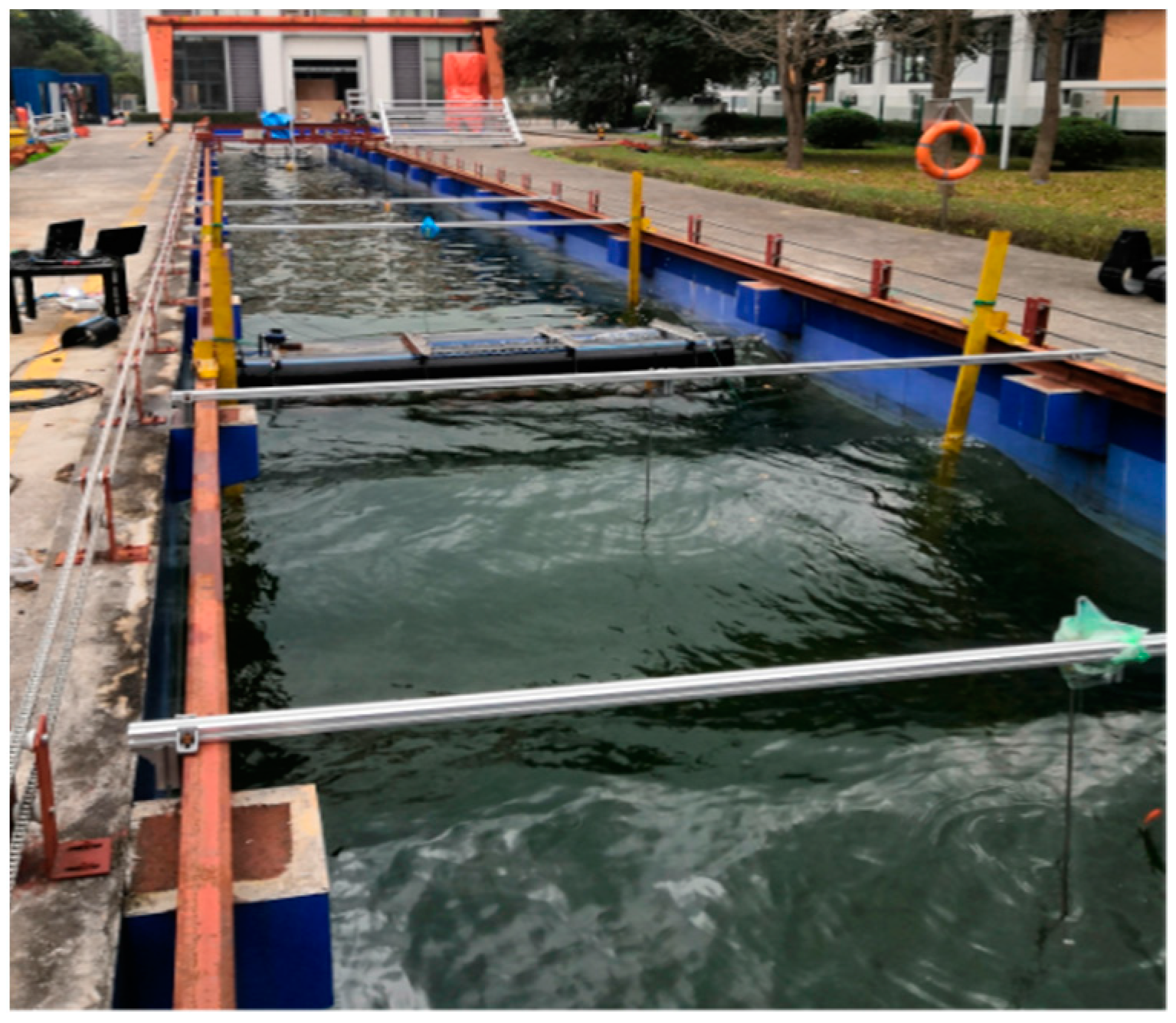
3.3. Simulation Validation

To verify the accuracy of the simulation model, the performance of the floating breakwater was tested in an experimental tank on the Ningbo campus of Zhejiang University. The experimental study of the flexible breakwater in the form of runner arrangement is based on the experimental water tank with a length of 70 m, a width of 4 m, and a depth of 2 m. A wave-making system is set on the left side of the sink, and a wave-eliminating net is set on the right side of the sink. The sensor collects the experimental data of the flexible breakwater, and the main measuring instruments: wave height meter and dynamic torque sensor. The digital wave height meter is installed at one wavelength and two wavelengths before and after the flexible breakwater, and the floating breakwater is located at more than ten wavelengths of the wave generator, and it can be clearly observed that the generated waves are stable. The experimental framework is shown in Figure 6.
The waves in the pool are linear waves with different periods, and the mooring method is multi-point tensioning. The S-type runner is immersed in water, and the breakwater performance of different runner arrangements is analyzed by changing the arrangement of the runners. Considering the instability of the incident wave and the attenuation and deformation of the waveform during wave-making, after the wave is stabilized, the number of continuously collected waves is more than 10, the collection time is more than 40 s, the data collection frequency is 50 Hz, and the average value is taken as the representative value. The wave is made by a rocking plate type wave generator, as shown in Figure 7, through the rotation of seven servo motors, the ball screw drives the seven wave-making plates to move, which can generate stable waveforms. The experimental arrangement is shown in Figure 8.

4. Results Analysis and Discussion

The main evaluation indicators of the wave-absorbing and energy-reducing performance of the floating breakwater based on the S-shaped runner are the change of the transmission coefficient and the energy consumption through the conversion of the S-shaped runner. The transmission coefficient is one of the important scales to measure the wave-absorbing performance of floating breakwaters. The smaller the transmission coefficient, the better the wave absorption performance, and the greater the power consumed by the S-type runner to convert the wave energy, the better the wave absorption performance. This research mainly starts from the structure of the floating breakwater. By studying the wave steepness h/λ, we can judge the wave absorption and energy reduction of the floating breakwater, and then change the distance between the floating pipes and the water entry depth of the S-shaped runner group. Considering the wavelength and wave height of the wave parameters, the relative parameters are taken, and the non-dimensional coefficients are used to study the wave elimination and energy conversion of the entire floating breakwater.

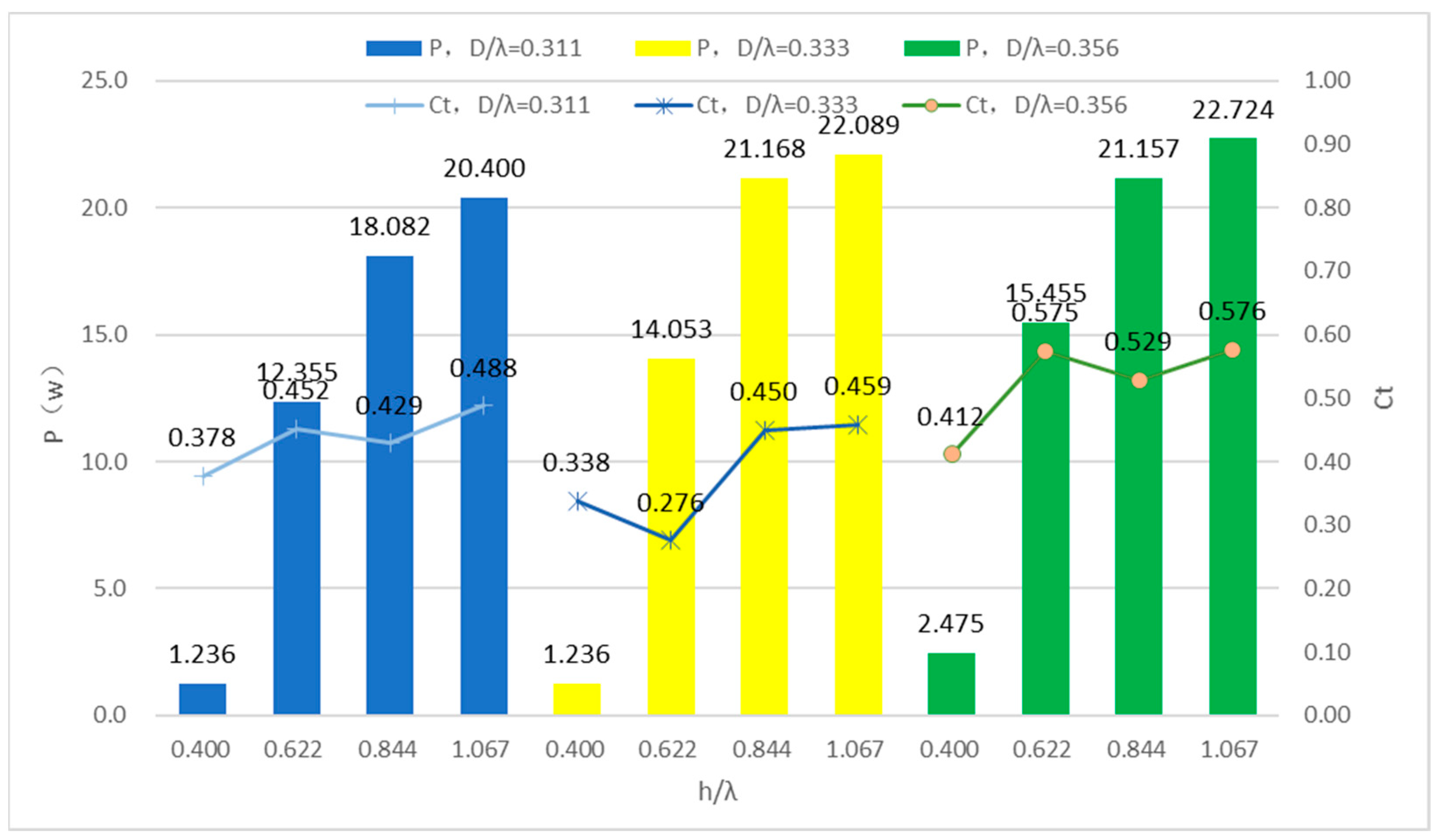
4.1. Influence of Wave Steepness h/λ

To study the effect of wave steepness h/λ on the performance of floating breakwater, the main research is to observe whether the energy of the incident wave affects the transmission coefficient and the power consumed by wave energy conversion. The combination of numerical simulation and physical experiment was adopted, and the research parameters are shown in Table 3.
Through numerical simulation, the numerical simulation data under three working conditions are compared, as shown in Figure 9. The power consumption of the S-type runner conversion under each working condition is gradually increased, and the transmission coefficient is between 0.3 and 0.6 fluctuation.
Through actual physical experiments, the data measured at the relative spacing W/λ = 0.267 are shown in Figure 10. The energy of the wave energy consumed by the conversion of the S-shaped runner increases with the increase of the wave steepness, and the growth trend is consistent with the trend of the numerical simulation.
In summary, the transmission coefficient fluctuates between 0.276 and 0.576. When the relative spacing W/λ and the water entry depth D/λ relative to the wavelength are consistent, the power consumed by the wave energy conversion of the S-type runner increases with the wave steepness h/λ increasing.
According to the data analysis, as shown in Figure 11, the standard deviation of the transmission coefficient does not change drastically due to the changes of the water entry depth D/λ and the wave steepness relative to the wavelength, and it always keeps a low value. The conversion power of the S-type runner to the wave energy. The standard deviation of P is relatively large, especially when the water entry depth relative to the wavelength D/λ = 0.34; the wave steepness has a great influence on the energy conversion power of the S-shaped runner.
It can be seen from Figure 12 that under different wave steepness h/λ working conditions, the water penetration depth D/λ relative to the wavelength also does not cause a huge change in the standard deviation of the transmission coefficient, and the standard deviation of the energy conversion power of the S-type runner is less than 1.6. Therefore, the impact of the water entry depth D/h relative to the wave height is greater than the effect of the water entry depth D/λ relative to the wavelength of the floating breakwater.

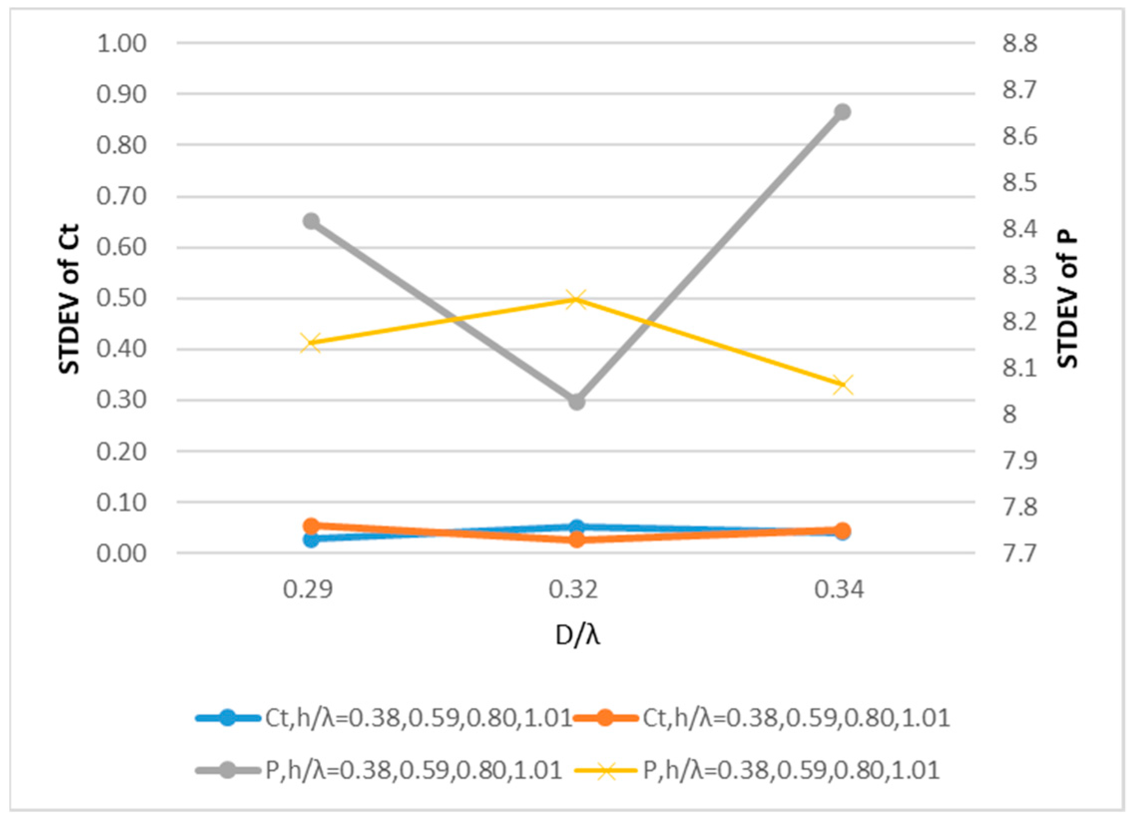
4.2. Influence of Water Entry Depth D/λ with Respect to Wavelength

The water penetration depth D/λ relative to the wavelength is a variable based on the ratio of the water penetration depth of the S-type runner to the wavelength. To verify the influence of the water penetration depth relative to the wavelength, a combination of numerical simulation and physical experiments is also used for analysis and research. Set the spacing between the floating tubes to be 0.7 m, the relative width to be 0.29, and the wave steepness h/λ to be 0.38, 0.59, 0.80, and 1.01, respectively, for numerical simulation experiments.
It can be seen from Figure 13 that under different wave steepness h/λ conditions, the transmission coefficient fluctuates between 0.4 and 0.6, and the power consumption of wave energy conversion increases significantly with the increase in wave steepness h/λ. The influence of the type of runner is greater. Under the same working conditions, the water entry depth D/λ relative to the wavelength has no significant effect on the change of the S-type runner and the transmission coefficient.
At the same time, the method of the physical experiment was used to compare the experimental data of the spacing between floating tubes of 0.7 m, the relative spacing of 0.34, and the wave steepness h/λ of 0.38, 0.59, 0.80, and 1.01, respectively, as shown in Figure 14.
When the relative spacing W/λ and wave steepness h/λ are the same, with the increase in the water entry depth relative to the wavelength, the conversion power first increases and then decreases, and the transmission coefficient fluctuates between 0.4 and 0.65.

4.3. Influence of Water Entry Depth D/h Relative to Wave Height

The wave absorption and energy reduction performance of the floating breakwater based on the S-shaped runner is studied, and the relative width of the control remains unchanged. For the water entry depth D/h relative to the wave height as a variable, the value of the water entry depth D/h relative to the wave height is S The ratio of the relative water entry depth of the type of runner to the wave steepness h/λ, and the same wavelength is guaranteed, the formula is deduced as follows.
D h = D λ h λ
When the relative width is 0.252, with the increase in the D/h coefficient of the water entry depth relative to the wave height, the power consumption of wave energy conversion decreases significantly, and the coefficient conversion power value per unit also changes significantly in Figure 15.
When the relative width is 0.294, with the increase in the water entry depth D/h relative to the wave height, the power consumption per unit of wave energy conversion also gradually decreases, which is the same as the trend of the working condition when the relative width is 0.252. At the same time, it can be found that the transmission coefficient is relatively stable, fluctuating around 0.5, and the fluctuation error is ± 0.1 in Figure 16.
Considering the installation size of the S-shaped runner and the floating tube and preventing the incident wave from being broken due to excessive wave steepness h/λ, the research and analysis of the water entry depth D/h relative to the wave height starts from 0.29. The power consumption of wave energy conversion increases with the coefficient relative to the wave height shows a trend of rising first and then decreasing. The deeper the water entry depth of the S-type runner, the smaller the impact of waves on the S-type runner due to the viscosity of the water. The coefficient of the water entry depth D/h relative to the wave height is one of the important factors of the power consumption of wave energy conversion.

4.4. Effect of Relative Spacing W/λ

For the study of the relative spacing W/λ, the data changes under different working conditions are studied by means of physical experiments. Through the comparative analysis of the transmission coefficient, when the relative spacing is 0.267, the transmission coefficient is relatively the largest, and the wave absorption performance is relatively poor. With the increase in the relative distance, the transmission coefficient has a tendency to decrease or become stable. When the transmission coefficient decreases sharply, the wave absorption performance is the best, and the power consumption of the energy conversion of the S-type runner is also the lowest. This is because the S-type runner will stall with the increase in the relative distance, and the wave energy acts on the on the entire breakwater in Figure 17.

5. Conclusions

Through the numerical simulation and physical test, the following conclusions can be drawn from this research:
  • Under the action of linear waves, when the relative spacing W/λ of the floating breakwater and the water entry depth D/λ relative to the wavelength remain unchanged, the energy conversion power of the S-type runner increases with the wave steepness h/λ. The greater the wave steepness h/λ, the greater the energy input into the floating breakwater, and the greater the energy consumed by the floating breakwater. The transmission coefficient fluctuates between 0.3 and 0.6.
  • For the study of the water entry depth D/h relative to the wave height, the power consumption of the S-type runner wave energy conversion increases first and then decreases with the coefficient relative to the wave height. The deeper the water entry depth of the S-type runner, the smaller the impact of waves on the S-type runner due to the viscosity of the water. The coefficient of the water entry depth D/h relative to the wave height is one of the important factors for the power consumption of wave energy conversion. The transmission coefficient is relatively stable, fluctuating around 0.5.
  • For the study of relative spacing W/λ, the transmission coefficient of waves will show a trend of decreasing at first and then tending to fluctuate smoothly with the increase of relative spacing W/λ. For the water entry depth D/λ relative to the wavelength, the wavelength factor does not cause an increase in the power consumption of the wave energy converted by the S-type runner.

Author Contributions

Conceptualization, Y.W. and L.B.; methodology, L.B.; validation, L.B. and Y.W.; formal analysis, L.B.; data curation, L.B. and C.J.; writing—original draft preparation, L.B.; writing—review and editing, Y.W.; visualization, C.J. and S.W.; supervision, H.L.; project administration, J.C. and Y.W.; funding acquisition, J.C. and Y.W. All authors have read and agreed to the published version of the manuscript.

Funding

This research was co-funded by three projects: the Ministry of National Key R&D Project of the People’s Republic of China Science and Technology Fund, Approval No. 2020YFE0200100; and Ningbo Municipal Science and Technology Innovation 2025 Major Project, 2020Z076; Ningbo Municipal Major Science and Technology Research and Unveiling Project, 20212ZDYF020015.

Institutional Review Board Statement

Not applicable.

Informed Consent Statement

Not applicable.

Data Availability Statement

Not applicable.

Conflicts of Interest

The authors declare no conflict of interest.

References

  1. Dai, J.; Wang, C.M.; Utsunomiya, T.; Duan, W. Review of recent research and developments on floating breakwaters. Ocean. Eng. 2018, 158, 132–151. [Google Scholar] [CrossRef]
  2. Shih, R.S.; Weng, W.K.; Chou, C.R.; Chou, C. The performance characteristics of inclined highly previous pipe breakwaters. Ocean. Eng. 2015, 100, 54–66. [Google Scholar] [CrossRef]
  3. Wang, H.; Xu, H.; Liu, P. Experimental study on the dissipation characteristics of curtain-type flexible floating breakwater. J. Coast. Res. 2015, 73, 410–414. [Google Scholar] [CrossRef]
  4. Syed, S.A.; Mani, J.S. Performance of rigidly interconnected multiple floating pontoons. J. Nav. Archit. Mar. Eng. 2004, 1, 2031. [Google Scholar] [CrossRef] [Green Version]
  5. Rahman, A.; Miautani, N.; Kawasaki, K. Numerical Modeling of Dynamic Responses and Mooring Forces of Submerged Floating Breakwater. Coast. Eng. 2006, 53, 799–815. [Google Scholar] [CrossRef]
  6. Bayram, A. Experimental Study of a Sloping Float Breakwater. Ocean. Eng. 2000, 27, 445–453. [Google Scholar] [CrossRef]
  7. Yu, J.; Chen, J.H.; Yao, J.J.; Li, F.S.; Miao, B.Y. Numerical research on the hydrodynamic performance of a new-type floating breakwater. Ocean. Eng. 2019, 37, 62–73. [Google Scholar] [CrossRef]
  8. Yao, J.J.; Li, F.S.; Wang, X.C.; Su, Z.X.; Yu, J. Numerical simulation study of the Savonius turbine on the current reduction characteristics. J. Harbin Eng. 2020, 41, 1–8. [Google Scholar] [CrossRef]
  9. Yao, J.J.; Li, F.S.; Chen, J.H.; Su, Z.X.; Yu, J. Research on a vertical-axis drag-type Savonius hydrokinetic turbine. J. Harbin Eng. Univ. 2019, 41, 298–308. [Google Scholar] [CrossRef]
  10. Ji, C.Y.; Bian, X.Q.; Cheng, Y.; Yang, K. Experimental study of hydrodynamic performance for double-row rectangular floating breakwaters with porous plates. Ships Offshore Struct. 2019, 14, 8521. [Google Scholar] [CrossRef]
  11. Ji, C.Y.; Zheng, R.S.; Cui, J.; Wang, Z.L. Experimental Evaluation of Wave Transmission and Dynamics of Double-Row Floating Breakwaters. J. Waterw. Port Coast. Ocean. Eng. 2019, 145, 515. [Google Scholar] [CrossRef]
  12. Ji, C.; Deng, X.; Yong, C. An experimental study of double-row floating breakwaters. J. Mar. Sci. Technol. 2018, 24, 359–371. [Google Scholar] [CrossRef]
  13. Zheng, R.S. Design and Hydrodynamic Performance Study of Integrated Floating Breakwater and Wind Power Generation. Master’s Thesis, Jiangsu University of Science and Technology, Zhenjiang, China, 2019. [Google Scholar]
  14. Cong, G. Experimental Study on Performance of Raft Floating Breakwater under the Action of Relatively Long Period Waves. Master’s Thesis, Dalian University of Technology, Dalian, China, 2019. [Google Scholar] [CrossRef]
  15. Zhang, Y.; Li, M.; Zhao, X.; Chen, L. The effect of the coastal reflection on the performance of a floating breakwater-WEC system. Appl. Ocean. Res. 2020, 100, 102117. [Google Scholar] [CrossRef]
  16. Qu, K.; Sun, W.Y.; Kraatz, S.; Deng, B.; Jiang, C.B. Effects of floating breakwater on hydrodynamic load of low-lying bridge deck under impact of cnoidal wave. Ocean. Eng. 2020, 203, 107217. [Google Scholar] [CrossRef]
  17. Zhang, H.M.; Ding, X.C.; Zhou, B.Z.; Zhang, L.; Zheng, Y. Hydrodynamic performance study of wave energy-type floating breakwater. J. Mar. Sci. Appl. 2019, 18, 64–71. [Google Scholar] [CrossRef]
  18. Bao, L.J.; Peng, T.H.; Huang, F.P.; Lei, Z.; Zuan, L. Numerical simulation and experimental study on a new type of energy absorption and wave elimination floating breakwater. Port Waterw. Eng. 2020, 4, 9–14. [Google Scholar] [CrossRef]
  19. Huang, F.P.; Gong, K.; Liu, Z.S.; Chen, J.H.; Huang, Y.C. Experimental Research on A New Type of Floating Breakwater for Wave-Absorbing and Energy-Capturing. China Ocean. Eng. 2020, 34, 817–827. [Google Scholar] [CrossRef]
Figure 1. Savonius type runner.
Energies 15 05148 g001
Figure 2. Physical model of s-type runner.
Energies 15 05148 g002
Figure 3. Computational Domain and Boundary Conditions.
Energies 15 05148 g003
Figure 4. Flow field scalar diagram.
Energies 15 05148 g004
Figure 5. Grid division diagram.
Energies 15 05148 g005
Figure 6. Sketch of floating breakwater.
Energies 15 05148 g006
Figure 7. Wave-making system.
Energies 15 05148 g007
Figure 8. Testing site.
Energies 15 05148 g008
Figure 9. Simulation experiment data graph with h/λ as variable.
Energies 15 05148 g009
Figure 10. Physical experiment data map.
Energies 15 05148 g010
Figure 11. Standard deviation analysis plot with D/λ as variable.
Energies 15 05148 g011
Figure 12. Standard deviation analysis plot with h/λ as variable.
Energies 15 05148 g012
Figure 13. Experimental data graph.
Energies 15 05148 g013
Figure 14. Plot of experimental data with D/λ as variable.
Energies 15 05148 g014
Figure 15. Experimental data graph.
Energies 15 05148 g015
Figure 16. Data analysis diagram.
Energies 15 05148 g016
Figure 17. Plot of experimental data with W/λ as variable.
Energies 15 05148 g017
Table 1. Geometric characteristics of floating breakwater.
ParameterNumerical Value/m
floating tube diameter0.33
floating tube spacing0.65
float length3
wheel diameter0.5
blade radius0.15
wheel height0.61
Table 2. Hydrodynamic parameters of floating breakwater.
ParameterValueUnit
water depth5m
draft1.7m
HDPE float density0.95kg/m3
runner displacement10kg
wheel inertia moment(0.337, 0.337, 0.16)kg·m2
Table 3. Parameter table of wave steepness research.
ParameterW/λD/λh/λMethods
value0.2740.320, 0.343, 0.3660.412, 0.640, 0.869, 1.098numerical simulation
0.2670.311, 0.333, 0.3560.400, 0.622, 0.844, 1.067physical experiment
Publisher’s Note: MDPI stays neutral with regard to jurisdictional claims in published maps and institutional affiliations.

