Article

A Study on the Safety Analysis of an Inductive Power Transfer System for Kitchen Appliances

School of Electrical Engineering & Automation, Harbin Institute of Technology, Harbin 150001, China
*
Author to whom correspondence should be addressed.
Energies 2022, 15(14), 5218; https://doi.org/10.3390/en15145218
Submission received: 9 June 2022 / Revised: 7 July 2022 / Accepted: 11 July 2022 / Published: 19 July 2022

Abstract

:
This paper presents a detailed analysis of the safety of human bodies in the electromagnetic field generated by inductive power transfer (IPT) systems designed for kitchen appliances. Comparisons of basic and reference limit values of various safety standards are investigated through theoretical circuit analysis and extensive simulation studies. Simulation models of human bodies along with an IPT system for kitchen appliances are established to reveal the effect of the electromagnetic field on the human body. Corresponding experiments are conducted via constructing a configuration of the designed IPT system and simulating the standing position. Both experimental and analytical results indicate that it is easier to fulfill international safety standards by increasing the operating frequency of the IPT system for kitchen appliances, and hence, the safety of human bodies can be effectively improved.

1. Introduction

With the continuous improvement of people’s quality of life, electronic equipment and household appliances are gradually diversified. The messy wires and sockets are unsightly and greatly reduce the convenience of use. Moreover, the long-term used wires will inevitably suffer from wear and tear [1]. The aging phenomenon is extremely prone to safety accidents. IPT technology enables household appliances to be tailless, greatly reducing the number of wires and reducing the risk of electric shock [2,3].
Because of the specific application environment, the safety of IPT technology adopted in household appliances for the human body is of great concern. Compared with tangible damage, the space electromagnetic field affects the surface tissues or neurons of the human body and may not be sensed in time during the application process. For example, the specific absorption rate (SAR) is a continuous impact process. Since 1960, some international organizations or countries have started to introduce electromagnetic radiation safety standards and specifications. At present, the two main international safety-standard-setting institutions include the International Commission for Non-Ionizing Radiation Protection (ICNIRP) and the Institute of Electrical and Electronic Engineering (IEEE) proposing the ICNIRP 1998, 2010, 2018 guidelines [4,5] and IEEE C95.1 1992, 2005, 2019 standards [6,7], respectively. The regional standards adopted by different countries are different. The main factors involved in safety standards include the magnetic field strength (MFS), electric field strength (EFS), magnetic induction strength, current density, power density, and SAR value. Figure 1 shows the reference limit curve of the MFS and EFS of various standards. The standards proposed by the International Electrotechnical Commission (IEC) serve as important reference materials for the European Electronics Technical Standards Committee to provide the corresponding European standards (EN). Local standards are only adopted as a reference and comparison, such as EN 62311, which is based on the standard set by IEC 62311 [8]. However, IEC 62311 defines measurement procedures rather than limit values. These procedures are normative, whereas the limit values are informative. The IEC/EN 62311:2020 standard is mainly adopted in Europe for evaluating the human body in electromagnetic fields, where the reference threshold range is completely consistent with that in ICNIRP 1998. The safety evaluation standard for electromagnetic fields generated by kitchen appliances is IEC/EN 62233:2008. Regarding the reference limit of EFS and MFS, the frequency range of ICNIRP 1998 is 1 Hz–300 GHz; the frequency range of ICNIRP 2010 is 1 Hz–10 MHz; the frequency range of ICNIRP 2018 is 100 kHz–300 GHz; the frequency range of IEEE C95.1 2005 is 1 Hz–300 MHz. It can be summarized that compared with ICNIRP 2010 and 2018, ICNIRP 1998 is more critical in the full frequency domain, while ICNIRP 2018 and ICNIRP 2010 complement each other and cover the full frequency domain safety standard. The 2018 version revised the 2010 version of the limit above 100 kHz. Scholars have paid some attention to the analysis of such related standards. Kalialakis et al. [7] have summarized the security-standard-setting agencies and their main functions of various fields, organizations, and countries by comparing the application fields of IPT technology. Although wireless power products have not been fully commercialized, the security standards of different frequencies and powers have been basically mature, and when designing products of different power levels, priority should be given to the safety limit of frequency. De Santis et al. [9] discussed the difference between the basic limits of ICNIRP 1998 and 2010 in the low-frequency range (below 100 kHz) in detail and explained the influence of the internal induced EFS on the human nervous system in the electromagnetic field environment compared with the surface current density, which explained the main function of electric field intensity E 99th . By comparing different electric field intensity calculation methods, E 99th is proven to be appropriate as the reference parameter of the basic restriction. Christ et al. [10] further compared the frequency and safety limits between ICNIRP 1998, 2010, and IEEE C95.1 2005 in detail.
Relatively speaking, although the IEEE safety standards were proposed first, the corresponding standards proposed by ICNRIP are more widely recognized by institutions because of the wider frequency coverage and stricter quantification of basic and reference limits. Since the introduction of EFS E 99th in the 2010 version, the quantification of the limits of different tissues in the human body is more accurate and provides a higher reference value. Recent research on the impact of IPT systems on human safety mainly include charging for electric vehicles [11,12,13,14], implant medical devices [15,16,17,18], and so on. Shimamoto et al. [11] investigated the electromagnetic dosimetry of an adult male model exposed to the magnetic field leaked from an IPT system located in an electric vehicle. Sunohara et al. [15] investigated the in situ electric field (E-field) and SAR in human models. Laakso et al. [12] discussed the applicability of a novel H-field measurement at various heights for safety compliance. Chen et al. [19] examined human exposure in terms of induced peak E-field and SAR in a WPT scenario with various operating frequencies. However, only general standing postures were considered in these studies. Furthermore, in some specific applications such as implant devices and household appliances, the effects of IPT devices on human tissues and organs with respect to various power levels and distances are also important. Compared with other applications such as implant medical devices and electric vehicles, the operating conditions and safety evaluation of the household application are quite different. The compared results are listed in Table 1.
In summary, there is still no corresponding standard for the safety design and evaluation of tailless kitchen appliances. In addition, the limit index of the EFS and MFS below 100 kHz is necessary and worthy of attention. In this paper, we mainly focus on the safety of tailless kitchen appliances for the human body. Specifically, we start with the modeling of both the IPT system designed for kitchen appliances and the calculation of basic limit values. The effect of tailless kitchen appliance system on the human body at various operating frequencies and power levels, based on different safety standards, is analyzed in detail in Section 3. Experimental results are given in Section 4. Finally, Section 5 concludes the paper.

2. Modeling

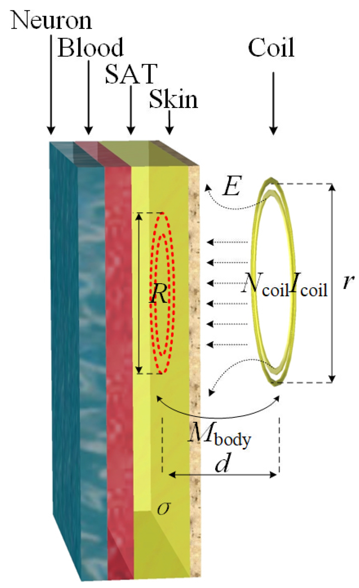
2.1. Equivalent IPT Model

When designing an IPT system for kitchen appliances, because of the diversity of load appliances, the basic series–series (SS) compensated topology is adopted here to meet the requirement of source versatility. The equivalent circuit model of the designed IPT system is shown in Figure 2. U i and U o are the system input and output voltage. L P and L S are inductors of the transformer at the primary and secondary sides and C P and C S are the corresponding compensation capacitors. M represents the mutual inductance between the primary and secondary sides, and M = k L P L S , where k denotes the coupling coefficient. R p and R s denote the equivalent series resistance (ESR) at the primary and secondary sides. R L represents the equivalent resistance of the load. According to Kirchhoff’s voltage law, the equation of the state matrix of the IPT system can be obtained as
U i ˙ 0 = Z P j ω M j ω M Z S I P ˙ I S ˙
where ω denotes the operating frequency. I P and I S represent the primary and secondary current. Then, the input power P i can be expressed as
P i = U i I P = U i 2 Z in
where Z in = Z P + ω 2 M 2 Z S . Z P and Z S are the equivalent impedance of the primary and secondary side. When the system operates at resonance frequency, Z P = R p , Z S = R s . In this case, the system output power P o can be obtained as
P o = ω 2 M 2 I p 2 R L R L + R s 2

2.2. Modeling of Basic Restrictions

According to the ICNIRP 2010 standard, the in situ electric field can be vector averaged over a voxel of 2 × 2 × 2 mm 3 . The sum of the EFS within a voxel can then be expressed as
E r 0 V = 1 V n E ( r n ) f n V n
where r 0 denotes the voxel center. V denotes the average volume of 8 mm 3 . V n denotes the volume value of the nth percentile inside the voxel. E r 0 represents the value of the electric field intensity in V n centered on r n . f n denotes the filling factor, and generally, 0 < f n < 1. The filling factor depends on the voxel size of the overall grid divided by the system and mainly contributes to supplement the volume of the voxel at the distance or the edge for satisfying the condition of the average volume.
According to the IEEE C95.1 standard, in the direction of the electric field vector in the human body tissue of the in situ electric field, a length of 5 mm is considered as a division unit. To achieve the average of the spatial electric field along the 5 mm straight line, the length of the dividing line is represented by L, which is cut by the spatial electric field vector in the voxel, with r 0 as the center point. The spatial average intensity of the electric field can then be described as
E r 0 L = l ^ 0 L L E ( r ) · l ^ 0 d l = K L l ^ 0
where L is designed to the average length of 5 mm. K represents the integral value of electric field intensity along the dividing line. l ^ 0 represents the unit vector of electric field space, and l ^ 0 = E ( r 0 ) E ( r 0 ) .
Comparing the average value of the space electric field based on the ICNIRP standard with the IEEE standard, it can be observed that the ICNIRP standard is the volumetric average of the space electric field, while the IEEE standard is the line integral average of the space electric field.
Since the ICNIRP 1998 standard is still adopted in several countries, the basic limit current density permits an important reference. The density J ( r 0 ) of current I s passing perpendicularly through a unit surface S of 1 cm 2 can be expressed as
J ( r 0 ) S = 1 A S J ( r ) · n ^ 0 d S = I s π R 2 n ^ 0
where n ^ 0 represents the direction of the current vector. A denotes a certain surface area, and R is the equivalent radius of this surface area, i.e., A = π R 2 .
According to Ohm’s law and Faraday’s law of electromagnetic induction, the current density J can be further expressed as
J = π R σ f B
where σ denotes the conductivity of human tissue. It can be readily observed from Equation (7) that the density of the induced electric field is proportional to the product of frequency f and magnetic induction strength B. According to the aforementioned IPT circuit in Figure 2, the square wave resonance voltage U P can be expanded by Fourier series as follows:
U P = 4 U i π n = 1 sin ( ( 2 n 1 ) ω t ) 2 n 1 , n = 1 , 2 , 3 ,
Furthermore, the primary resonance current I P can be expressed as
I P = π 2 I i sin ( ω t )
According to Faraday’s law of electromagnetic induction, the spatial magnetic field generated by the transmitting or receiving coil can be described as
N P I P = H l = B l μ r μ 0 = ϕ l μ π R 2
where N P denotes the number of primary coil turns. H denotes the spatial magnetic field intensity. l denotes the length of the closed magnetic circuit. B denotes the magnetic induction intensity, and B = μ 0 μ r H . R denotes the coil radius. ϕ denotes the coupling magnetic flux on the secondary side; μ denotes the permeability, and μ = μ 0 μ r . Illustrated in Figure 3 is the relationship between human issue and coupling coils. Thus, the induced voltage E of the secondary coil can be expressed as
E = N S ω ϕ = π μ N S ω N P I P R 2 l
where N S represents the number of secondary coil turns.

3. Analysis of Safety to Human Body

In this section, the Sim4Life simulation software is utilized to simulate real working conditions in which the human body is exposed to the spatial electromagnetic field of the IPT system and to analyze whether the human body meets the standard under various frequency ranges, power, and distance conditions according to the limits of various safety standards.
An Asian female human body model was established, with the specific parameters shown in Table 2. By calculating the weight and volume ratios of various parts of the human body, the Subcutaneous adipose tissue (SAT) and visceral adipose tissue (VAT) of the human body accounts for 49.4% of the total body mass and 54.38% of the total volume. The eddy current loss caused by exposure to spatial electromagnetic fields is also mainly concerned in this paper.
Based on the statistical general size of various commercially available electrical appliances, a simulation model of the IPT system that meets the standard is established, while limiting the output power and operating frequency range of the system. The specific parameters of the system are listed in Table 3, and a schematic of the magnetic coil adopted in the system is shown in Figure 4. Based on Equation (3), the control of output power can be achieved via the regulation of resonant current I P . The resonant current values calculated according to different output power conditions at various frequency are set as shown in Table 4.

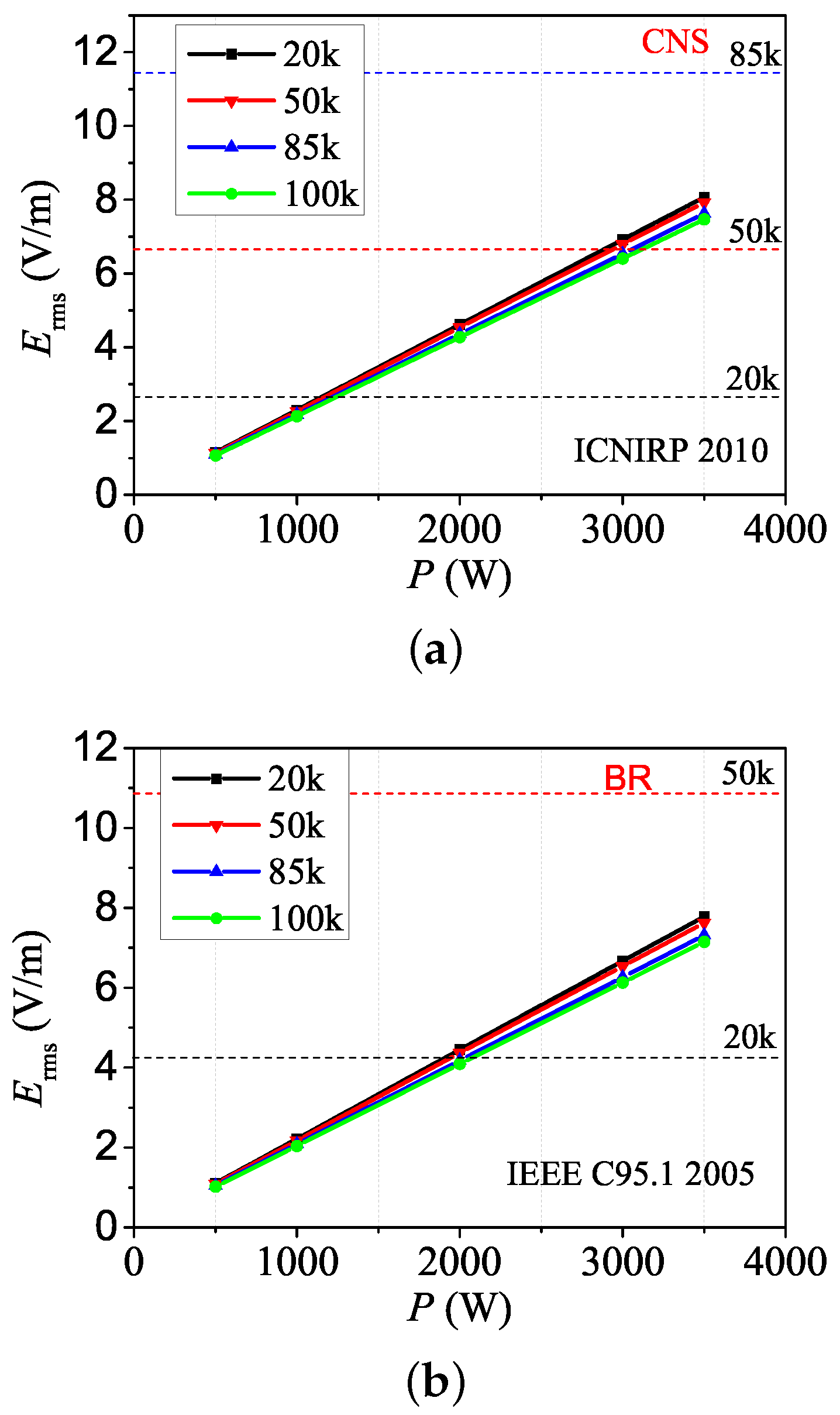
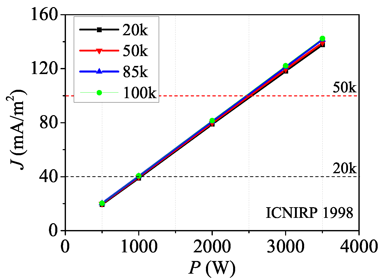
3.1. Different Frequency and Power

It can be observed from Figure 5 that as the power increases, the MFS increases as the human body is affected by space EMF radiation. Comparing the four different international standards for ionizing radiation, IEEE C95.1-2005 is the least restricted. Even at a maximum output power of 3.5 kW, the reference limit of 163 A/m in this standard is not exceeded in the case of the immediate vicinity of the transmitter. EN 62311-2020 has a similar reference limit as ICNIRP 1998. As a major European electrical standard, the MFS is 5 A/m in EN 62311-2020, which is stricter than the 2010 version. In addition, Figure 5 also explicates that when the system operates at 20 kHz, the MFS to the human body exceeds the ICNIRP 21 A/m restriction of the 2010 standard when the output power exceeds 1 kW. When the system operates at 50 kHz, the MFS reference level will not be exceeded until the output power reaches 2.5 kW.
In order to compare the basic limit values of various standards, we directly capture the maximum value E max of the internal EFS of the human body by simulation. Since the basic restriction of the EFS in both the ICNIRP and IEEE standards is the valid value E rms and the resonant current in the presented system is a standard sine wave, the relationship between E rms and E max can be readily obtained, i.e., E rms = E max 2 . Using this conversion formula, Figure 6 illustrates the internal EFS values calculated according to the ICNIRP 2010 standard and IEEE C95.1-2005 standard, respectively. According to the requirements of the basic restriction at different frequencies, the limit value of ICNIRP 2010 is significantly lower than that of IEEE C95.1, which means the former is relatively more critical. Comparing Figure 5 and Figure 6 and taking the case of operating at 50 kHz as an example, it can be observed that when the MFS reaches the reference limit value of 21 A/m, the output power achieves 2.5 kW, while the EFS reaches the basic restriction of 6.75 V/m, and the output power of the system is 3 kW. This means that when the safety standard is evaluated on the basis of the reference limit value, the data are always below the safety standard threshold value of the basic restriction and do not affect the evaluation result. When the strength of the external magnetic field exceeds the reference limit value, there exists a possibility that it does not exceed the basic restriction and is within the limits of human safety.
In addition to the value E rms , another value, E 99th , which represents the 99th percentile value of the induced electric field in the human body after numerical statistics and arrangement, is also included in ICNIRP 2010. Figure 7 explicates the comparison of the results of these two values changing with output power and operating frequency. It can be observed that there exists a large gap between the E 99th and E rms values, because E 99th depends on the conditions of various human organs, while E rms depends on the maximum EFS of all the human organs. Moreover, Figure 7 shows that the values E 99th are the same at various frequencies and increase linearly with power. This means that the internal EFS of the human body is only positively related to the output power and is independent of the operating frequency, i.e.,
E 99th = K P o = A f B
where K and A represent the scale coefficient and the compensation coefficient, respectively. B represents the MFS of the human body.
According to the ICNIRP 1998 standard, which has been revised to the ICNIRP 2010 standard, surface current density J is adopted as the basic restriction. Since the 1998 version is still applicable in some countries, it is meaningful to include this parameter in the analysis, and for a comparison of the basic limits, a corresponding simulation is carried out to compare the mathematical models of the two basic limit values, as shown in Figure 8. It can be readily observed that with the increase in power level, the surface current density J rms of the human body increases linearly and changes little with frequency. The simulation results match well with the theoretical analysis in Equation (7), i.e., when the output power is constant ( f B is constant), the surface current density J rms remains unchanged, i.e., J rms = Q P o , where Q is the scale coefficient.
In addition, comparing Figure 7 and Figure 8, for example, when the output power reaches 2.7 kW in ICNIRP 1998 with a 50 kHz frequency, the limit value of 100 mA/m2 is exceeded; in ICNIRP 2010 with the same frequency, when the output power reaches 3 kW, the limit value of 6.75 V/m is exceeded. This means that the limits of current density J rms in ICNIRP 1998 are tighter than the limits of EFS E rms in ICNIRP 2010.
For the requirements on the basic limit SAR value, both ICNIRP and IEEE indicate that the calculation and analysis of the SAR value is required when operating at frequencies above 100 kHz. It can be obtained from Figure 9 that the human body SAR value is positively correlated with the square of output power, and the SAR value is basically the same at different frequencies with the same power level. Simulation results show that in the the low frequency stage (20 kHz–100 kHz), the SAR-1g and SAR-10g values of the effect of electromagnetic fields on the human body at different powers are much lower than the whole body SAR value requirement of 0.08 W/kg.
Furthermore, comparing the two figures depicted in Figure 9, SAR-1g is always greater than SAR-10g at various output power levels, and the gap becomes consistently wider as the power increases.

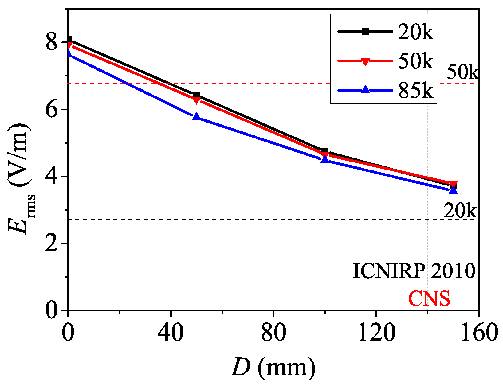
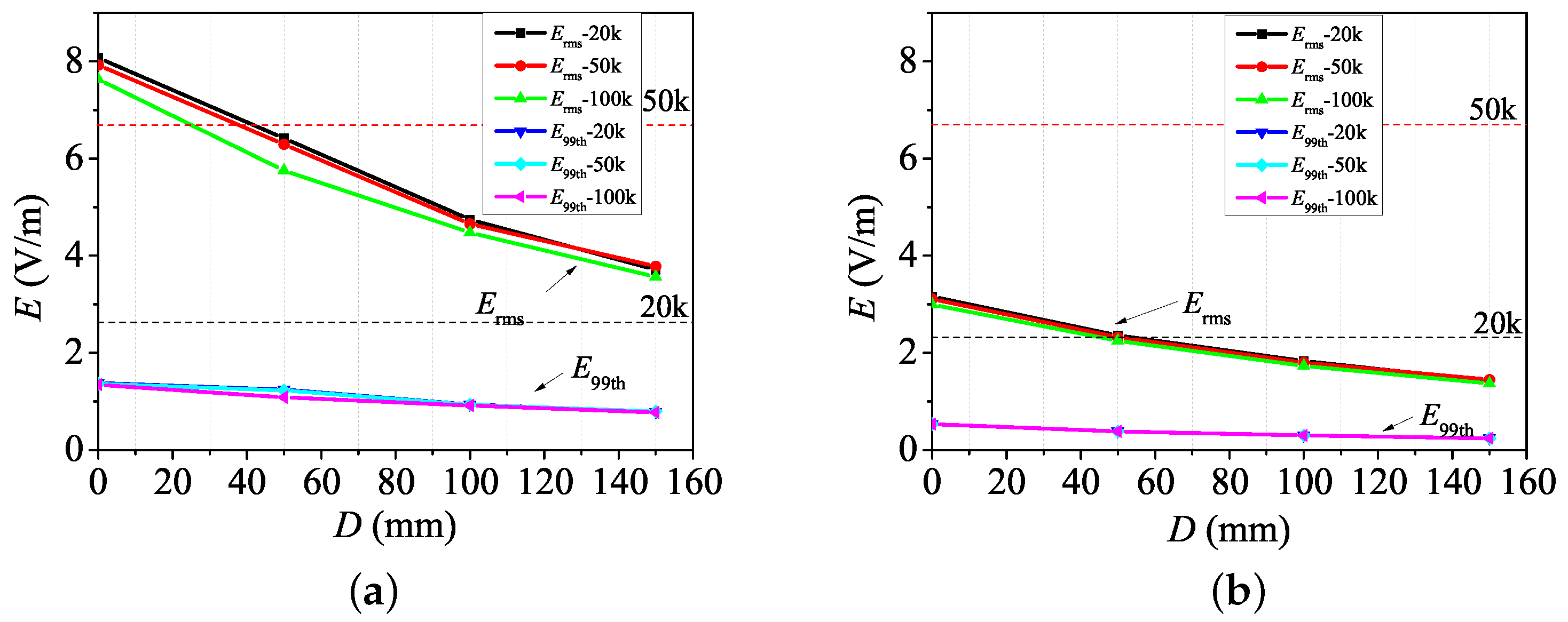
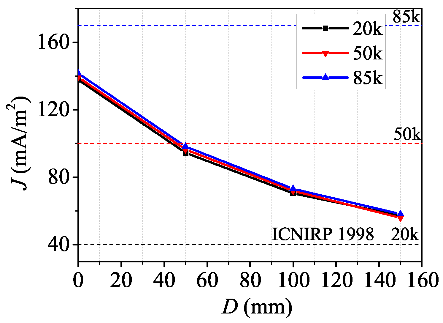
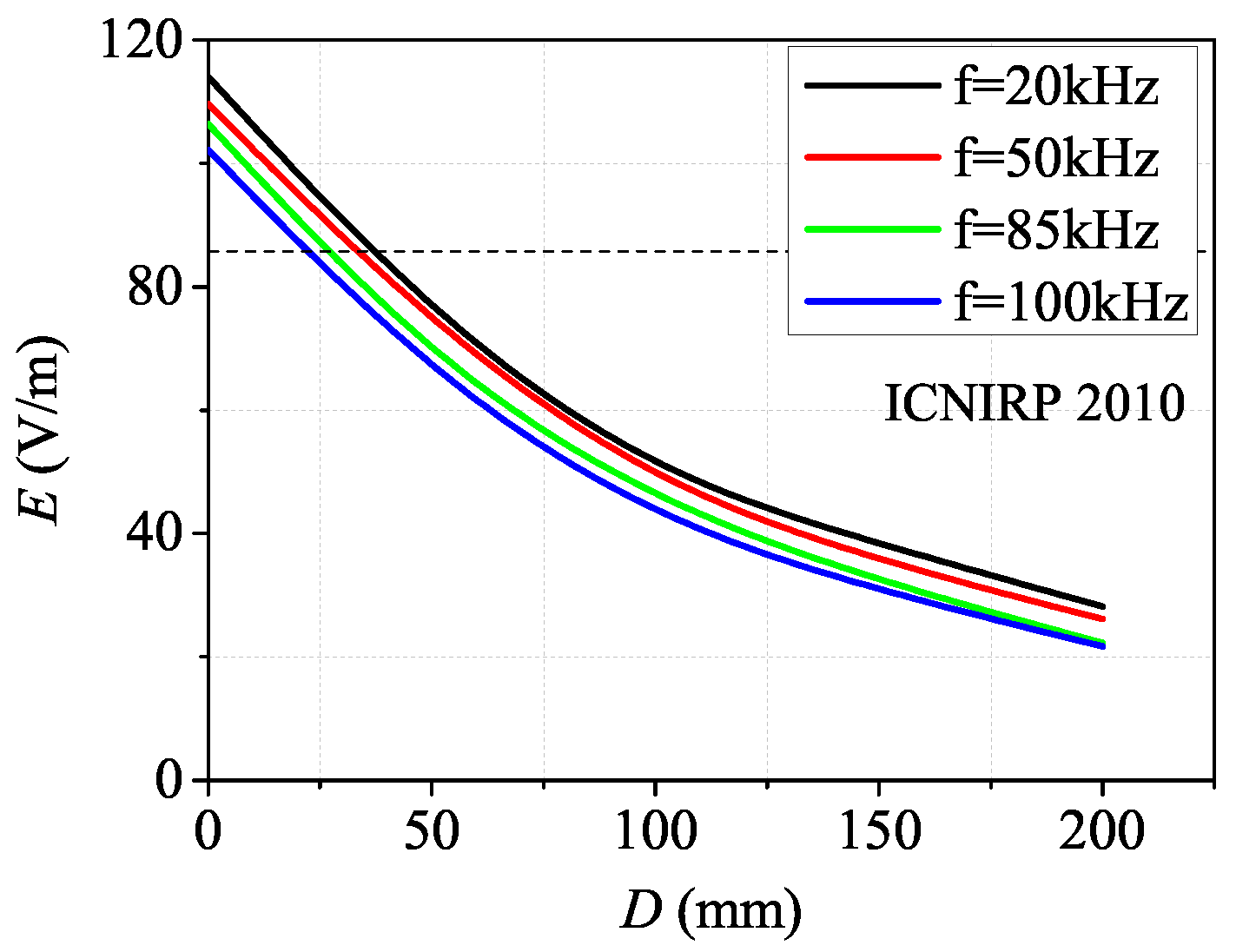
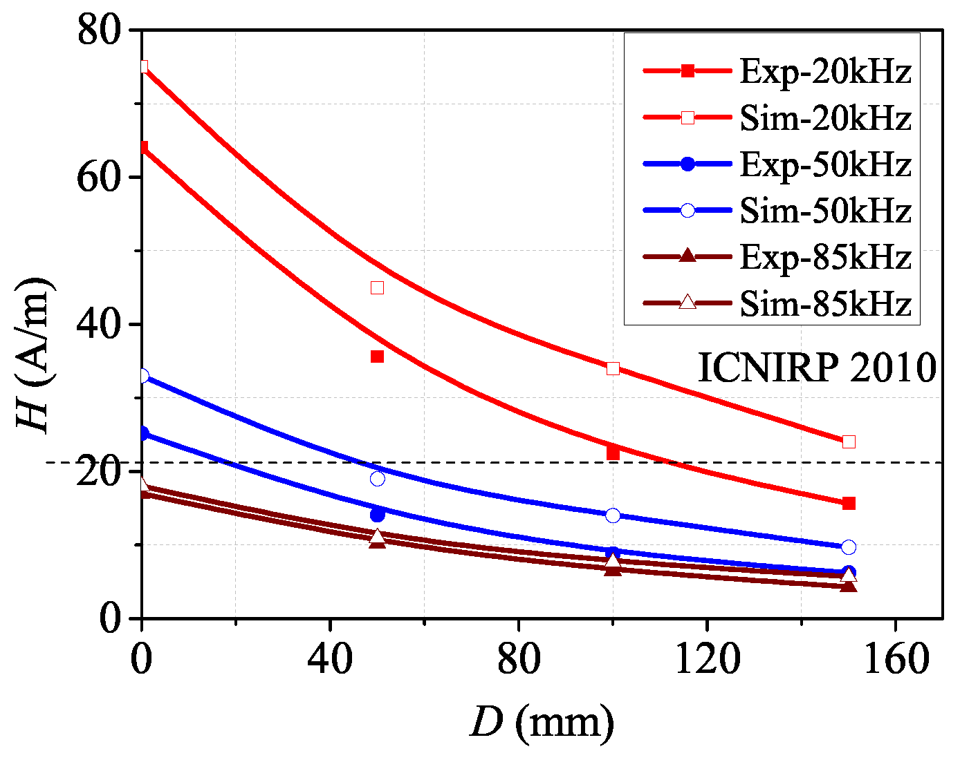
3.2. Different Frequency and Distance
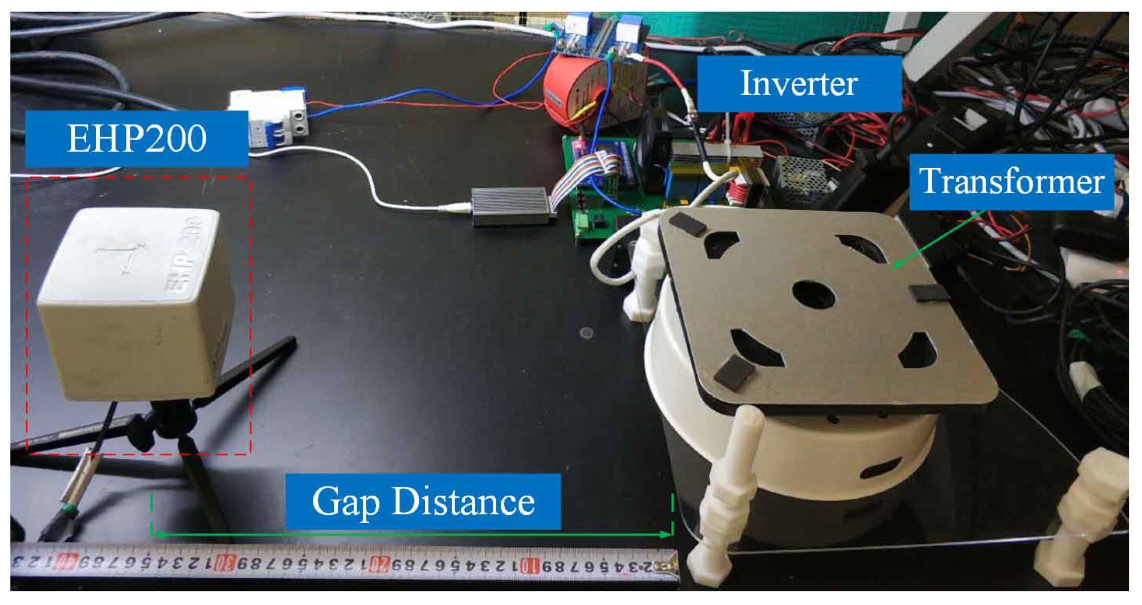
As shown in Figure 10, the MFS H decreases rapidly as the horizontal distance between the human body and the kitchen appliances increases. When operating at 85 kHz, the MFS is maintained below the ICNIRP 2010 reference limit of 21 A/m with all distances; when operating at 50 kHz, the limit requirements can be satisfied only when the distance D reaches 43 mm or more; for the 20 kHz case, the safe distance increases to 160 mm. For the EFS value, as shown in Figure 11, the pattern of the EFS changing with distance is similar to that of the MFS value. Here, the dotted lines with frequencies on the right indicate the standard value at the corresponding frequencies according to various standards. It should be noted that the EFS remains proportional to the output power despite the variation in distance. Meanwhile, the effect of the operating frequency on the EFS is quite slight compared to the MFS case in Figure 10.
Section 3.1 introduces the internal EFS E rms for the whole body and E 99th for specific organs of the human body. To make the corresponding comparison more meaningful, these two basic limit values in terms of various organs, distance to the electric device, and operating frequency will be analyzed in detail in this part. Since the induced electric fields generated by skin and superficial adipose tissue (SAT) are the most powerful compared with other organs according to the simulated results, the EFS of these two organs are taken as examples here. As shown in Figure 12, the difference between the EFS values produced by skin and SAT is large due to the variability in the permittivity and conductivity of these two organs. It can be observed that compared with the whole body of Figure 7, E rms is much closer to E 99th in the given organ. For example, when operating at 20 kHz, E rms of SAT satisfies the basic restriction when the distance between the human body and the electric device is over 50 mm. In this case, E rms can be adopted as a reference of E 99th .
Figure 13 illustrates the pattern of surface current density J rms changes with distance under various conditions. It can be observed that J rms decreases exponentially with distance. At the same distance, J rms is independent of frequency. Moreover, the basic restrictions of ICNIRP 1998 are stricter than those of ICNIRP 2010. For instance, when operating at 50 kHz, compared with the safe distance of about 40 mm of ICNIRP 2010 in Figure 11, the safe distance of ICNIRP 1998 increased to about 45 mm according to Figure 13. The simulated results agree well with the results in the previous section.

4. Validation

Based on the above analysis, a prototype of the IPT system is established according to the parameters listed in Table 3. To verify the effect of the space electric field and magnetic field on the human body, an EMF analyzer, EHP200, from Narda, Germany, is utilized in this paper, with the EFS range of 0.02 V/m–1000 V/m, MFS range of 6 mA/m–300 A/m, and measurement frequency range of 9 kHz–30 MHz. The EMF analyzer is used to test the spatial electric and MFS and to simulate the distance between the position of the human body and the IPT system, as shown in Figure 14.
During the aforementioned theoretical analysis, the EFS refers to the strength of the induced electric field within the human body. For the practical space EMF assessment, the EFS and the MFS are measured and compared with the reference limits in the ICNIRP 2010 or IEEE C95.1 2005 standards. Figure 15 shows the intensity of electric field radiation received by a simulated human body in the same plane as the transmitting coil at a distance of 140 mm, from the edge of the primary coil at various frequencies and output powers. It can be observed that in spite of the various resonant currents operating at different frequencies, according to the law of electromagnetic induction, the spatial electric field intensity generated by the system under the same power is consistent, which matches well with the theoretical results. In addition, according to the ICNIRP 2010 EFS reference level of the 83 V/m limit requirements, when the power exceeds 1750 W, the human body is subject to electric field radiation that exceeds the limit reference standard.
As shown in Figure 16, the strength of the magnetic field generated in space varies due to the various resonant currents at different frequencies. Comparing the curves in Figure 5 and Figure 16, it can be observed that the experimental and simulated results match well in the low power case. In the high power case (above 2 kW), due to the size limitation of the measurement probe, the spatial averaging of x-y-z reduces the actual measurement value. As the width of the measuring probe is 92 mm, the shell thickness of the probe is about 10mm, and the transfer distance is 350 mm, the uncertainty when detecting the center of the coil caused by the measuring probe can be calculated as approximately ± 5.1 % . In addition, when using the operating current to simulate the output voltage, it would not be accurate for a practical situation. According to the current values listed in Table 4, the current fluctuation rate can be estimated as ±0.05 A. Using the max and min current values obtained from the table, i.e., 16.1 A and 0.46 A, the uncertainty caused by the current detection can be calculated as around ±0.3∼10.8%. For the limit values of radiation exposure to the human body, both the electric and magnetic field strengths need to be considered.
Figure 17 shows the measured results of the influence of electric field radiation on the human body (simulated) at different distances when the system operates at the maximum power output. It can be obtained that when the distance exceeds 75 mm (the starting position is 140 mm, which is calibrated as the zero point), the electric field strength on the human body is below the reference limit. As shown in Figure 18, there exists a certain deviation between the measured value of the magnetic field strength on the human body and the simulated value in different positions when operating at the frequency of 20 kHz. According to the ICNIRP 2010 standard, the requirements of the reference standard are all satisfied when operating below 85 kHz. Note that there exists a certain deviation between the experimental value (20 mm) and the simulated value (44 mm) at 50 kHz. This is mainly due to the inconsistency between the measurement voxel unit of the measurement probe size and the simulation measurement unit, resulting in the difference of the rms value. Parameter correction should be performed in optimization procedures.

5. Conclusions

This paper studied in detail the key issues of the impact of an inductive power transfer (IPT) system designed for kitchen appliances on human safety. By analyzing and comparing the limit requirements of various safety standards, ICNIRP 2010 was determined as the reference safety standard. The electromagnetic field simulation model of the human body in the IPT system designed for kitchen appliances was established, and the pattern of the effect of the safety limit under the electromagnetic field environment was investigated and revealed. The relationship between the internal limit of the human body and the influence of the external output under different electromagnetic fields was analyzed. On this basis, design guidelines for wireless appliances satisfying safety standards can be obtained. A prototype was constructed to simulate the position and working conditions of the human body and the kitchen appliance. Both experimental and analytical results showed that the reference level for the safety of the human body is stricter than the basic restriction, and the electric field inside the human body is positively related to the output power. By increasing the operating frequency, the safety of the IPT kitchen appliance system can be effectively improved. Our future work will include the extension of the safety analysis and comparison to various coupling topologies.

Author Contributions

Formal analysis, J.Z.; Methodology, Y.L.; Project administration, C.Z.; Supervision, C.C.C.; Writing—original draft, Y.L. All authors have read and agreed to the published version of the manuscript.

Funding

This research was funded by National Natural Science Foundation of China grant number 52107002.

Institutional Review Board Statement

Not applicable.

Informed Consent Statement

Not applicable.

Data Availability Statement

Not applicable.

Conflicts of Interest

The authors declare no conflict of interest.

References

  1. Ma, Y.; Mao, Z.; Zhang, K. Optimization Design of Planar Circle Coil for Limited-Size Wireless Power Transfer System. Appl. Sci. 2022, 12, 2286. [Google Scholar] [CrossRef]
  2. Wang, Z.; Li, Y.; Sun, Y.; Tang, C.; Lv, X. Load Detection Model of Voltage-Fed Inductive Power Transfer System. IEEE Trans. Power Electron. 2013, 28, 5233–5243. [Google Scholar] [CrossRef]
  3. Xia, C.; Liu, L.; Liu, Y.; Ma, Z. IPT system for tail-free household appliances in the smart home system. IET Power Electron. 2019, 12, 1002–1010. [Google Scholar] [CrossRef]
  4. ICNIRP. Guidelines for limiting exposure to time-varying electric, magnetic, and electromagnetic fields (up to 300 GHz). Health Phys. 1998, 74, 494–522. [Google Scholar]
  5. ICNIRP. Guidelines for limiting exposure to time-varying electric, magnetic, and electromagnetic fields (1 Hz to 100 kHz). Health Phys. 2010, 99, 818–836. [Google Scholar] [CrossRef]
  6. IEEE Std C95.1a-2010; IEEE Standard for Safety Levels with Respect to Human Exposure to Radio Frequency Electromagnetic Fields. IEEE: Piscataway, NJ, USA, 2010; pp. 1–9.
  7. Kalialakis, C.; Georgiadis, A. The regulatory framework for wireless power transfer systems. Wirel. Power Transf. 2014, 1, 108–118. [Google Scholar] [CrossRef] [Green Version]
  8. EN IEC 62311:2020; Assessment of Electronic and Electrical Equipment Related to Human Exposure Restrictions for Electromagnetic Fields (0 Hz–300 GHz). IEC Webstsore: Geneva, Switzerland, 2020.
  9. De Santis, V.; Douglas, M.; Kuster, N.; Chen, X.L. Issues of ICNIRP guidelines when determining compliance with LF exposure limits. In Proceedings of the EMC Europe Conference, Manchester, UK, 16–21 September 2012; IEEE: Piscataway, NJ, USA, 2012; pp. 1–4. [Google Scholar]
  10. Christ, A.; Douglas, M.; Nadakuduti, J.; Kuster, N. Assessing human exposure to electromagnetic fields from wireless power transmission systems. Proc. IEEE 2013, 101, 1482–1493. [Google Scholar] [CrossRef]
  11. Shimamoto, T.; Laakso, I.; Hirata, A. In-situ electric field in human body model in different postures for wireless power transfer system in an electrical vehicle. Phys. Med. Biol. 2014, 60, 163. [Google Scholar] [CrossRef]
  12. Laakso, I.; Hirata, A. Evaluation of the induced electric field and compliance procedure for a wireless power transfer system in an electrical vehicle. Phys. Med. Biol. 2013, 58, 7583. [Google Scholar] [CrossRef] [Green Version]
  13. Zhang, Z.; Tong, R.; Liang, Z.; Liu, C.; Wang, J. Analysis and Control of Optimal Power Distribution for Multi-Objective Wireless Charging Systems. Energies 2018, 11, 1726. [Google Scholar] [CrossRef] [Green Version]
  14. Campi, T.; Cruciani, S.; Maradei, F.; Feliziani, M. Magnetic Field during Wireless Charging in an Electric Vehicle According to Standard SAE J2954. Energies 2019, 12, 1795. [Google Scholar] [CrossRef] [Green Version]
  15. Sunohara, T.; Hirata, A.; Laakso, I.; Onishi, T. Analysis of in situ electric field and specific absorption rate in human models for wireless power transfer system with induction coupling. Phys. Med. Biol. 2014, 59, 3721. [Google Scholar] [CrossRef] [PubMed]
  16. Laakso, I.; Tsuchida, S.; Hirata, A.; Kamimura, Y. Evaluation of SAR in a human body model due to wireless power transmission in the 10 MHz band. Phys. Med. Biol. 2012, 57, 4991. [Google Scholar] [CrossRef] [PubMed]
  17. Hirata, A.; Ito, F.; Laakso, I. Confirmation of quasi-static approximation in SAR evaluation for a wireless power transfer system. Phys. Med. Biol. 2013, 58, N241. [Google Scholar] [CrossRef]
  18. De Santis, V.; Giaccone, L.; Freschi, F. Influence of Posture and Coil Position on the Safety of a WPT System While Recharging a Compact EV. Energies 2021, 14, 7248. [Google Scholar] [CrossRef]
  19. Chen, X.L.; De Santis, V.; Umenei, A.E. Theoretical assessment of the maximum obtainable power in wireless power transfer constrained by human body exposure limits in a typical room scenario. Phys. Med. Biol. 2014, 59, 3453. [Google Scholar] [CrossRef]
  20. Xiao, C.; Cheng, D.; Wei, K. An LCC-C Compensated Wireless Charging System for Implantable Cardiac Pacemakers: Theory, Experiment and Safety Evaluation. IEEE Trans. Power Electron. 2017, 33, 4894–4905. [Google Scholar] [CrossRef]
  21. Ramrakhyani, A.K.; Lazzi, G. Multi-coil approach to reduce electromagnetic energy absorption for wirelessly powered implants. Healthc. Technol. Lett. 2014, 1, 21. [Google Scholar] [CrossRef] [Green Version]
  22. Koohestani, M.; Ettorre, M.; Zhadobov, M. Wireless power transfer: Are children more exposed than adults? In Proceedings of the 2017 11th European Conference on Antennas and Propagation (EUCAP), Paris, France, 19–24 March 2017.
  23. Christ, A.; Douglas, M.G.; Roman, J.M.; Cooper, E.B.; Sample, A.P.; Waters, B.H.; Smith, J.R.; Kuster, N. Evaluation of Wireless Resonant Power Transfer Systems With Human Electromagnetic Exposure Limits. IEEE Trans. Electromagn. Compat. 2013, 55, 265–274. [Google Scholar] [CrossRef]
  24. Zhang, W.; White, J.C.; Abraham, A.M.; Mi, C.C. Loosely Coupled Transformer Structure and Interoperability Study for EV Wireless Charging Systems. IEEE Trans. Power Electron. 2015, 30, 6356–6367. [Google Scholar] [CrossRef]
  25. Ding, P.P.; Bernard, L.; Pichon, L.; Razek, A. Evaluation of Electromagnetic Fields in Human Body Exposed to Wireless Inductive Charging System. IEEE Trans. Magn. 2014, 50, 1037–1040. [Google Scholar] [CrossRef]
  26. Madzharov, N.; Hinov, N. Flexibility of Wireless Power Transfer Charging Station Using Dynamic Matching and Power Supply with Energy Dosing. Appl. Sci. 2019, 9, 4767. [Google Scholar] [CrossRef] [Green Version]
Figure 1. Comparison of (a) H-field strength and (b) E-field strength of various safety standards.
Energies 15 05218 g001
Figure 2. Equivalent circuit model of an IPT system designed for kitchen appliances.
Energies 15 05218 g002
Figure 3. Diagram of relative position between human tissue and coupling coils.
Energies 15 05218 g003
Figure 4. Schematic of the magnetic coil in the presented system.
Energies 15 05218 g004
Figure 5. Curves of H-field strength at various frequencies and power levels.
Energies 15 05218 g005
Figure 6. Curves of the internal E-field strength of human body changes with output power and frequency based on the (a) ICNIRIP 2010 standard and (b) IEEE C95.1 standard.
Energies 15 05218 g006
Figure 7. Curves of the internal E-field strength of the human body versus the output power at various frequencies.
Energies 15 05218 g007
Figure 8. Curves of the surface current density of the human body versus the output power at various frequencies.
Energies 15 05218 g008
Figure 9. Curves of the (a) SAR−1g value and (b) SAR−10g value of the human body versus output power and operating frequency.
Energies 15 05218 g009
Figure 10. Curves of the H-field strength of the human body versus transfer distance at various frequencies.
Energies 15 05218 g010
Figure 11. Curves of internal E-field strength of the human body versus transfer distance at various frequencies.
Energies 15 05218 g011
Figure 12. Curves of the (a) SAR-1g value and (b) SAR-10g value of the human body versus distance and operating frequency.
Energies 15 05218 g012
Figure 13. Curves of surface current density of the human body versus distance at various frequencies.
Energies 15 05218 g013
Figure 14. Experimental prototype.
Energies 15 05218 g014
Figure 15. Measured results of E-field strength versus output power and operating frequency.
Energies 15 05218 g015
Figure 16. Measured results of H-field strength versus output power and operating frequency.
Energies 15 05218 g016
Figure 17. Measured results of E-field strength versus distance and operating frequency.
Energies 15 05218 g017
Figure 18. Measured results of H-field strength versus distance and operating frequency.
Energies 15 05218 g018
Table 1. Comparison of operating standards for various IPT applications.
ParameterImplant MedicalElectricHousehold
Devices [20,21,22,23]Vehicles [24,25,26]Applications [3]
Power≤5 W≥3.3 kW≤3.5 kW
Frequency100 kHz∼6.78 MHz85 kHz20∼100 kHz
Gap<5 mm>20 cm<15 cm
Radiating areaSame size with fitting coilFrom knee to feetFrom chest to knee
Radiating directionAxialRadialAxial & Radial
Reference standardICNIRP/IEEEICNIRPICNIRP
Reference levelsNA E & H E & H
Basic restrictionsSARNAInductive E & E 99th
& SAR
Table 2. Parameters of the human body model.
ParameterValue
Age26
Height (m)1.6
Weight (kg)54.6
SAT (kg)18.6
VAT (kg)8.3
Muscle (kg)9.0
Skin (kg)4.2
Bone (kg)7.3
Table 3. Parameters of the IPT system for kitchen appliances.
ParameterValue
Transformer size (mm)D188
Number of turns32
Single turn size (mm)D4
Type of Litz wire0.1 × 600
Core typePC95
Core size (mm)54 × 15 × 14
Transfer distance (mm)7–25
Input voltage (V)220
Input power (W)580–4070
Rated power (W)500–3500
Input current (A)2.1–14.5
Resonance current (A)2.3–16.1
Frequency (kHz)20/50/85/100
Table 4. Resonant current values at various frequency and power levels.
Output Power P (W) I P @20 kHz (A) I P @50 kHz (A) I P @85 kHz (A) I P @100 kHz (A)
5002.300.920.540.46
10004.601.841.080.92
15006.902.761.621.38
20009.243.702.171.85
300013.845.543.262.77
350016.146.463.803.23
Publisher’s Note: MDPI stays neutral with regard to jurisdictional claims in published maps and institutional affiliations.

