Article

Comprehensive Comparison of a High-Speed Permanent Magnet Synchronous Motor Considering Rotor Length–Diameter Ratio

School of Electrical and Control Engineering, Xi’an University of Science and Technology, Xi’an 710054, China
*
Author to whom correspondence should be addressed.
Energies 2022, 15(14), 5256; https://doi.org/10.3390/en15145256
Submission received: 8 June 2022 / Revised: 12 July 2022 / Accepted: 18 July 2022 / Published: 20 July 2022
(This article belongs to the Special Issue Energy, Electrical and Power Engineering 2021-2022)

Abstract

:
For high-speed permanent magnet machines (HSPMMs), many design schemes of rotor length–diameter ratios can satisfy the constraints of multiple physical fields during the motor design period. The rotor length–diameter ratio greatly impacts the comprehensive performances of multiple physical fields. However, these analyses are missing in the existing literature. Therefore, this paper focuses on the influence of the rotor length–diameter ratio on comprehensive performances. Firstly, finite element models (FEM) of multiple physical fields are built by ANSYS Workbench platform and Motor-CAD software. Then, the comprehensive performances of multiple physical fields are comparatively analyzed. Finally, the designed HSPMM is implemented, based on one prototype of 60 kW, 30,000 rpm to verify the results of comparative analysis. Based on the comparative analysis above, the influent laws of rotor length–diameter ratios on comprehensive performances of multiple physical fields are discussed and summarized, which can be used as a reference for the rotor structural design of HSPMMs.

Graphical Abstract

1. Introduction

In recent years, with the development of electronic devices, high-speed permanent magnet machines (HSPMMs) access industry and life more and more widely, because of their excellent electromagnetic performance and simple control characteristics [1,2,3]. However, when the HSPMMs rotate at high speed, various problems occur, which hinder the development of HSPMMs, and solving these problems has become a research focus and hot spot for researchers [4,5,6]. In the design of HSPMMs, the key structural parameters and performances must meet the constraints of multiple physical fields, which include electromagnetic, mechanical, and thermal physical fields [7,8]. However, many rotor shapes can satisfy the constraints of multiple physical fields, from short and thick to long and thin with rotor shape, which leads to the uncertain selection of the rotor shape in the design period. Therefore, the influence of the rotor length–diameter ratio on the comprehensive performances is worthy of discussion and research. In this paper, the influence of rotor length–diameter ratio on comprehensive performances is studied and discussed, in order to obtain better comprehensive performances for HSPMMs.
In the existing literatures, the comprehensive performances of HSPMMs are comparatively investigated through key performance parameters. For electromagnetic and loss properties, some key electromagnetic parameters are comparatively analyzed, such as line back-EMF at no load, radial air-gap flux density distribution, stator iron-core loss, permanent magnet loss, air-friction loss, etc. [9,10]. For rotor stress characteristics, the rotor stresses are calculated, including radial and tangential stresses of permanent magnets, and von-Mises stress distributions of sleeve [11]. For rotor dynamics, the rotor mode and critical speed are simulated [12]. For the thermal behavior, the cooling system and temperature distribution are investigated according to the designed parameters and calculated loss characteristics [13]. It can be seen that the design of HSPMMs must meet the needs of comprehensive performances of multiple physical fields. For HSPMMs, many rotor shapes can satisfy all the needs of comprehensive performances, but different rotor length–diameter ratios have great influence on the comprehensive performances of multiple physical fields. A shorter and thicker rotor shape can effectively reduce the motor temperature rises and improve the rotor dynamics’ reliability, but the permanent magnet stress and the sleeve stress are increased due to the poor centrifugal force of the larger rotor diameter [14,15]. A longer and slender rotor shape can effectively improve the rotor stress, while the rotor dynamics and thermal characteristics may not be satisfied due to the longer rotor core length or the smaller rotor diameter [16]. It is clear from the above description that the rotor length–diameter ratio can affect motor performances, including electromagnetic, mechanical, and thermal characteristics. Hence, the influence of rotor length–diameter ratio on comprehensive performances cannot be ignored. In the existing literatures, the influence of rotor length–diameter ratio on motor performance mainly focuses on the analysis of single physical fields and the influence of the rotor length–diameter ratio on the comprehensive performance of multiple physical fields is not clear. To obtain an accurate relationship between the rotor length–diameter ratio and comprehensive performances, comparative analysis of multiple physical fields (such as electromagnetic, mechanical, and thermal) is necessary. The rotor length–diameter ratio should be investigated based on a comparative analysis of comprehensive performances, which include electromagnetic and loss characteristics, mechanical strength, rotor dynamics, and thermal performance.
Based on the above analysis, the rotor length–diameter ratio has a great influence on the comprehensive performances of multiple physical fields. However, the effect has rarely been focused on in the existing literature, which leads to the uncertain selection of the rotor length–diameter ratio in the design period of high-speed permanent magnet motors. Therefore, in this paper, the influence of the rotor length–diameter ratio on comprehensive performances is discussed and comparatively investigated. Firstly, finite element models of multiple physical fields are built. Then the influent laws of rotor length–diameter ratio on comprehensive performances are summarized. Finally, a prototype is manufactured and the comprehensive performances are experimentally measured. The conclusions obtained can be used as a reference for the rotor structural design of HSPMMs. The initial electromagnetic design scheme is introduced in Section 2. In Section 3, the process of comparative analysis is determined and three cases with representative rotor length–diameter ratios are selected. In Section 4, the comprehensive performances of these three cases are comparatively analyzed in detail. In Section 5, the designed HSPMM are manufactured and experiments are conducted. Finally, the conclusions summarized are drawn in Section 6, and some key simulation results and the influence of the rotor length–diameter ratio on comprehensive performances are summarized, which can be used as a reference for rotor structural design of HSPMMs.

2. HSPMM Structure and Main Performance

In the design of a high-speed permanent magnet motor, electromagnetic performance, losses, temperature distribution, rotor stress, and rotor dynamics should be considered comprehensively. It is necessary to analyze the comprehensive characteristics of the motor, and then the designed motor scheme can meet all needs. In the design process, it is important to determine the mechanical structure of the motor firstly, because the different mechanical structures will directly affect other performance of the designed motor [17].
In this paper, a high-speed permanent magnet machine for 60 kW at 30,000 rpm is designed and the main parameters of the motor can be obtained, as shown in Table 1. A surface-mounted permanent magnet rotor is designed. To ensure the reliability of rotor permanent magnets (PMs) rotating at high speed, a carbon fiber sleeve of 5 mm is used to improve the rotor stress, and the tensile strength of carbon fiber materials is 1400 MPa. The stator core is composed of 0.35 mm cold-rolled silicon of low-loss steel.

3. Initial Comprehensive Characteristics Comparative Analysis for HSPMM

3.1. Comprehensive Comparative Analysis Process for HSPMM

To analyze the influence of main structural parameters on the comprehensive characteristics, a process is presented, as shown in Figure 1.
Step 1: According to the basic performance parameters and rotor diameter constraints, the initial structural dimensions are determined. Step 2: The electromagnetic characteristics of different air-gap lengths are compared and analyzed, and the air-gap length is determined. Step 3: The influence of slots/poles combination on the electromagnetic characteristics is analyzed. Step 4: The number of poles is determined through the influence of the variable number of poles on electromagnetic performance. Step 5: Three cases satisfying electromagnetic design are selected, mainly considering the difference in rotor shapes. Step 6: The electromagnetic and loss characteristics are comparatively analyzed under three cases. Step 7: The rotor stresses are comparatively analyzed under three cases. Step 8: The rotor dynamics are comparatively analyzed under three cases. Step 9: The temperature distribution is comparatively analyzed under three cases.

3.2. Multiple Physic Fields Constraints

The rotor dimensions of HSPMMs are limited by the electromagnetic, mechanical, and temperature characteristics. For the electromagnetic performance, the rotor dimensions must satisfy the electromagnetic load. For the mechanism, the rotor length–diameter ratio must be within a specific range, so that the rotor will not be damaged by centrifugal force and resonance. For temperature rises, the heat dissipation design of the motor should take into account the selected cooling system and working mode, so that the temperature distribution of the motor is within the constraints. Three aspects restrict each other and determine the rotor dimensions of HSPMMs. In this paper, the following basic constraints are determined according to the actual requirements.
1.
Geometric constraints: interference fit δ s = 0.15   mm , the thickness of the sleeve h s l e e v e = 5   mm , the thickness of the magnets 7   mm h P M 8.5   mm , and the stator outer diameter D i s = 157   mm .
2.
Electromagnetic constraints: the amplitude of the line to line Back-EMF at no-load is between 500 V and 540 V, and the air-gap magnetic flux density is between 0.4 T and 0.6 T. The output power in the rated load is P o u t 60   kW , the thermal load required A J 200   A 2 / mm 3 (determined by experience).
3.
Strength constraints: the tensile strength of permanent magnet should be less than 80 MPa, and the tensile strength of carbon fiber sleeve should be less than 1400 MPa. Safety margins should be considered in the engineering, so the tensile strength limitation of the permanent magnet at rated speed is 64 MPa, and the tensile strength limitation of the sleeve at rated speed is 1100 MPa.
4.
Critical speed constraints: the rated speed of the rotor is required to be less than 0.7 times the first-order critical speed.
5.
Thermal constraints: the limited maximum working temperature of the HSPMM is 130 °C, and stator housing water cooling system is adopted.

3.3. Influence Analysis of Main Parameters on Electromagnetic Performance

3.3.1. Air-Gap Length

For different air-gap lengths, the electromagnetic performance of the motor is analyzed, such as the air-gap lengths of 0.5, 1.5, 2.0, and 3.0 mm. In this analysis, rated output power is maintained, and the thickness of the permanent magnet is increased with the increase of air-gap length. The permanent magnet thickness and electromagnetic characteristics are shown in Table 2.
The radial air-gap flux density distribution with the mechanical angle under no load and rated load is shown in Figure 2. The amplitude of the radial air-gap flux density is mainly affected by the air-gap length, and the impact of the air-gap length on harmonic order and the distribution of the radial air-gap flux density of the motor is little.
The rotor eddy-current losses under no load and rated load with different air-gap lengths are shown in Figure 3. It can be shown that the air-gap length is smaller and the rotor eddy-current loss is larger because a smaller air-gap length will cause more current harmonics to enter the rotor, resulting in more rotor eddy-current losses. As the air-gap length increases, more current harmonics will be shielded, so the rotor eddy-current losses gradually decrease. When using a smaller air-gap length, the dosage of magnets is smaller, while the rotor eddy-current loss is larger. When using a larger air-gap length, the dosage of magnets is larger, and the rotor eddy-current loss is smaller.
Therefore, the air-gap length is a compromise between rotor eddy-current losses and electromagnetic performance. Although the rotor eddy-current loss is smallest under the 3.0 mm air-gap length, electromagnetic performance cannot be guaranteed, especially for the no-load back-EMF. The rotor eddy-current losses of the 0.5 mm and 1.5 mm air-gap lengths are larger, which ultimately lead to a higher motor temperature rise. According to the level of influence of the air-gap length on rotor eddy-current loss in Figure 4, rotor eddy-current loss decreases gradually with the increase of air-gap length. Electromagnetic performance and the rotor eddy-current loss are comprehensively considered and the air-gap length of 2 mm is selected as a compromise solution.

3.3.2. Slots/Poles Combination

The slots/poles combination will affect the winding factor and the cogging torque period. Therefore, the impact of slots/poles combination on electromagnetic characteristics is not ignored.
The winding factor, cogging torque period, and load power frequency with different pole numbers are discussed in Table 3. Because of the same minimum common multiple of the poles and slots, the cogging torque period is the same. However, the stator winding factors of two-pole and four-pole motors are 0.949, and 0.933, respectively, indicating the high stator windings utilization ratios of two-pole and four-pole motors. When the power frequency is high, it will greatly increase the stator iron-core loss and rotor eddy-current loss. Therefore, in the HSPMMs, a large power-supply frequency should not be used. In conclusion, this paper adopts 24 slots and two poles or four poles in the designed motor.

3.3.3. Number of Poles

The number of poles plays a major role in HSPMMs performance. Electromagnetic characteristics of two-pole and four-pole motors under no load and rated load are analyzed. In Figure 5, for the two-pole motor, the magnetic flux density of stator yoke is greater than 1.8 T, which makes the stator yoke saturated under the same stator outer diameter of 157 mm. Therefore, the stator outer diameter of the two-pole motor should be expanded.
The stator outer diameter of the two-pole motor must be expanded to the stator yoke non-saturation. The main structural parameters of the two-pole motor and the four-pole motor are compared, as shown in Table 4. The stator outer diameter of the two-pole motor is extended by 15% over the four-pole motor, ensuring basic electromagnetic characteristics.
Electromagnetic characteristics of two-pole and four-pole motors are shown in Table 5. Although the four-pole motor has almost double stator iron-core loss density compared to the two-pole motor, the stator iron-core loss of the four-pole motor has almost 3/2 times that of the two-pole motor, as they have different iron volumes.
The two-pole and four-pole motor are compared and analyzed from the stator yoke magnetic flux density distribution, rotor eddy current, winding end length, radial air-gap flux density distribution, and line-to-line back-EMF.
In Figure 6, the maximum values of flux densities are basically the same for the two-pole and the four-pole motors, which are about 1.38 T in the stator yoke. However, the stator outer diameter is 157 mm for the four-pole motor and 181 mm for the two-pole motor, thus the utilization of the stator-yoke material is higher for the four-pole motor. The four-pole motor allows the smaller dimensions and an improved material utilization ratio.
Rotor eddy-current loss in permanent magnets is part of the cause of motor temperature rise. Rotor eddy-current density distribution on permanent magnets of the two-pole and the four-pole motors is shown in Figure 7. Obviously, the rotor eddy current of the two-pole motor is much higher than that of the four-pole motor. According to the 2D-FEA calculation, the rotor eddy-current loss of the four-pole motor is 31.52 W, which is lower than the 235.56 W of the two-pole rotor. The four-pole motor is formed by an arrangement of four magnets, and the two-pole motor consists of two magnets.
The winding end length of the two-pole motor is longer than that of the four-pole motor, because the stator winding coils of the two-pole motor have a larger pitch than that of the four-pole motor. The stator weights and coils’ half-turn lengths of two-pole and four-pole motors are compared in Table 6. According to the comparison in Table 6, the coils’ half-turn length of the four-pole motor is much shorter than that of the two-pole motor, and the weight and material consumption are much smaller than that of the two-pole motor. The radial air-gap flux density distribution with the mechanical angle and Fourier transforms results for the two-pole and the four-pole motors are shown in Figure 8 and Figure 9.
The fundamental amplitude of radial air-gap flux density of thefour4-pole motor is better, and the odd harmonic amplitude is lower than that of the two-pole motor. The amplitudes of the 11th and 13th harmonics of the four-pole motor are larger than that of the two-pole motor, because the two-pole motor adopts a shorter pitch winding, which weakens the 11th and 13th harmonics.
At rated load, the radial air-gap flux density distribution of two-pole and four-pole motor is almost the same at no load. However, at rated load, the fundamental amplitude of radial air-gap flux density of the four-pole motor is much greater than that of the two-pole motor, which can provide a higher air-gap flux density to ensure the motor generates sufficient electromagnetic torque.
The line-to-line back-EMF and the Fourier transforms results of two-pole and four-pole motors at no-load are shown in Figure 10. It can be found that the line-to-line back-EMF waveform of the two-pole motor is the flat-top wave, because the fifth and seventh harmonics amplitudes of the line-to-line back-EMF of the two-pole motor is higher, and the fundamental amplitude of the two-pole motor is slightly greater than that of the four-pole motor.
Based on the above analysis, for electromagnetic performance between two-pole and four-pole motors, the following results can be obtained.
  • For a two-pole motor, due to the stator core’s magnetic saturation, the motor dimension, coils length, and the total weight are larger than those for a four-pole motor. It is reasonable to consider a four-pole motor for the strict requirements on motor size applications.
  • For the stator-core loss, a four-pole motor is larger than that of a two-pole motor, and the main reason is the lower load frequency for the four-pole motor.
  • For the rotor eddy-current density, rotor eddy-current loss of the four-pole motor is 31.52 W, which is much lower than the 235.56 W of the two-pole rotor.
  • For the radial air-gap flux density, the fundamental amplitude of a two-pole motor is lower than that of a four-pole motor, and the high-order harmonic amplitudes of a two-pole motor are greater than that of a four-pole motor.
  • For the line-to-line back-EMF, the waveform of a four-pole motor is more sinusoidal. The fifth and seventh harmonic amplitudes of the line-to-line back-EMF of a two-pole motor are much larger than those of a four-pole motor.

3.3.4. Permanent Magnetic Materials

At present, permanent magnetic materials of HSPMMs are SmCo permanent magnet and NdFeB permanent magnet. Permanent magnetic materials usually have low mechanical strength and high thermal sensitivity. The permanent magnetic material SmCo has better temperature stability, while NdFeB has the low bending strength, low tensile strength, and compressive strength. Compared to SmCo permanent magnet, the permanent magnetic material NdFeB has poorer temperature stability, but the better magnetic property, better mechanical properties, and the lower price. The performances of the two permanent magnetic materials are shown in Table 7. To ensure the mechanical strength of the rotor, permanent magnet NdFeB is used.

3.4. Comprehensive Comparative Analysis Schemes for Rotor Shape

For the requirements of electromagnetic performance, some designers design the rotor short and thick, and some designers design the rotor long and thin. The length–diameter ratio of the rotor is defined as λ = L e f / D r .
There are few studies in the literature on the influence of the length–diameter ratio on the multiple physical characteristics of the motor. In this paper, under the constraints of the multiple characteristics, three design cases are selected for comprehensive comparative analysis. Case 1 has the rotor shape of short and thick, and the length–diameter ratio is smallest. Case 3 has the rotor shape of long and thin, and the length–diameter ratio is biggest. Case 2 is an intermediate state between the rotor shapes of Case 1 and Case 3. The structural parameters of the rotor shape for the three cases are shown in Table 8.

4. Comprehensive Comparison for Rotor Shape

4.1. Electromagnetic and Losses Characteristics Analysis

The two-dimensional finite element model (2D-FEM) is established for the HSPMM with three rotor shapes. The magnetic flux density distribution and flux line distribution are calculated for the rated load condition, as shown in Figure 11. In Case 1, the magnetic flux density is the highest, which is about 1.72 T. The magnetic flux density of the motor in Case 2 is the lowest, which is about 1.38 T. For Case 3, the magnetic flux density is about 1.506 T. If the magnetic flux density is too high, the iron core would be saturated, and the iron-core loss and temperature rise increased.
The line-to-line back-EMF and its Fourier transform results in three cases under no-load conditions are shown in Figure 12. In Case 1, the fundamental amplitude is slightly lower, and the 5th and 11th harmonics are slightly higher. Case 2 and Case 3 are the same.
The radial air-gap flux density with mechanical angle waveform and Fourier transforms results are compared and analyzed for the three cases under the no load and rated load, as shown in Figure 13. The fundamental amplitude of Case 1 is the biggest, while the corresponding high-order harmonics amplitude is also highest. The fundamental amplitude of Case 2 is lower than Case 1, while the amplitude of the high-order harmonics is also smaller than Case 1. In Case 3, the fundamental amplitude is about 0.46 T, which is smallest and is not conducive to the electromagnetic performance of the motor.

4.2. Losses Comparative Analysis

4.2.1. Rotor Eddy-Current Loss Comparative Analysis

The rotor eddy-current density in the three rotor shapes at rated load is shown in Figure 14. It can be found that the rotor eddy-current density on the permanent magnets in Case 3 is the smallest, and the rotor eddy-current density on the permanent magnets in Case 1 is the largest. Rotor eddy-current losses of the permanent magnets are calculated, as shown in Figure 15. The rotor eddy-current loss in Case 1 is the highest, which is about 121.4 W, indicating that the rotor temperature rises in Case 1 would be serious. Case 3 has smallest rotor eddy-current loss, which is about 5.7 W. Obviously, as the rotor length–diameter ratio grows, the rotor eddy-current loss decreases.

4.2.2. Stator Iron-Core Loss Comparative Analysis

The stator iron-core losses calculation results under the three cases are shown in Figure 16. According to Berttoti’s discrete model of iron-core losses, the iron-core losses are related to the amplitude and frequency of magnetic flux density in the stator core. From the magnetic flux density distribution in Figure 11, the magnetic flux density amplitude of the stator yoke in Case 3 is the highest, so the iron-core loss is the largest.

4.2.3. Air-Friction Losses Comparative Analysis

The rotor surface linear velocity of HSPMMs is higher, air-friction loss is larger than that of the low-speed motor. Air-friction loss of HSPMMs has a large influence on the design of the rotor shape structure and motor temperature rise. Air-friction loss calculation values of the three cases are shown in Figure 17. It can be found that the bigger the rotor diameter, the larger the air-friction loss at rated speed.

4.3. Rotor Stress Characteristics Analysis

4.3.1. Rotor Stress Comparative Analysis at a Cold State

In this paper, 3D-FEM are established for the stress of permanent magnets and sleeve under three cases. The radial and tangential stress of permanent magnets and the Von-Mises stress of the sleeve at a cold state are obtained. Figure 18 shows the Von-Mises stress distribution diagram of the sleeve. It can be found that the Von-Mises stress of the sleeve decreases with the decrease in the rotor diameter at a cold state, and the results are consistent with the theoretical analysis.
Figure 19 indicates the tangential stress distribution of permanent magnets. It can be found that the tangential stress of permanent magnets in Case 1 is the highest at 40.246 MPa in a cold state. The tangential stress of permanent magnets in Case 3 is the lowest at 8.74 MPa in a cold state. The tangential stress of permanent magnets is mainly related to the interference fit. When the interference fit increases, the assembly of permanent magnets becomes closer, and its tangential stress decreases correspondingly. However, excessive interference fit would increase the radial pressure of permanent magnets and increase the technology assembly and manufacturing difficulty.
The radial stress diagram of the permanent magnets under the three cases is shown in Figure 20. The radial stress of permanent magnets indicates the centrifugal force of the permanent magnets when the rotor is rotating at the rated speed. It can be found that the stress at the periphery of the permanent magnets is minimal, due to the radial pressure exerted by the sleeve on the permanent magnets and the centrifugal force of the rotor canceling each other out.

4.3.2. Rotor Stress Comparative Analysis at a Hot State

For the three cases, the Von-Mises stresses of sleeve, tangential stress, and radial stress of permanent magnets are comparatively analyzed at a hot state. The Von-Mises stress distribution of the sleeve is shown in Figure 21, the tangential stress distribution of permanent magnets is shown in Figure 22, and the radial stress distribution of permanent magnets is shown in Figure 23. At the hot state, it can be found that the radial and tangential stress of magnets increase with the temperature rise, while the carbon fiber sleeve Von-Mises stress did not change, indicating that the thermal stability of the permanent magnets is poorer, and the performance of the permanent magnets is strongly influenced by temperature rise. According to the stress calculation results at a hot state, the tangential stress of permanent magnets under Case 1 is 87.5 MPa, which has exceeded the thermal constraints. Therefore, the rotor shape of Case 1 cannot meet the constraints of rotor stress.
From the above rotor stresses analysis under the cold and hot state, it can be found that as the rotor length-diameter ratio increases, the rotor outer diameter gradually decreases, thus the rotor stress gradually decreases, indicating that the mechanical reliability of the rotor gradually increases.

4.4. Rotor Dynamics Characteristics Analysis

When the high rotor speed of HSPMMs reaches its critical speed, the rotor would resonate and damage the rotor. To avoid resonance, the rated speed of the rotor should be less than 0.7 times the first-order critical speed.
The first-order critical speed of the rotor is related to the diameter and length of the rotor. For case 1, D r / L e f 2 = 2.5 × 10 2 , for case 2, D r / L e f 2 = 5.12 , and for case 3, D r / L e f 2 = 1.2 × 10 3 .
The supporting stiffness of the rotor is set as 3.5 × 10 4   N / mm . Modes of oscillation are obtained by the 3D-FEM calculation. Figure 24 shows the first order and second order modes of the rotor for Case 1, Case 2, and Case 3. It is found that the first critical speed of the rotor is 43,800 rpm for Case 1, 168,220 rpm for Case 2, and 44,663 rpm for Case 3, which indicates that the rotor dynamics meet the stability requirements for the three cases, and smaller and larger length–diameter ratios may cause the rotor to resonate more easily.

4.5. Thermal Characteristics Analysis for Three Cases

In this paper, the housing water cooling system is used for heat dissipation design. The cooling system must ensure the safe operation and lifetime of the designed motor. The maximum tolerable temperature of the permanent magnets is limited to less than 130 °C to increase the reliability. Furthermore, the maximum winding temperature is set to 130 °C to increase the service life of the HSPMM.
To meet the temperature constraints, a housing water cooling system is designed for the motor. The water duct cools the motor through the spiral waterway on the stator housing. The distribution of spiral ducts is shown in Figure 25. In this design, the cooling water temperature and the ambient temperature are both 30 °C, and the water flow rate is set to 2 m3/h.
The temperature distribution and comparison of the stator windings, stator cores, and permanent magnets are shown in Figure 26 and Figure 27. For the three cases, the maximum temperatures of the winding and rotor are lower than the limiting temperature values. However, the temperature of permanent magnets of Case 1 is slightly lower than that in the other two cases. When the motor temperature requirements are extremely strict and the cooling system is also limited, the smaller rotor length–diameter ratio design can reduce the permanent magnet temperature slightly. In Figure 27, it can be found that as the rotor length–diameter ratio increases, the temperature of stator reduces gradually, and the temperature of rotor increases.

5. Prototype and Experimental Tests

Based on the above analysis, Case 2 can satisfy the comprehensive performance constraints best, so Case 2 is selected as the final design parameters of the 60 kW at 30,000 rpm HSPMM. Then, a prototype is manufactured, as shown in Figure 28. Electromagnetic and thermal tests are also measured, including the power, back-EMF, and winding temperature, as shown in Table 9.
The line-to-line back-EMF of no-load operation is measured with the prototype driven by another motor. The measured peak-to-peak value of line-to-line back-EMF at 30,000 rpm is 520 V, which is nearly the same as the designed voltage. The stator windings temperature at rated load is measured by the Pt100 resistance temperature detectors installed in the stator slots. It can be found that the temperature of the measured windings is 60.9 °C, which is close to the FEM calculation results of 56.7 °C. Obviously, for the designed HSPMM, the measured value of electromagnetic performance and temperature characteristics are close to the calculated results, to satisfy the electromagnetic and thermal constraints.
In addition, the prototype is shown to work at the rated speed for a long period. There is no damage to the rotor, which indicates that the design of the HSPMM is also reasonable and that the designed motor satisfied all the comprehensive performance constraints in the actual industry.
Overall, the experimental prototype tests show that the designed motor meets all physical field constraints, including electromagnetic, mechanical, and thermal characteristics, and as this paper proposed, the influent law of rotor length–diameter ratio on comprehensive characteristics is beneficial for the HSPMMs.

6. Conclusions

For the high-speed permanent magnet machines design, many rotor shape schemes can satisfy the multiple physical fields’ comprehensive performances. A variety of rotor length–diameter ratios are available, from stubby to slender. However, different rotor length–diameter ratios impact on multiple physical fields’ performances. The effect of rotor length–diameter ratio on multiple physical fields’ comprehensive performances have rarely been focused on in the existing literature, which leads to an uncertain selection of the rotor length–diameter ratio in the design period of high-speed permanent magnet motors.
In this paper, finite element models of electromagnetic properties, rotor stresses, rotor dynamics, and temperature are built by the corresponding finite element analysis software, and the multiple physical fields performances are analyzed numerically and comprehensively comparatively analyzed through the finite element models.
The following key simulation results can be drawn from a comprehensive comparative analysis.
  • When keeping the same stator outer diameters for the two-pole motor and four-pole motor, the stator yoke of the two-pole motor is magnetically saturated. The stator outer diameter of the two-pole motor is enlarged by 15% to avoid the magnetic flux density of stator-core saturation. The stator coils half-turn length of the four-pole motor is 197.258 mm, which is much shorter than the 299.492 mm of the two-pole motor. Rotor eddy-current loss of the four-pole motor is 31.52 W, which is much lower than the 235.56 W of the two-pole rotor. Compared to the two-pole motor, the four-pole motor has the higher power density.
  • With the smallest rotor length–diameter ratio, Case 1 has the largest rotor eddy-current loss (121.4 W), lowest core loss (720.8 W), and largest air-friction loss (115.7 W). With the largest rotor length–diameter ratio, Case 3 has the smallest rotor eddy-current loss (5.7 W), highest core loss (923.3 W), and smallest air-friction loss (78.0 W).
  • For the three design cases, Case 1 has the smallest rotor length–diameter ratio and the largest rotor outer diameter, and thus the sleeve stress and permanent magnet tangential and radial stresses are both the largest regardless of operating in cold and hot states, which are 259 MPa, 7.71 MPa, and 33.051 MPa for the cold state, and 384 MPa, 37.1 MPa, and 48.02 MPa for the hot state. Case 3 has the largest rotor length–diameter ratio and the smallest rotor outer diameter, and thus has the smallest sleeve stress and permanent magnet tangential and radial stresses in both the cold state and the hot state, which are 185.95 MPa, 1.64 MPa, and 14.881 MPa for the cold state, and 216.32 MPa, 3.98 MPa, and 31.745 MPa for the hot state.
  • The influence of the rotor length–diameter ratio on rotor dynamics performance is compared and investigated. The first critical speed of the rotor is 43,800 rpm for Case 1, 68,220 rpm for Case 2, and 44,663 rpm for Case 3.
  • The temperatures of the stator windings for the three cases are 86.3 °C, 56.7 °C, and 50.8 °C, respectively. The temperatures of permanent magnets for the three cases are 84.2 °C, 116.3 °C, and 126.3 °C, respectively.
In this paper, the analysis results show different rotor length–diameter ratios greatly influence multiple physical fields’ comprehensive performances, and these influent laws are crucial to the design of high-speed permanent magnet motors. Thus, in the design period of high-speed permanent magnet machines, the influence of rotor length–diameter ratio on multiple physical fields’ comprehensive performances should be considered and investigated, in order to obtain better multiple physical fields’ comprehensive performances.
In order to verify the theoretical analysis, based on the comprehensive characteristics comparative analysis results, one 60 kW at 30,000 rpm HSPMM is designed. Multiple physical fields’ comprehensive comparative analysis results are tested through prototype experiments. The RMS value of the no-load line back-EMF during rated operation is 520 V, which is very close to the calculated result 523 V and the stator winding stabilized temperature is 60.9 °C, which agrees with the analysis result 56.7 °C. The analytical method is confirmed by the experimental results of the prototype.
In the existing literature, for high-speed permanent magnet motor design, the influence of rotor length–diameter ratios on multiple comprehensive physical performances is not usually considered, so the rotor shape can be designed in various forms, such as a short and thick rotor or long and thin rotor. However, different comprehensive physical properties are produced by different rotor shapes, which are very important for the design of high-speed motors. In this paper, the influence of rotor length–diameter ratio on the comprehensive performance of multiple physical fields is considered and investigated, which includes electromagnetic characteristics, losses properties, rotor stresses distributions, rotor dynamics, and thermal behavior. Through comprehensive comparative analysis of different rotor length–diameter ratios, the following conclusions can be obtained, which have not been proposed in the previous literatures.
  • For the electromagnetic characteristics, as the rotor length–diameter ratio goes up, the fundamental amplitude of the no-load line back-EMF increases gradually and the fundamental and high-order harmonical amplitudes of the no-load and rated-load radial air-gap flux density decreases.
  • For the loss properties, as the rotor length–diameter ratio grows, the rotor eddy-current loss decreases, the stator-core loss increases, and the air-friction loss decreases.
  • For the rotor stresses’ distributions, as the rotor length–diameter ratio increases, the rotor outer diameter gradually decreases, thus the rotor stress gradually decreases, indicating that the mechanical reliability of the rotor gradually increases.
  • For the rotor dynamics, smaller and larger length–diameter ratios may cause the rotor to resonate more easily.
  • For the thermal behavior, as the rotor length–diameter ratio increases, the temperature of stator reduces gradually, and the temperature of rotor increases.
Based on the analysis above, it can be concluded that the influence of the rotor length–diameter ratio on multiple comprehensive physical performances cannot be ignored and different rotor length–diameter ratios greatly impact on the multiple comprehensive physical performances of HSPMMs. The conclusions obtained in this paper can be used as a reference for rotor structural design of HSPMMs.
In this paper, the destructive experiments usually performed to test rotor stresses could not be directly tested on to the rotor at high-speed rotation, due to the limitation of the test equipment. Thus, the reliability of the rotor is indirectly verified through the long-term operation of the HSPMMs.
In the future, to provide more valuable conclusions, the rotor length–diameter ratio should be further optimized by adopting an optimization analysis method, based on a coupled multi-physics performance, which could achieve a better multi-physics performance of the HSPMMs.

Author Contributions

Conceptualization, G.D. and Y.Z.; data curation, W.G. and G.D.; formal analysis, W.G.; funding acquisition, G.D.; investigation, W.G. and G.D.; methodology, W.G. and G.D.; project administration, G.D.; resources, G.D.; software, W.G.; supervision, Y.Z.; validation, G.D., Y.Z., T.P. and N.L.; visualization, W.G.; writing–original draft, W.G.; writing–review and editing, W.G., G.D., T.P. and N.L. All authors have read and agreed to the published version of the manuscript.
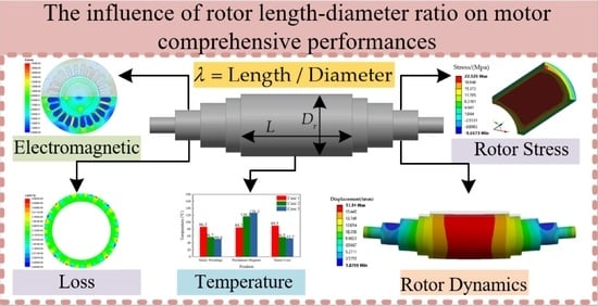
Funding

This research was funded by National Nature Science Foundation of China, grant number 52177056.

Institutional Review Board Statement

Not applicable.

Informed Consent Statement

Not applicable.

Data Availability Statement

Not applicable.

Conflicts of Interest

The authors declare no conflict of interest.

Nomenclature

δ s Interference fit.
h s l e e v e The thickness of the sleeve.
h P M The thickness of the permanent magnet.
D i s Stator outer diameter.
P o u t Output power at the rated load.
A J Thermal load.
δ Air-gap length.
B Magnetic flux density.
J Current density.
λ Rotor length–diameter ratio.
L e f Effective core length.
D r Rotor outer diameter.

References

  1. Du, G.H.; Zhou, Q.X.; Liu, S.L.; Huang, N.; Chen, X. Multiphysics design and multiobjective optimization for high-speed permanent magnet machines. IEEE Trans. Transp. Electrif. 2020, 6, 1084–1092. [Google Scholar] [CrossRef]
  2. Du, G.H.; Xu, W.; Zhu, J.G.; Huang, N. Power loss and thermal analysis for high-power high-speed permanent magnet machines. IEEE Trans. Ind. Electron. 2020, 67, 2722–2733. [Google Scholar] [CrossRef]
  3. Du, G.H.; Huang, N. Multiphysics analysis of high-speed permanent magnet generators for waste heat application. IET Electr. Power Appl. 2020, 14, 937–942. [Google Scholar] [CrossRef]
  4. Jacek, F.G.; Saari, J.H. Performance calculation for a high-speed solid-rotor induction motor. IEEE Trans. Ind. Electron. 2012, 59, 2689–2700. [Google Scholar]
  5. Flyur, R.I.; Viacheslav, Y.V.; Valentina, V.A. Design aspects of a high-speed electric machine series. In Proceedings of the 2020 International Conference on Industrial Engineering, Applications and Manufacturing (ICIEAM), Sochi, Russia, 18–22 May 2020. [Google Scholar]
  6. Nikita, U.; Alexander, S.; Cheol, H.P.; Ahn, J.H.; Janne, H.; Juha, P. Design aspects of high-speed electrical machines with active magnetic bearings for compressor applications. IEEE Trans. Ind. Electron. 2017, 64, 8427–8436. [Google Scholar]
  7. Chen, Y.Y.; Ding, Y.; Zhuang, J.H.; Zhu, X.Y. Multi-objective optimization design and multi-physics analysis a double-stator permanent-magnet doubly salient machine. Energies 2018, 11, 2130. [Google Scholar] [CrossRef] [Green Version]
  8. Wang, T.Y.; Wang, F.X.; Bai, H.R.; Xing, J.Q. Optimization design of rotor structure for high speed permanent magnet machines. In Proceedings of the 2007 International Conference on Electrical Machines and Systems (ICEMS), Seoul, Korea, 8–11 October 2007. [Google Scholar]
  9. Du, G.H.; Huang, N.; He, H.C.; Lei, G.; Zhu, J.G. Parameter design for a high-speed permanent magnet machine under multiphysics constraints. IEEE Trans. Energy Convers. 2020, 35, 2025–2035. [Google Scholar] [CrossRef]
  10. Zhang, F.G.; Du, G.H.; Wang, T.Y.; Wang, F.X.; Cao, W.P.; James, L.K. Electromagnetic design and loss calculations of a 1.12-MW high-speed permanent-magnet motor for compressor applications. IEEE Trans. Energy Convers. 2016, 31, 132–140. [Google Scholar] [CrossRef] [Green Version]
  11. Chen, L.L.; Zhu, C.S.; Zhong, Z.X.; Liu, B.; Wan, A.P. Rotor strength analysis for high-speed segmented surface-mounted permanent magnet synchronous machines. IET Electr. Power Appl. 2018, 12, 979–990. [Google Scholar] [CrossRef]
  12. Gong, C.; Li, S.F.; Thomas, G.H. Rotor dynamic analysis of ultra-high speed switched reluctance machines over 1 million rpm. In Proceedings of the 2018 IEEE Energy Conversion Congress and Exposition (ECCE), Portland, OR, USA, 23–27 September 2018. [Google Scholar]
  13. Du, G.H.; Huang, N.; Zhao, Y.Y.; Lei, G.; Zhu, J.G. Comprehensive sensitivity analysis and multiphysics optimization of the rotor for a high speed permanent magnet machine. IEEE Trans. Energy Convers. 2021, 36, 358–367. [Google Scholar] [CrossRef]
  14. Fang, H.Y.; Li, D.; Qu, R.H.; Li, J.; Wang, C.; Song, B. Rotor design and eddy-current loss suppression for high-speed machines with a solid-PM rotor. IEEE Trans. Ind. Appl. 2019, 55, 448–457. [Google Scholar] [CrossRef]
  15. Xu, H.; Geng, H.P.; Lin, H.; Qi, Y.H.; Yin, X.L. Rotor design and analysis of a high speed permanent magnet synchronous motor for cryogenic centrifugal pump. In Proceedings of the 2019 IEEE International Conference on Mechatronics and Automation (ICMA), Tianjin, China, 4–7 August 2019. [Google Scholar]
  16. Fang, H.Y.; Qu, R.H.; Li, J.; Zheng, P.; Fan, X.G. Rotor design for high-speed high-power permanent-magnet synchronous machines. IEEE Trans. Ind. Appl. 2017, 53, 3411–3419. [Google Scholar] [CrossRef]
  17. Du, G.H.; Xu, W.; Zhu, J.G.; Huang, N. Rotor stress analysis for high-speed permanent magnet machines considering assembly gap and temperature gradient. IEEE Trans. Energy Convers. 2019, 34, 2276–2285. [Google Scholar] [CrossRef]
Figure 1. Comprehensive characteristics comparative analysis and design process.
Energies 15 05256 g001
Figure 2. Radial air−gap flux density under no load and rated load: (a) no-load; (b) rated-load.
Energies 15 05256 g002
Figure 3. Rotor eddy-current losses on the magnets under no load and rated load: (a) no-load; (b) rated load.
Energies 15 05256 g003
Figure 4. Effect of air-gap length on rotor eddy-current losses under no load and rated load.
Energies 15 05256 g004
Figure 5. Magnetic flux density and lines distributions of two-pole motor with the stator outer diameter 157 mm.
Energies 15 05256 g005
Figure 6. Magnetic flux density and lines distributions of two-pole and four−pole motors at no-load: (a) two-pole motor; (b) four-pole motor.
Energies 15 05256 g006
Figure 7. The rotor magnet eddy-current density distribution of two-pole and four-pole motors under rated load: (a) two-pole motor; (b) four-pole motor.
Energies 15 05256 g007
Figure 8. Radial air-gap flux density of two-pole and four−pole motors under no load: (a) radial air-gap flux density with mechanical angle; (b) Fourier transforms.
Energies 15 05256 g008
Figure 9. Radial air-gap flux density of two-pole and four-pole motor under rated load: (a) radial air-gap flux density with mechanical angle; (b) Fourier transforms.
Energies 15 05256 g009
Figure 10. Line to line back−EMF of two-pole and fours-pole motor at no load: (a) line to line back-EMF waveform; (b) Fourier transform.
Energies 15 05256 g010
Figure 11. Magnetic flux density and lines distributions under different cases at rated load: (a) Case 1; (b) Case 2; (c) Case 3.
Energies 15 05256 g011
Figure 12. The line to line back-EMF and its Fourier transforms under the three cases at no load: (a) line to line back-EMF waveform; (b) Fourier transform results.
Energies 15 05256 g012
Figure 13. Radial air-gap flux density and Fourier transforms under three cases at no load and rated load: (a) radial air-gap flux density at no load; (b) Fourier transforms results at no load; (c) radial air-gap flux density at rated load; (d) Fourier transforms results at rated load.
Energies 15 05256 g013
Figure 14. Rotor eddy-current density in three cases at rated load: (a) Case 1; (b) Case 2; (c) Case 3.
Energies 15 05256 g014
Figure 15. Eddy-current losses in the three cases at rated load.
Energies 15 05256 g015
Figure 16. Stator iron-core losses in the three cases at rated load.
Energies 15 05256 g016
Figure 17. Air-friction losses in the three cases at rated speed.
Energies 15 05256 g017
Figure 18. Sleeve Von-Mises stress distribution under the three cases at rated speed at a cold state: (a) Case 1; (b) Case 2; (c) Case 3.
Energies 15 05256 g018
Figure 19. Permanent magnets tangential stress distribution under the three cases at rated speed at a cold state: (a) Case 1; (b) Case 2; (c) Case 3.
Energies 15 05256 g019
Figure 20. Permanent magnets radial stress distribution under the three cases at rated speed at a cold state: (a) Case 1; (b) Case 2; (c) Case 3.
Energies 15 05256 g020
Figure 21. Sleeve Von−Mises stress distribution under the three cases at rated speed in a hot state: (a) Case 1; (b) Case 2; (c) Case 3.
Energies 15 05256 g021
Figure 22. Permanent magnets’ tangential stress distribution under the three cases at rated speed at a hot state: (a) Case 1; (b) Case 2; (c) Case 3.
Energies 15 05256 g022
Figure 23. Permanent magnets’ radial stress distribution under the three cases at rated speed at a hot state: (a) Case 1; (b) Case 2; (c) Case 3.
Energies 15 05256 g023
Figure 24. Rotor dynamic characteristics under the three cases: (a) first-order mode for Case 1; (b) second-order mode for Case 1; (c) first-order mode for Case 2; (d) second-order mode for Case 2; (e) first-order mode for Case 3; (f) second-order mode for Case 3.
Energies 15 05256 g024aEnergies 15 05256 g024b
Figure 25. Spiral water ducts for designed motor stator housing cooling system.
Energies 15 05256 g025
Figure 26. The temperature distribution under the three cases at rated speed: (a) Case 1; (b) Case 2; (c) Case 3.
Energies 15 05256 g026
Figure 27. The temperatures on the different positions under the three cases at rated speed.
Energies 15 05256 g027
Figure 28. Prototype.
Energies 15 05256 g028
Table 1. Main parameters of the designed motor for HSPMM.
ParametersValues
Output power (kW)60
Rated rotating speed (rpm)30,000
Rated load voltage (V)380
Rated power factor0.98
Stator slots24
Carbon fiber sleeve thickness (mm)5
Table 2. Electromagnetic characteristics under different air-gap lengths.
Case1234
Air-gap length (mm)0.51.52.03.0
Magnet thickness (mm)6.588.813
No-load line back-EMF (V)500.93497.70490.46488.13
RMS current (A)94.3595.2595.1394.21
Cogging torque (%)2.702.201.931.67
Efficiency (%)97.0997.0597.0196.94
Table 3. Electromagnetic performance comparative analysis under different slots/poles combination.
Slots/PolesSlot per Pole per PhasePole Pitch/PitchWinding FactorCogging Torque PeriodLoad Frequency
24/2412/110.94924500 Hz
24/426/50.933241000 Hz
24/64/34/30.885241500 Hz
24/813/10.5242000 Hz
Table 4. Structural parameters of two-pole and four-pole motors for HSPMM.
ParametersTwo-PoleFour-Pole
Power (kW)6060
Speed (rpm)30,00030,000
Frequency (Hz)5001000
Slot number2424
Stator outer diameter (mm)181157
Stator inner diameter (mm)8989
Rotor outer diameter (mm)8686
Effective core length110110
Table 5. Electromagnetic characteristics comparison of two-pole motor and four-pole motor for HSPMM under rated load.
ParametersTwo-PoleFour-Pole
RMS current (A)95.3895.25
Line back-EMF (V)497.83497.70
Torque (Nm)19.1019.11
Stator-teeth flux density (T)1.041.04
Stator-yoke flux density (T)1.311.31
Thermal load (A2/mm3)168.8162.07
Power density (kW/kg)2.664.10
Materials of statorDW310-35DW310-35
Iron loss density (W/kg)20.2841.85
Stator-core loss (W)457.581611.792
Table 6. Structure parameter value comparison of stator winding coils for HSPMM.
ParametersTwo-Pole MotorFour-Pole Motor
Coils half-turn length (mm)299.492197.258
Total winding weight (kg)22.563414.6193
Armature core steel consumption (kg)24.162117.4648
Table 7. Performance of permanent magnet materials for HSPMM.
ParametersNdFeBSmCo
Residual flux density 1.47   T 0.85   T ~ 1.15   T
Coercive force 1200   kA / m 800   kA / m
(BH)max 398   kJ / m 3 258.6   kJ / m 3
Density (kg/m3)74008300
Thermal   conductivity   ( W / ( m K ) )8.911
Poisson ratio0.270.24
Working temperature 150   ° C 300   ° C
Coefficient of the remanent ( 0.095 ~ 0.15 ) % / K ( 0.03 ~ 0.09 ) % / K
Tensile strength (MPa)8035
Table 8. Structural parameters of the rotor shape for HSPMM under three cases.
ParametersCase 1Case 2Case 3
Effective core length (mm)55110200
Air-gap length (mm)222
Stator outer diameter (mm)203.6165.4131.1
Stator inner diameter (mm)11492.673.4
Rotor outer diameter (mm)11088.669.4
Length–diameter ratio0.51.242.88
Sleeve thickness (mm)555
Slots/poles combination24/424/424/4
Table 9. Structure parameters of the rotor shape for HSPMM under the three cases.
ParametersMeasurementCalculation
Power (kW)6060
Back-EMF (V)520523
Stator   winding   temperature   ( ° C )60.956.7
Publisher’s Note: MDPI stays neutral with regard to jurisdictional claims in published maps and institutional affiliations.

