Review

Decaying DC Offset Current Mitigation in Phasor Estimation Applications: A Review

1
Department of Electrical Engineering, University of Zanjan, Zanjan, Iran
2
College of Science and Engineering, Flinders University, Adelaide, SA 5042, Australia
3
STEM, University of South Australia, Adelaide, SA 5095, Australia
4
Discipline of Engineering and Energy, College of Science, Health, Engineering and Education, Murdoch University, Perth, WA 6150, Australia
5
Centre for Water, Energy and Waste, Harry Butler Institute, Murdoch University, Perth, WA 6150, Australia
*
Authors to whom correspondence should be addressed.
Energies 2022, 15(14), 5260; https://doi.org/10.3390/en15145260
Submission received: 27 May 2022 / Revised: 23 June 2022 / Accepted: 17 July 2022 / Published: 20 July 2022

Abstract

:
Decaying DC (DDC) offset current mitigation is a vital challenge in phasor current estimation since it causes malfunctioning/maloperation of measurements and protection systems. Due to the inductive nature of electric power systems, the current during fault inception cannot change immediately and it contains a transient oscillation. The oscillatory component acts similar to an exponential DC signal and its characteristics depend on the X/R ratio of the system, fault location, and fault impedance. DDC attenuates accurate phasor estimation, which is pivotal in protection systems. Therefore, the DDC must be eliminated from the fault current (FC) signal. This paper presents an overview of DDC mitigation methods by considering different groups—before the discrete Fourier transform (pre-DFT), after the discrete Fourier transform (post-DFT), the least square-based (LS-based), and other methods. Through a comprehensive review of the existing schemes, the effects of noise, harmonics, multiple DDCs (MDDCs), and off-nominal frequency (ONF) on the accuracy of DDC estimation, were recognized. A detailed discussion (along with some simulation results) are presented to address the main advantages/disadvantages of the past studies. Finally, this paper presents a few suggestions for future researchers, for researchers to investigate more implementable solutions in this field.

1. Introduction

1.1. Background and Motivation

An electric power system is the main source of energy generation, to date. It contains an interconnected complex network, including generation units, transmission networks, and distribution systems. This large and complex system requires accurate monitoring, control, and protection units to operate in a stable and optimal state. The protection systems are designed to guarantee secure functioning of the power system, not only in normal conditions but also in contingencies, such as fault occurrences. Accurate data acquisition is a must for protection systems that depend on measurement accuracies. The phasor measurement estimation is widely used in ever-increasing bulk power systems as a trustworthy method. However, measurement accuracy is affected by many disturbance signals.
When a fault occurs, the fault current (FC) contains a transient oscillation, which appears similar to an exponential decaying DC (DDC) offset. DDC is the result of a sudden change of the current in an inductive circuit, which depends on the X/R ratio of the system, fault location, and fault impedance [1]. DDC may last for 0.5 to 5 cycles [2] and cause current overshoots up to 15% [3]. Phasor estimation methods are designed to calculate phasor quantities based on sinusoidal signals. Thus, DDC attenuates the accuracy of the phasor estimation, which may cause maloperation of protection systems. Based on this fact, DDC must be eliminated from FC in order to keep the precision of protection systems, especially distance relays. An equivalent circuit for DDC investigation is shown in Figure 1. Where switch K is the symbol of the fault occurs in the circuit. Assume that switch K closed at t = 0 , then i ( t ) is as follows:
i ( t ) = I 0 e ( t / τ ) + I 1 sin ( ω t + β )
where τ = L / R , I 1 = ( V m ( R 2 + ( ω L ) 2 ) ) , and β = α tan 1 ( ω L R ) . Before the switch K is closed, the current is zero, which yields:
I 0 = I 1 sin ( β )
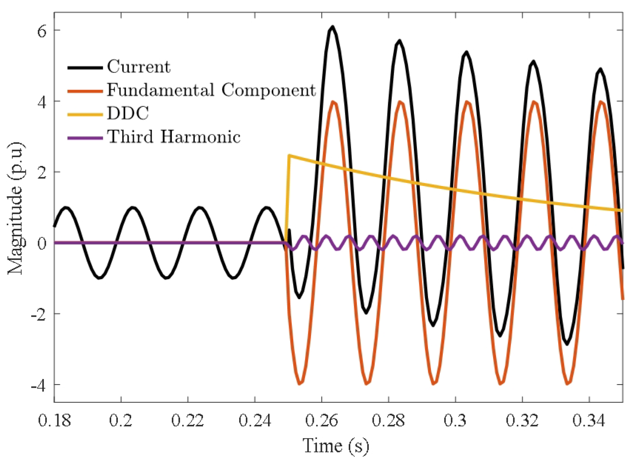
The above-mentioned equations show the mathematical equations of the DDC appearance in FC. In the general form, the current waveform is not zero before the fault occurrence, and the FC includes different components, as shown in Figure 2. The current waveform is free of DDC in the pre-fault condition. In the post-fault condition, DDC and high-order harmonics appear in the signal. The yellow line depicts the DDC component after the fault, which acts similar to an exponential with a specific amplitude and time constant (TC). The main purpose of mitigation methods is to eliminate DDC in the presence of harmonics and noise to obtain a pure sinusoidal signal (see Figure 2). Then, the phasor estimation applied without any errors results in a secure protection system. In fact, DDC removal has been proposed to improve the performance of protection systems by eliminating the effects of DDCs while increasing the reliability/sensitivity of existing distance protection methods to meet common standards, such as IEEE c37.
In previous years, numerous methods have been introduced to tackle the DDC phenomenon. Most methods are proposed to eliminate DDC based on the discrete Fourier transform (DFT) method. Least-squares (LS) methods are other schemes that have been used as powerful tools in phasor estimation applications. These methods are based on predefined signals and some approximations in their calculations to obtain phasor quantities of the voltage or current. Artificial intelligence (AI) is a new tool in science and technology that has appeared in recent years; it also applies to various applications and accurate phasor estimation (DDC-free).

1.2. Contributions

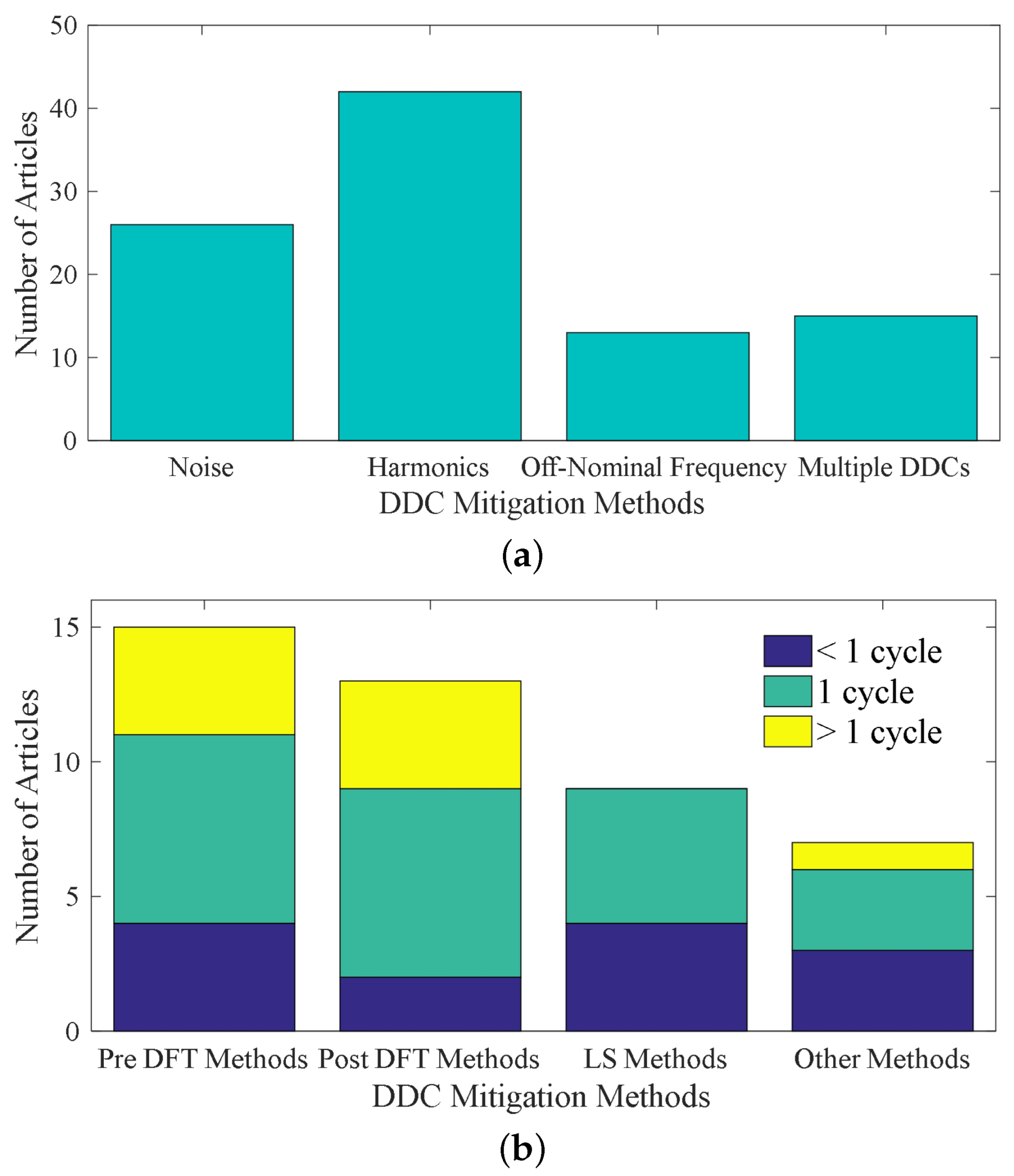
To the best of the authors’ knowledge, only two conference papers have reviewed DDC mitigation methods [4,5]. In [4], only six methods were considered for evaluation and some limited statistical comparative results were given. In [5], the authors evaluated a group of methods through simulation results, proposing analytical solutions for both primary and auxiliary DDCs. Thus, the previous works in this field are limited and could not provide a clear point of view on DDC mitigation methods. This is the main reason we conducted an up-to-date review of DDC mitigation methods in this paper (i.e., to present a comprehensive investigation and to provide guidelines for future research). To address this issue, four main categories for DDC mitigation were considered—DDC mitigation before DFT, after DFT, least square-based (LS-based) methods, and other heuristic methods (see Figure 3). In the first group, DDC was eliminated before the DFT process and a pure sinusoidal signal was used as an input for DFT. DDC is estimated based on the fundamental frequency components, which are calculated through DFT in the second group. LS-based methods use a new procedure to estimate DDC and current harmonics, simultaneously using error minimization by a specific set of data. Other methods apply various heuristic methods, such as AI, the neural network, and the frequency domain analysis to estimate the DDC parameters. Some general statistics are presented in Figure 4 for different DDC mitigation methods. In this paper, all of the above categories are discussed to indicate the advantages/disadvantages precisely.
This review paper evaluates a large number of methods, including four groups in the field of DDC mitigation through precise analysis and fruitful comparisons. The contributions of this paper are as follows:
  • We present a comprehensive review of DDC estimation methods (including four categories) to present an extensive comparative analysis by addressing the main advantages/disadvantages of each category.
  • We provide an overview of the DDC estimation accuracy of different methods in the presence of destructive factors: harmonics, noise, off-nominal frequency (ONF), and multiple DDCs (MDDCs), and nominate the best DDC mitigation methods in each category.
  • We investigate some selected schemes to identify their efficiencies through computer simulations.
  • We propose guidelines for future research in this field.

1.3. Article Organization

This paper is organized as follows. The DFT analysis in the current phasor estimation is presented in Section 2. Pre-DFT DDC mitigation methods are discussed in Section 3. Post-DFT schemes are analyzed and considered for investigation in Section 4. Section 5 is dedicated to LS-based methods, where different approaches, including conventional and new methods, are presented, and a detailed review is proposed. Other methods are discussed in Section 6. Guidelines for future works are presented in Section 7. Finally, the paper is concluded in Section 8.

2. DFT Analysis in Current Phasor Estimation

DFT is a powerful method in digital signal processing, which is used to separate all of the components of a unique signal in the frequency domain. DFT decomposes all of the non-separable time domain components of a specific signal into separable signals in the frequency domain. Features (e.g., immunity from harmonics, fast response, and simplicity) introduce DFT as a suitable approach for a broad range of applications, including power system measurements and protection. DFT functions can be defined as follows:
X k = n = 0 N 1 x [ n ] e j 2 π N k n = n = 0 N 1 x [ n ] cos ( 2 π N k n ) j sin ( 2 π N k n )
where x [ n ] is a complex sequence of numbers k = ( 0 , , N ) , n is the number of samples, and N is the maximum number of samples in a certain sampling frequency. The FC signal can be written as follows in the general form:
i [ n ] = i A C [ n ] + i D C [ n ] = n = 1 M I h sin 2 π N k n + θ n + I 0 e n Δ t τ
where i A C [ n ] is the sinusoidal part of FC, i D C [ n ] is the DDC, I h is the amplitude of the hth harmonic component, M is the maximum harmonic order, θ n is the phase angle, I 0 is the amplitude of the DDC current, and τ is the time constant of DDC. Hence, the DFT of FC for the main frequency component obtains:
I D F T 1 s t = I 1 sin 2 π N n + θ n e j 2 π N n + I 0 e n Δ t τ e j 2 π N n = I ^ 1 + Δ I D D C
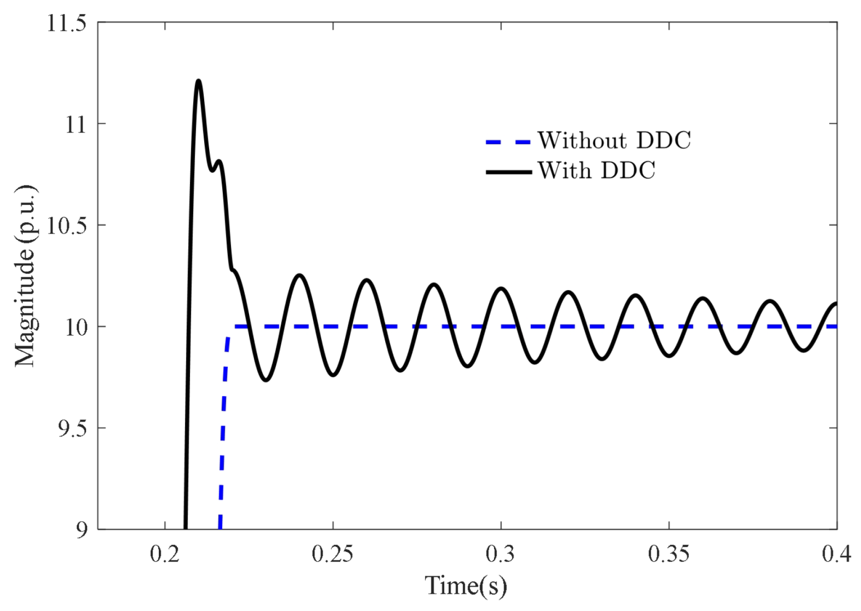
Based on Equation (5), DFT in the presence of DDC has a certain amount of errors, which endanger protection systems. Figure 5 shows the amplitude of a typical FC signal in the presence of DDC. As Figure 5 shows, the amplitude of the main frequency component contains a large overshoot with DDC, which endangers the protection system, especially distance relays to discriminate in/out of zone faults. Therefore, the DFT method is not a reliable solution for phasor estimation in the presence of DDC. This is the main motivation to explore new solutions for this concern.

3. Pre-DFT Methods

3.1. A Brief Survey on the DDC Mitigation in Pre-DFT Methods

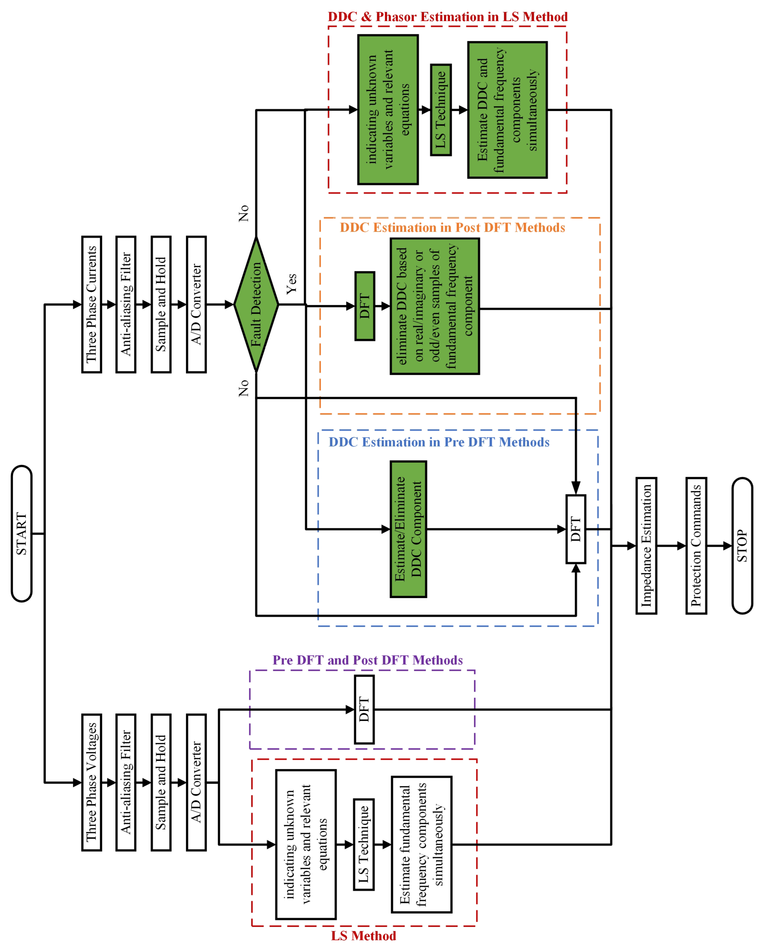
As mentioned in the previous section, DFT is widely used as a powerful tool for phasor estimation. Simplicity, immunity from high-order harmonics, and fast responses are the unique features of this method [1]. However, DFT cannot attenuate the DDC since it does not affect the low-frequency signals (see Equation (5)). Few practical methods have been proposed to estimate and eliminate DDC before DFT. In this category, the distorted FC signal is taken into account for DDC mitigation, which prepares a non-DDC signal for the DFT process. These methods remove the DDC through a certain procedure, which is shown in Figure 6. Figure 6 depicts the overall voltage/current phasor estimation in a measurement/protection system, where both voltage and current signals are filtered through anti-aliasing filters and analog-to-digital converters to prepare for further steps in the phasor estimation procedure.
The following FC formula is considered for all further simulations in this paper.
i ( t ) = I 0 e t / τ p + 0.35 I 0 e t / τ s + I 1 sin ( ω t + θ 1 ) + I 3 sin ( 3 ω t + θ 3 ) + W
It should be noted that Equation (6) is an expanded form of Equation (4) (but in continuous form), which consists of primary and secondary DDCs, first and third harmonic components (higher orders are neglected for the sake of simplicity), and the noise signal.
Table 1 shows the overall parameter information. Higher-order harmonics are filtered through proper anti-aliasing low-pass filters [1]. Moreover, the second DDC may be added due to the presence of the current transformer in protection systems [6], which was considered in the test results. The amplitude of this signal is commonly lower than the main DDC and its time constant is larger than the main DDC parameter (20 cycles were considered in this paper). The root-mean-square error (RMSE) is an appropriate index to show the accuracy of estimations in such problems. The RMSE represents the square root of the second sample moment of the differences between the predicted and the observed values or the quadratic mean of these differences and was calculated for five cycles after the fault inception in all methods. In all cases, the fundamental frequency and sampling frequency were set to 50 Hz and 1 KHz (20 samples per cycle), respectively. To show a comparative analysis, previous studies only considered phasor estimation quantities, which may not be the best parameter. As a result, only DDC estimation accuracy was examined in the evaluation results to achieve more accurate and precise comparisons in the four different categories.
The Cosine filter is proposed in [7] to remove DDC before the DFT process. This method shifts the current waveform (a quarter cycle) and then removes DDC from the main signal based on differentiation. Moreover, it can be used as a pre-processing filter for LS or Kalman filter methods [2]. The Cosine filter is a well-known method that is widely used in commercial relays for DDC mitigation. The Cosine filter FC signal is as follows:
i C S = 2 N k = 1 N i ( t ) c o s ( k ω Δ t )
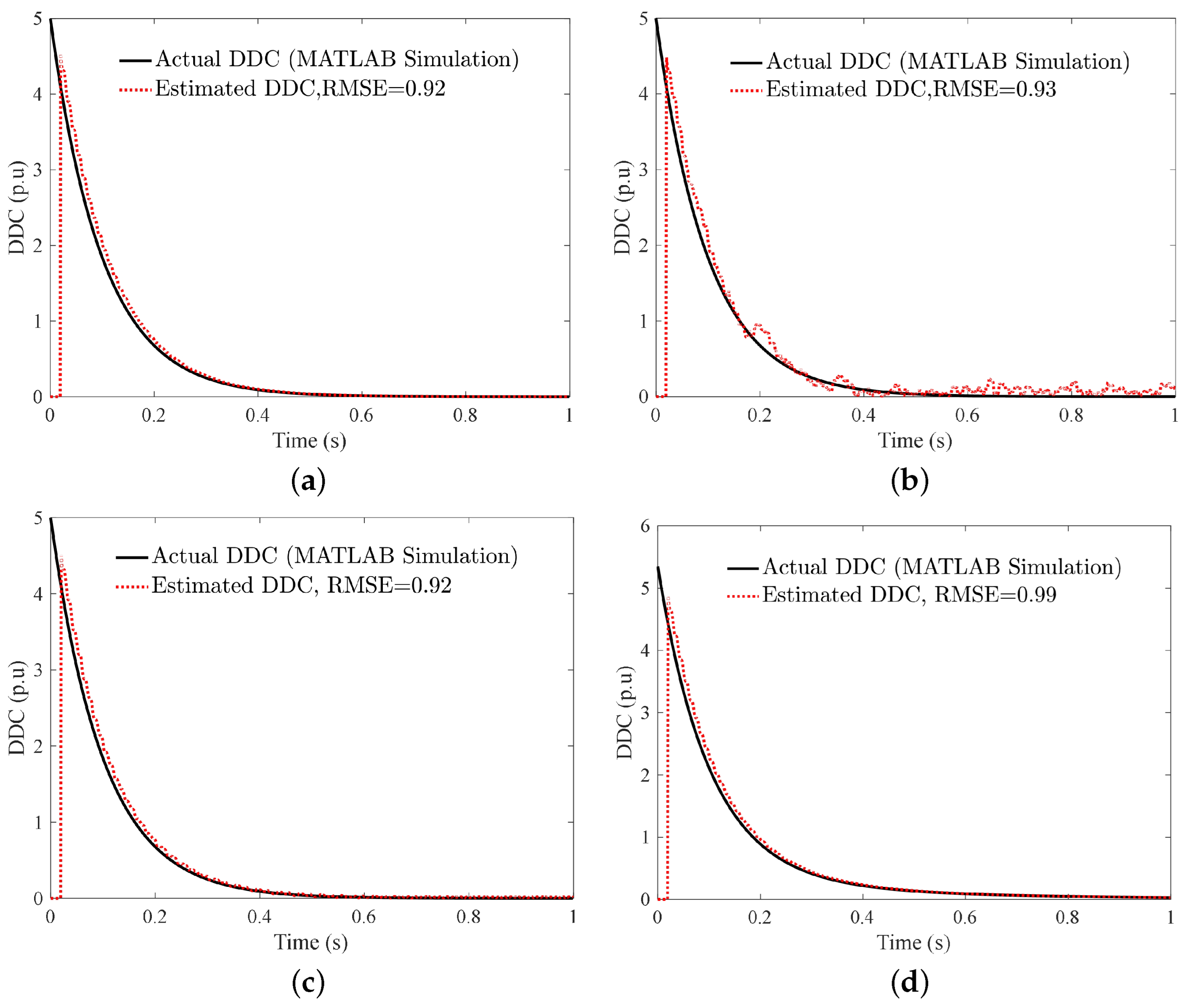
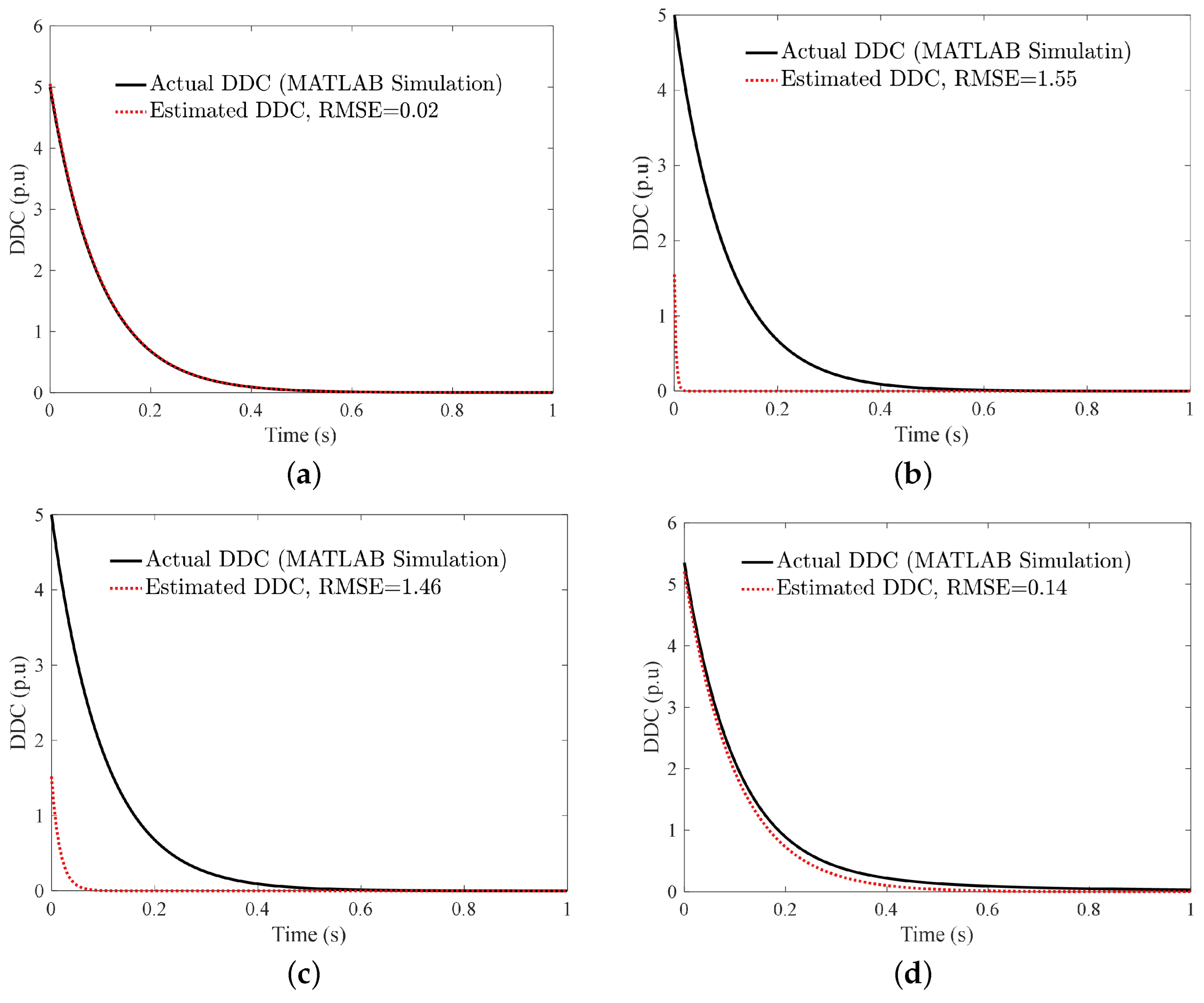
As shown in Figure 7, the cosine filter performance was analyzed in the DDC estimation. Moreover, noise, ONF, and MDDCs were investigated through simulation studies. A quarter-cycle delay of the method is evident in the results. In addition, estimated DDCs have some fluctuations in case of noisy conditions and may cause inaccuracy in phasor estimation.
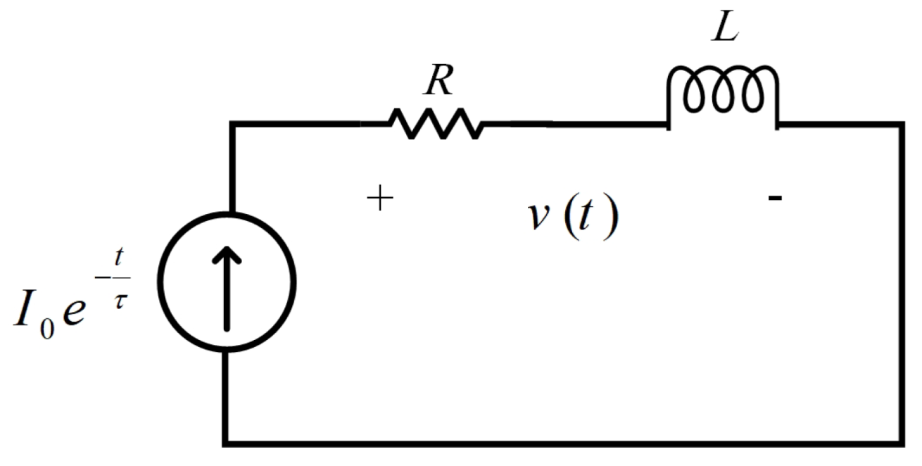
In [2], a mimic filter was introduced to suppress the DDC effect on the FC waveform. At fault inception, the current acts similar to an impulse signal, which can be investigated through a mimic circuit. The mimic circuit is a resistive–inductive circuit where a current source supplies the circuit. The values of R and L (in the mimic circuit) are equal to grid parameters. The mimic circuit acts similar to a high-pass filter and attenuates low-frequency signals and DDC. In the Laplace domain, the voltage across the circuit is clear from the DDC part in case of an impulsive input signal (see Figure 8). The voltage across the mimic circuit is calculated as follows ( τ = L R ) [8]:
v ( t ) = K R i ( t ) + K L d i d t = K R I 0 e t τ + K L I 0 d d t e t τ = K R I 0 e t τ K L I 0 1 τ e t τ = K R I 0 e t τ K L I 0 R L e t τ = 0
which K is a certain coefficient of the filter, which has been calculated for the unity gain in the fundamental frequency harmonic. As Equation (8) shows, the DDC current is discarded from the main signal. This method needs one and a quarter of the cycle current samples for the DDC estimation.
In [9], the DDC is estimated based on the Park transform (PT) of the current signal. The PT is written as follows:
P = 2 3 sin ω t sin ( ω t + 2 π 3 ) sin ( ω t + 4 π 3 ) cos ω t cos ( ω t + 2 π 3 ) cos ( ω t + 4 π 3 ) 1 2 1 2 1 2 P 1 = 3 2 sin ω t cos ω t 1 2 sin ( ω t + 4 π 3 ) cos ( ω t + 4 π 3 ) 1 2 sin ( ω t + 2 π 3 ) cos ( ω t + 2 π 3 ) 1 2
PT parameters are DC values during normal operation of the power system, but these values oscillate in the fault condition. In [9], a moving average filter was used to eliminate DDC from the PT quantities. The average of the PT parameters was equal to DDC in each period:
I d D C = 1 N n = 1 N I d ( n ) I q D C = 1 N n = 1 N I q ( n ) I 0 D C = 1 N n = 1 N I 0 ( n )
Filtered signals are transformed to the ABC frame by the inverse PT. Finally, the amplitude and phase angle of the main harmonic were computed through the LS technique. This method is only applicable in the three-phase applications, where all currents are available. Thus, it is an inherent drawback of the method.
Three consecutive partial sums of the FC waveform were considered to estimate DDC in [10]. In all of the partial sums, a small residual quantity appeared, which was ignored for the sake of simplicity. This method is very simple and needs a cycle of data for phasor estimation.
To decrease the error of approximation in [10], the summation of odd and even values of the FC signal was used for DDC estimation in [11]. Using this method, DDC parameters were obtained without any extra data or calculations. Moreover, three simplification methods were introduced to decay the computational burden in real manipulation, and the LS method was considered for DDC approximation. Figure 9 shows the comparative simulation results for the method in [10,11]. The results show that both methods have high efficiency in DDC estimation. However, the method in [10] has lower sensitivity to noise and higher sensitivity to ONF.
In [12], an integral-based method is introduced for DDC estimation before DFT. The integral of the sinusoidal components in one cycle is equal to zero. Therefore, only the integral of the DDC parameter remains, which is as follows:
t T t i ( t ) d t = t T t I 0 e t / τ + k = 1 P I k sin ( k ω 1 t + θ k ) d t = t T t I 0 e t / τ d t = I 0 τ e t / τ ( 1 e T / t ) = Z ( t )
applying the second integral after a step time ( Δ t) yields:
Z ( t + Δ t ) = I 0 τ e ( t + Δ t ) ( 1 e T / τ ) = I 0 τ e ( t / τ ) ( 1 e T / τ ) e Δ t / τ = Z ( t ) e Δ t / τ
Then:
τ = Δ t ln Z ( t + Δ t ) Z ( t ) I 0 = Z ( t ) τ e t / τ ( 1 e T / τ )
As shown in Equation (13), DDC parameters were obtained by two consecutive integrals.
Another integral-based method is proposed in [13]. This method uses a simple procedure for DDC estimation before the DFT process. The symmetrical wave shape in a sinusoidal signal is the key point that is taken into account. Two samples with a cycle interval have the same amplitude in a periodic signal. The study presented in [13] uses this fact as well as the FC integration in one cycle to obtain the DDC parameters; this method uses the first two terms of the Taylor series expansion for DDC approximation. The integral of FC with DDC approximation is written based on Equation (11):
S = I 0 T 1 2 I 0 τ ( T 2 + 2 t 0 T )
where t 0 is the fault inception time and:
I 0 τ = i ( t 0 ) i ( t 0 + T ) T I 0 = S + ( 1 / 2 ) ( I 0 / τ ) ( T 2 + 2 t 0 T ) T = S + ( 1 / 2 ) ( i ( t 0 ) i ( t 0 + T ) ) ( T + 2 t 0 ) T
then:
τ = S + ( 1 / 2 ) ( i ( t 0 ) i ( t 0 + T ) ) ( T + 2 t 0 ) i ( t 0 ) i ( t 0 + T )
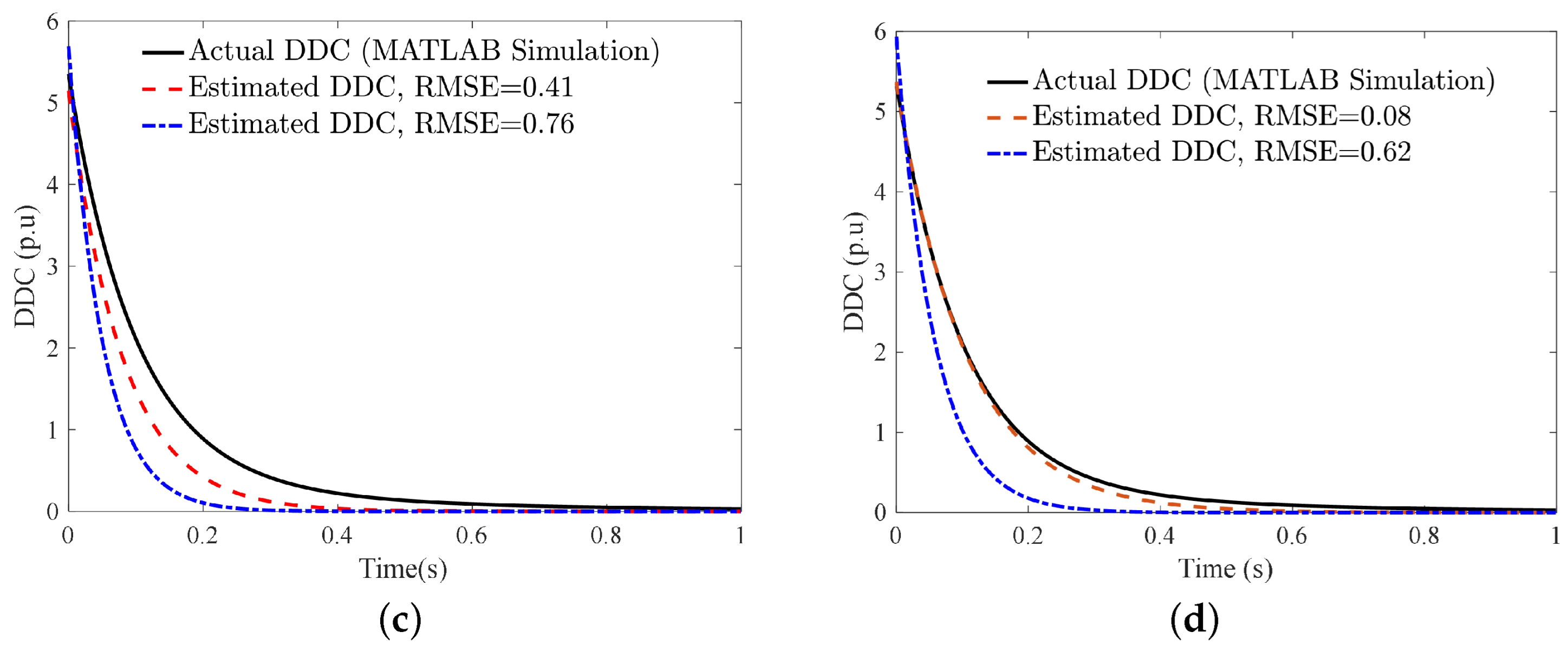
Figure 10 shows the comparative simulation results for the method in [12,13]. The method in [12] has the lower RMSE (error) compared with the method in [13]. Noise sensitivity is lower than ONF and the MDDC error for both methods.
The Prony-DFT method was investigated to enhance the direct Prony scheme for DDC estimation in [14]. In this method, the effects of noise and harmonics were removed using a forward average filter in the first step. The Prony method extracted the DDC parameters from the average value of the FC signal over one cycle. Then, DDC was subtracted from the main signal and DFT was applied on the filtered signal as the last step. The Prony method acts similar to DFT to extract components of a uniformly sampled signal by using a proper fitting criterion.
In [15], an improved Prony method based on [14] is presented, where the transient signal parameters are updated without any approximation due to discretization. In fact, the moving average filter is redesigned for this purpose. This method is applicable in series compensated lines and needs one cycle of current samples for DDC estimation.
In [16], a method is proposed for DDC estimation using Hilbert transform (HT), which shifts the FC 90 degrees in the frequency domain. Two consecutive HTs were used to remove the DDC in the resultant equations. A cycle plus three samples were considered for calculations.
An auxiliary signal was generated in [1], which acted similar to a high-pass filter for the DDC calculation. This method used a hierarchical procedure, including the summation of both FC and an auxiliary signal, DFT error calculation, and DDC mitigation. The auxiliary signal was as follows:
y [ n ] = ( 1 ) n [ i D D C [ n ] + i A C [ n ] ] i [ n ]
Then, S1 and S2 were obtained:
S 1 = n = 1 N i [ n ] = n = 1 N i D D C [ n ] = I 0 1 e T Δ t / τ 1 e Δ t / τ S 2 = n = 1 N y [ n ] = n = 1 N ( 1 ) n i [ n ] = I 0 1 e T Δ t / τ 1 + e Δ t / τ
which yields:
e Δ t / τ = S 1 S 2 S 1 + S 2 I 0 = 1 e Δ t / τ 1 e T Δ t / τ S 1
As a new version of [1], a new auxiliary signal was used in [6], which discarded the odd-numbered samples from the FC. Discarding the odd-numbered samples is a heuristic approach to finding the time constant of the DDC and it has no impact on the accuracy. This method is called the high-frequency downsampling method. The auxiliary signal is as follows:
y [ n ] = 1 + ( 1 ) n 2 [ i D D C [ n ] + i A C [ n ] ] i [ n ]
S1 is the same as Equation (18) and S2 is:
S 2 = n = 1 N y [ n ] = n = 1 N 1 + ( 1 ) n 2 i [ n ] = I 0 1 e T Δ t / τ ( 1 + e Δ t / τ ) ( 1 + e Δ t / τ )
which yields:
e Δ t / τ = S 1 S 2 1 I 0 = 1 e Δ t / τ 1 e T Δ t / τ S 1
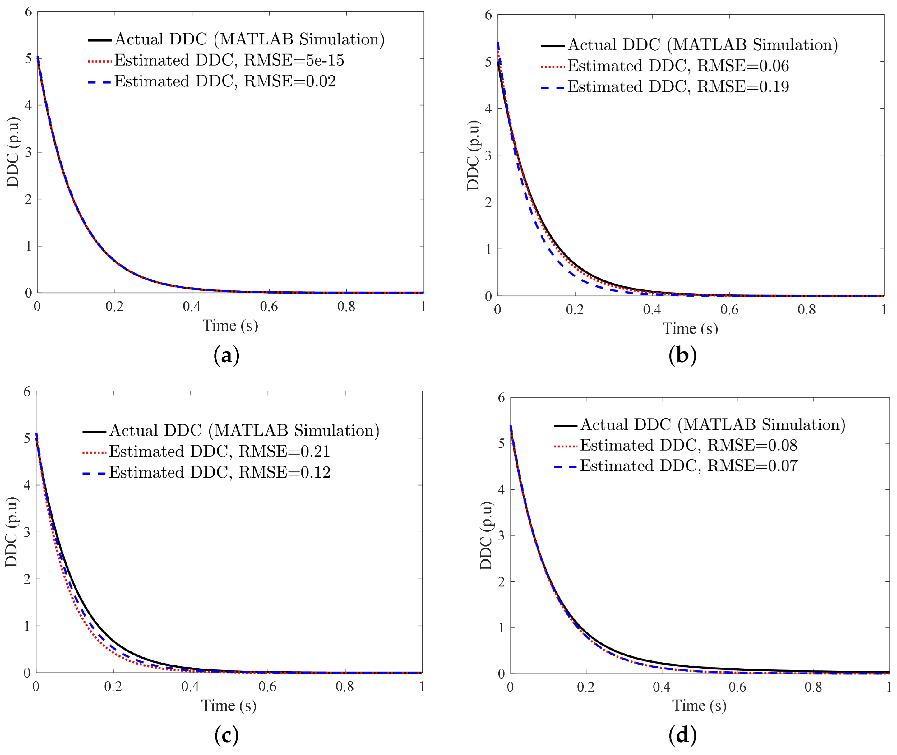
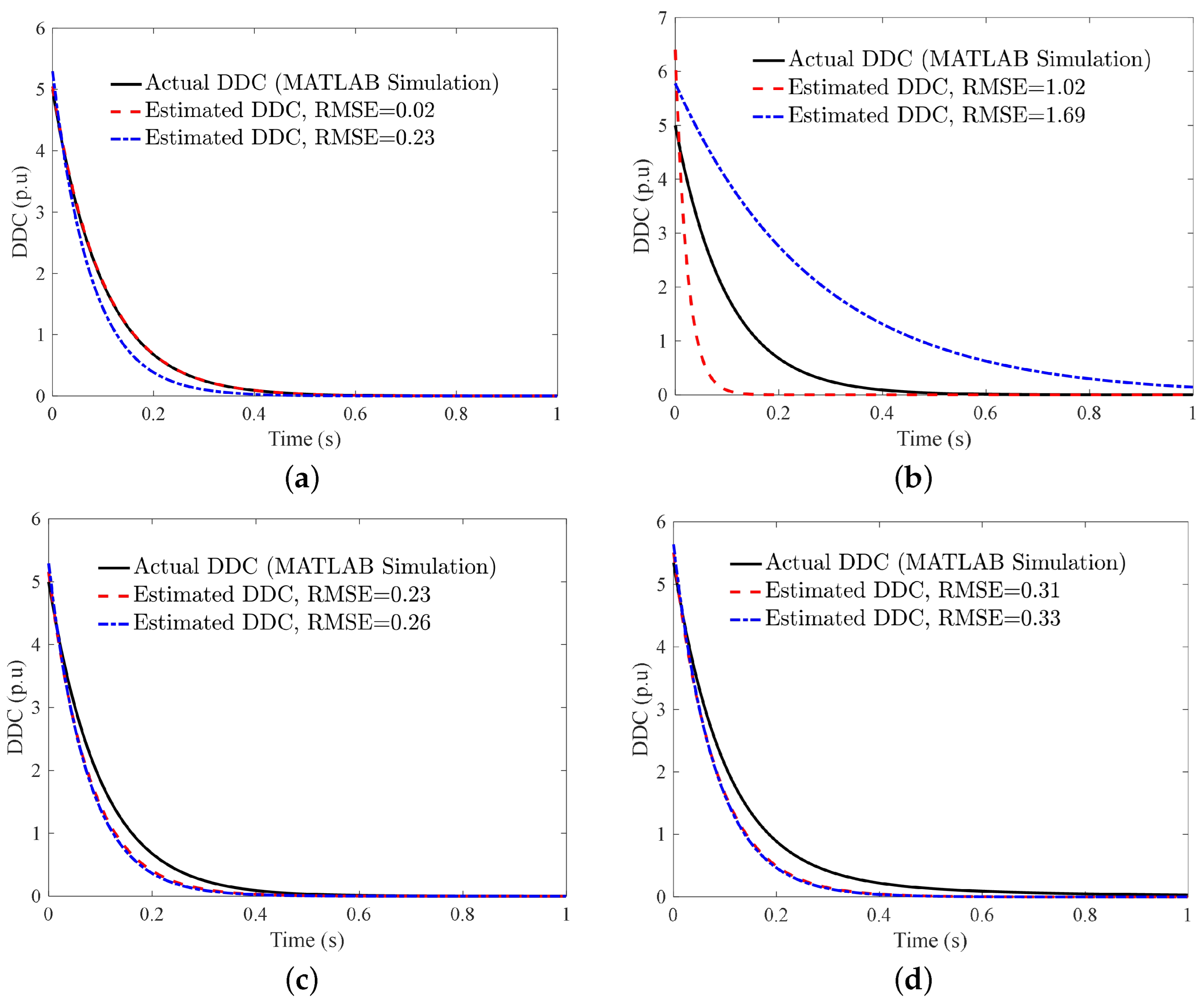
Figure 11 shows the comparative simulation results for the method in [1,6]. These two methods have the same performance in the DDC estimation since the mathematics behind them are analogous. Noisy signals decay the estimation accuracy more than other destructive factors.
The intrinsic time-scale (ITD) decomposition is a strong data-driven method used in signal processing applications. In [17], this method is applied to extract DDC from the main current. The ITD tool decomposes a non-stationary signal into a proper rotation component (PRC) and a monotonic trend (MT) signal. PRC indicates the fundamental harmonic of FC, which is used as an input for DFT, while MT obtains DDC.
A sub-cycle-sample method is introduced in [18], which needs four samples of FC to indicate DDC. The method triggers when a half-cycle plus two samples are recorded. Then, DDC parameters are calculated through solving a linear equation. DDC parameters are as follows [18]:
e Δ t / τ = i ( 2 ) + i T 2 + 2 i ( 1 ) + T 2 + 1 I 0 = i ( 1 ) + T 2 + 1 e Δ t / τ + e ( T 2 + 1 ) Δ t / τ
The trapezoid rule is used to estimate the DDC parameters in [3]. Two consecutive half cycles of a periodic signal are equal but with opposite signs. This fact is used to determine the DDC parameters, which are obtained as follows:
e ( Δ t / τ ) = k = n + 1 n + 2 i [ n ] + k = n + 1 + N / 2 n + 2 + N / 2 i [ n ] k = n n + 1 i [ n ] + k = n + N / 2 n + 1 + N / 2 i [ n ] I 0 = k = n n + 1 i [ n ] + k = n + N / 2 n + 1 + N / 2 i [ n ] e n Δ t / τ + e ( n + 1 ) Δ t τ + e ( n + N / 2 ) Δ t τ + e ( n + 1 + N / 2 ) Δ t τ
This method needs a half-cycle plus three samples and is only valid in full-cycle DFT (FCDFT) applications. Figure 12 shows the comparative simulation results for the method in [3,18]. It is clear that noise sensitivity was very high in both methods since a small number of samples were considered for the DDC parameter estimation. However, accuracy was maintained at a good level under other destructive conditions.
A novel sub-cycle method, which is an improved version of [18], is presented in [19]. The peak value of the sinusoidal signal (FC in this case) was considered to obtain four consecutive samples. Using this method, DDC was determined through the difference between these samples. The Savitzky–Golay filter was used to remove noise since this method is only applicable for noiseless signals. It is shown that the maximum number of samples is required for the 3 π 2 radian phase angle, which equals a half cycle plus two samples.
An updated version of [1] is presented in [20], where three consecutive samples of an average filter were used to compute DDC parameters. Then, by solving two quadratic equations, DDC parameters were obtained. MDDCs were analytically considered in this method. One data cycle was required for all calculations.
A second-order derivative was used to remove the DDC effect before DFT in [21]. The main idea is that the summation of FC and its second derivative for the fundamental frequency component could be used to delete sinusoidal parts of the main signal. High-order harmonics and noise effects were eliminated from the FC using a Butterworth low-pass filter and a three-sample-based moving average filter. FC and its second derivative could be written as follows:
i ( t ) = I 0 e t / τ + I 1 sin ( ω t + θ 1 ) 1 ω 2 d 2 i ( t ) d t = 1 ω 2 τ 2 I 0 e t / τ I 1 sin ( ω t + θ 1 )
summing the above equations:
i ( t ) + 1 ω 2 d 2 i ( t ) d t = I 0 e t / τ ( 1 + 1 ω 2 τ 2 ) Δ
where Δ is approximately equal to one as verified in [21]. Thus, DDC is estimated through Equation (26).

3.2. Critical Review of Pre-DFT Methods

Seventeen methods were considered to evaluate pre-DFT DDC mitigation methods. Various mathematical approaches based on FC characteristics were introduced to tackle unwanted DDC signals. Four destructive factors, which indicate the efficiency in DDC mitigation methods, were introduced to evaluate the method’s efficiency. Table 2 summarizes pre-DFT methods, including/excluding these factors, as well as sample requirements. ONF and MDDC were investigated in 56% and 36% of pre-DFT methods, respectively. Moreover, MDDCs were not included in an analytical approach in most of the methods. Thus, it is clear that the lack of ONF and MDDC mathematical modeling in the problem statement decayed the accuracy of the DDC estimation. In this section, a critical review of the different pre-DFT methods and some of the main drawbacks are presented.
The very first attempts for DDC mitigation are introduced by using two innovative filters [2,7]. Both cosine and mimic filters have presented a simple approach for the accurate phasor estimation, free from the DDC effect. In addition, the cosine filter can be nominated as the simplest method among others since it does not require high/complex calculations or any extra filters. However, it needs 1.25 cycles of data for DDC estimation, which is high compared to the new methods and causes more delay in the processes. On the other hand, the mimic filter is only applicable for a specific TC, which is equivalent to TC of the network (X/R ratio). Thus, it is not a promising method for erasing the DDC effect for a range of various TCs.
In [10], partial sums of the current signals were used to find the DDC parameters, while some residual values were neglected during calculations. Method [11] only needs one cycle of data; it does not need any complicated computations. It is less sensitive to noise because of sample summation and can be utilized in real applications.
In subsequent steps, integration of the FC signal over one cycle is recognized as a prominent way to estimate DDC [12,13]. In these methods, the effect of high-order harmonics are cleared completely since all periodical signals have zero quantity in one period integration. However, DDC approximation using the Taylor series expansion decays the method’s accuracy, especially in small TCs. In addition, noise vulnerability is very high in [13] since only a two-sample differentiation is considered in the DDC estimation.
The PT method [9] uses an average filter over the fundamental phasor, which removes the oscillating part from the Park quantities. However, it cannot attenuate the oscillating signal effectively since the signal overshoot is more than 15% in severe cases [3]. Moreover, in case of asymmetrical faults, a twice nominal frequency signal appears in the dq0 quantities. Thus, the fundamental frequency average filter does not affect it and this method is not applicable to all types of FCs. In addition, all three phase currents should be available for computing dq0 quantities.
Prony DFT methods are introduced in [14,15]. The Prony function is similar to a DFT, which builds a series of damped exponential/sinusoidal signals based on the main signal to estimate frequency, amplitude, phase angle, or damping components, such as DDC. A forward-moving average low-pass filter was used for removing sinusoidal components as well as the noise effect. This filter increases the delay in the phasor estimation process. Moreover, the noise effect is not deleted completely and discrete approximation cuts down the accuracy in [14]. However, the complexities in Prony DFT methods are low, which is a positive feature.
HT is used in [16] to remove DDC by applying phase shifting in the FC signal. HT obtains zero quantity for DC values, which is a key point for DDC mitigation. MDDCs are investigated analytically in this method. However, the computational complexity is high due to multiple mathematical functions, including recursive equations.
A high-pass filter and high-frequency downsampling are two innovative methods that are based on the integration of modified current signals [1,6]. These methods are absolutely vulnerable to noise since they magnify high-frequency signals. Moreover, MDDCs could not be analyzed analytically through these methods. However, these methods are very simple and straightforward and eliminate harmonics completely.
The ITD decomposition method is proposed in [17] as a powerful filtering method in signal-processing applications. This method estimates DDC and fundamental phasor component simultaneously. It needs a low-pass filter for filtering FC in the pre-processing step.
In [18], the authors used four samples as part of the sub-cycle method (with minimum samples compared to the others). However, noise vulnerability was maximized.
Method [20] is a hybrid method, which is conducted based on [13,16]. This method attenuates the noise effect based on the average filter but increases the computational burden because of three consecutive average filtering and solving quadratic equations. The trapezoid rule [3] is used as a reliable method to decrease the noise sensitivity in sample-based methods. Using a set of consecutive samples to calculate DDC parameters decreases the noise effect efficiently. Moreover, ONF has been investigated through simulations but in a non-analytical approach.
The salient advantages of the method found in [21] include the low number of FC sample requirements for DDC elimination, as well as simplicity, and the two damping filters included for harmonics/noise rejection, which impose delays to overall computations.
Based on intensive discussions and simulations, which are presented above in the case of the pre-DFT methods, methods [10,12] are nominated as the best DDC mitigation methods. Based on simulation results, the minimum RMSE is dedicated to [10], which distinguishes this method as the most reliable scheme in this category. Method [12] was investigated as a novel approach that highly attenuates the noise effect, unlike other methods, by considering a cycle of samples. This method is very simple without any complicated mathematical functions.
The main advantages and drawbacks of pre-DFT-based methods are as follows:
Advantages:
  • Diverse sets of mathematical solutions are open to discovering.
  • The majority of methods in this group are simple and suitable for real implementation.
  • Sample-based methods use a minimum number of samples for DDC estimation.
  • DDC parameters are obtained directly (unlike post-DFT methods).
Drawbacks:
  • Most of the methods are sensitive to noise and need extra filters for noise attenuation.
  • MDDC investigations are absent in this category, except for a few methods.
  • Harmonics should be discarded before DDC estimation using low-pass filters that add extra delays to the whole process.

4. Post-DFT Methods

4.1. A Brief Survey on the DDC Mitigation in Post-DFT Methods

DFT is widely used in phasor estimation in real applications. One of the salient features of this method is immunity from harmonics distortions. Therefore, the fundamental current component can be easily extracted by DFT. This positive characteristic is used in many post-DFT DDC mitigation methods using real/imaginary or odd/even samples of this function. Post-DFT methods are introduced and discussed intensively in the following paragraphs. These methods remove the DDC through a certain procedure, which is shown in Figure 6.
In [22], a novel scheme is proposed, which uses real and imaginary parts of DFT of current signals to estimate DDC. FCDFT and half-cycle DFT (HCDFT) are considered for estimation, in which one/half cycle plus two samples are needed for DDC calculations, respectively. Moreover, another half-cycle DFT-based method was proposed in this paper, which requires a half cycle plus three samples to evaluate DDC. For FCDFT, the DDC parameters are as follows:
e Δ t / τ = Z r e a l ( T + 2 Δ t ) Z r e a l ( T + Δ t ) cos 2 π T Z r e a l ( T + Δ t ) Z r e a l ( T ) cos 4 π T I 0 = T Z r e a l ( T + Δ t ) Z r e a l ( T ) 2 cos ( 2 π T ) e Δ t / τ ( e T Δ t / τ 1 )
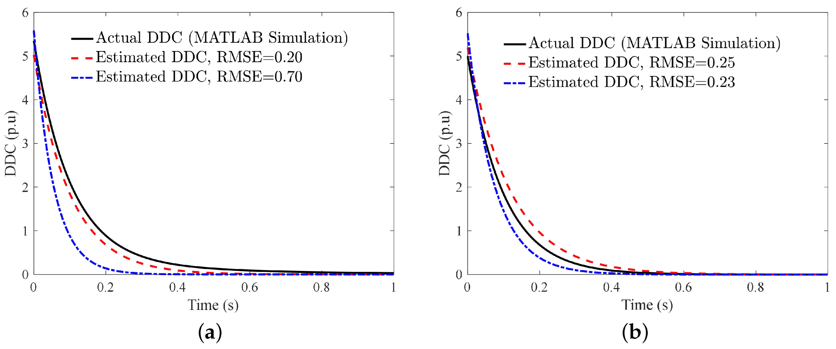
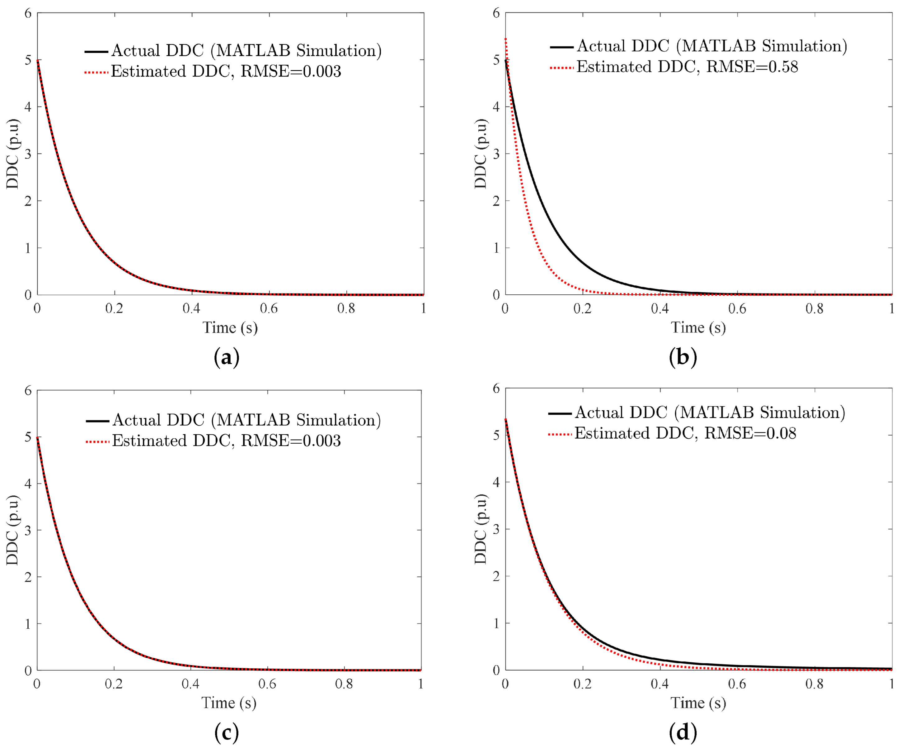
Figure 13 shows the simulation results for the method in [22]. As it is shown, noisy signals (and ONF) highly attenuate the estimation accuracy. Furthermore, the results verify that post-DFT methods are really vulnerable to ONF since the basis of DFT is based on frequency consistency.
A modified HCDF/FCDFT method is proposed in [23], which is a new version of [22] where analog low-pass filters are added. Analog low-pass filters with cut-off frequencies of 30 and 60 Hz are considered for high-order harmonics rejection in voltage and current signals, respectively. This method needs one and three-eighths of a cycle for DDC estimation.
A smart DFT method was developed using DFT to completely eliminate DDC by an analytical approach [24]. This method uses forward recursive DFT to calculate DDC parameters by solving a second-order polynomial equation. Moreover, a smoothing filter is used to attenuate the noise effect. One cycle plus two samples are used for DDC cancellation in [24].
The weighted LS method was used in [25] to obtain phasor components of fundamental frequency without any DDC effect. After applying DFT, the real and imaginary parts of the fundamental signal were used as unknown parameters in the LS estimation method. Two modification functions were considered through a recursive form to compute the unknown parameters. This method uses one cycle of samples for computations.
In [26], an updated version of the method in [11] was proposed, where CT saturation was added to the problem model. Then, the LS method was applied twice to find the DDC and phasor components. One data cycle is required for this method.
A novel method for DDC mitigation in series-compensated transmission lines was proposed in [27]. Real and imaginary parts of the DFT based on a recursive method were used to determine DDC parameters in case of low/high impedance faults and MDDCs. This method uses three different approaches to obtain DDC parameters after applying DFT. It needs one cycle plus four samples for four consecutive DFT calculations in the least possible case. In [14,15,27], sub-synchronous resonances, which are the results of interactions between synchronous generators and transmission lines (series compensated lines), were addressed. This causes the appearance of sinusoidal damping signals in the fault current, which is a special case in the DDC investigation. Thus, this phenomenon was not considered in this paper.
A modified half/FCDFT method based on the adaptive mimic filter is presented in [28]. This method uses both voltage and current signals for phasor estimation in the presence of DDC. The time constant of DDC was obtained and substituted in the equations for the accurate phasor estimation. The angle difference of FC and voltage signals determines TC of DDC:
ϕ = V I τ = tan ϕ ω 1
Even and odd sample sets of the DFT process were considered for DDC mitigation by using a recursive relationship between them [29]. In this method, only DDC TC was calculated directly; the DDC amplitude computation was not necessary for the accurate phasor estimation. Method [29] needs one cycle for DFT calculations. E = e Δ t / t was obtained as follows:
E = K I m K R e sin ( 2 π N ) K I m cos ( 2 π N ) K R e = R e { I D F T e v e n I D F T o d d } K I m = I m { I D F T e v e n I D F T o d d }
where R e { . } and I m { . } denote real and imaginary functions in the above equation, respectively. Then, the fundamental phasor component is computed as:
I D F T 1 s t = I D F T I D F T D D C I D F T D D C = I D F T e v e n I D F T o d d 1 + E j 2 π N 1 E j 2 π N
Similar to [29], even and odd samples of an FCDFT were used to attenuate the effects of DDC [30]. In this method, DDC parameters were not recognized directly. However, as shown in [30], the effect of DDC was decreased by a certain coefficient. This method only needs a full cycle of samples for its calculations. The fundamental phasor amplitude is:
| I D F T 1 s t | = | I D F T e v e n I D F T o d d | 2 sin π N
S-Charm DFT was suggested in [31], proposing an auxiliary signal that discarded the noise and DDC from the fundamental frequency component after the DFT process. Two modification coefficients were considered for amplitude and phase angle estimations, which were optimally calculated for different values of sampling. This method needs one data cycle for DDC elimination.
A fully analytical method based on integration and a half-cycle DFT is proposed in [32], which needs a half-cycle plus three samples for three consecutive integrations to estimate DDC parameters. Moreover, the method is able to estimate frequency at the same time.
A new DFT-based method with a second-order FIR notch filter has been proposed to estimate phasor quantities in the case of MDDCs and a bias DC value [33]. The filter combines MDDCs and bias DC into a unique DDC and minimizes the burden of computations. This method is applicable in both full/half cycle DFTs and uses a cycle plus two samples in its algorithm.
An auto-regressive method for removing DDC effects is proposed in [34]. The second-order derivative of the current signal is the primary part of this method to expand the fundamental phasor quantity based on three consecutive DFTs. Therefore, a cycle plus one sample is necessary for its calculations.
A linear polynomial equation is solved based on real/imaginary even/odd components of a half-cycle DFT method [35]. Based on a recursive method, two equations for each real and imaginary part of the phasor estimation were obtained and solved to mitigate the DDC effect on the fundamental phasor estimation method. A half-cycle was used for DDC cancellation in [35].
The rotation factor computation phasor was introduced in [36], which eliminates the fundamental phasor component in a set of DFT outputs; the DDC parameter was obtained using this factor. Then, using the LS method (without any approximation), the amplitude/angle of the fundamental component was calculated. This method required more than one cycle for DDC estimation.

4.2. Critical Review of Post-DFT Methods

Post-DFT methods estimate the phasor components as well as the DDC parameter based on DFT output elements. These methods were investigated in case of damaging factors, see Table 3. Recursive methods [22,23] based on consecutive samples impose high computational burdens on protection devices and are vulnerable to noise effects. As shown in Figure 13, the frequency deviation, as well as MDDCs, highly attenuate the accuracy of this method. Therefore, modeling the frequency deviations can be the main concern in post-DFT methods.
A smart DFT method was used in [24] to model frequency deviations as well as DDC parameters in the conventional DFT method. This method uses a recursive procedure to expand real components of the DFT process to solve a certain equation. Therefore, the complexity is high due to recursive equations; moreover, using the smoothing filter for noise attenuation increases delay.
Weighted LS using a recursive technique as a complementary method has been proposed to improve the adaptive estimation accuracy [25]. This method is based on a pre-DFT calculation to separate real and imaginary phasor components. The overall computation burden is high but the approximation is ignored. The DDC parameter is indicated through two consecutive FC summations, which are highly sensitive to noise. Moreover, ONF and MDDCs are absent.
An odd/even DFT-based method was developed in [11,29], which discards DDC from the fundamental phasor value in one cycle. Method [11] is very simple and effective but it needs to DDC approximation for real implementation. Moreover, the complexity is high in [29] due to additional computations.
Another method based on recursive DFT is proposed in [27], where an adaptive window is introduced and DDC is discarded after three stages. The complexity is high and ONF is not taken into account, highly attenuating the problem modeling; hence, it is applicable in both half and FCDFT methods.
Real and imaginary parts of DFT are used in a recursive viewpoint [28]. Voltage and current signals are required to obtain the DDC parameter, which is a salient drawback of this method. Moreover, fault impedance is not considered for DDC time constant estimation, which only investigates bolted faults in DDC elimination.
The differences between odd and even components of real and imaginary parts of DFT rejected the effect of DDC in phasor estimation [29]. This method needs two low-pass filters to attenuate the noise effect, which increases the computational burden and delay in the whole process. Moreover, ONF and MDDCs are not studied in this paper.
Method [30] attenuates the DDC by a certain coefficient instead of the DDC parameter calculation, which is the same as the method in [29]. This method uses less computational burden but cannot eliminate DDC completely. Moreover, MDDCs cannot be investigated through this solution.
A modified half-cycle method estimates DDC based on a recursive method [32]. The computational time is high due to multiple HCDFT methods as well as vulnerable to the noise effect since the recursive approach is present in this method.
An FIR notch filter was proposed to mitigate the harmonics as well as the DDC effects in a modified half-cycle DFT [33]. This filter considers MDDCs in an analytical method but contains delay due to the presence of the FIR filter.
Odd/even samples of the half0cycle DFT process are used to remove the DDC effect on the phasor estimation in [35]. This method is based on solving a linear second-order equation to find accurate phasor quantities. MDDCs are considered for simulation results but not the noise effect. This method needs a first-order low-pass filter for accurate dissemination, which increases the calculation time.
An autoregressive method suggests a novel method based on the discrete second-order derivation [34]. This method is sensitive to noise since two consecutive samples indicate the time constant of DDC. ONF and MDDCs are not taken into account in the method verification.
A set of consecutive DFTs, along with the LS method, were employed to calculate DDC in [36]. Small deviations of the DFT output are equal to DDC for proper consecutive samples. However, these elevate the overall process time and burden. Moreover, they need adjustments of frequency deviations that decay the accuracy.
Among the post-DFT methods presented above, method [32] has presented the most reliable scheme. Moreover, the method in [32] has the minimum sample requirements in this category. It models frequency deviations and MDDCs in the problem formulation in an analytical approach unlike other methods in this category. Moreover, mathematical simplifications are present in this work. As a result, it qualifies as one of the most reliable schemes in the post-DFT method category.
The main advantages and drawbacks of post-DFT-based methods are as follows:
Advantages:
  • Most post-DFT methods are applicable in half and FCDFT processes.
  • These methods are immune from high-order harmonics, which is a unique feature.
  • These methods are applicable in real commercial protection systems due to the existence of conventional DFT-based methods in distance relays.
Drawbacks:
  • Using single or multiple filters increases the delay.
  • Recursive approaches are inherently sensitive to noise.
  • The computational burden is high due to the recursive solution in this category.
  • Non-modeled frequency deviation may cause large errors in DDC estimation.

5. Least-Square Methods

5.1. A Brief Survey on the DDC Mitigation in LS-Based Methods

The LS method is a popular approach in data fitting; it was officially discovered by Legendre in 1805, while Gauss had an important role in the theoretical advances of this method in 1795. The LS method minimizes the deviations between observed values and fitting values by using a certain model to fit an optimal mathematical function into a set of observed data. Linear and nonlinear LS-based methods are developed for several purposes. Moreover, LS-based methods were used to estimate phasor quantities during past years. All phasor components are calculated separately by using a set of equations and they observe data simultaneously. The observed data must be greater or equal to the number of equations to have a convergent solution. The LS application in the phasor estimation, as well as DDC mitigation, were investigated in a few research studies, which are discussed in the following. These methods remove the DDC through a certain procedure, as shown in Figure 6.
A conventional LS method was used in [37] to estimate the phasor quantities by discarding the effect of DDC. In this method, only fundamental and third harmonics of the current were taken into account for estimation, while other harmonics were discarded by low-pass filters. DDC parameters were approximated by using the first three terms of the Taylor series expansion. A set of seven unknown states were obtained by expanding trigonometric polynomials, which were determined by using a simple LS method. Therefore, at least seven samples were necessary for its computations. Considering the above conditions, including the DDC approximation and expanding trigonometric functions, FC can be written as follows:
i ( t ) = I 0 I 0 τ t + I 0 2 ( τ ) 2 ( t ) 2 + I 1 sin ( ω t + θ 1 ) + I 3 sin ( 3 ω t + θ 3 ) = I 0 I 0 τ t + I 0 2 ( τ ) 2 ( t ) 2 + ( I 1 cos θ 1 ) sin ω t + ( I 1 sin θ 1 ) cos ω t + ( I 3 cos θ 3 ) sin ( 3 ω t ) + ( I 3 sin θ 3 ) cos ( 3 ω t )
The above-mentioned equation in matrix form was obtained as follows for seven consecutive FC samples:
i ( t ) i ( t + Δ t ) i ( t + 6 Δ t ) = 1 1 1 sin ω t sin ω ( t + Δ t ) sin ω ( t + 6 Δ t ) cos ω t cos ω ( t + Δ t ) cos ω ( t + 6 Δ t ) sin ( 3 ω t ) sin ( 3 ω ( t + Δ t ) ) sin ( 3 ω ( t + 6 Δ t ) ) cos ( 3 ω t ) cos ( 3 ω ( t + Δ t ) ) cos ( 3 ω ( t + 6 Δ t ) ) t t + Δ t t + 6 Δ t t 2 ( t + Δ t ) 2 ( t + 6 Δ t ) 2 T I 0 I 1 cos θ 1 I 1 sin θ 1 I 3 cos θ 3 I 3 cos θ 3 I 0 τ I 0 2 τ 2
Equation (33) can be rewritten as follows:
[ I ] 7 x 1 = [ A ] 7 x 7 [ X ] 7 x 1
where I is the FC measured sample, A is the known parameter, and X is the set of unknown variables. Then [ X ] is obtained as follows:
[ X ] = [ A ] [ I ] [ A ] = [ A ] T [ A ] 1 [ A ] T
Figure 14 shows the simulation results for the method in [37]. As shown in Figure 14, the RMSE is very low in the case of ONF and MDDC. Thus, LS-based methods can be very prominent in the case of real applications. Noise signals attenuate the estimation accuracy in higher degrees compared to other factors. However, increasing the number of FC samples in computations would diminish the harmful impact of noise.
In [38], a Kalman filter method that categorizes into LS-based methods is proposed for digital distance relaying. The Kalman filter predicts the expected parameter based on the measured signal in order to minimize the error between the measured and expected signals. The two-state Kalman filter is used for voltage phasor estimation. Whereas, the three-state filter is used for current estimation in the presence of the DDC parameter.
A recursive LS method is presented in [39], which is an improved version of the non-recursive LS in [37]. In this approach, unknown states are determined by older estimate values. Similar to [37], trigonometric polynomials are expanded and the Taylor series expansion is used to simplify calculations. This method uses nine samples for computations.
In [40,41], weighted LS plus a forgetting factor is introduced to enhance the dynamic response in the phasor estimation. The forgetting factor decays the effects of older samples in order to increase the speed of computations in the phasor estimation. Moreover, this factor makes a variable data window in which smaller values of the forgetting factor yield smaller window sizes. Three cycles of data were used for calculations.
A modified LS method based on the Prony analysis is proposed in [42], which removes the approximation in DDC modeling. DDC parameters were linearized through the Taylor series approximation in past studies, which attenuated the accuracy of estimation in small TCs. However, the Prony method—by using two consecutive samples of FC—compensated the effect of approximation. Moreover, a reduction in the calculation time was taken into account using the inverse of the partitioned matrix. This method uses less than one cycle of samples.
Momentary faults are temporary faults that are lasted for a few cycles with high amounts of DDC. In [43], a new method was proposed to estimate the voltage and current signals in the presence of momentary faults based on RMS-wavelet using a non-linear LS approach. RMS-wavelet is used to find fault inception and clearing time as well. Then, using a non-linear LS method, the fundamental frequency phasor and DDC are estimated through an iterative procedure.
The effects of the current transformer (CT), including saturated/unsaturated conditions, were investigated in DDC estimation through a conventional LS method [44]. In fact, the CT generates the second DDC in the FC signal as the main interface between the FC and the protection system. First, three terms of the Taylor series are used to expand multiple DDC parameters in order to use a linear LS method for the phasor estimation. This method uses at least nine samples of FC for its computations.
An adaptive least-squares method is presented in [45], which uses a recursive approach to estimate the DDC parameter in the first stage. Then, the estimated DDC is used as a known parameter in the second LS application where primary phasor values are updated to increase the estimation accuracy. This method improves the conventional LS accuracy since the approximation is not included. A cycle plus one sample are used in calculations.

5.2. Critical Review of LS-Based Methods

LS-based methods have opened up new horizons in the phasor estimation era by providing simplicity and ease of implementation in practice, as well as accurate and fast responses. These methods are simple enough to be good alternatives for the DFT estimation approach since they have been used in both industry and academia. Moreover, LS mathematical modeling and computations are straightforward and simple. However, LS-based methods have a few challenging aspects, which are discussed in a detailed discussion in the following. These methods were investigated in the presence of important factors, see Table 4.
At first, the conventional LS method is proposed to estimate the phasor components and DDC parameters simultaneously. This method is based on expanding trigonometric functions of FC to obtain unknown phasor parameters using matrix calculations. The Taylor series is used to approximate DDC parameters, which decay the accuracy in small TCs. Moreover, the number of harmonics should be defined before any calculation. Therefore, it needs pre-defined signals for the phasor estimation, which magnifies the role of low-pass filters and increases the cost of implementation. Data usage of this method is low and less than one cycle but it increases the noise sensitivity.
In the following, the Kalman filter is introduced, which is fast enough to estimate the current signal, including the DDC in the distance protection applications, but it needs an offline calculation of covariance as well as precise modeling of TC for DDC estimation. Therefore, unmodeled TCs are not included in the DDC estimation, which decreases the accuracy.
The recursive LS method is addressed as an improved version of the conventional LS scheme, which adds the previously estimated values into the process. This approach raises the accuracy of the estimation while the DDC approximation is considered as well.
The Prony method is used to prevent the DDC approximation, which is based on a backward rule for the phasor estimation [42]. The matrix calculations increase the computation burden. Moreover, precise modeling of predefined signals of FC is necessary. ONF was not investigated in this paper.
To enhance the accuracy of the fitting procedure in the LS scheme, a non-linear LS method is proposed [43], using an RMS-wavelet fault identifier. Using non-linear LS, DDC can be estimated without approximation, but solving non-linear equations through iterative methods is time-consuming. Moreover, this method is sensitive to fault impedance.
In [45], the LS method is used twice for the adaptive DDC estimation. First, the amplitude of DDC is estimated through LS, then TC is calculated through two consecutive samples, which are highly sensitive to noise. Since DDC samples are almost equal near the fault inception time, a higher number of samples is required for correct phasor estimation. Moreover, ONF and MDDCs are not discussed in this method.
Among all of the LS-based methods presented above, the one presented in [45] deemed as the most reliable scheme. The method in [45] only needs one data cycle, does not need any complicated computations, is less sensitive to noise and estimation error minimization because of two consecutive LS applications, and MDDCs could easily be added to the problem model. As a result, it proposes an improved LS method, which is more reliable at removing DDC from FC.
As stated above, LS-based methods were very attractive during past years and many methods are proposed based on it. The main advantages and drawbacks are as follows:
Advantages:
  • The computational burden is low and suitable for real implementations.
  • LS-based methods are straightforward and use a minimum amount of mathematical functions.
  • The noise effect can easily be attenuated by using limited extra samples.
  • LS-based methods are easily combined with other methods to enhance accuracy.
Drawbacks:
  • Most LS-based methods use approximations for DDC modeling, which decrease accuracy.
  • LS-based methods inherently need predefined signals for modeling the problem.
  • Utilization of fewer samples in LS-based methods enlarges the noise sensitivity.
  • MDDCs were not referred to in LS-based methods.
  • Non-linear LS-based methods are not suitable in real-time applications due to higher computational burdens.

6. Other Methods

6.1. A Brief Survey on the DDC Mitigation in Other Methods

Methods in this section are not categorized in previous sections since DFT and LS are not included in phasor and DDC parameter estimations. Therefore, fundamental phasor quantities and DDC are calculated through direct/indirect approaches, which are inherently heuristic. These methods are introduced and discussed in the following.
In [46], an analytical method is proposed that uses the sine filter, linear filter, and Prony analysis to compute fundamental frequency components accurately. The sine filter removes resonance frequency components as well as harmonics of FC and causes a cycle plus one sample delay. Then, the linear filter is applied to delete the fundamental frequency component from the signal, which needs two samples. Finally, the Prony analysis is used—six extra samples of the filtered waveform to obtain fundamental phasor values. Twin filters are used to cut down the computational burden of the Prony method in the real implementation. A cycle plus seven samples are necessary for the method calculations.
In [47], an iterative method is suggested to solve a set of equations, including four consecutive cosine functions. Cosine functions describe the FC in each interval. Then, four samples of the FC signal are considered with one time step between each sample. Since the rate of sampling is high enough, DDC samples are assumed to be equal. Solving a certain equation for an optimal β parameter yields the main phasor values in the absence of the DDC effect. This method needs three cycles for accurate phasor estimation.
In [48], the stationary wavelet transform (SWT) with a single differentiator is presented to remove the DDC in FC. A normalization coefficient accompanied by six levels of decomposition is used to mitigate DDC from FC. Noise effect attenuation is considered through different layers in the SWT function.
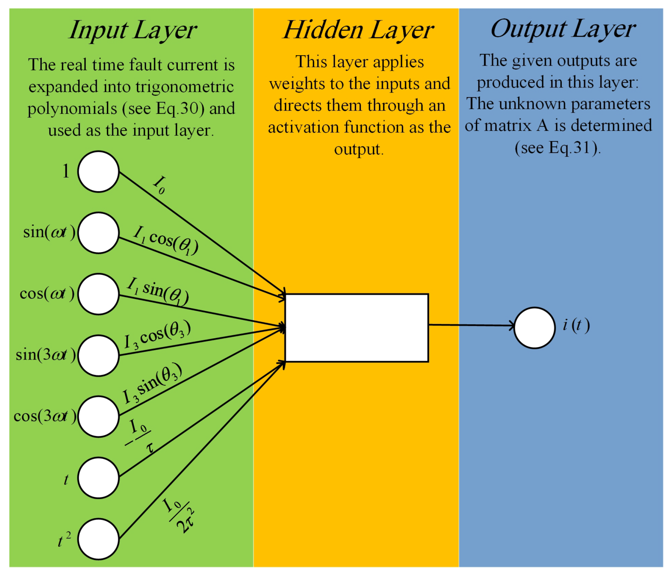
An artificial neural network (ANN) approach was developed for phasor estimation, which is applicable in numerical relays [49]. ANN is made of three layers, namely the input layer, output layer, and hidden layer(s). There must be a connection between the nodes in the input layer with the nodes in the hidden layer, and each hidden layer node with the nodes of the output layer. The input layer takes the data from the network [50].
Trigonometric functions that describe the FC waveform are expanded, encompassing the main, third, and fifth harmonics. In addition, the DDC parameter is approximated with the first term of Taylor series expansions. Then, an ANN structure is used with 12 neurons in the input layer, 1 neuron in the output layer, and 1 hidden layer with 1 neuron. The number of neurons on each layer was chosen in order to make the ANN reproduce. Figure 15 shows the overall ANN structure. The FC signal was expanded, such as LS-based methods in ANN methods; expanded functions consisted of the input layer. The DDC approximation can also be considered for sake of simplicity in the expanding step.
Similar to [49], ANN was used to find out the accurate phasor quantities for impedance estimation in distance relays, which used an online training method to quicken the process [51]. The ANN structure in this method is the same as in [49]; frequency deviation was investigated as well.
A deep neural network (DNN) was addressed to remove DDC from FC under harmonics and noise distortion [52]. TensorFlow library in Python is used to implement DNN for this purpose. Moreover, both intensive supervised/unsupervised training schemes were applied where the DNN size is indicated through autoencoders.
The eigensystem (ER) realization-based algorithm and Z-domain method are proposed to estimate both phasors and DDC in [53]. The ER algorithm uses discrete state space to model the FC. Markov parameters are estimated by a singular value decomposition using the LS method. In the Z-domain method, FC is written in the Z-domain and the poles of the denominator indicate the frequency. Once the frequency is obtained, phasors and DDC can be estimated. The ER algorithm needs a cycle of samples and the Z-domain-based method needs lees than a fifth of a cycle to recognize the phasor estimation.

6.2. Critical Review of Other Methods

Different methods are introduced in Section 6.1, which are not included in the past categories. In all of these methods, phasors and the DDC parameter are estimated together through heuristic methods. These methods are investigated based on the important factors listed in Table 5.
A three-step method is proposed in [46], including two filters and the Prony algorithm. The number of mathematical calculations is high, which increases the computational burden and cost of implementation. The linear filter and sine filter add an extra delay to the estimation process and ONF is not considered in this method. However, the error in the phasor estimation is lower than one percent.
In [47], solving an iterative equation obtains phasors as well as DDC parameters. This method presents a complicated approach, which needs at least three cycles of data and 0.05 s for computations. Since small TCs are less than 0.05 s, this method is not reliable in momentary faults. Moreover, as it is mentioned in [47], the computational burden increases when the convergent limit increases. Therefore, the accuracy of the method depends on the convergent limit and the sampling rate.
The SWT method is a frequency domain-based method, which is inherently sensitive to noise, while noise immunity is shown through different simulations [48]. Six layers with certain coefficients are determined for the phasor estimation, which increases the complexity and delay. This method is only able to distinguish DDC parameters less than 20 dB (regarding noise). Moreover, MDDCs and ONF are not considered in this method.
ANN and DNN have been investigated for phasor estimation [49,51,52]. These methods use a set of databases that are obtained through various data acquisitions, including simulation or real data. The accuracies of these methods are highly dependent on the volume of the dataset as well as diversity. Databases should be collected before any implementation of such methods, and because of that, a new database should be available for each case study. Therefore, ANN/DNN methods should have a fully online training procedure in the phasor estimation process, which is challenging in real studies. Moreover, DDC approximation, voltage, and current are considered for the fundamental phasor estimation, which decreases accuracy and increases complexity, respectively. Method [52] needs over 6400 simulations for the dataset preparation, which is time-consuming in the case of transient studies.
The ER method uses complex computations in its algorithms, which are not proper in real implementation. Furthermore, frequency deviations attenuate the Z-domain method, which is not considered. Moreover, the effect of noise and MDDCs are not taken into account for modeling/simulation.
Out of all the methods presented above, the Z-domain method in [53] was considered to be the most effective solution in phasor estimation in the presence of DDC. This method proposed a frequency domain analysis for phasor estimation, which attenuates DDC in a simple way using only six samples of FC. Although the Z-domain method is sensitive to frequency deviations and MDDCs, it suggests a more implementable solution, unlike others.
As stated in previous sections, a few heuristic methods are addressed to estimate phasors and DDC properly. The main advantages and drawbacks are as follows:
Advantages:
  • Precise and extensive data collection can easily increase the accuracy of the ANN and DNN methods.
  • DDC estimation can be taken into account in all conditions under the effects of all destructive factors in future attempts through ANN/DNN tools.
  • The frequency domain analysis opens up a new prospective in this field.
Drawbacks:
  • ANN and DNN need large training datasets for the phasor estimation in the presence of DDC and impose complexities on the overall system.
  • ANN and DNN are inherently offline methods, which need adaptive training data in the case of transient applications.
  • ANN and DNN methods depend on power system configurations for fault analysis.
  • Multiple filtering adds an extra delay to the phasor estimation.
  • Advanced mathematical approaches, such as the ER and Z-domain-based methods, impose large calculation loads on measurement/protection devices.

7. Future Scopes

As discussed in previous sections, plenty of methods have been proposed to tackle the DDC current in the phasor estimation. This section is dedicated to future scopes in DDC offset mitigation. As shown, pre-DFT methods are considered to be two or three samples in DDC parameter calculations, which endanger these methods against noise effects. Therefore, it is necessary to propose methods, such as the one presented in [3], which consider a set of samples for noise rejection or involve denoising the FC signal before any calculations by applying mathematical morphology [54]. Moreover, the CT effect should be investigated analytically in this category. For this aim, it is necessary to take MDDCs in problem modeling, such as LS-based methods. Moreover, plenty of signal processing methods are proposed, which could be suitable solutions for phasor estimation.
Post-DFT methods are more reliable due to the presence of the DFT process. DFT removes high-order harmonics as fast as possible. However, most of the post-DFT methods developed new schemes based on the recursive approach, which is time-consuming and highly sensitive to noise. Therefore, future works should focus on methods, such as, for example, the one presented in [11], to be more reliable in real applications.
The LS technique is a promising method in many cases, which is applied in the field of phasor estimations. DDC approximation is the most important challenge in LS-based methods. Therefore, the first attempt is to compensate for this drawback with simple solutions. Moreover, MDDCs and frequency deviation can be added to the LS mathematical model in future research projects. In addition, nonlinear Kalman filters were recently studied in the case of adaptive phasor estimation [55], which should be taken into account in further investigations.
The ANN is widely used in diverse applications and phasor estimations. However, a large data set and offline computations are the biggest challenges for applying this technique in transient applications. Developing adaptive/online training methods for protection studies is the most important subject in this field [56], which should be explored more. Moreover, DFT can be used as a powerful tool for decaying the complexity of ANN methods [57]. Furthermore, other hybrid methods based on past studies should be included [58].

8. Conclusions

This paper investigated DDC mitigation methods, which are introduced to maintain phasor estimation accuracy in measurement/protection systems. Four hypothetical groups, including DDC cancellation before DFT, DDC cancellation after DFT, DDC cancellation based on LS-based methods, and other heuristic methods, were discussed. Detailed investigations of the four groups were explained and the main advantages/disadvantages were addressed. Simulation results were provided for selected methods, which revealed the most efficient methods for DDC estimation. Guidelines to consider in future research were recommended. In this review paper, the following main findings were briefly explained:
  • Applying more complex mathematical approaches did not guarantee a higher efficiency of DDC estimation/elimination. (For instance: method [10] has the lowest RMSE among the simulated methods).
  • While the number of samples that were considered for DDC estimation should be minimized to reduce the delay, the noise effect should be taken into account as the main constraint.
  • The main drawback of conventional LS-based methods involves the approximation of the exponential term of the DDC. Recent studies attempted to solve this problem but the complexity increased.
  • The MDDC estimations were not addressed in the majority of past methods. Thus, it is necessary to include this issue through simplified mathematical solutions, such as pre-DFT methods.
  • The most challenging issue in the application of data-based methods involves online training. Therefore, future works in this category should propose a logical procedure to tackle this issue in a proper approach.
  • One could potentially investigate a wider range of pre-DFT methods due to their adaptions and ability to cover a broad range of mathematical solutions.

Author Contributions

Conceptualization, S.M. and A.M.; methodology, S.M.; validation, S.M.; investigation, S.M.; resources, S.M.; writing—original draft preparation, S.M.; writing—review and editing, A.M., A.Y., G.S. and S.K.; visualization, S.M. and A.M.; supervision, A.M. All authors have read and agreed to the published version of the manuscript.

Funding

This research received no external funding.

Institutional Review Board Statement

Not applicable.

Informed Consent Statement

Not applicable.

Data Availability Statement

Not applicable.

Conflicts of Interest

The authors declare no conflict of interest. The funders had no role in the design of the study; in the collection, analyses, or interpretation of data; in the writing of the manuscript, or in the decision to publish the results.

Nomenclature

i ( t ) fault current signal (continuous)
i [ n ] fault current signal (discrete)
I 0 DDC amplitude
τ DDC time constant
kharmonic order
I k kth harmonic of fault current
Tone cycle time period
θ k phase angle of kth harmonic
Nnumber of samples over a cycle
ω angular frequency
β phase angle of fundamental harmonic
Δ t time interval
Δ I D D C DFT of DDC signal
Wnoise signal
I d q 0 dq0 fault current signals
y [ n ] auxiliary signal
S1summation of current signal samples over a cycle
S2summation of auxiliary signal samples over a cycle
ϕ phase angle difference between voltage and current signals

References

  1. Jafarpisheh, B.; Madani, S.M.; Mohammad Shahrtash, S. A New DFT-Based Phasor Estimation Algorithm Using High-Frequency Modulation. IEEE Trans. Power Deliv. 2017, 32, 2416–2423. [Google Scholar] [CrossRef]
  2. Benmouyal, G. Removal of Dc-Offset in Current Waveforms Using Digital Mimic Filtering. IEEE Trans. Power Deliv. 1995, 10, 621–630. [Google Scholar] [CrossRef]
  3. Hajizadeh, H.; Ahmadi, S.A.; Sanaye-Pasand, M. An Analytical Fast Decaying DC Mitigation Method for Digital Relaying Applications. IEEE Trans. Power Deliv. 2021, 36, 3529–3537. [Google Scholar] [CrossRef]
  4. Musa, O.; Aksamovic, A. Comparative analysis of algorithms for elimination of exponentially decaying DC component. In Proceedings of the 2012 19th International Conference on Systems, Signals and Image Processing (IWSSIP), Vienna, Austria, 11–13 April 2012; pp. 362–367. [Google Scholar]
  5. Tajdinian, M.; Samet, H.; Hamedi, A.; Hadaeghi, A.; Bagheri, A.; Allahbakhshi, M.; Seifi, A. Enhancing Immunity of Full-Cycle Discrete Fourier Transform Against Decaying DC Components: A Comparative Analysis. In Proceedings of the 2019 IEEE International Conference on Environment and Electrical Engineering and 2019 IEEE Industrial and Commercial Power Systems Europe (EEEIC/I CPS Europe), Genova, Italy, 11–14 June 2019; pp. 1–6. [Google Scholar] [CrossRef]
  6. Jafarpisheh, B.; Madani, S.M.; Jafarpisheh, S. Improved DFT-Based phasor estimation algorithm using down-sampling. IEEE Trans. Power Deliv. 2018, 33, 3242–3245. [Google Scholar] [CrossRef]
  7. Schweitzer, E.O.; Hou, D. Filtering for protective relays. In Proceedings of the Communications, Computers and Power in the Modern Environment, Saskatoon, SK, Canada, 17–18 May 1993; pp. 15–23. [Google Scholar] [CrossRef]
  8. Kirpane, R.; Bedekar, P.P. Removal of DC offset using digital mimic filtering technique. In Proceedings of the 2016 International Conference on Global Trends in Signal Processing, Information Computing and Communication (ICGTSPICC), Jalgaon, India, 22–24 December 2016; pp. 470–475. [Google Scholar] [CrossRef]
  9. Soliman, S.A.; Alammari, R.A.; El-Hawary, M.E. A new digital transformation for harmonics and DC offset removal for the distance fault locator algorithm. Int. J. Electr. Power Energy Syst. 2004, 26, 389–395. [Google Scholar] [CrossRef]
  10. Phadke, A.; Hlibka, T.; Ibrahim, M. A digital computer system for EHV substations: Analysis and field tests. IEEE Trans. Power Appar. Syst. 1976, 95, 291–301. [Google Scholar] [CrossRef]
  11. Guo, Y.; Kezunovic, M.; Chen, D. Simplified algorithms for removal of the effect of exponentially decaying DC-offset on the Fourier algorithm. IEEE Trans. Power Deliv. 2003, 18, 711–717. [Google Scholar] [CrossRef]
  12. Cho, Y.S.; Lee, C.K.; Jang, G.; Lee, H.J. An innovative decaying DC component estimation algorithm for digital relaying. IEEE Trans. Power Deliv. 2009, 24, 73–78. [Google Scholar] [CrossRef]
  13. Abdoos, A.A.; Gholamian, S.A.; Farzinfar, M. Accurate and fast DC offset removal method for digital relaying schemes. IET Gener. Transm. Distrib. 2016, 10, 1769–1777. [Google Scholar] [CrossRef]
  14. Rubeena, R.; Zadeh, M.R.; Bains, T.P.S. An accurate offline phasor estimation for fault location in series-compensated lines. IEEE Trans. Power Deliv. 2014, 29, 876–883. [Google Scholar] [CrossRef]
  15. Bains, T.P.S.; Dadash Zadeh, M.R. Enhanced Phasor Estimation Technique for Fault Location in Series-Compensated Lines. IEEE Trans. Power Deliv. 2015, 30, 2058–2060. [Google Scholar] [CrossRef]
  16. Tajdinian, M.; Jahromi, M.Z.; Mohseni, K.; Kouhsari, S.M. An analytical approach for removal of decaying DC component considering frequency deviation. Electr. Power Syst. Res. 2016, 130, 208–219. [Google Scholar] [CrossRef]
  17. Pazoki, M. A New DC-Offset Removal Method for Distance-Relaying Application Using Intrinsic Time-Scale Decomposition. IEEE Trans. Power Deliv. 2018, 33, 971–980. [Google Scholar] [CrossRef]
  18. Kumar, B.R.; Kumar, A. Mitigation of the DC offset by a sub-cycle sample method M-Class PMUs. IEEE Trans. Power Deliv. 2019, 34, 1. [Google Scholar] [CrossRef]
  19. Kumar, B.R.; Mohapatra, A.; Chakrabarti, S. A Novel Sub-Cycle-Based Method for Estimation of Decaying DC Component and Fundamental Phasor. IEEE Trans. Instrum. Meas. 2021, 70, 1–10. [Google Scholar] [CrossRef]
  20. Afrandideh, S.; Haghjoo, F. A DFT-based phasor estimation method robust to primary and secondary decaying DC components. Electr. Power Syst. Res. 2022, 208, 107907. [Google Scholar] [CrossRef]
  21. Mohammadi, S.; Rezaei, N.; Mahmoudi, A. A novel analytical method for DC offset mitigation enhancing DFT phasor estimation. Electr. Power Syst. Res. 2022, 209, 108036. [Google Scholar] [CrossRef]
  22. Gu, J.C.; Yu, S.L. Removal of DC offset in current and voltage signals using a novel Fourier filter algorithm. IEEE Trans. Power Deliv. 2000, 15, 73–79. [Google Scholar] [CrossRef]
  23. Yu, S.L.; Gu, J.C. Removal of decaying DC in current and voltage signals using a modified fourier filter algorithm. IEEE Trans. Power Deliv. 2001, 16, 372–379. [Google Scholar] [CrossRef]
  24. Yang, J.Z.; Liu, C.W. Complete elimination of DC offset in current signals for relaying applications. In Proceedings of the 2000 IEEE Power Engineering Society Winter Meeting. Conference Proceedings (Cat. No.00CH37077), Singapore, 23–27 January 2000; pp. 1933–1938. [Google Scholar] [CrossRef]
  25. Rosołowski, E.; Izykowski, J.; Kasztenny, B. Adaptive measuring algorithm suppressing a decaying DC component for digital protective relays. Electr. Power Syst. Res. 2001, 60, 99–105. [Google Scholar] [CrossRef]
  26. Nam, S.R.; Park, J.Y.; Kang, S.H.; Kezunovic, M. Phasor estimation in the presence of DC offset and CT saturation. IEEE Trans. Power Deliv. 2009, 24, 1842–1849. [Google Scholar] [CrossRef]
  27. Gu, J.C.; Shen, K.Y.; Yu, S.L.; Yu, C.S. Removal of dc offset and subsynchronous resonance in current signals for series compensated transmission lines using a novel Fourier filter algorithm. Electr. Power Syst. Res. 2006, 76, 327–335. [Google Scholar] [CrossRef]
  28. Yu, C.S. A discrete Fourier transform-based adaptive mimic phasor estimator for distance relaying applications. IEEE Trans. Power Deliv. 2006, 21, 1836–1846. [Google Scholar] [CrossRef]
  29. Kang, S.H.; Lee, D.G.; Nam, S.R.; Crossley, P.A.; Kang, Y.C. Fourier transform-based modified phasor estimation method immune to the effect of the DC offsets. IEEE Trans. Power Deliv. 2009, 24, 1104–1111. [Google Scholar] [CrossRef]
  30. Rahmati, A.; Adhami, R. An accurate filtering technique to mitigate transient decaying DC offset. IEEE Trans. Power Deliv. 2014, 29, 966–968. [Google Scholar] [CrossRef]
  31. Lázaro, J.; Miñambres, J.F.; Zorrozua, M.A. Selective estimation of harmonic components in noisy electrical signals for protective relaying purposes. Int. J. Electr. Power Energy Syst. 2014, 56, 140–146. [Google Scholar] [CrossRef]
  32. Tajdinian, M.; Seifi, A.R.; Allahbakhshi, M. Half-cycle method for exponentially DC components elimination applicable in phasor estimation. IET Sci. Meas. Technol. 2017, 11, 1032–1042. [Google Scholar] [CrossRef]
  33. Hwang, J.K.; Song, C.K.; Jeong, M.G. DFT-Based phasor estimation for removal of the effect of multiple DC components. IEEE Trans. Power Deliv. 2018, 33, 2901–2909. [Google Scholar] [CrossRef]
  34. Kim, W.J.; Kang, S.H. A DC offset removal algorithm based on AR model. J. Int. Counc. Electr. Eng. 2018, 8, 156–162. [Google Scholar] [CrossRef]
  35. Honorato, T.R.; Silva, K.M. Half-Cycle DFT-Based Phasor Estimation Algorithm for Numerical Digital Relaying. In Proceedings of the 2018 Workshop on Communication Networks and Power Systems (WCNPS), Brasilia, Brazil, 7–9 November 2018; pp. 1–4. [Google Scholar] [CrossRef]
  36. Liang, Y.; Zhang, Z.; Li, H.; Ding, J.; Wang, G.; Chen, L. A robust and accurate discrete Fourier transform-based phasor estimation method for frequency domain fault location of power transmission lines. IET Gener. Transm. Distrib. 2022, 16, 1990–2002. [Google Scholar] [CrossRef]
  37. Sachdev, M.S.; Baribeau, M.A. A new algorithm for digital impedance relays. IEEE Trans. Power Appar. Syst. 1979, PAS-98, 2232–2240. [Google Scholar] [CrossRef]
  38. Girgis, A.A. A new kalman filtering based digital distance relay. IEEE Trans. Power Appar. Syst. 1982, PAS-101, 3471–3480. [Google Scholar] [CrossRef]
  39. Sachdev, M.S.; Nagpal, M. A recursive least error squares algorithm for power system relaying and measurement applications. IEEE Trans. Power Deliv. 1991, 6, 1008–1015. [Google Scholar] [CrossRef]
  40. Jafarian, P.; Sanaye-Pasand, M. An adaptive phasor estimation technique based on LES method using forgetting factor. In Proceedings of the 2009 IEEE Power and Energy Society General Meeting (PES ’09), Calgary, AB, Canada, 26–30 July 2009; pp. 1–8. [Google Scholar] [CrossRef]
  41. Jafarian, P.; Sanaye-Pasand, M. Weighted least error squares based variable window phasor estimator for distance relaying application. IET Gener. Transm. Distrib. 2011, 5, 298–306. [Google Scholar] [CrossRef]
  42. Hwang, J.K. Least error squared phasor estimation with identification of a decaying DC component. IET Gener. Transm. Distrib. 2018, 12, 1486–1492. [Google Scholar] [CrossRef]
  43. Min, K.W.; Santoso, S. DC offset removal algorithm for improving location estimates of momentary faults. IEEE Trans. Smart Grid 2018, 9, 5503–5511. [Google Scholar] [CrossRef]
  44. Achlerkar, P.D.; Panigrahi, B.K. Assessment of DC offset in fault current signal for accurate phasor estimation considering current transformer response. IET Sci. Meas. Technol. 2019, 13, 403–408. [Google Scholar] [CrossRef]
  45. Kim, W.J.; Nam, S.R.; Kang, S.H. Adaptive phasor estimation algorithm based on a least squares method. Energies 2019, 12, 1387. [Google Scholar] [CrossRef] [Green Version]
  46. Nam, S.R.; Kang, S.H.; Park, J.K. An analytic method for measuring accurate fundamental frequency components. IEEE Trans. Power Deliv. 2002, 17, 405–411. [Google Scholar] [CrossRef]
  47. Byeon, G.; Oh, S.; Jang, G. A new DC offset removal algorithm using an iterative method for real-time simulation. IEEE Trans. Power Deliv. 2011, 26, 2277–2286. [Google Scholar] [CrossRef]
  48. Yusuff, A.A.; Jimoh, A.A.; Munda, J.L. Stationary wavelet transform and single differentiator based decaying DC-offset filtering in post fault measurements. Meas. J. Int. Meas. Confed. 2014, 47, 919–928. [Google Scholar] [CrossRef]
  49. Da Silva, C.D.; Junior, G.C.; Mariotto, L.; Marchesan, G. Phasor estimation in power systems using a neural network with online training for numerical relays purposes. IET Sci. Meas. Technol. 2015, 9, 836–841. [Google Scholar] [CrossRef]
  50. Imran, M.; Alsuhaibani, S.A. A Neuro-Fuzzy Inference Model for Diabetic Retinopathy Classification. In Intelligent Data Analysis for Biomedical Applications; Elsevier: Amsterdam, The Netherlands, 2019; pp. 147–172. [Google Scholar] [CrossRef]
  51. Lana da Silva, C.D.; Cardoso, G.; de Morais, A.P.; Marchesan, G.; Kaehler Guarda, F.G. A continually online trained impedance estimation algorithm for transmission line distance protection tolerant to system frequency deviation. Electr. Power Syst. Res. 2017, 147, 73–80. [Google Scholar] [CrossRef]
  52. Kim, S.B.; Sok, V.; Kang, S.H.; Lee, N.H.; Nam, S.R. A study on deep neural network-based DC Offset removal for phase estimation in power systems. Energies 2019, 12, 1619. [Google Scholar] [CrossRef] [Green Version]
  53. Zamora-Mendez, A.; Sotelo-Castañón, J.; Arrieta Paternina, M.R.; Buendia, P.; Torres, C.; Toledo-Santos, C.; Velasco, V.; Zelayal-A, F.; Mejia-Ruiz, G.E. Two effective methods for impedance estimation in distance relays based on the DC offset removal. Electr. Power Syst. Res. 2021, 194, 107102. [Google Scholar] [CrossRef]
  54. Gautam, S.; Brahma, S.M. Overview of mathematical morphology in power systems—A tutorial approach. In Proceedings of the 2009 IEEE Power Energy Society General Meeting, Calgary, AB, Canada, 26–30 July 2009; pp. 1–7. [Google Scholar] [CrossRef]
  55. Khodaparast, J. A Review of Dynamic Phasor Estimation by Non-Linear Kalman Filters. IEEE Access 2022, 10, 11090–11109. [Google Scholar] [CrossRef]
  56. Rao, A.V.K.; Soni, K.M.; Sinha, S.K.; Nasiruddin, I. Dynamic phasor estimation using adaptive artificial neural network. Int. J. Syst. Assur. Eng. Manag. 2021, 12, 310–317. [Google Scholar] [CrossRef]
  57. Chitsaz, K.; Hajabdollahi, M.; Karimi, N.; Samavi, S.; Shirani, S. Acceleration of Convolutional Neural Network Using FFT-Based Split Convolutions. arXiv 2020, arXiv:2003.12621. [Google Scholar]
  58. Khodaparast, J.; Fosso, O.; Molinas, M. Phasor Estimation by EMD-Assisted Prony. IEEE Trans. Power Deliv. 2022. [Google Scholar] [CrossRef]
Figure 1. An equivalent circuit for fault analysis: switch K is closed for fault simulation.
Energies 15 05260 g001
Figure 2. Current signal before/after the fault occurs in the presence of DDC and the third harmonic.
Energies 15 05260 g002
Figure 3. Different Methods of DDC mitigation in the current phasor estimation process.
Energies 15 05260 g003
Figure 4. The overall statistics of the presented works (from 1976 to 2022) in terms of important parameters. (a) Summary of different articles in case of four destructive factors, which are included in an analytical approach or through simulation results. (b) The statistics of DDC mitigation methods in case of the required samples for accurate phasor estimation.
Energies 15 05260 g004
Figure 5. Amplitude of a typical FC signal with/without DDC.
Energies 15 05260 g005
Figure 6. General flowchart of DDC mitigation methods: pre-DFT, post-DFT, and LS-based methods.
Energies 15 05260 g006
Figure 7. Simulation results, method [7] (red line), under four different cases: (a) without noise, (b) in the presence of noise, (c) 0.5 Hz frequency deviation, (d) in the presence of the second DDC.
Energies 15 05260 g007
Figure 8. Mimic circuit for DDC elimination from the FC signal.
Energies 15 05260 g008
Figure 9. Simulation results, methods [10] (red line) and [11] (blue line), under four different cases: (a) without noise, (b) in the presence of noise, (c) 0.5 Hz frequency deviation, (d) in the presence of the second DDC.
Energies 15 05260 g009
Figure 10. Simulation results, methods [12] (red line) and [13] (blue line), under four different cases: (a) without noise, (b) in the presence of noise, (c) 0.5 Hz frequency deviation, (d) in the presence of the second DDC.
Energies 15 05260 g010aEnergies 15 05260 g010b
Figure 11. Simulation results, method [1,6] (red line), under four different cases: (a) without noise, (b) in the presence of noise, (c) 0.5 Hz frequency deviation, (d) in the presence of the second DDC.
Energies 15 05260 g011aEnergies 15 05260 g011b
Figure 12. Simulation results, method [18] (red line) and [3] (blue line), under four different cases: (a) without noise, (b) in the presence of noise, (c) 0.5 Hz frequency deviation,(d) in the presence of the second DDC.
Energies 15 05260 g012
Figure 13. Simulation results, method [22] (red line), under four different cases: (a) without noise, (b) in the presence of noise, (c) 0.5 Hz frequency deviation, (d) in the presence of the second DDC.
Energies 15 05260 g013
Figure 14. Simulation results, method [37] (red line), under four different cases: (a) without noise, (b) in the presence of noise, (c) 0.5 Hz frequency deviation, (d) in the presence of the second DDC.
Energies 15 05260 g014
Figure 15. ANN structure for phasor estimation: expanded trigonometric polynomials of the FC signal are considered for the input layer and fundamental phasor components and DDC was obtained as the output [51].
Energies 15 05260 g015
Table 1. Simulation parameters for the FC signal and DDC parameter.
ParameterDefinitionValue
ω Angular frequency 2 π ( 50 ) rad/s
I 0 DDC amplitude5 p.u
τ p Primary DDC time constant5 cycles
τ s Secondary DDC time constant0.4 s
I 1 Fundamental frequency amplitude1 p.u
θ 1 Fundamental frequency angle π / 6 rad
I 3 Third harmonic amplitude0.3 p.u
θ 3 Third harmonic angle π / 6 rad
Δ f Frequency deviation−0.5 Hz
WWhite noiseSNR = 4
Table 2. Pre-DFT DDC mitigation methods comparative analysis in the presence of destructive factors.
MethodNoiseHarmonicsOff-Nominal FrequencyMultiple DDCsSample Requirements
[10]xxx1 cycle
[7]xxx1+1/4 cycle
[2]xxxNA
[11]xxx1 cycle
[12]xx1 cycle +1 sample
[14]xx1 cycle
[13]xx1 cycle
[15]xx1 cycle
[16]x1 cycle +2 samples
[1]1 cycle
[17]x1 cycle +3 samples
[6]x1 cycle
[18]xx4 samples
[3]1/2 cycle +3 samples
[19]half cycle + 2 samples
[20]1 cycle
[21]half cycle + 1 sample
Table 3. Post-DFT DDC mitigation methods comparative analysis in the presence of destructive factors.
MethodNoiseHarmonicsOff-Nominal FrequencyMultiple DDCsSamples Requirement
[22]xxx1+1/4 cycle
[24]xxxNA
[23]xx1 cycle
[25]xx1 cycle +1 sample
[27]xxx1 cycle
[26]xxx1 cycle +2 samples
[29]x1 cycle
[30]xx1 cycle +3 samples
[31]x1 cycle
[32]1 cycle
[33]x1 cycle
[35]xxx1/2 cycle +3 samples
[34]xxx1/2 cycle +3 samples
[36]≥ 1 cycle
Table 4. LS-based methods—a comparative analysis in the presence of destructive factors.
MethodNoiseHarmonicsOff-Nominal FrequencyMultiple DDCsSample Requirements
[37]xxx7 samples
[38]xx1 cycle
[39]xxx20 samples
[40]xxx1 cycle
[41]xxx1 cycle
[42]7/8 cycle
[43]xxx1 cycle
[44]xx8 samples
[45]x1 cycle
Table 5. Other methods—comparative analysis in the presence of destructive factors.
MethodNoiseHarmonicsOff-Nominal FrequencyMultiple DDCsSample Requirements
[46]xxx1 cycle + 2 samples
[47]xxxx7 samples
[48]xx1 cycle
[49]xxx20 samples
[51]x1 cycle
[52]xx1 cycle
[53]xxx7/8 cycle
Publisher’s Note: MDPI stays neutral with regard to jurisdictional claims in published maps and institutional affiliations.