Article

A Numerical Study on the Energization of the Field Coils of a Full-Size Wind Turbine with Different Types of Flux Pumps

Department of Electrical, Electronic and Information Engineering, University of Bologna, 40135 Bologna, Italy
*
Author to whom correspondence should be addressed.
Energies 2022, 15(15), 5392; https://doi.org/10.3390/en15155392
Submission received: 24 June 2022 / Revised: 18 July 2022 / Accepted: 24 July 2022 / Published: 26 July 2022
(This article belongs to the Special Issue Electrical Machine Design 2021)

Abstract

:
High temperature superconductivity is emerging as a solution for lightweight, cost-effective and high-power wind generators. Current injection and maintainment/sustainment in the field winding are obtained by metal current leads which, due to persistent heat conduction and joule loss, are responsible for a large part of the total cryogenic heat load. Slip rings, which further reduce the overall performance and reliability of the system, are also required. In this paper we assess the viability of the HTS dynamo and the rectifier flux pumps for energizing the field coils of the EcoSwing 3.6 MW HTS wind generator. Both a “warm” solution, with the rectifier at room temperature, and a “cold” solution, in which the latter is integrated into the cryostat, are investigated with regard to the rectifier flux pump. A comparison with the actual, state-of-the-art, system of the EcoSwing machine is carried out in terms of the total required cooling power and the ability to charge the HTS field winding up to the rated current. It is found that the dynamo flux pump, beside avoiding the need of slip rings, allows the reduction in the required cooling by about 74% with respect to the conventional current-leads-based solution.

1. Introduction

High magnetic field and low weight make high temperature superconducting (HTS) magnets a promising solution for power-dense lightweight electrical devices [1,2,3]. Due to increasing interest in this field [4], the feasibility of HTS machines has been under investigation through several demonstrators [5,6,7,8,9,10]. Wind generators, with particular regard to offshore turbines, can take substantial advantages from the possibility of using HTS magnets as field coils since they replace heavy and expensive permanent magnets in the rotor allowing higher field strengths, and resulting in lightweight, cost-effective power generation machines. Moreover, given the fact that HTS materials require a very small percentage of rare earth [11], much less than what is needed for conventional permanent magnets, their advent could further contribute to the industrial viability of electrical motors. Different from low temperature superconductors (LTS), HTS suffer greater current and field decay due to non-negligible flux creep, more resistive joints and AC-field-induced losses [12,13]. Therefore, a power supply is needed for maintaining persistent currents in HTS coil magnets, independently from the application they are aimed at. The common way of energizing HTS magnets is using bulky and expensive current leads. These are resistive-metal feedthroughs connecting the cold HTS coil to the room temperature supply and are a major source of heat invasion due to both heat conduction and resistive loss. Furthermore, supplying power via current leads in rotating machines requires the use of brushes and slip rings which further increase the overall cost and reduce the reliability of the whole system. Flux pumps have recently emerged as a low cost, contactless and compact alternative to the use of current leads [14,15,16,17]. Several laboratory demonstrators [18,19,20,21,22,23,24] have been realized for proofing the concept and intense numerical modeling has been developed for understanding the underlying physics and driving the optimization [25,26,27,28,29,30,31,32,33]. Nevertheless, only a few studies have focused on assessing the technical advantages that flux pumps could provide for real power applications [34,35,36,37,38]. The purpose of this work is to contribute to reducing this gap by assessing the viability of the flux pump technology for a full-scale wind generator. In particular, the paper addresses the technological challenge of energizing the HTS field coils of the EcoSwing wind generator, the world’s first HTS wind turbine [5,39,40,41,42], with two different types of flux pumps, namely a dynamo flux pump and an electronic-switches-based rectifier flux pump [15,43]. By doing so, this study is the first to provide a performance comparison between the actual power supply system and the current most-investigated types of flux pump for the case of a full scale, operating HTS machine. With such a comparison, this works aims at identifying both the potential advantages and challenges of each type of flux pump for energizing superconducting electrical machines, as well as pointing out the future development needed for practical applications. Both the considered flux pumps are designed in detail and their performance is numerically assessed and compared in detail with the state-of-the-art solution used for the EcoSwing machine, consisting of the combination of power electronics power supply, slip rings and current leads. As for the rectifier-type flux pump, two different layouts, involving a “warm” (room-temperature) AC voltage source and a “cold” AC voltage source integrated into the cryogenic environment, are considered. Hence, three different flux pumps designs are investigated and compared in total, in order to give a comprehensive guideline toward the development of effective and viable flux pumps, with no bias concerning the topology to be chosen. In fact, although excellent reviews have been delivered in the past [14,15,16] and design works have been carried out with reference to specific topologies, to date, neither a quantitative comparison of different kinds of flux pump nor any study involving a rectifier type operating on a real electrical machine has been produced to the knowledge of the authors. This comparison is carried out in terms of the total required cooling power and ability to charge the HTS field winding of a practical machine up to the rated current.
This paper is structured as follows. In Section 2, the EcoSwing wind turbine is described, with particular focus on the rotor coils power supply, the heat load due to current leads, and the HTS field winding. In Section 3, the concepts of dynamo and rectifier flux pumps are briefly resumed, and the details of the designed devices are discussed. In Section 4 the results of the comparison are reported, showing that flux pumps, and the dynamo type flux pump in particular, are a very promising alternative to conventional power supply systems based on current leads and slip rings. Finally, Section 5 summarizes the conclusions of this study.

2. The EcoSwing Field Winding System

The EcoSwing wind turbine is the milestone result of an EU H2020 project carried out by a consortium of nine partners from industry and academia and concluded in 2019 [44]. A full-scale 3.6 MW direct drive (DD) HTS generator was designed, developed, installed and operated in an existing wind turbine [5]. The generator consists of a 20-pole-pairs rotor made of HTS field winding and a conventional stator. The detailed specifics can be found in [40]. A 24% overall weight reduction and 26% size reduction, with respect to the conventional counterpart used for the same wind turbine, were achieved.
The system performed stable operation at 2 MW and was boosted to 3 MW as well. Overall, the generator delivered 600 MWh to the grid over a continuous operation period of more than 650 h, proving on field the technological feasibility of HTS wind turbines and improving its TRL from 4–5 to 6–7 [40].
The HTS field winding consists of 40 racetrack-shaped HTS coils [42] located inside a self-sustaining vacuum insulation that are cooled at an operating temperature lower than 30 K [45] by nine rotating compressor-driven cold heads (Sumitomo F70). The iron poles of the rotor are integrated into the cryostat and operate at cryogenic temperature as the windings. The cold heads are mounted onto the rotor and are fed for their operation with high-pressure gas helium by means of nine stationary compressors using a rotating joint [5] THEVA provided the high-performance 2G HTS conductor (ReBCO TPL 2100) used in the field magnets. Detailed specifications about the tape and the coils can be found in [5,46]. The schematic of the rotor’s electrical circuit is shown in Figure 1. The power supply system of the HTS field winding involves a voltage source, a dump resistor, a freewheeling diode and an insulated gate bipolar transistor (IGBT) [41]. More details on the rotary joint assembly, comprising the coupling joint of the stationary and rotating gas helium pipes system and the slip rings and brushes providing electrical connection between the power supply and field winding are given in [42].
The main characteristics of the HTS field winding system are reported in Table 1. The critical current of the HTS magnet depends both on the magnitude and the orientation of the magnetic acting on the conductor [5,47,48,49]. Overall, the HTS field winding of the EcoSwing requires about 35 kW cooling power (at room temperature) to maintain the operating temperature of the coils at 30 K [40]. Different contributions are responsible for this amount of power: HTS magnets’ AC loss, thermal radiation, thermal income from the current leads and additional loss. Among those, the coils’ AC loss and the thermal radiation do not change according to which power supply is employed, therefore they are not taken into account in this comparison. A pair of hybrid Cu/HTS current leads are used to connect the HTS field winding to the power supply. The leads consist of a copper feedthrough bar with one end connected to the power supply and the other end anchored at an operating temperature of 60 K inside the cryostat, by means of a dedicated cryocooler (which is also used for anchoring the temperature of the radiation shield) [5]. An assembly of HTS tapes in parallel (HTS stage of the lead) is used, inside the cryostat, for connecting the 60 K end of the Cu bar to the input terminal of the HTS field winding, that is maintained at 30 K by means of eight dedicated cryocoolers. Based on common engineering experience, a heat load of 50 W/kA at 60 K can be assumed for each of the current leads [50,51,52]. By considering the rated current of the EcoSwing rotor ( I n = 0.330 kA), the total (for both the leads) heat invasion P c l c r y o at cryogenic temperature due to current leads is found to be 33 W for the considered supply system. A coefficient of performance (the ratio between the power to be supplied at ambient temperature to the cooling system and the thermal power extracted for the cryogenic environment and transferred to the ambient) COP = 22 W/W is assumed, based on the typical performance of conventional cryocooler performances operating between 300 K [53] and the operating temperature of 60 K of the current leads. Hence, the input power P c l a m b of the cooling system at ambient temperature is calculated as
P c l a m b = P c l c r y o ×   COP
According to (1), an input power of 726 W is obtained for the cooling system for retaining the current leads at the required temperature. The circuit model of the winding is the fundamental input needed for carrying out the design of the flux pumps and therefore it is discussed here. Overall, the field winding corresponds to the non-linear two-terminal RL component shown in Figure 2. The constant resistance Rload accounts for the losses in all the electrical connections (joints) between the different modules of the field winding as well as the electrical joint between different sections on one module, while the non-linear inductance Lload represents the overall terminal inductance of the winding. The inductance is non-linear due to the iron poles that reaches saturation at the nominal current of the winding. Neglecting the dependance of the inductance on the current would not be acceptable for the proper design of the flux pumps supply.
An inductance Lload = 10 H at rated rotor current I n is considered [54]. This corresponds to a total flux fi = 3330 Wb linked by the winding. For obtaining the L-I curve, the whole fi-curve was deduced as a first approximation from the B0-i curve reported in [5], where B0 is the measured field at the center of one coil. The LI curve of the rotor winding, in the current range from 0 to 330 A, was finally obtained by taking the numerical derivative of the fi-I curve and is shown in Figure 3. As for the resistance R l o a d , we report that each of the HTS coils of the rotor winding has up to 10 lap joints, with an interface resistance of 36 ± 9 nΩcm−2, and a 5 cm overlap. Furthermore, all adjacent coils are connected in anti-series with a hybrid copper-HTS design connection with an average resistance of 32 nΩ at 77 K. By considering all the intra- and the inter-coil joints, a total resistance R l o a d of 4.13 µΩ is found for the field winding. No further resistance exists in the model of the winding since the coil current is below the critical current of the superconductor at the chosen operating temperature and magnetic field. Possible additional resistance may arise during normal operation of the generator due to AC field ripple on the field windings [55,56], but this is not considered in the present study. In the next sections, the L vs. I curve and the total joints resistance R l o a d are used in the equivalent circuits of the systems for simulating the energization of the field coils for all the cases of dynamo and rectifier flux pumps as power supplies.

3. Design and Characteristics of the Flux Pump Power Supply Systems

In this section the three different systems considered for the power supply; the dynamo flux pump, the cold rectifier flux pump and the warm rectifier flux pump, are designed and described.

3.1. Dynamo Flux Pump

Superconducting dynamos consist of one or more rotating permanent magnets that cyclically move across a HTS tape in order to induce an average DC output voltage across its ends. Although the physical mechanism of dynamos is not intuitive and still under debate, several experimental tests have proven that such an apparatus is able to energize a superconducting coil [18,22,57].
In Figure 4, a 3D schematic of the designed dynamo flux pump is shown. The schematic of the overall contactless power supply system of the HTS field winding is shown in Figure 5. The dynamo consists of three THEVA Pro-Line 2G HTS with 12 mm width exposed to the field produced by 20 permanent magnets. The main characteristics are reported in Table 2. The HTS tapes are fixed with respect to the HTS field winding and move with the generator’s rotor. The magnets are mounted on a separate, and free to rotate, assembly, and their rotational velocity ω P M   in the stationary frame can be controlled independently from the rotational velocity ω m   of the generator’s rotor (see Figure 4 and Figure 5). The three HTS tapes are connected in parallel and each carries one-third of the overall current supplied to the load winding. Two collector rings (highlighted with − and + signs in Figure 4) connected to the opposite ends of the tapes form the terminals of the flux pump to which the load is connected. The layout shown was arrived at by means of optimized design. In particular, as it is discussed next, the presented solution is the one that allows to obtain the maximum output power and efficiency when it operates in the vicinity of the rated current I n = 330 A. The relevant parameters of the flux pump are summarized in Table 2.
The permanent magnets (PMs) rotate with respect to the tapes with a relative angular velocity ωr given by
ω r = ω P M ω m
The relative motion produces the desired voltage rectification at the terminals and current injection in the load, thus realizing a contactless power transfer from the flux pump rotor and the HTS winding of the generator. It was found during the design phase of the flux pump that a relative rotational velocity ωr = 1500 rpm between PMs and tapes is needed for producing the required voltage (see Table 2). By considering the rated speed ω m = 15 rpm of the generator’s rotor [40] (See Table 1), an angular velocity ω P M = 1485   rpm   needs to be applied to the permanent magnets. The performance of dynamo flux pumps increases with the magnetic field acting on the HTS tape and a short distance from the permanent magnets is desirable. An air gap of 5 mm between the PMs and the HTS tapes is chosen in this paper, as reported in Table 2. This airgap is feasible by means of an optimized design of the section of the cryostat hosting the flux pump (and in particular of the vacuum system) which can be independent from, though it can be conveniently integrated with, the main cryostat of the HTS rotor winding. It is also reported that novel dynamo configurations have been recently investigated that allow a substantial increase in the B field on the tape even in the presence of larger air gaps by including back iron in the magnetic circuit [19,35,58]. Hence, the dynamo used in this work can be considered as a conservative design that can be further improved in the future by means of innovative solutions. It is also noted that the operating temperature of the dynamo’s tapes (77 K) differs from that of the EcoSwing field winding’s. Such an operating condition can be obtained by means of a specific cold head dedicated to the cooling of the flux pump. Since one cryocooler has been specifically dedicated to currents leads in the EcoSwing machine, no additional cooling devices are required. On the other hand, a cheaper cryocooler with lower cooling capacity could be used instead.
The modelling approach recently proposed in [59] has been used for designing and characterizing the dynamo of Figure 4. Differently than in [59] the dependance of the critical current density of the HTS tapes on the amplitude B and the direction θ of the magnetic field is taken into account in this paper. This corresponds to a more realistic assumption and, as reported in the literature [22,25,28,30,60], significantly improves the performance and efficiency of the flux pump. The J c ( B , θ ) curve used has been interpolated, by using the approach presented in [61], from the experimental characterization data of the considered tape, available in the public Robinson Research Institute HTS database [62,63,64].
The V-I characteristic of the dynamo, as well as its performance in terms of losses and efficiency over a wide range of transport current are shown in Figure 6. The data were obtained by means of the FEM model [59] and are in very good agreement with experimental results of similar apparatuses [60,65]. The value I0 = 658 A fixes the limit beyond which the flux pump is not able to operate as a generator. In fact, as far as the transport current is in the range from 0 to I0 = 658 A, a positive voltage is developed at the terminals and, hence, power is delivered (in average in one period) by the flux pump to the load. If the transport current exceeds the value I0, then the voltage reverses and the power is absorbed by the flux pump. The output power at the terminal also changes approximately quadratically with the output current. It is zero in no load conditions and at the boundary I0 of the generator region, and reaches a maximum of the 19.8 W when the transport current approaches I l o a d = 400 A. The dynamo dissipates at about 300 W in no-load condition at zero transport current (that is, when the PMs are rotating while no load is connected to its terminals). The losses follow a quadratically like trend with the transport current as well. As a result, the efficiency of the device, defined as the ratio between the output power at the terminals and the mechanical power supplied by the rotor, is maximum at I l o a d = 350 A where it reaches the value of 5.78%, and is equal to 5.74% at I l o a d = 330 A, namely, the rated current of the field winding. We highlight that the deviation from a perfect quadratic trend of the losses and the output power is to be found in the slight nonlinearity of the V-I of the dynamo. It is also pointed out that changing the number of tapes and/or permanent magnets, as well as the other geometrical parameters, changes the performance of the flux pump. The solution and geometrical parameters reported in Table 2 were obtained empirically with the aim of maximizing the power output and the efficiency at the rated current. It must be specified that setting the relative angular speed of the PMs and the tapes equal to zero cancels the voltage at the terminals. As a result, no power is supplied nor absorbed (as mechanical power at the rotor) by the flux pump in this condition and the HTS tape forms a short circuit connection at the terminals of the HTS field winding. It will be shown in the Section 4 that optimal overall efficiency of the supply system based on the dynamo flux pump is obtained by periodically switching from this operating condition, that is defined as “off-state”, to the “on-state” one in which the PMs rotate at the nominal speed, as was previously suggested in [35].
The equivalent circuit of the dynamo flux pump that has been obtained from finite element analysis by using the approach of [59] is shown in Figure 7. This improved equivalent circuit is able to account for the overall loss of the device at cryogenic temperature. Coincident results concerning the current profile of the HTS field winding supplied by the flux pump are obtained if the full FEM model or the equivalent circuit of Figure 7 are used [59]. However, the calculation time needed by using the equivalent circuit is much shorter, therefore, this circuit is exploited for investigating the charging process of the HTS field winding in this paper. This equivalent circuit, whose parameters are reported in Table 3, takes into account all the losses that occur during the dynamo operation. In particular, R i n s t r i n s i c addresses the open-circuit losses which also take place during charging state, whereas R e f f e c t i v e accounts for the transport current losses. V 0 is average no-load voltage that is computed at the ends of each tape over a rotating cycle of the dynamo. It must be noted that the instantaneous open-circuit voltage produced by the flux pump could have been used instead of V 0 for reproducing the ripple of the load current [59]. However, this ripple only has a small amplitude and does not impact the overall conclusion, therefore it has been neglected in the present study.

3.2. “Cold Rectifier” Flux Pump

The rectifier type flux pump consists of a contactless (inductive) AC voltage source and at least two switches (acting like diodes) connected to a load coil [14]. The rectifier flux pump is different from the conventional rectifier because either the load coil or the whole circuit is superconducting. Starting from the AC voltage source, a half-wave rectified voltage is created at the terminals of the load by means of the diodes. For stationary systems, the AC voltage is usually obtained by means of a transformer. In this paper we assume that AC voltage is produced by a dedicated superconducting winding fixed with the rotor and exposed to the field produced by a set of stationary electromagnets, similar to conventional brushless exciter solutions [66]. A system of permanent magnets, as for the dynamo flux pump in Figure 5, can be also considered instead of the electromagnets. We also assume that both the HTS AC winding and the diodes are integrated in the cooling system and operate at cryogenic temperature. This solution, which is schematically represented in Figure 8, allows avoiding both slip rings and current leads, thus improving reliability and setting P c l a m b to zero. However, the losses of the rectifier diodes take place at cryogenic temperature, therefore the same COP used in equation must be applied for computing the required power.
Improved performances can be achieved by replacing the diodes with lossless (or very low loss) superconducting switches. Although promising results were recently achieved in manufacturing superconducting switches by exploiting flux-flow resistance of HTS tapes [67,68,69], a viable solution with sufficient off-state resistance is yet to be developed and is not considered here. It is assumed in the following analysis that the temperature does not affect the electrical behavior of the diodes. This can be considered a conservative assumption since recent studies indicated that power electronics components able to operate at cryogenics temperatures with improved performance are now becoming available [70,71]. A MATLAB-Simulink model was implemented for evaluating the performance of the flux pump. The schematic half-wave rectifier flux pump model connected to the EcoSwing HTS field winding is shown in Figure 9. We have implicitly assumed that the dissipation occurring in the superconducting AC voltage source is small compared with the overall dissipation of the diodes, hence no resistance appears in the equivalent circuit model of this source in Figure 9. The parameters of the model are listed in Table 4. The voltage and the frequency of the AC source were obtained by means of an empirical procedure (trial and error) supported by the analytical analysis of the circuit. The selected frequency (13 Hz, which is typical for this type of systems [24]) can be obtained by means of a rotating PM system with controlled relative velocity similar to the one considered for the dynamo-type flux pump. The self-inductance of the AC voltage source is assumed to be 1 mH. This value was obtained from the inductance data of a commercial transformer of similar voltage and power rating.

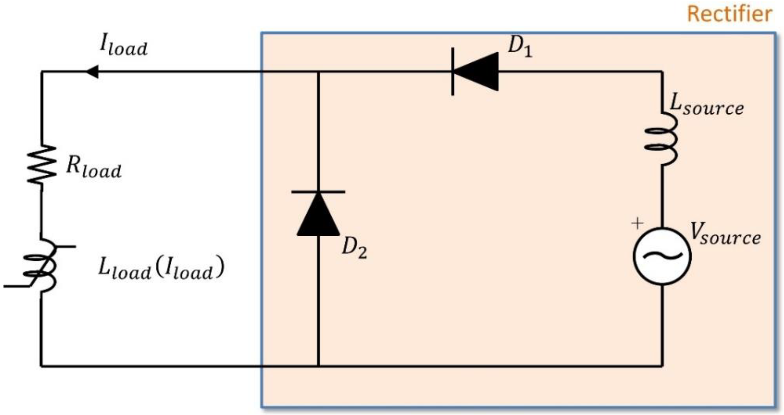
3.3. “Warm Rectifier” Flux Pump

In the “warm rectifier”-type flux pump, both the AC winding and the rectifier operate at room temperature outside the cryostat, hence they both conduct normally, whereas the HTS field winding is reached by means of current leads as for the conventional solution. The schematic of such configuration is shown in Figure 10. The same equivalent circuit of Figure 9 can be used for modelling this system. Similar to the “cold rectifier”, we assume that the loss occurring in the AC winding is negligible compared to the loss of the diodes. No COP is to be considered for the computation of the power that the source must provide. However, this solution still requires current leads, and the corresponding cooling power P c l a m b must be taken into account in the energy balance. Slip rings could still be avoided, thus increasing the reliability of the device.

4. Results and Discussion

The results of the energization of the HTS field winding by means of the dynamo flux pump are discussed first. In DC condition the inductance L l o a d produce no effect and the HTS rotor winding is equivalent to the sole resistance R l o a d . Hence, when the dynamo flux pump is considered, a final current of 658 A (corresponding to V 0 / ( R e f f e c t i v e + R l o a d ) ) would be reached, according to the equivalent circuit in Figure 7, in the HTS field winding. Thus, in order to achieve steady DC operation at the rated current of I n = 330 A, a closed loop hysteresis control has been implemented by switching the flux pump from the on- and the off-mode with rated duty cycle. In particular, during the first charge of the field winding, the flux pump is continuously in the “on-state”, meaning that the PMs of the rotor rotate with the rated relative velocity of 1500 rpm (see Figure 4), with respect to the tapes, and the current injection takes place according to the circuit of Figure 7. In this condition a voltage V 0 = 99.4 mV is produced by the flux pump causing the increase in the current of the coil following the profile shown in Figure 11. As the transport current exceeds I n by a threshold of +0.2%, flux pumping is stopped by changing the angular velocity of the PMs so that they move synchronously to the tapes. In this condition, referred to as “off-state”, no voltage is produced at the terminals and the tapes of the dynamo flux pump naturally offers a negligible resistance path for the circulation of the DC HTS field winding current. It is stressed that no dissipation occur in the flux pump in the off-state since no transient current, needed instead in the on-state for producing the rectified voltage [59], is induced. However, due to R l o a d , this current undergoes a slow decay with a time constant of L c o i l ( I l o a d ) / R l o a d . Due to this decay, as soon as, a current 0.2% lower than I n is reached, the on-state is restored. As a result, after the first charging, the current reaches a cyclic steady state in which it oscillates around the nominal value I n = 330 A with a ±0.2% ripple. This is abundantly lower than 1%, therefore it is assumed that the AC loss in the coils due to current ripple is neglectable compared to the other loss contributors, hence it is not taken into account in the total loss evaluation.
The rated current I n is reached by the dynamo during the ramp-up phase after about 12 h (43,805 s). After this phase the current is kept between 330.66 and 329.34 A by the controller that switches the dynamo between the on and the off- state, as it is displayed in Figure 11. It is noted that such a long charging time may represent a drawback for the practical commissioning of the turbine. However, if needed, this drawback can be overcome by designing a dynamo with a higher output voltage. As an example, a dynamo with an output voltage of 500 mV voltage (against 99.4 mV of the one considered in this study) would allow a charging-time reduction down to 2 h and could meet the requirement of a shorter energization time if required. On-states (with relative rotation at rated velocity between PM and tapes) and off-states (with no relative rotation) alternate over a cycle lasting 95 min (5695 s). The on-state only occurs for 157 s, corresponding to a duty cycle of 2.76%. The power dissipated by the flux pump during the process is shown in Figure 12. It can be noted that loss occurs in the flux pump as soon as the rotation and the charging of the HTS field coil begins. During the charging, the loss slightly increases with the load current. A heat load P d y n a m o   ( o n ) c r y o = 315.5 W is produced when the flux pump is in the on-state and the nominal current is reached. However, once the charging is complete, the current of the load remains practically constant and the flux pump alternates between the on- and the off-state, with loss only occurring in the on-state occupying 2.76% of the cycle.
The average dissipation at cryogenic temperature of the dynamo flux pump during the cyclic operation at nominal current can be computed as follows:
P d y n a m o   ( a v e r a g e ) c r y o = P o n c r y o × δ
where δ is the duty cycle, resulting in 8.7 W. This value must be compared with a heat load of 33 W reached with the current leads. It is stressed that, despite the much lower average value, a substantial dissipation (315.5 W) is produced during the ramp-up. Thus, appropriate sizing of the dedicated cooling apparatus must be considered for preventing excessive temperature of the HTS field winding during the charging process.
Finally, the input power needed at ambient temperature for cooling the flux pump is obtained by taking the COP into account as in (3) and gives P d y n a m o   ( a v e r a g e ) a m b = 191 W. Since a cooling power P c l a m b = 726 W was obtained in Section 2 for the conventional, current-leads-based supply system, a drastic reduction (74%) of the cooling cost for energizing the HTS field winding of a 3.6 MW wind turbine is achieved with the flux pump. Moreover, it should be noted that flux pumps are contactless power transfer devices requiring no slip rings, which means that reliability is improved, and complexity reduced by avoiding electrical rotary coupling and simplifying thermal coupling. Such an overall improvement decreases both the investment and the operating and maintenance costs of the system, resulting in a reduced levelized cost of energy.
The purpose of this study is to compare different energization systems of the field winding of a full-scale wind turbine in terms of total equivalent heat load. However, compatibility of the considered solutions with fast de-energization of the coil in case of failure of the system must be considered. As for the dynamo flux pump, a resistor with a normally closed switch in parallel can be included in the superconducting loop of Figure 5. Both the switch and the resistor operate at cryogenic temperature. When the discharge is needed, the switch is open and the current flows in the resistor discharging the coil. Research is in progress for developing quench protection systems fully integrated inside the cryogenic environment, delivering promising results [72]. Both mechanical and solid-state solutions can be considered for the switch. Whereas using a mechanical switch would not impact very much on the behavior of the system, additional losses would be added by the static solid-state switch requiring a higher output voltage of the flux pump. However, several experimental studies have reported substantial improvement of performance of electronic switches at cryogenic temperature, including reduction in forward voltage drop and switching performance [73,74], thus making their adoption viable. The design of the protection system of the HTS rotor coil supplied by the flux pump will be the subject of a future work.
Next, the results of the transformer rectifier flux pumps are reported. The results apply for both the cold- and the warm- transformer rectifier flux pump because it is assumed that the thermal problem does not substantially affect the electromagnetic one. This is to say that the equivalent resistance and dissipation of the diodes is little affected by the operating temperature. Figure 13 shows the energization transient of the field winding obtained with the Simulink model of Figure 9.
The load current reaches the rated value I n in about 2500 s, hence much faster than for the dynamo case, oscillating according to a 0.02% ripple which is not highlighted in Figure 13. It is noted that such ripple is even smaller than the dynamo’s, therefore the corresponding AC loss is negligible too. No control is implemented in this case since the rectifier is designed to have a steady state current of I n if coupled with the circuit of Figure 2.
The total power dissipated in the transformer rectifier flux pump during steady state is shown in Figure 14. The rectifier dissipates P a v e = 355.5 W in average when I n is reached, ranging from a minimum of 321 W to a maximum of 380 W.
The total cooling power of the “warm rectifier” flux pump is the sum of the average power dissipated by the rectifier ( P a v e = 355.5 W) and cooling power current leads ( P c l a m b = 736 W), which gives P wr a m b = 1081.5 W. The increase in power of the contactless warm rectifier flux pump, with respect to the conventional solution, only corresponds to 1% of the total power required at ambient temperature (35 kW) but produces the very substantial advantage of simplifying the rotary joint by avoiding the slip rings. However, it is acknowledged that a real device should also include a quench protection system. Similar considerations to the ones previously discussed for the HTS dynamo can be made by including a discharge resistor with a switch in parallel to a in the electrical loops of Figure 8 and Figure 10.
The cooling power of the cold rectifier must be computed by accounting for the cooling cost due to having rectifier loss ( P a v e = 355.5 W) occurring at cryogenic temperature and, assuming the same COP of 22 for the conventional and dynamo supply systems, gives P cr amb = 7821 W.
Although a “cold rectifier” allows the technical advantage of avoiding both current leads and slip rings, since the rectifier loss P cr amb is substantially larger that P c l a m b , this solution is noncompetitive in terms of efficiency. It is noted, however, that a power loss worst-case scenario has been considered in this study by using a diode-based half-wave bridge rectifier flux pump. It should be considered that fully superconducting transformer rectifiers are being investigated and recent studies are reporting promising results at the early stage [23,24,67,68,69]. Since most of the losses of the cold rectifier take place in the diodes, this study confirms that if progress in high-performance superconducting rectifier bridges is accomplished, rectifier flux pumps are indeed a very promising solution for energizing HTS magnets by drastically reducing the heat load [75]. Finally, Table 5 sums up the energetic comparison between the power supply types considered for this study and reports their main technical differences.

5. Conclusions

In this paper, we have numerically assessed the viability of energizing the HTS field winding of a full-scale wind generator with flux pump technology. Two different flux pump types, the dynamo flux pump and the rectifier flux pump, have been considered for injecting and maintaining the rated current in the HTS field coils of the 3.6 MW EcoSwing wind generator. As for the rectifier flux pump, both the “warm” solution, with the transformer and the rectified at room temperature, and the “cold” solution, in which the latter are integrated into the cryogenic environment, have been investigated. The performance of the flux pumps has been evaluated in terms of total cooling power required and ability to charge the HTS field winding up to the rated current. The results have been compared with the state-of-the-art power supply of the wind turbine, which involves current leads and slip rings. It was found that the cooling power required by the dynamo flux is 26% (191 W vs. 726 W) of the cooling power required for the current leads. Due to the contactless operation no slip rings are needed. These results agree with previous studies on dynamo flux pumps for HTS wind generators [34,35,36,37,38,58]. The “warm rectifier” also allows for the avoidance of slip rings but still requires current leads and, due to additional losses in the diodes, the overall power consumption results increased by 355.5 W with respect to the current-leads-based solution. Finally, the “cold rectifier” flux pump also allows avoiding both slip rings and current leads but its losses in the diodes at low temperature are responsible for a far greater heat invasion than current leads (355.5 W vs. 33 W), leading to a noncompetitive solution. New perspectives of this technology, subject to future research, will come from the progress in superconducting persistent current switches [67,68,69]. Further steps in this study also include design optimization of a HTS dynamo with an improved magnetic circuit to increase the field acting on the tape and, therefore, to boost the performance. Such a feature is expected to provide substantial output voltage improvement that will also allow the design of a wider airgap to facilitate including the cryostat wall. Finally, the interaction between the flux pump and a cryogenic quench protection system must be investigated as well to check the overall viability of this innovative type of HTS magnets power supply.

Author Contributions

Conceptualization, G.R. and A.M.; methodology, G.R. and A.M; software, G.R.; formal analysis A.M.; data curation, G.R.—original draft preparation, G.R.; writing—review, A.M.; visualization, G.R.; supervision, A.M. All authors have read and agreed to the published version of the manuscript.

Funding

This research received no external funding.

Data Availability Statement

The original contributions presented in the study are included in the article material. Further inquiries can be directed to the corresponding author.

Acknowledgments

The authors would like to acknowledge the support of the Hi-SCALE COST Action meeting (Action CA19108, and to thanks Markus Bauer for his expert opinion and discussion).

Conflicts of Interest

The authors declare no conflict of interest.

References

  1. Khalil, M.E. High temperature superconducting generator design for offshore wind turbine application. In Proceedings of the International Conference on Electrical Engineering and Information Communication Technology (ICEEICT), Dhaka, Bangladesh, 21–23 May 2015. [Google Scholar] [CrossRef]
  2. Lloberas, J.; Sumper, A.; Sanmarti, M.; Granados, X. A review of high temperature superconductors for offshore wind power synchronous generators. Renew. Sustain. Energy Rev. 2014, 38, 404–414. [Google Scholar] [CrossRef]
  3. Ma, G.; Wang, Z.; Liu, K.; Qian, H.; Wang, C. Potentials of an integrated levitation, guidance, and propulsion system by a superconducting flux linear motor. IEEE Trans. Ind. Electron. 2018, 65, 7548–7557. [Google Scholar] [CrossRef]
  4. MacManus-Driscoll, J.L.; Wimbush, S.C. Processing and application of high-temperature superconducting coated conductors. Nat. Rev. Mater. 2021, 6, 587–604. [Google Scholar] [CrossRef]
  5. Bergen, A.; Andersen, R.; Bauer, M.; Boy, H.; Ter Brake, M.; Brutsaert, P.; Bührer, C.; Dhallé, M.; Hansen, J.; ten Kate, H.; et al. Design and in-field testing of the world’s first ReBCO rotor for a 3.6 MW wind generator. Supercond. Sci. Technol. 2019, 32, 125006. [Google Scholar] [CrossRef]
  6. Frank, M.; Frauenhofer, J.; van Hasselt, P.; Nick, W.; Neumueller, H.W.; Nerowski, G. Long-term operational experience with first Siemens 400 kW HTS machine in diverse configurations. IEEE Trans. Appl. Supercond. 2003, 13, 2120–2123. [Google Scholar] [CrossRef]
  7. Kalsi, S.S.; Gamble, B.B.; Snitchler, G.; Ige, S.O. The status of HTS ship propulsion motor developments. In Proceedings of the 2006 IEEE Power Engineering Society General Meeting, Montreal, QC, Canada, 18–22 June 2006. [Google Scholar] [CrossRef]
  8. Fair, R.; Lewis, C.; Eugene, J.; Ingles, M. Development of an HTS hydroelectric power generator for the Hirschaid power station. J. Phys. Conf. Ser. 2010, 234, 032008. [Google Scholar] [CrossRef]
  9. Sivasubramaniam, K.; Zhang, T.; Lokhandwalla, M.; Laskaris, E.T.; Bray, J.W.; Gerstler, B.; Shah, M.R.; Alexander, J.P. Development of a high speed HTS generator for airborne applications. IEEE Trans. Appl. Supercond. 2009, 19, 1656–1661. [Google Scholar] [CrossRef]
  10. Gamble, B.; Snitchler, G.; Macdonald, T. Full power test of a 36.5 MW HTS propulsion motor. IEEE Trans. Appl. Supercond. 2011, 21, 1083–1088. [Google Scholar] [CrossRef]
  11. Jha, A.K.; Matsumoto, K. Superconductive RE BCO Thin Films and Their Nanocomposites: The Role of Rare-Earth Oxides in Promoting Sustainable Energy. Front. Phys. 2019, 7, 82. [Google Scholar] [CrossRef]
  12. Park, Y.G.; Lee, C.Y.; Lee, J.; Nam, S.; Do Chung, Y.; Yoon, Y.S.; Ko, T.K. Experimental analysis on initial current decay characteristics of persistent-mode HTS coil by external alternating magnetic field. IEEE Trans. Appl. Supercond. 2015, 25, 3601204. [Google Scholar] [CrossRef]
  13. Geng, J.; Zhang, H.; Li, C.; Zhang, X.; Shen, B.; Coombs, T.A. Angular dependence of direct current decay in a closed YBCO double-pancake coil under external AC magnetic field and reduction by magnetic shielding. Supercond. Sci. Technol. 2017, 30, 035022. [Google Scholar] [CrossRef]
  14. Van de Klundert, L.J.M.; ten Kate, H.H. Fully superconducting rectifiers and flux pumps part 1: Realized methods for flux pumping. Cryogenics 1981, 21, 195–206. [Google Scholar] [CrossRef] [Green Version]
  15. Coombs, T.A.; Geng, J.; Fu, L.; Matsuda, K. An Overview of Flux Pumps for HTS Coils. IEEE Trans. Appl. Supercond. 2017, 27, 4600806. [Google Scholar] [CrossRef]
  16. Coombs, T.A. Superconducting flux pumps. J. Appl. Phys. 2019, 125, 230902. [Google Scholar] [CrossRef] [Green Version]
  17. Wen, Z.; Zhang, H.; Mueller, M. High Temperature Superconducting Flux Pumps for Contactless Energization. Crystals 2022, 12, 766. [Google Scholar] [CrossRef]
  18. Hoffmann, C.; Pooke, D.; Caplin, A.D. Flux Pump for HTS Magnets. IEEE Trans. Appl. Supercond. 2011, 21, 1628–1631. [Google Scholar] [CrossRef]
  19. Bumby, C.W.; Pantoja, A.E.; Sung, H.J.; Jiang, Z.; Kulkarni, R.; Badcock, R.A. Through-Wall Excitation of a Magnet Coil by an External-Rotor HTS Flux Pump. IEEE Trans. Appl. Supercond. 2016, 26, 0500505. [Google Scholar] [CrossRef]
  20. Fu, L.; Matsuda, K.; Lecrevisse, T.; Iwasa, Y.; Coombs, T. A flux pumping method applied to the magnetization of YBCO superconducting coils: Frequency, amplitude and waveform characteristics. Supercond. Sci. Technol. 2016, 29, 04LT01. [Google Scholar] [CrossRef]
  21. Zhang, Y.; Wang, W.; Ye, H.; Wang, X.; Gao, Y.; Zhou, Q.; Liu, X.; Lei, Y. Compact Linear-Motor Type Flux Pumps with Different Wavelengths for High-Temperature Superconducting Magnets. IEEE Trans. Appl. Supercond. 2020, 30, 5000305. [Google Scholar] [CrossRef]
  22. Mataira, R.; Ainslie, M.; Pantoja, A.; Badcock, R.; Bumby, C. Mechanism of the high-Tc superconducting dynamo: Models and experiment. Phys. Rev. Appl. 2020, 14, 024012. [Google Scholar] [CrossRef]
  23. Geng, J.; Bumby, C.W.; Badcock, R.A. Maximising the current output from a self-switching kA-class rectifier flux pump. Supercond. Sci. Technol. 2020, 33, 045005. [Google Scholar] [CrossRef]
  24. Gawith, J.D.D.; Geng, J.; Li, C.; Shen, B.; Zhang, X.; Ma, J.; Coombs, T.A. A half-bridge HTS transformer–rectifier flux pump with two AC field-controlled switches. Supercond. Sci. Technol. 2018, 31, 085002. [Google Scholar] [CrossRef]
  25. Mataira, R.C.; Ainslie, M.D.; Badcock, R.A.; Bumby, C.W. Origin of the DC output voltage from a high-Tc superconducting dynamo. Appl. Phys. Lett. 2019, 114, 162601. [Google Scholar] [CrossRef] [Green Version]
  26. Ainslie, M.D.; Quéval, L.; Mataira, R.C.; Bumby, C.W. Modelling the frequency dependence of the open-circuit voltage of a high-Tc superconducting dynamo. IEEE Trans. Appl. Supercond. 2021, 31, 4900407. [Google Scholar] [CrossRef]
  27. Ghabeli, A.; Ainslie, M.; Pardo, E.; Quéval, L.; Mataira, R. Modeling the charging process of a coil by an HTS dynamo-type flux pump. Supercond. Sci. Technol. 2021, 34, 084002. [Google Scholar] [CrossRef]
  28. Ghabeli, A.; Pardo, E.; Kapolka, M. 3D modeling of a superconducting dynamo-type flux pump. Sci. Rep. 2021, 11, 10296. [Google Scholar] [CrossRef]
  29. Mataira, R.; Ainslie, M.D.; Badcock, R.; Bumby, C.W. Modeling of stator versus magnet width effects in high-Tc superconducting dynamos. IEEE Trans. Appl. Supercond. 2020, 30, 5204406. [Google Scholar] [CrossRef]
  30. Ghabeli, A.; Pardo, E. Modeling of airgap influence on DC voltage generation in a dynamo-type flux pump. Supercond. Sci. Technol. 2020, 33, 035008. [Google Scholar] [CrossRef] [Green Version]
  31. Ainslie, M.; Grilli, F.; Quéval, L.; Pardo, E.; Perez-Mendez, F.; Mataira, R.; Morandi, A.; Ghabeli, A.; Bumby, C.; Brambilla, R. A new benchmark problem for electromagnetic modelling of superconductors: The high-Tc superconducting dynamo. Supercond. Sci. Technol. 2020, 30, 105009. [Google Scholar] [CrossRef] [Green Version]
  32. Prigozhin, L.; Sokolovsky, V. Two-dimensional model of a high-Tc superconducting dynamo. IEEE Trans. Appl. Supercond. 2021, 31, 5201107. [Google Scholar] [CrossRef]
  33. Prigozhin, L.; Sokolovsky, V. Fast solution of the superconducting dynamo benchmark problem. Supercond. Sci. Technol. 2021, 34, 065006. [Google Scholar] [CrossRef]
  34. Sung, H.J.; Go, B.S.; Park, H.; Badcock, R.A.; Park, M.; Yu, I.K. Design, fabrication, and analysis of HTS coils for a 10-kW wind power generator employing a brushless exciter. IEEE Trans. Appl. Supercond. 2017, 27, 5202305. [Google Scholar] [CrossRef]
  35. Bumby, C.W.; Badcock, R.A.; Sung, H.J.; Kim, K.M.; Jiang, Z.; Pantoja, A.E.; Bernardo, P.; Park, M.; Buckley, R.G. Development of a brushless HTS exciter for a 10 kW HTS synchronous generator. Supercond. Sci. Technol. 2016, 29, 024008. [Google Scholar] [CrossRef]
  36. Sung, H.J.; Badcock, R.A.; Jiang, Z.; Choi, J.; Park, M.; Yu, I.K. Design and Heat Load Analysis of a 12 MW HTS Wind Power Generator Module Employing a Brushless HTS Exciter. IEEE Trans. Appl. Supercond. 2016, 26, 5205404. [Google Scholar] [CrossRef]
  37. Tuvdensuren, O.; Sung, H.J.; Go, B.S.; Le, T.T.; Park, M.; Yu, I.K. Structural design and heat load analysis of a flux pump-based HTS module coil for a large-scale wind power generator. J. Phys. Conf. Ser. 2018, 1054, 012084. [Google Scholar] [CrossRef]
  38. Nam, G.D.; Sung, H.J.; Kim, C.; Lee, J.; Badcock, R.A.; Jiang, Z.; Park, M. Design and Performance Analysis of a Dynamo-Type HTS Flux Pump for a 10 kW Superconducting Generator. IEEE Trans. Appl. Supercond. 2020, 30, 5205005. [Google Scholar] [CrossRef]
  39. Song, X.; Mijatovic, N.; Kellers, J.; Bührer, C.; Rebsdorf, A.V.; Hansen, J.; Christensen, M.; Krause, J.; Wiezoreck, J.; Pütz, H.; et al. A Full-Size High-Temperature Superconducting Coil Employed in a Wind Turbine Generator Setup. IEEE Trans. Appl. Supercond. 2017, 27, 5201105. [Google Scholar] [CrossRef]
  40. Song, X.; Buehrer, C.; Mølgaard, A.; Andersen, R.S.; Brutsaert, P.; Bauer, M.; Hansen, J.; Rebsdorf, A.V.; Kellers, J.; Winkler, T.; et al. Commissioning of the World’s First Full-Scale MW-Class Superconducting Generator on a Direct Drive Wind Turbine. IEEE Trans. Energy Convers. 2020, 35, 1697–1704. [Google Scholar] [CrossRef]
  41. Song, X.; Bührer, C.; Brutsaert, P.; Ammar, A.; Krause, J.; Bergen, A.; Winkler, T.; Dhalle, M.; Hansen, J.; Rebsdorf, A.V.; et al. Ground Testing of the World’s First MW-Class Direct-Drive Superconducting Wind Turbine Generator. IEEE Trans. Energy Convers. 2020, 35, 757–764. [Google Scholar] [CrossRef]
  42. Song, X.; Bührer, C.; Brutsaert, P.; Krause, J.; Ammar, A.; Wiezoreck, J.; Hansen, J.; Rebsdorf, A.V.; Dhalle, M.; Bergen, A.; et al. Designing and Basic Experimental Validation of the World’s First MW-Class Direct-Drive Superconducting Wind Turbine Generator. IEEE Trans. Energy Convers. 2019, 34, 2218–2225. [Google Scholar] [CrossRef]
  43. Oomen, M.P.; Leghissa, M.; Ries, G.; Proelss, N.; Neumueller, H.W.; Steinmeyer, F.; Vester, M.; Davies, F. HTS flux pump for cryogen-free HTS magnets. IEEE Trans. Appl. Supercond. 2005, 15, 1465–1468. [Google Scholar] [CrossRef]
  44. European Commisison. EcoSwing—Energy Cost Optimization using Superconducting Wind Generators—World’s First Demonstration of a 3.6 MW Low-Cost Lightweight DD Superconducting Generator on a Wind Turbine. Available online: https://cordis.europa.eu/project/id/656024 (accessed on 23 June 2022).
  45. Wiezoreck, J. Cryogenic design of the EcoSwing 3.6 MW superconducting wind generator. In Proceedings of the 2nd International Workshop HTS Applications, Karlsruhe, Germany, 13–15 September 2017. [Google Scholar]
  46. THEVA. Available online: https://www.theva.de/wp-content/uploads/2018/05/171218_THEVA_Broschuere_Pro-Line_generalproperties.pdf (accessed on 14 July 2022).
  47. Uglietti, D.; Kitaguchi, H.; Choi, S.; Kiyoshi, T. Angular dependence of critical current in coated conductors at 4.2 K and magnet design. IEEE Trans. Appl. Supercond. 2009, 19, 2909–2912. [Google Scholar] [CrossRef]
  48. Markiewicz, W.D.; Larbalestier, D.C.; Weijers, H.W.; Voran, A.J.; Pickard, K.W.; Sheppard, W.R.; Jaroszynski, J.; Xu, A.; Walsh, R.P.; Lu, J.; et al. Design of a superconducting 32 T magnet with REBCO high field coils. IEEE Trans. Appl. Supercond. 2011, 22, 4300704. [Google Scholar] [CrossRef]
  49. Weijers, H.W.; Markiewicz, W.D.; Voran, A.J.; Gundlach, S.R.; Sheppard, W.R.; Jarvis, B.; Johnson, Z.L.; Noyes, P.D.; Lu, J.; Kandel, H.; et al. Progress in the development of a superconducting 32 T magnet with REBCO high field coils. IEEE Trans. Appl. Supercond. 2013, 24, 4301805. [Google Scholar] [CrossRef]
  50. Allweins, K.; Marzahn, E. Feasibility of HTS dc cables on board a ship. In Proceedings of the 10th EPRI Superconductivity Conference Nexans Deutschl, Tallahassee, FL, USA, 11–13 October 2011. [Google Scholar]
  51. Morandi, A. HTS dc transmission and distribution: Concepts, applications and benefits. Supercond. Sci. Technol. 2015, 28, 123001. [Google Scholar] [CrossRef]
  52. Morandi, A.; Gholizad, B.; Stieneker, M.; Stagge, H.; De Doncker, R.W. Technical and Economical Evaluation of DC High-Temperature Superconductor Solutions for the Grid Connection of Offshore Wind Parks. IEEE Trans. Appl. Supercond. 2016, 26, 5402910. [Google Scholar] [CrossRef]
  53. Masson, P. Power devices design and optimization. In Proceedings of the ASC Short Course, Portland, OR, USA, 7 October 2012. [Google Scholar]
  54. Bauer, B.; (ThyssenKrupp Transrapid GmbH, München, Bayern, Germany). Personal communication, 2021.
  55. Oomen, M.P.; Rieger, J.; Leghissa, M.; ten Haken, B.; ten Kate, H.H. Dynamic resistance in a slab-like superconductor with J(B) dependence. Supercond. Sci. Technol. 1999, 12, 382. [Google Scholar] [CrossRef]
  56. Kails, K.; Zhang, H.; Machura, P.; Mueller, M.; Li, Q. Dynamic loss of HTS field windings in rotating electric machines. Supercond. Sci. Technol. 2020, 33, 045014. [Google Scholar] [CrossRef]
  57. Jiang, Z.; Bumby, C.W.; Badcock, R.A.; Sung, H.J.; Long, N.J.; Amemiya, N. Impact of flux gap upon dynamic resistance of a rotating HTS flux pump. Supercond. Sci. Technol. 2015, 28, 115008. [Google Scholar] [CrossRef]
  58. Sung, H.J.; Badcock, R.A.; Go, B.S.; Park, M.; Yu, I.K.; Jiang, Z. Design of a 12-MW HTS wind power generator including a flux pump exciter. IEEE Trans. Appl. Supercond. 2016, 26, 5206205. [Google Scholar]
  59. Morandi, A.; Russo, G.; Fabbri, M.; Soldati, L. Energy balance, efficiency and operational limits of the dynamo type flux pump. Supercond. Sci. Technol. 2022, 35, 065011. [Google Scholar] [CrossRef]
  60. Hamilton, K.; Mataira, R.; Geng, J.; Bumby, C.; Carnegie, D.; Badcock, R. Practical Estimation of HTS Dynamo Losses. IEEE Trans. Appl. Supercond. 2020, 30, 4703105. [Google Scholar] [CrossRef]
  61. Russo, G.; Yazdani-Asrami, M.; Morandi, A.; Scheda, R. Critical surface reconstruction for HTS tapes using Artificial Intelligence techniques. In Proceedings of the Hi-Scale COST Meeting, COST Action CA19108, Bologna, Italy, 15 September 2021. [Google Scholar]
  62. Robinson Research Institute. Available online: http://htsdb.wimbush.eu/ (accessed on 31 May 2022).
  63. Strickland, N.M.; Hoffmann, C.; Wimbush, S.C. A 1 kA-class cryogen-free critical current characterization system for superconducting coated conductors. Rev. Sci. Instrum. 2014, 85, 113907. [Google Scholar] [CrossRef]
  64. Wimbush, S.C.; Strickland, N.M. A Public Database of High-Temperature Superconductor Critical Current Data. IEEE Trans. Appl. Supercond. 2017, 27, 8000105. [Google Scholar] [CrossRef]
  65. Hamilton, K.; Pantoja, A.E.; Storey, J.G.; Jiang, Z.; Badcock, R.A.; Bumby, C.W. Design and performance of a “squirrel-cage” dynamo-type HTS flux pump. IEEE Trans. Appl. Supercond. 2018, 28, 5205705. [Google Scholar] [CrossRef]
  66. Nøland, J.K.; Nuzzo, S.; Tessarolo, A.; Alves, E.F. Excitation system technologies for wound-field synchronous machines: Survey of solutions and evolving trends. IEEE Access 2019, 7, 109699–109718. [Google Scholar] [CrossRef]
  67. Geng, J.; Matsuda, K.; Shen, B.; Zhang, H.; Zhang, X.; Fu, L.; Huang, Z.; Coombs, T.A. HTS Persistent Current Switch Controlled by AC Magnetic Field. IEEE Trans. Appl. Supercond. 2016, 26, 6603304. [Google Scholar] [CrossRef]
  68. Li, C.; Geng, J.; Gawith, J.; Shen, B.; Zhang, X.; Zhang, H.; Ma, J.; Coombs, T.A. Design for a Persistent Current Switch Controlled by Alternating Current Magnetic Field. IEEE Trans. Appl. Supercond. 2018, 28, 4603205. [Google Scholar] [CrossRef]
  69. Li, C.; Geng, J.; Shen, B.; Li, X.; Gawith, J.; Ma, J.; Yang, J.; Coombs, T.A. Persistent Current Switch for HTS Superconducting Magnets: Design, Control Strategy, and Test Results. IEEE Trans. Appl. Supercond. 2019, 29, 4900704. [Google Scholar] [CrossRef]
  70. Abd El-Azeem, S.M.; El-Ghanam, S.M. Comparative study of gallium nitride and silicon carbide MOSFETs as power switching applications under cryogenic conditions. Cryogenics 2020, 107, 103071. [Google Scholar] [CrossRef]
  71. Tokamak Energy. Available online: https://www.tokamakenergy.co.uk/cryogenic-power-supply/ (accessed on 31 May 2022).
  72. Kirby, G.; Galvin, T.; Coll, D.; Stevenson, R.; Livesey, P. Varistor Insulation for HTS Magnets. IEEE Trans. Appl. Supercond. 2022, 32, 7700604. [Google Scholar] [CrossRef]
  73. Yang, S. Cryogenic Characteristics of IGBTs. Doctoral Dissertation, University of Birmingham, Birmingham, UK, 2005. [Google Scholar]
  74. Rajashekara, K.; Akin, B. A review of cryogenic power electronics-status and applications. In Proceedings of the International Electric Machines & Drives Conference, Chicago, IL, USA, 12–15 May 2013; pp. 899–904. [Google Scholar]
  75. Rice, J.H.; Geng, J.; Bumby, C.W.; Weijers, H.W.; Wray, S.; Zhang, H.; Schoofs, F.; Badcock, R.A. Design of a 60 kA Flux Pump for Fusion Toroidal Field Coils. IEEE Trans. Appl. Supercond. 2021, 32, 5500205. [Google Scholar] [CrossRef]
Figure 1. Supply system of the rotor HTS field winding of the EcoSwing turbine [41].
Energies 15 05392 g001
Figure 2. Equivalent circuit scheme of the HTS field winding.
Energies 15 05392 g002
Figure 3. Coefficient of self-inductance over transport current curve for the EcoSwing rotor, derived based on the information in [5].
Energies 15 05392 g003
Figure 4. The 3D scheme of the dynamo flux pump. ωm is the rated rotating speed of the turbine and thus refers to both the rotor shaft and the 3 HTS tapes. + and − indicate the superconducting terminals to which the field winding is connected. The HTS tapes are fixed with respect to the HTS field winding and move with the generator’s rotor.
Energies 15 05392 g004
Figure 5. Contactless supply system of the rotor HTS field winding of the EcoSwing turbine based on the dynamo flux pump.
Energies 15 05392 g005
Figure 6. V vs. I relation, power dissipated vs. Iload, efficiency vs. Iload and power delivered to the field winding vs. Iload of the dynamo flux pump.
Energies 15 05392 g006
Figure 7. Equivalent circuit of the dynamo flux pump supplying the field winding of the HTS generator.
Energies 15 05392 g007
Figure 8. Contactless supply system of the rotor HTS field winding of the EcoSwing turbine based on the cold rectifier flux pump. The electromagnets at ambient temperature are fed by the AC/DC converter and the automatic voltage regulator (AVR), which are in turn connected to the grid.
Energies 15 05392 g008
Figure 9. Schematic of a half-wave rectifier flux pump supplying the field winding of the HTS generator.
Energies 15 05392 g009
Figure 10. Contactless supply system of the rotor HTS field winding of the EcoSwing turbine, based on the warm rectifier flux pump.
Energies 15 05392 g010
Figure 11. Ramp-up transient and maintenance of current of the EcoSwing field winding supplied by the dynamo flux pump.
Energies 15 05392 g011
Figure 12. (a) Dynamo losses vs. time, (b) dynamo losses vs. time enlargement; blue line is the instant dissipated power, red line is average dissipated power.
Energies 15 05392 g012
Figure 13. Transport current transient of the EcoSwing field winding powered by the transformer rectifier flux pump. The curve shown applies for both the cold and the warm layout.
Energies 15 05392 g013
Figure 14. Total power dissipated by the transformer rectifier flux pump at steady state. Blue line is the instant dissipated power, red line is average dissipated power.
Energies 15 05392 g014
Table 1. HTS field winding specifications.
In—Rated Current330 A
Ic—Rated current1.65 In
Number of poles40
ωm—Rated speed15 rpm
Rload—Estimated total resistance of joints4.128 µΩ
Lload(In)—Inductance at rated current10 H
Total cooling power requested35 kW
P c l a m b —Cooling power requested due to current leads heat load726 W
Table 2. HTS dynamo parameters.
Number of Permanent Magnets (PM)20
Number of HTS tapes3
Width of each PM6 mm
Height of each PM12 mm
Depth of each PM350 mm
Remanence of each PM1.25 T
Width of each HTS tape12 mm
Thickness of each HTS layer1 µm
Operating temperature of the HTS tapes77 K
External radius of the rotor (radial position of tapes)300 mm
Airgap between the PM and the HTS tape5 mm
ωr—Relative angular velocity of PMs and tapes1500 rpm (0.25 Hz)
ωPM—Angular velocity of the PMs in the stationary frame of the rotor1485 rpm (24.75 Hz)
Table 3. Dynamo flux pump—equivalent circuit parameters.
V099.4 mV
Rinstrinsic33.0 µΩ
Reffective150.9 µΩ
Table 4. Rectifier flux pump—equivalent circuit parameters.
Diodes—“on” State Resistance1 mΩ
Diodes—forward voltage0.8 V
Diodes—snubber resistance500 Ω
Diodes—snubber capacitance250 nF
Vsource—rms value12 V
Vsource—frequency13 Hz
Lsource1 mH
Table 5. Power supplies comparison for the EcoSwing wind turbine field winding.
Type of Power SupplyCooling Power Requested Due to Power Supply (W)Current LeadsSlip Rings
State of the art726YesYes
“Warm rectifier” flux pump1081.5YesNo
“Cold rectifier” flux pump7821NoNo
Dynamo flux pump191NoNo
Publisher’s Note: MDPI stays neutral with regard to jurisdictional claims in published maps and institutional affiliations.

