Article

PV/Battery Grid Integration Using a Modular Multilevel Isolated SEPIC-Based Converter

1
Department of Engineering, Lancaster University, Lancaster LA1 4YW, UK
2
Department of Electrical Engineering, Qatar University, Doha P.O. Box 2713, Qatar
*
Author to whom correspondence should be addressed.
Energies 2022, 15(15), 5462; https://doi.org/10.3390/en15155462
Submission received: 1 June 2022 / Revised: 18 June 2022 / Accepted: 22 June 2022 / Published: 28 July 2022
(This article belongs to the Special Issue Modular Multilevel Converter for Photovoltaic Applications)

Abstract

:
Photovoltaic (PV) plants can be built rapidly when compared with other conventional electrical plants; hence, they are a competent candidate for supplying the electricity grid. The output power of the PV modules can be used in plug-in electric vehicles (PEVs) DC charging stations to reduce the burden on the electricity grid, particularly during peak load hours. To integrate PV modules and electric vehicles (EVs) with the electricity grid, the modular multilevel converters (MMCs) topologies producing staircase voltage waveforms are preferred as they are able to deliver less total harmonic distortion (THD) and higher efficiency in addition to lower voltage stress on semiconductor switches. In conventional centralized MMC topologies, a direct connection to a high-DC-link input voltage is required which is not appropriate for PV plants. A new MMC topology for PV/EV/grid integration is proposed in this paper, where the individual PV arrays are directly connected to each phase of the AC grid to harvest the maximum available power point. A current-source converter (CSC) based on a single-stage isolated SEPIC converter is adopted as the submodule (SM) for the proposed MMC topology given its outstanding features, such as low input ripple current, high efficiency, high power factor, and flexible output voltage higher or lower than the input voltage. The single-stage SMs can operate in both DC/DC and DC/AC operating modes. Proper controllers for each mode of operation are designed and applied to supply constant current from either the PV modules or the battery cells by eliminating the second-order harmonic component. The performance of the proposed converter is verified by simulations and a downscaled prototype controlled by TMSF28335 DSP.

1. Introduction

The transport sector is a principal contributor to greenhouse gas emissions (GHGs) and environmental contamination [1]. Aside from GHGs, on- and non-road vehicles emit hazardous pollutants such as oxides of nitrogen (NOx), carbon monoxide (CO), particulate matter, and sulphur, which leads to numerous death-dealing diseases for human beings [1]. Electric vehicles (EVs), including plug-in electric vehicles (PEVs), battery electric vehicles (BEVs), and hybrid electric vehicles (HEVs), show a steadily more appealing pathway to alleviate environmental concerns caused by these harmful air pollutant emissions [2].
Usually, the local AC grid typically provides the power demanded by the battery system inside the EV. Nevertheless, the environmental benefits of EVs can be realized only when they are charged by green energy sources such as solar photovoltaic (PV), fuel cell, wind, ultra-capacitor, etc. [3]. Solar PV, among all, is the most favoured since it is a truly renewable energy source with low maintenance costs and can be adopted in diverse applications. As the output power of the PV cells is DC, it can be directly employed to charge a PHEV through offboard DC fast chargers, thereby decreasing operational cost, reducing the dependency on the AC grid, and increasing energy efficiency and reliability, in addition to further minimizing GHGs [3]. Moreover, solar PV energy can be converted and injected into the AC grid [3,4].
Numerous studies on solar PV-based EV chargers and their associated control algorithms are reported in the literature [5,6]. The power conversion in PV-based EV chargers generally includes two stages, where the host (PV) and battery sides are separately controlled by the front- and back-end stages [4,7]. On the other hand, the grid-tied topology usually utilizes a DC/DC boost (step-up) converter followed by a voltage-source inverter (VSI). The power converters employed can be either non-isolated or galvanically isolated from the AC grid. The isolated converters can step up the voltage in addition to meeting the required safety standards. In [7], a VSI is used to interface a DC distribution system and the AC grid, and bidirectional DC/DC power converters are employed as battery chargers for PHEV. Unidirectional DC/DC converters are also used to regulate the power flow from PV modules to the DC distribution system. A two-stage grid-connected topology controlled by an adaptive neuro-fuzzy inference system (ANFIS) is presented in [4], which manages to obtain the maximum available power from the solar PV system for the AC grid during daylight and provides constant DC voltages at the battery side during peak hours. In [8], a DC–DC boost converter is used at the DC bus to augment the available voltage from the PV modules and charge the battery of the PHEV. A three-level neutral point clamped (NPC) inverter topology is applied to convert the augmented DC voltage and integrate the solar PV system into the medium voltage AC grid. However, the conventional DC–DC boost converter used in these topologies suffers from high voltage stresses on the semiconductor devices, the reverse-recovery problem of the output diode, and high conduction and switching losses since it is needed to operate at a high duty cycle [9].
Several interleaved DC/DC converters have been developed in the literature to achieve a high step-up voltage gain without an extreme duty cycle ratio [9,10,11,12,13,14,15,16,17]. Coupled inductor (CI), switched-capacitor, switched-inductor, and built-in transformer (BIT) are the typical components employed in interleaved converters to solve the reverse-recovery problem of diodes and achieve a high-voltage conversion ratio. Furthermore, the turns-ratio of the CI and the BIT can add more degrees of freedom to regulate the voltage gain. An interleaved high step-up DC/DC converter combining CI, BIT, and switched-capacitor was presented in [9], and was used to integrate the PV arrays into an EV DC fast charging station. A non-isolated high step-up DC/DC converter with soft-switching was proposed in [10], in which a Dickson switched-capacitor was used to extend the voltage conversion ratio. To avoid high current spikes, resonant inductors are inserted in the Dickson switched-capacitor circuit. An interleaved boost converter followed by a bifold Dickson voltage multiplier was used in [11] to increase the voltage gain. Another interleaved high step-up converter was presented in [12], which can recycle the leakage energy of CIs and reduce large voltage spikes across the semiconductor devices, thanks to its passive clamp performance. The interleaved converter in [13] recycles the leakage energy of CI without an additional clamp circuit. Active clamp circuits and an integrated regenerative snubber, in addition to dual CIs in series connection, were employed in the non-isolated high step-up DC/DC converter in [14]. Interleaved topologies benefit from low current stresses and voltage spikes on the semiconductor devices, soft-switching, the reduced size of the magnetic components, and high efficiency, in addition to low input current ripple. Hence, they are promising candidates for high current and power density solar PV systems [17]. Nonetheless, the increased number of components, hence, the high cost and size, and the reduced power conversion efficiency have made them less favoured for EV chargers [18]. As an alternative, single-stage charging configurations have been employed in the literature [18,19]. Transformer-less bidirectional Z-source inverters have attracted great interest in PV grid-interconnected systems, which can also be modified and applied to EV battery charging infrastructures. These barriers in Z-source-based single-stage structures include increased size of components and voltage stress on the semiconductor devices.
Modularized multi-level converters (MMCs) generating staircase voltage waveforms at the AC side are promising solutions for PV–EV–grid integration [20,21]. They are capable of delivering low total harmonic distortion (THD) at the AC side (without applying conventional harmonic reduction techniques [22,23]). Therefore, they will demand smaller electrolytic capacitors (filters) on both the AC and DC sides [24]. High efficiency, low current stress, and low voltage spikes across semiconductor devices are remarkable features of these converters.
A new modular grid-connected topology with an energy storage system is proposed in this paper for the EV/PV/integration, in which isolated single-stage SEPIC-based converters are used as submodules (SMs). Low input ripple current, high power factor, and non-inverted flexible output voltage (higher/lower than the input voltage) are the essential features of the SMs. High efficiency at high input voltages is one of the other excellent benefits delivered by an SEPIC-based SM. Moreover, the SEPIC-based SMs can operate in both DC/DC and DC/AC operation modes without adding an extra DC/DC or DC/AC converter. The battery packs of the PEVs are connected to the PV modules in the DC/DC mode, while in DC/AC mode, the AC grid is interfaced with either the PV modules or the battery packs.
The new modular inverter connects the individual PV modules to the medium voltage AC (MVAC) grid to harvest the maximum possible energy. Maximum power point tracking (MPPT) under different conditions is not discussed in detail in this paper; however, more details can be found in [25,26]. Unlike centralized configurations, in which the entire DC voltage available from the PV modules at the DC bus is used as the input for single- or two-stage topologies, in this paper, individual PV arrays are connected to each phase. Therefore, harvesting the MPP is much more straightforward [27]. Moreover, the whole output power will not be lost if a problem happens in a single PV module, thanks to the modularized structure of the proposed topology.
The SEPIC-based SMs need very small input capacitances at the input side so that the PV modules can operate at the maximum power point efficiently. As the input capacitor is a crucial element affecting the PV system reliability particularly, reducing their values will positively affect the total reliability of the system. The modulation strategy of the employed SEPIC SMs has been modified in this work to allow for storing the second-order energy components inside the SMs to keep the PV modules operating with a constant continuous input current. Embedding battery packs with the PV modules allows for storing their energy when the grid does not need the support for PV modules. The battery charging process is conducted using the same SMs without adding extra components.
The rest of the paper is organized as follows: the proposed MMC topology is introduced in Section 2, and its operation at the system level is illustrated in Section 3. Operation modes and state-space modelling on the SMs’ level are provided in Section 4 and Section 5, respectively. Simple hysteresis and proportional-resonant (PR) controllers control the input and output voltages in different operation modes in Section 6. Simulations and experiments in Section 7 verify the proposed topology. Finally, this paper is concluded in Section 8.

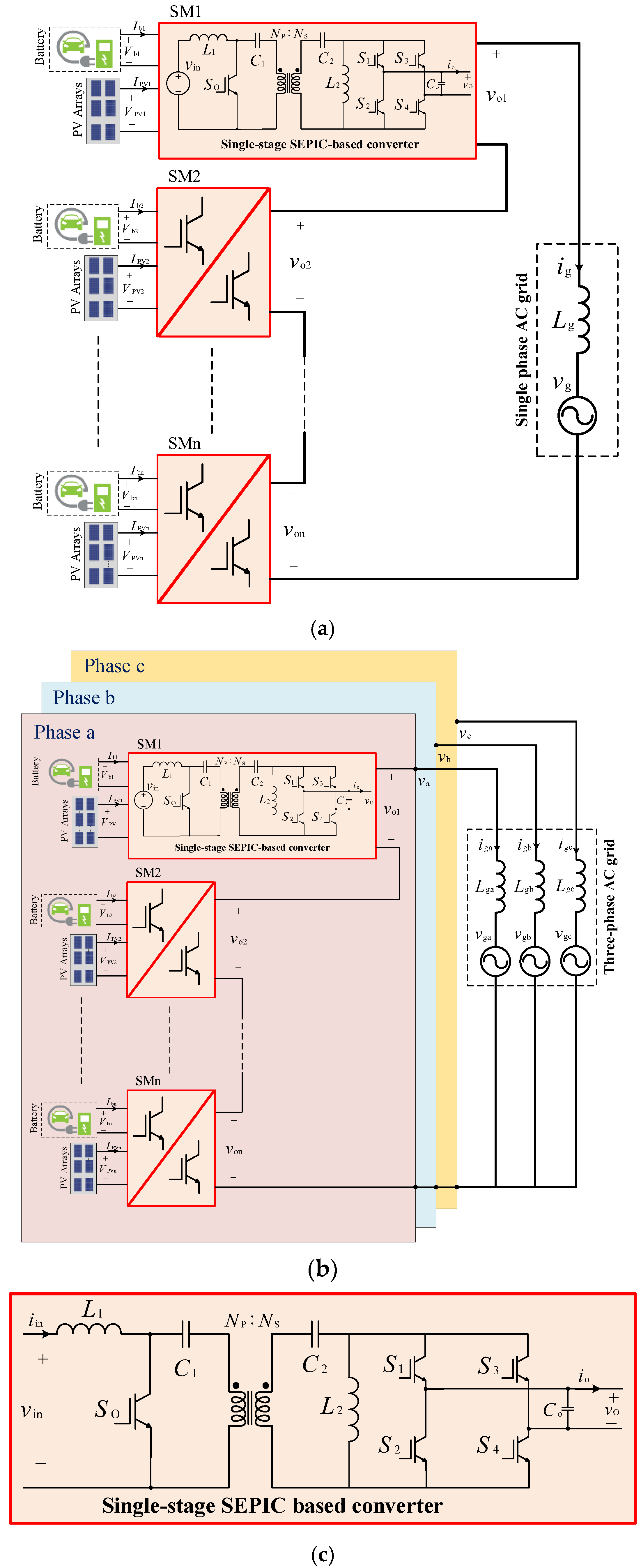
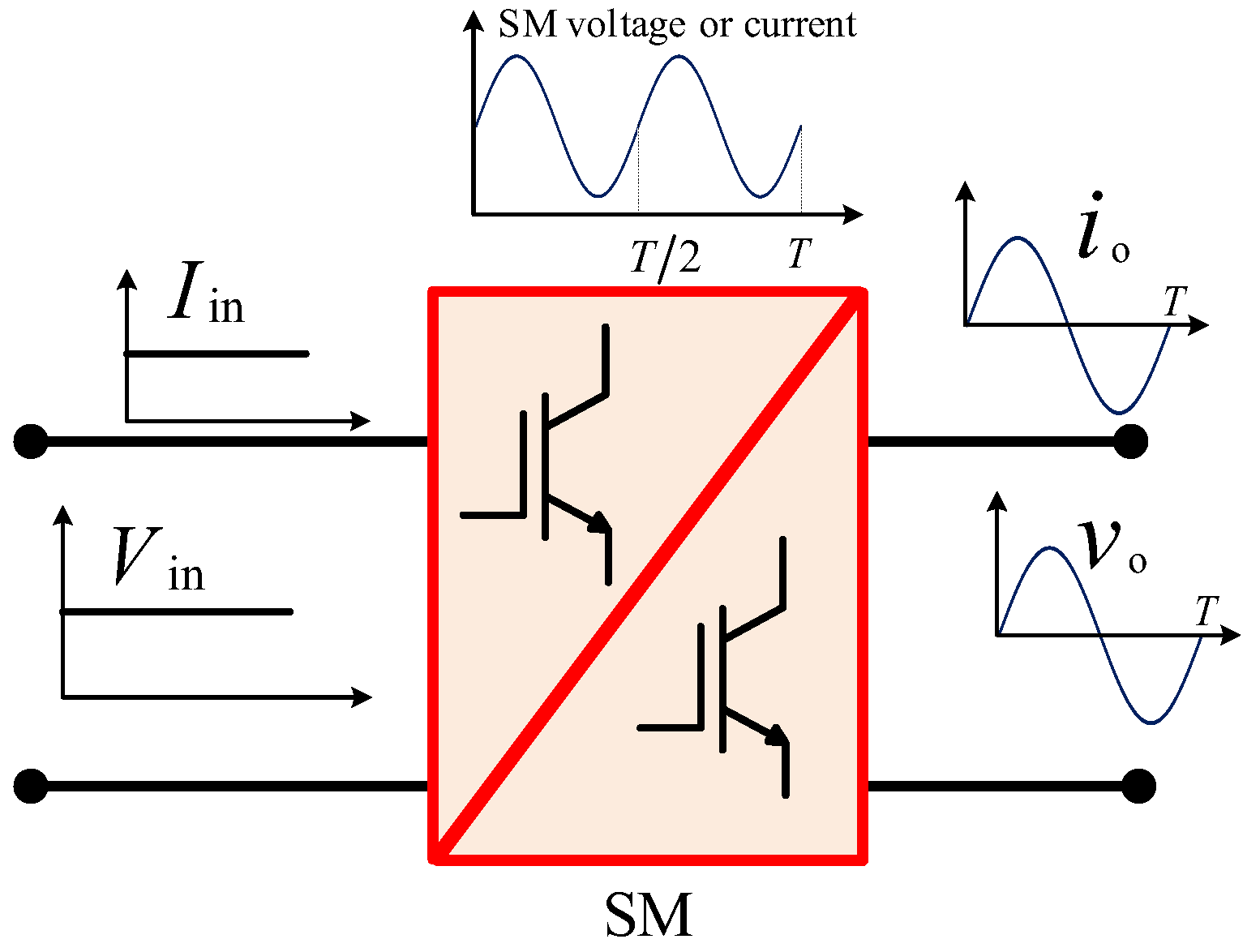
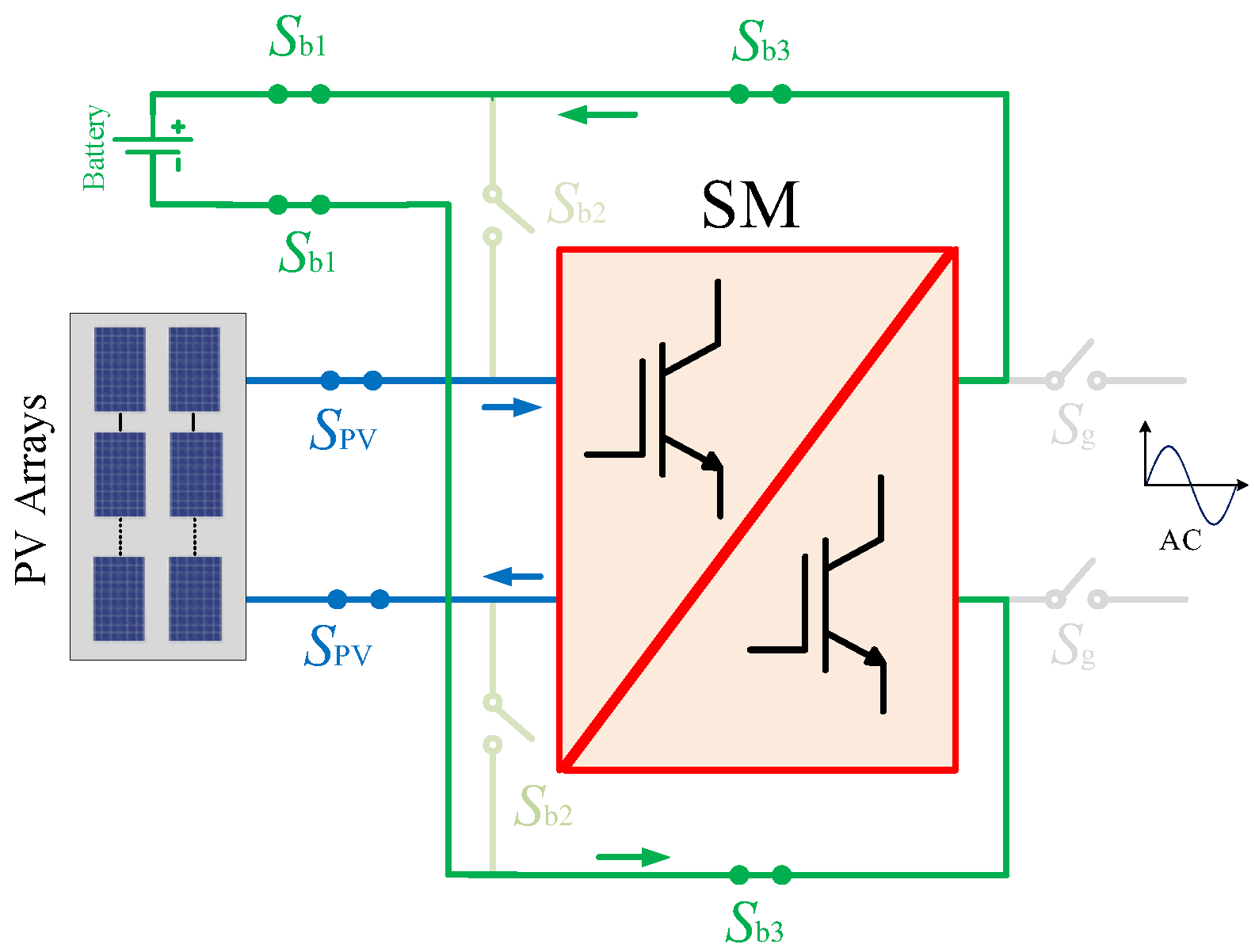
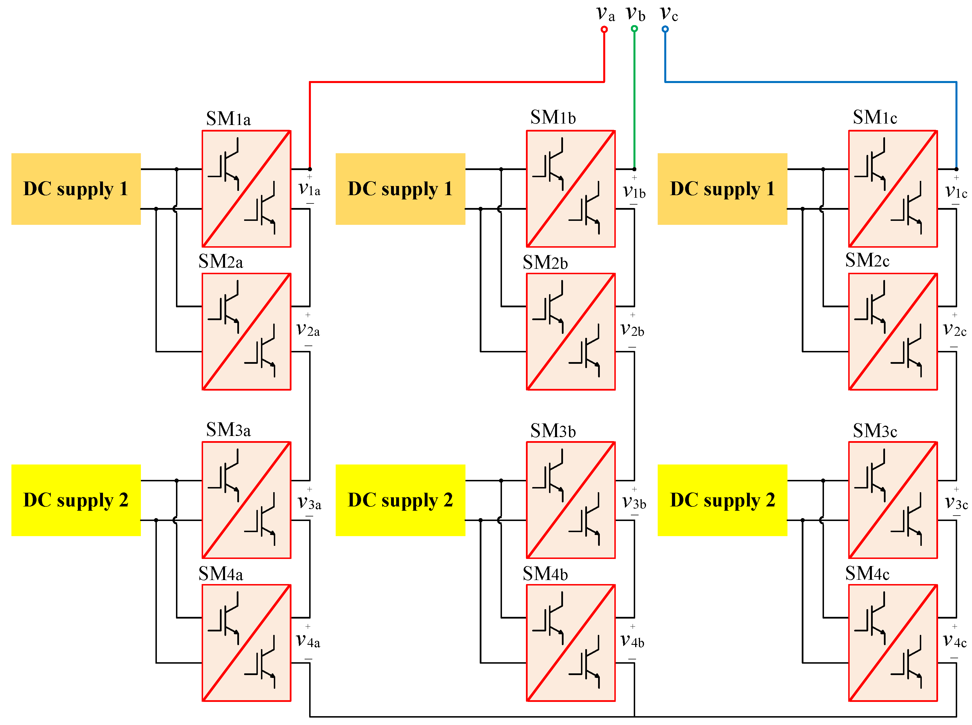
2. The Proposed MMC Topology

Figure 1 shows single- and three-phase layouts of the proposed MMC topology for large-scale photovoltaic plants (LSPVs) based on the isolated single-stage SEPIC converter together with battery electric vehicle (BEV) as the energy storage system (EES).
To support DC/DC (PV modules to EES) and DC/AC (PV or EES to the AC grid) operation modes, the selected SM must be able to provide (i) flexible voltage higher or lower than the input voltages from the PV modules or battery (ii) galvanic isolation between the input and output sides to meet the safety standards of the grid. The SEPIC-based converter is adopted in this work as the SM has outstanding features, including low input ripple current, high efficiency, high power factor (PF), and flexible output voltage higher or lower than the input voltage. As seen in Figure 1c, the SEPIC SM consists of five semiconductor switches (So, S1S4), two inductors, L1 and L2, and three capacitors, C1, C2, and Co. Moreover, a high-frequency transformer (HFT) with turns’ ratio Ns:NP can be employed, so the input and output sides are galvanically isolated to comply with the grid’s codes. In addition, the HFT can provide additional voltage boosting if required. The SM’s operation modes and steady state-space representation will be presented in the following subsections.

3. System-Level Operation

Assuming that the three-phase layout of the proposed MMC topology is connected to the three-phase MV grid through the grid inductors (Lga, Lgb, and Lgc) with internal resistances (rga, rgb, and rgc), the total voltage delivered per phase at the grid side equals the summation of the individual voltages of the series-connected SMs and can be expressed as
i = 1 n v oi = V o sin ( ω t + θ )
with Vo and θ being the magnitude of the output voltage of the SMs and the phase-shift with respect to the grid voltage, respectively.
If the three-phase MMC delivers the active power P to the AC grid at a power factor cosφ, then the magnitude of the output voltage Vo, the phase-shift θ, and the per-phase magnitude of the output current Ig for the grid voltage vg(t) = Vg sin(ɷt) can be written as
I g = 2 P 3 V g cos ( φ )
θ = tan 1 [ r g I g sin ( φ ) + ω L g I g cos ( φ ) V g + r g I g cos ( φ ) ω L g I g sin ( φ ) ]
V o = [ V g + r g I g cos ( φ ) ω L g I g sin ( φ ) cos ( θ ) ]

4. Modes of Operation

For each SM, single-pole-double-through (SPDT) relays SPV and Sbj (j = 1, 2, 3) can be used, as shown in Figure 2, to connect the SM to the PV array the battery pack, or the AC grid. Thus, the proposed MMC can operate in two different modes (DC/DC and DC/AC), depending on the connection of the relays. In addition, a pair of SPDT relays, Sg, is used to connect the AC grid to the output terminals of the SM. The resulting modes of operations will be discussed in more detail in the following section.

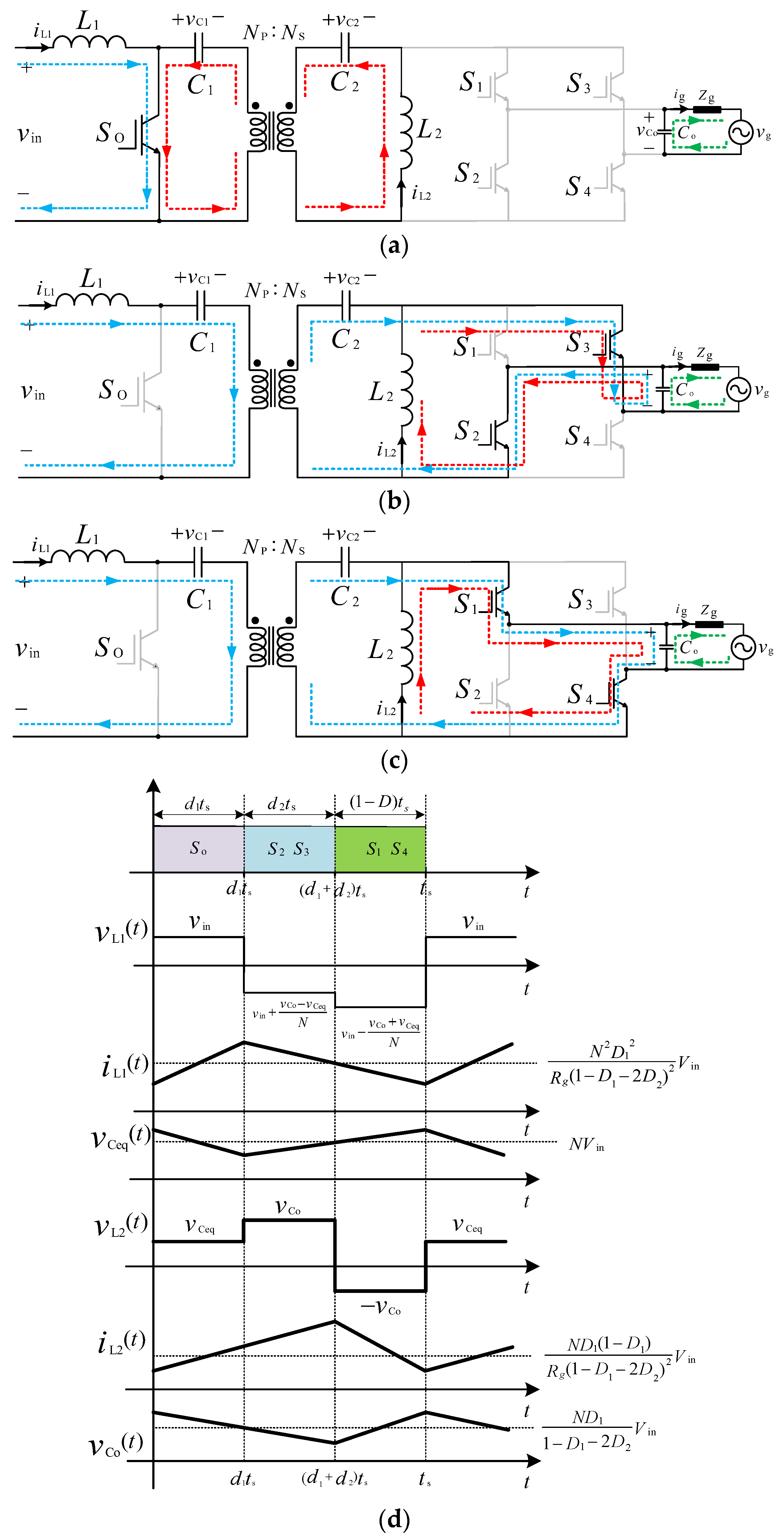
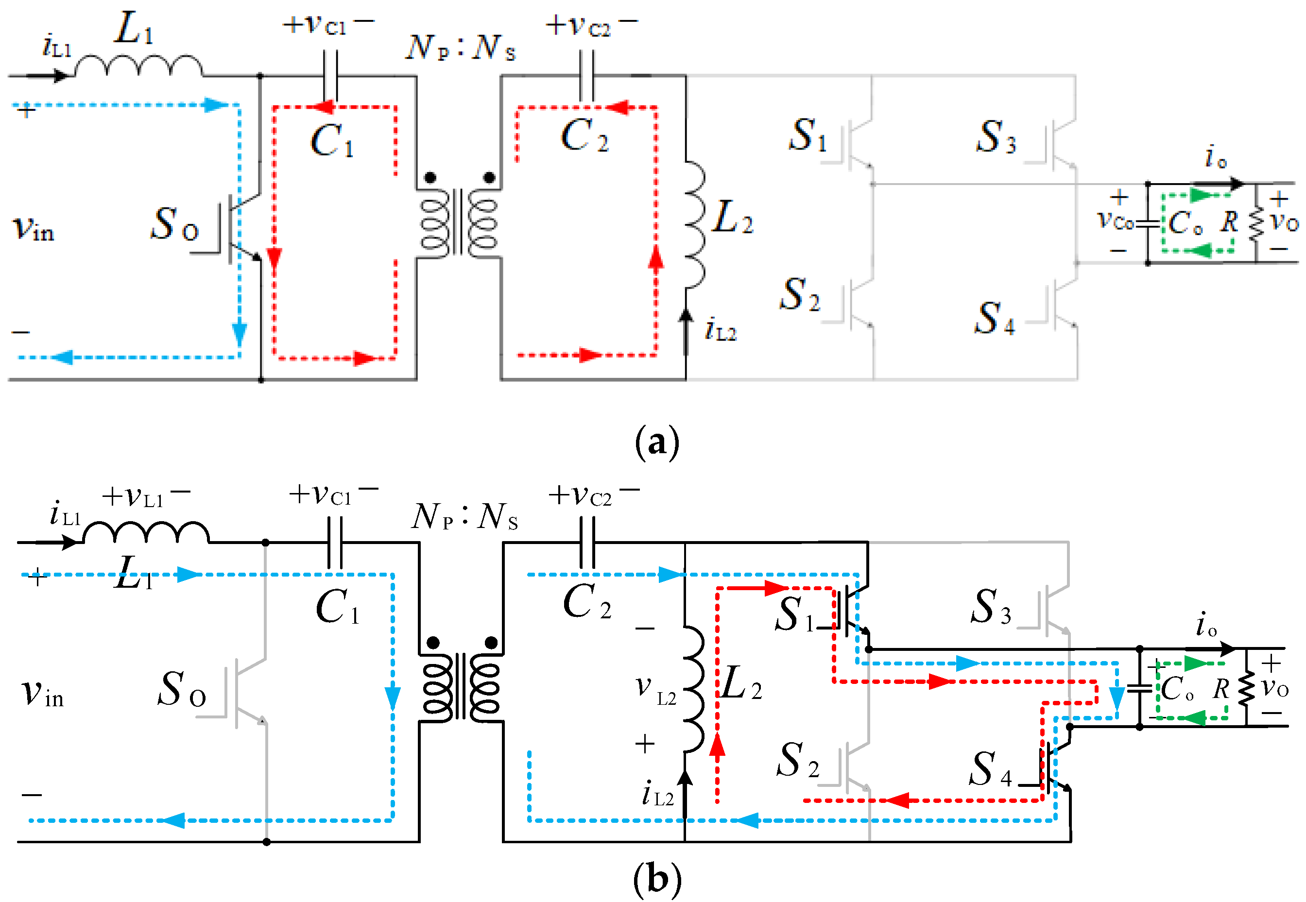
4.1. DC/AC Operation (from PV Modules/Batteries to the AC Grid)

The SPDT relays connections when the real power is delivered from the PV modules, and the battery packs to the AC grid are shown in Figure 3a,b, respectively. To deliver power from the PV modules to the AC grid (Figure 3a), all the SPDT relays are opened except Spv and Sg. Thus, the PV modules will be able to support the AC grid, especially during daylight when the PV arrays are generating their highest attainable power. If the power provided by the PV modules is not sufficient to support the AC grid, the SPDT relays Sbj (j = 1, 2) can be switched on instead of the relays Spv (Figure 3b). In both cases, the SEPIC-based SM operates as a DC/AC converter.
It should be mentioned that in the DC/AC mode, the PV modules/the battery packs are required to operate at constant voltages and currents, and therefore the input current to the SM should be constant and continuous. However, as the single-phase SEPIC SMs are connected to the single-phase AC grid, the output current and voltage are sinusoidal at the grid frequency (50/60 Hz). Consequently, the second-order harmonic will be re-elected to the input side, causing the input current to have an undesired second-order harmonic which will interrupt the maximum power point tracker (MPPT). Therefore, as shown in Figure 4, the SEPIC-based SM converter should be able to store the second-order voltage or current harmonics in a storage element. To do so, the SM is designed and controlled to operate in three subintervals. In other words, an extra subinterval is considered to store the second-order component in the inductor L2.
The DC/AC mode includes three subintervals whose equivalent circuits for the positive half-cycle (when vg > 0) are illustrated in Figure 5a–c:
Subinterval 1(0 ≤ t < ton1): During the first subinterval (see Figure 5a), the switch So is turned ON, so the inductor L1 is being charged by the input DC voltage (from either PV modules or the battery packs), and its current iL1 is linearly increasing. The capacitors C1 and C2 discharge into the inductor L2, increasing its current iL2 in a straight line. The output capacitor Co, on the other hand, discharges into the AC grid. This mode will last for ton1 = d1.ts, with d1 and ts being the duty-cycle ratio and the switching time of the SM.
Subinterval 2(ton1t < ton1+ ton2): During this subinterval (ton2 = d2·ts), the switch SO is turned OFF. As a result, the inductor L1 discharge into the capacitors C1 and C2, while the inductor L2 is still being charged by turning S2 and S3 ON from the output capacitor Co. Therefore, this subinterval provides the required decoupling between the input and output sides, as shown in Figure 5b.
Subinterval 3(ton1+ ton2t < ts): During this subinterval ((1 − d1d2)ts), the switch SO is kept in the OFF state, so the inductor L1 is still discharging into the capacitors C1, C2, and Co, increasing their voltages. For the positive half-cycle (vg > 0), the switches S1 and S4 are turned ON. Therefore, the inductor L2 discharges into the output capacitor Co (see Figure 5c).
The key output waveforms for the positive half-cycle (vg > 0) are presented in Figure 5d, in which for N = NS/NP, the voltage vCeq(t) and the equivalent capacitor Ceq are as below:
{ v C e q ( t ) = N v C 1 ( t ) + v C 2 ( t ) C e q = C 1 C 2 C 1 + N 2 C 2
In addition, D represents the duty-cycle ratio corresponding to the main switch So, which in this mode is equal to
D ( t ) = d 1 ( t ) + d 2 ( t ) = V O V O + N V in

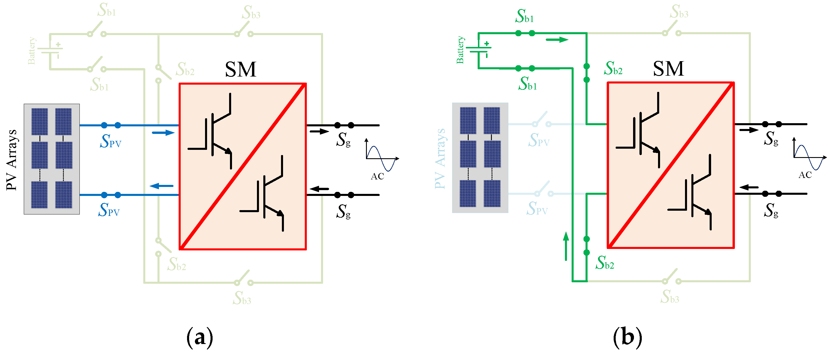
4.2. DC/DC Operation (Batteries Being Charged by the PV Modules)

The active power can be transferred from the PV modules to the battery packs as long as the AC grid does not demand active power support from the PV modules during the daytime. Accordingly, the SPDT relays Sbj (j = 1, 3) and SPV are connected while disconnecting relays Sg, as shown in Figure 6.
This mode includes two subintervals whose equivalent circuits are demonstrated in Figure 7a,b:
Subinterval1 (0 ≤ t < ton): During the first subinterval (see Figure 7a), the switch So is turned ON, resulting in the inductor L1 being charged by the input DC voltage (from the PV module). Concurrently, the capacitors C1 and C2 are discharging into the inductor L2. Therefore, iL1 and iL2 are linearly increasing. The output capacitor Co, on the other hand, discharges into the battery pack. The duration of this period is ton = d·ts, with and ts being the duty-cycle ratio and the switching time of the SM.
Subinterval2 (tont < ts): During this subinterval ((1 − d)ts), switch So is turned OFF. Therefore, the inductor L1 discharge into the capacitors C1 and C2, leading them to be charged. Switches S1 and S4 are turned ON to mimic the operation of the typical SEPIC converter and provide a path for the current passing the inductor L2 to flow through the output capacitor Co, increasing its voltage (see Figure 7b).
The key output waveforms are presented in Figure 7c, where for N = NS/NP, the voltage vceq(t) and the equivalent capacitor Ceq are in (5).

5. State-Space Modelling of the Proposed SEPIC-Based SM

As described in the previous section, the proposed SEPIC-based SM operates in two and three states for DC/DC and DC/AC modes, respectively. The states can be averaged over a switching period to extract the state-space model [28,29].

5.1. DC/AC Operation (from PV Modules/Batteries to the AC Grid)

The state-space model of the proposed SEPIC-based SM can be developed over the switching period ts by writing a set of first-order differential equations governing the circuit:
{ x ˙ ( t ) = A i x ( t ) + B i u ( t ) y ( t ) = C i x ( t )
where the matrices Ai, Bi, and Ci (where i = 1, 2, 3) represent the system, the input, and the output matrices of the three subintervals in Figure 5, respectively. The state vector x(t) can be expressed as x(t) = [iL1(t) vCeq(t) iL2 (t) vCo(t)]T. The input signal u(t) = vin(t) is the output voltage of PV modules or battery packs, and the output y(t) = vCo(t) is the output capacitor voltage.
The three subintervals of the DC/AC operation mode are time-weighted and averaged to extract the nonlinear averaged state-space model as
{ x ¯ ˙ ( t ) = A x ¯ ( t ) + B u ¯ ( t ) y ¯ ( t ) = C x ¯ ( t )
where the matrices A, B, and C are as follows [28]:
{ A = A 1 d 1 + A 2 d 2 + A 3 ( 1 d 1 d 2 ) B = B 1 d 1 + B 2 d 2 + B 3 ( 1 d 1 d 2 ) C = C 1 d 1 + C 2 d 2 + C 3 ( 1 d 1 d 2 )
The nonlinear averaged model in (8) can be linearized under the small-signal assumption by finding deviations around steady-state operating points (the roots of x ¯ ˙ ( t ) = A x ¯ ( t ) + B u ¯ ( t ) = 0 ) to derive required transfer functions. After applying Laplace, the small-signal model can be represented as:
[ i ˜ ˙ L 1 ( s ) v ˜ ˙ Ceq ( s ) i ˜ ˙ L 2 ( s ) v ˜ ˙ C o ( s ) ] = A inv [ i ˜ L 1 ( s ) v ˜ Ceq ( s ) i ˜ L 2 ( s ) v ˜ C o ( s ) ] + B inv [ v ˜ in ( s ) d ˜ 1 ( s ) d ˜ 2 ( s ) ]
v ˜ o ( s ) = C inv [ i ˜ L 1 ( s ) v ˜ Ceq ( s ) i ˜ L 2 ( s ) v ˜ C o ( s ) ]
where the matrices Ainv, Binv, and Cinv at steady-state operating points are as follows:
A inv = [ i ¯ ˙ L 1 ( t ) i L 1 ( t ) i ¯ ˙ L 1 ( t ) v Ceq ( t ) i ¯ ˙ L 1 ( t ) i L 2 ( t ) i ¯ ˙ L 1 ( t ) v C o ( t ) v ¯ ˙ C e q ( t ) i L 1 ( t ) v ¯ ˙ C e q ( t ) v Ceq ( t ) v ¯ ˙ C e q ( t ) i L 2 ( t ) v ¯ ˙ C e q ( t ) v C o ( t ) i ¯ ˙ L 2 ( t ) i L 1 ( t ) i ¯ ˙ L 2 ( t ) v Ceq ( t ) i ¯ ˙ L 2 ( t ) i L 2 ( t ) i ¯ ˙ L 2 ( t ) v C o ( t ) v ¯ ˙ C o ( t ) i L 1 ( t ) v ¯ ˙ C o ( t ) v Ceq ( t ) v ¯ ˙ C o ( t ) i L 2 ( t ) v ¯ ˙ C o ( t ) v C o ( t ) ] = [ 0 ( 1 D 1 ) N L 1 0 ( 1 D 1 2 D 2 ) N L 1 ( 1 D 1 ) N C eq 0 D 1 C eq 0 0 D 1 L 2 0 ( 1 D 1 2 D 2 ) L 2 ( 1 D 1 2 D 2 ) N C o 0 ( 1 D 1 2 D 2 ) C o 1 R g C o ]
B inv = [ i ¯ ˙ L 1 ( t ) v in ( t ) v ¯ ˙ C e q ( t ) v in ( t ) i ¯ ˙ L 2 ( t ) v in ( t ) v ¯ ˙ C o ( t ) v in ( t ) i ¯ ˙ L 1 ( t ) d 1 ( t ) v ¯ ˙ C e q ( t ) d 1 ( t ) i ¯ ˙ L 2 ( t ) d 1 ( t ) v ¯ ˙ C o ( t ) d 1 ( t ) i ¯ ˙ L 1 ( t ) d 2 ( t ) v ¯ ˙ C e q ( t ) d 2 ( t ) i ¯ ˙ L 2 ( t ) d 2 ( t ) v ¯ ˙ C o ( t ) d 2 ( t ) ] = [ 1 L 1 ( V Ceq + V Co ) N L 1 2 V Co N L 1 0 ( I L 1 + N I L 2 ) N C eq 0 0 0 ( V Ceq + V Co ) L 2 ( I L 1 + N I L 2 ) N C o 2 V Co L 2 2 N C o ( I L 1 + N I L 2 ) ]
C inv = [ v ¯ C o ( t ) i L 1 ( t ) v ¯ C o ( t ) v C e q ( t ) v ¯ C o ( t ) i L 2 ( t ) v ¯ C o ( t ) v C o ( t ) ] = [ 0 0 0 1 ]
Finally, the line-to-output (known as the perturbation transfer function) and line-to-control transfer functions are derived:
G v in ( s ) = v ˜ o ( s ) v ˜ in ( s ) | d ˜ 1 ( s ) = d ˜ 2 ( s ) = 0 = C inv ( s I A inv ) 1 B inv
G d 1 ( s ) = v ˜ in ( s ) d ˜ 1 ( s ) | d ˜ 2 ( s ) = 0 = C inv ( s I A inv ) 1 B inv
G d 2 ( s ) = v ˜ o ( s ) d ˜ 2 ( s ) | v ˜ in ( s ) = d ˜ 1 ( s ) = 0 = C inv ( s I A inv ) 1 B inv
where I is the unity matrix. The control transfer functions Gd1 and Gd2 (derived by neglecting input voltage disturbance) will later be used in the control loops of the input voltage vin (PV or battery voltage) and output voltage vo (grid voltage), respectively.

5.2. The Calculated Duty-Cycle Ratios for Second-Order Harmonic Elimination

The duty-cycle ratios d1 and d2 can be calculated to eliminate the second-order harmonic component. The instantaneous power equation of the converter can be obtained from
V in I in = L 2 d i L 2 d t . i L 2 + v o ( t ) i o ( t )
Assuming that the current through L2 has a DC component plus an AC component of 2ω as
i L 2 = I L 2 + I 2 n d sin ( 2 ω t + φ )
with I2nd being the amplitude of the second-order component. Assuming a resistive output load, the desired output voltage and current can be expressed as
{ i o ( t ) = I o sin ( 2 ω t ) v o ( t ) = V o sin ( 2 ω t )
After substituting (19) and (20), Equation (18) can be rewritten as
V in I in = 2 ω I L 2 I 2 n d L 2 cos ( 2 ω t + φ ) + ω L 2 I 2 n d 2 sin ( 4 ω t + φ ) 0 + V o I o 2 V o I o 2 cos ( 2 ω t )
Assuming that ηSM = 100% (i.e., P in = V in I in = P o = V o I o / 2 ), Equation (21) can be rewritten as
2 ω I L 2 I 2 n d L 2 cos ( 2 ω t + φ ) = V o I o 2 cos ( 2 ω t )
Therefore, the amplitude and phase of the second-order component can be extracted as
{ φ = π 2 I L 2 = I 2 nd = V o I o 4 ω L 2
As the input DC current (battery/PV current) needs to be kept constant, the first row of the average model equations in (8) must be zero:
x ¯ ˙ 1 ( t ) = i ¯ ˙ L 1 ( t ) = ( 1 d 1 f f ( t ) ) N L 1 v ¯ C e q ( t ) + ( 1 d 1 f f ( t ) 2 d 2 f f ( t ) ) N L 1 v ¯ o ( t ) + 1 L 1 v ¯ in ( t ) = 0
with d1ff and d2ff being feed-forward duty-cycle ratios. Finally, Equations (24) and (6) can be solved simultaneously to extract d1ff and d2ff as follows:
{ d 1 f f ( t ) = v ¯ o ( t ) ( v ¯ C e q ( t ) v ¯ o ( t ) ) + N v ¯ in ( t ) ( v ¯ C e q ( t ) N v ¯ in ( t ) ) ( v ¯ C e q ( t ) v ¯ o ( t ) ) ( N v ¯ in ( t ) + v ¯ o ( t ) ) d 2 f f ( t ) = D ( t ) d 1 f f ( t )

5.3. DC/DC Operation (PV Modules to Batteries)

Using the same procedure as DC/AC operation mode, the two subintervals of the DC/DC operation mode are time-weighted and averaged to extract the nonlinear averaged state-space model as follows [28,29]:
{ x ¯ ˙ ( t ) = A x ¯ ( t ) + B u ¯ ( t ) y ¯ ( t ) = C x ¯ ( t )
where the matrices A, B, and C are as follows:
{ A = A 1 d + A 2 ( 1 d ) B = B 1 d + B 2 ( 1 d ) C = C 1 d + C 2 ( 1 d )
The nonlinear averaged model in (26) can be linearized under the small-signal assumption by finding deviations around steady-state operating points (the roots of x ¯ ˙ ( t ) = A x ¯ ( t ) + B u ¯ ( t ) = 0 ) to derive required transfer functions. After applying Laplace, the small-signal model can be represented as
[ i ˜ ˙ L 1 ( s ) v ˜ ˙ Ceq ( s ) i ˜ ˙ L 2 ( s ) v ˜ ˙ C o ( s ) ] = A dc [ i ˜ L 1 ( s ) v ˜ Ceq ( s ) i ˜ L 2 ( s ) v ˜ C o ( s ) ] + B dc [ v ˜ in ( s ) d ˜ ( s ) ]
v ˜ o ( s ) = C dc [ i ˜ L 1 ( s ) v ˜ Ceq ( s ) i ˜ L 2 ( s ) v ˜ C o ( s ) ]
where the matrices Adc, Bdc, and Cdc at steady-state operating points are as follows:
A dc = [ 0 ( 1 D ) N L 1 0 ( 1 D ) N L 1 ( 1 D ) N C eq 0 D C eq 0 0 D L 2 0 ( 1 D ) L 2 ( 1 D ) N C o 0 ( 1 D ) C o 1 R C o ]
B dc = [ 1 L 1 ( V Ceq + V Co ) N L 1 0 0 0 ( I L 1 + N I L 2 ) N C eq ( V Ceq + V Co ) L 2 ( I L 1 + N I L 2 ) N C o ]
C dc = [ 0 0 0 1 ]
Finally, the line-to-output and line-to-control transfer functions are derived:
G v in ( s ) = v ˜ o ( s ) v ˜ in ( s ) | d ˜ ( s ) = 0 = C dc ( s I A dc ) 1 B dc
G d ( s ) = v ˜ in ( s ) d ˜ ( s ) = C dc ( s I A dc ) 1 B dc
The transfer function Gd is derived by neglecting input voltage disturbance and will later be used in the control loop of the input voltage vin (the battery voltage).

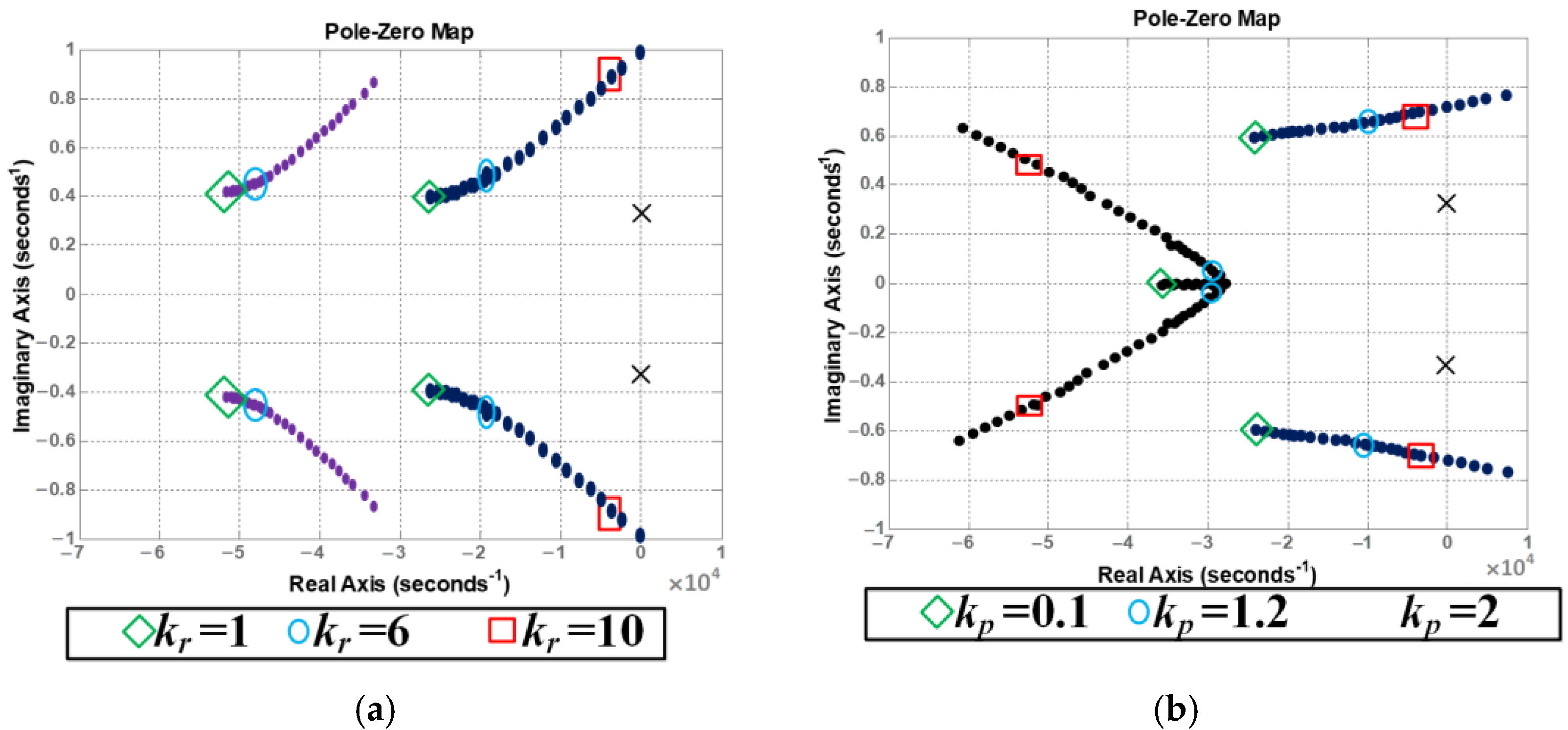
6. Controller Design

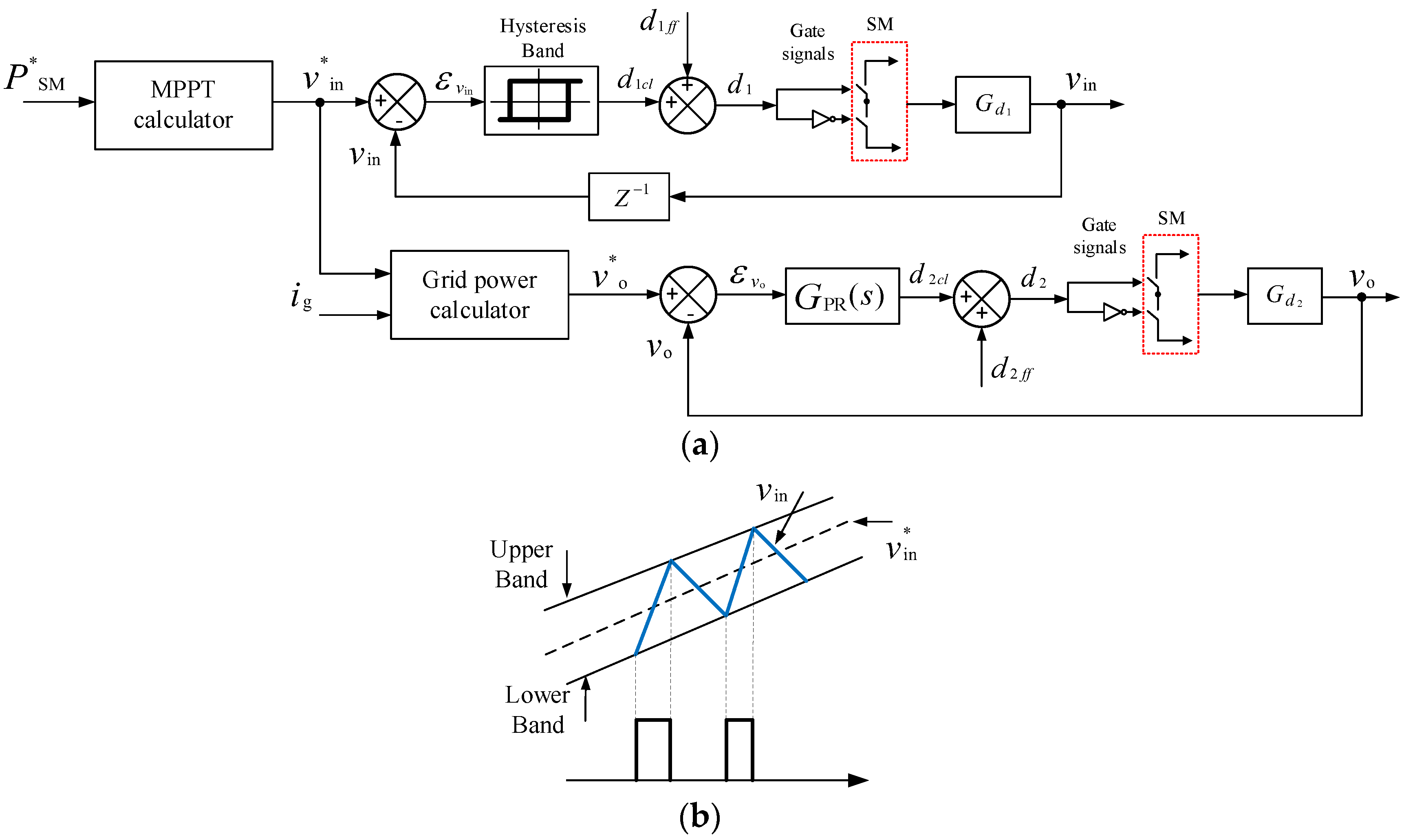
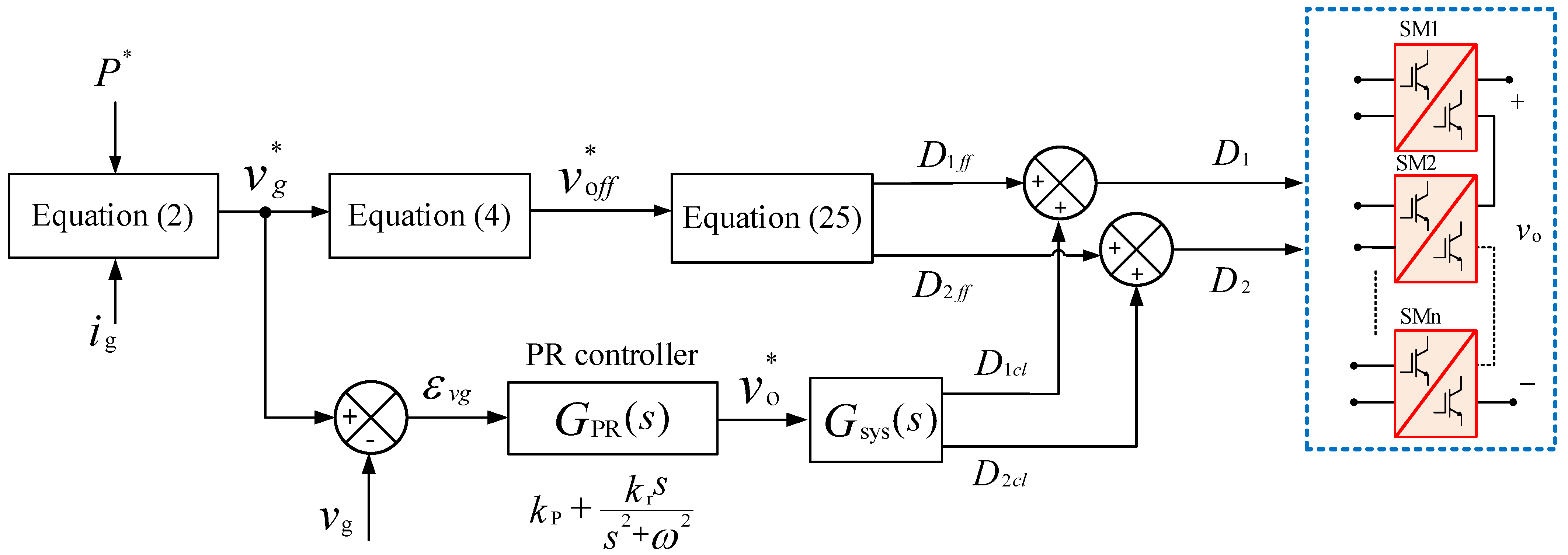
6.1. DC/AC Operation (from PV Modules/Batteries to the AC Grid)

Figure 8 demonstrates the SM control design when the proposed MMC topology operates as a DC/AC converter, and the power flows from the PV modules to the AC grid. The active power P, in this case, is determined by the maximum available power from the PV modules. For simplicity, it is assumed that all the PV modules operate under the same weather conditions (irradiance, temperature, partial shading, etc.). The reference input (PV) voltage vin* is computed from the MPPT controller. Then, a simple hysteresis-based sliding mode controller controls the actual input voltage vin [30]. A proportional-resonant (PR) controller tuned at the grid frequency ωo = 2πf is utilized to control the output voltage vo.
Figure 9 depicts the SM control design when the proposed MMC topology operates as an inverter, and the power flows from the battery packs to the AC grid. Again, hysteresis and PR controllers control the input and output voltages, respectively. Compared to the previous case with PV modules as the input power supply, the active power is determined by the optimal discharge current from the batteries to maximize their effective lifetime and capacity. In addition, the batteries’ discharging currents are flexible as there is no maximum power point to operate at. Instead, the reference current is chosen based upon the nominal values recommended by the manufacturer to maximize their lifetime. However, the control scheme after the MPPT or the battery voltage calculator will remain unchanged.
As discussed in Section 4.1, the additional subinterval in DC/AC operation modes (from PV modules/batteries to the AC grid) provides an extra degree of freedom to control input and output sides together. In other words, the second-order harmonic component is trapped; hence, the input current will be kept constant while generating sinusoidal output voltages and currents.
For the output side control, the feed-forward duty-cycle ratio d2ff will generate the output voltage vo depending on the measured grid voltage and the required output power. The closed-loop PR controller will fix the error in calculation due to the parasitic resistances of the passive elements, semiconductor switches, or any other mismatches by adding the closed-loop duty-cycle ratio d2. The PR controller is tuned at the grid frequency ωo = 2πfo as:
G P R ( s ) = k p + k r s s 2 + ω o 2
To ease the selection of the proportional gain kp and the resonant gain kr, an average value of d2 is selected at ½ in Gd2 with the transfer function values listed in Table 1. The SISOTOOL interactive toolbox in MATLAB/SIMULINK® is used to select reasonable values for the controller gains by plotting the root loci of the closed-loop system in two different ways. Firstly, the proportional gain kp is kept constant at 1, and the resonant gain kr is increased in the range of [1:10]. Secondly, kr is kept constant at 1 while kp is changed from [0.1:2]. The resultant root loci are shown in Figure 10. The values of the gains are selected in these ranges to keep the system stable, increase the controller’s bandwidth, and reduce the overshoot. Reasonable system performance in terms of compromising bandwidth and stability is chosen when kp = 1.2 and kr = 6.

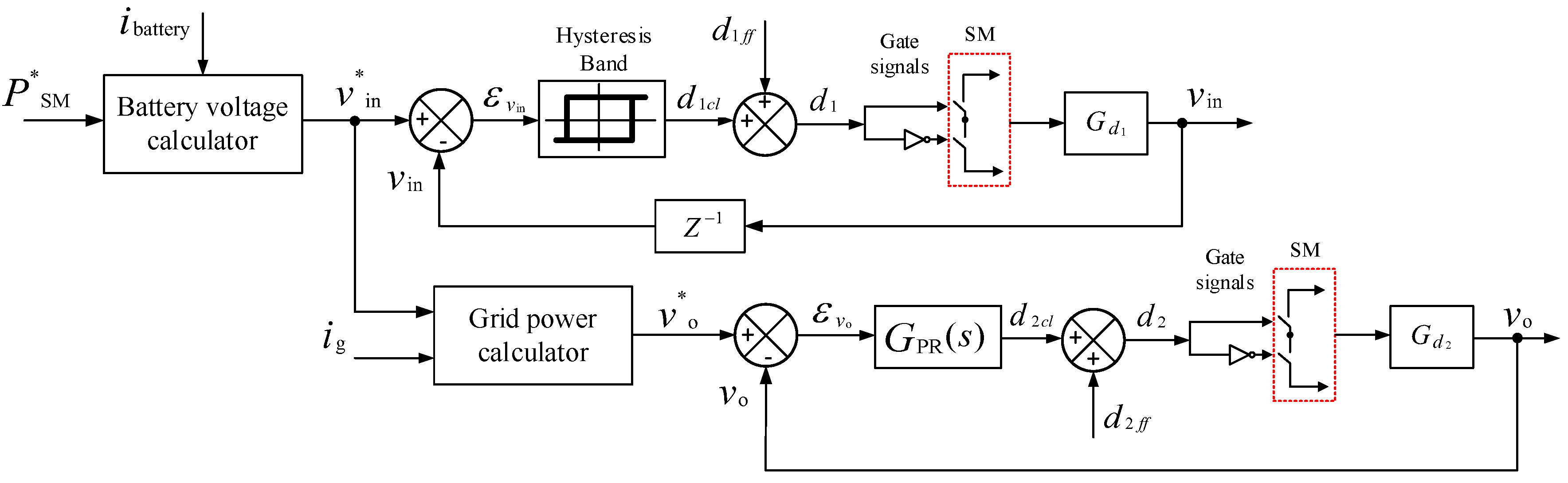
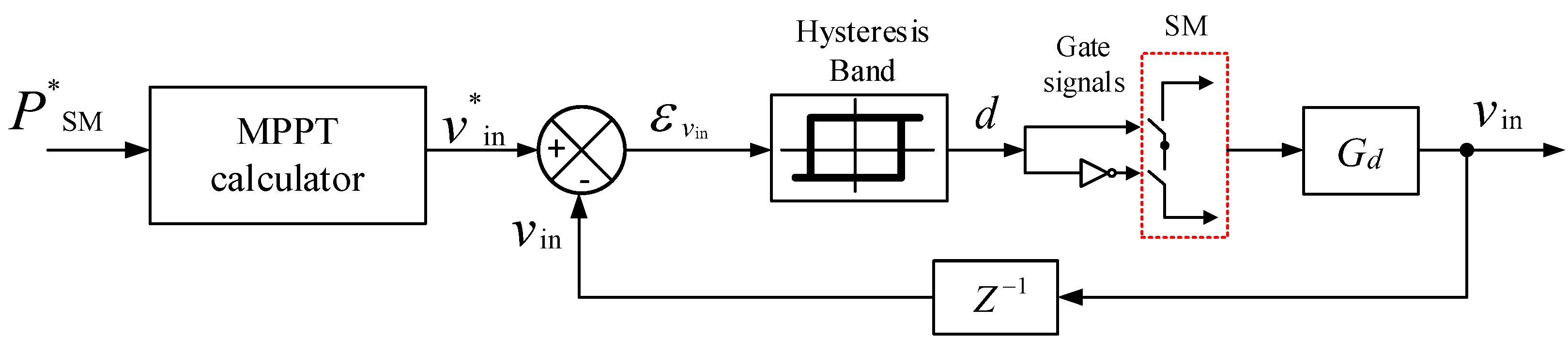
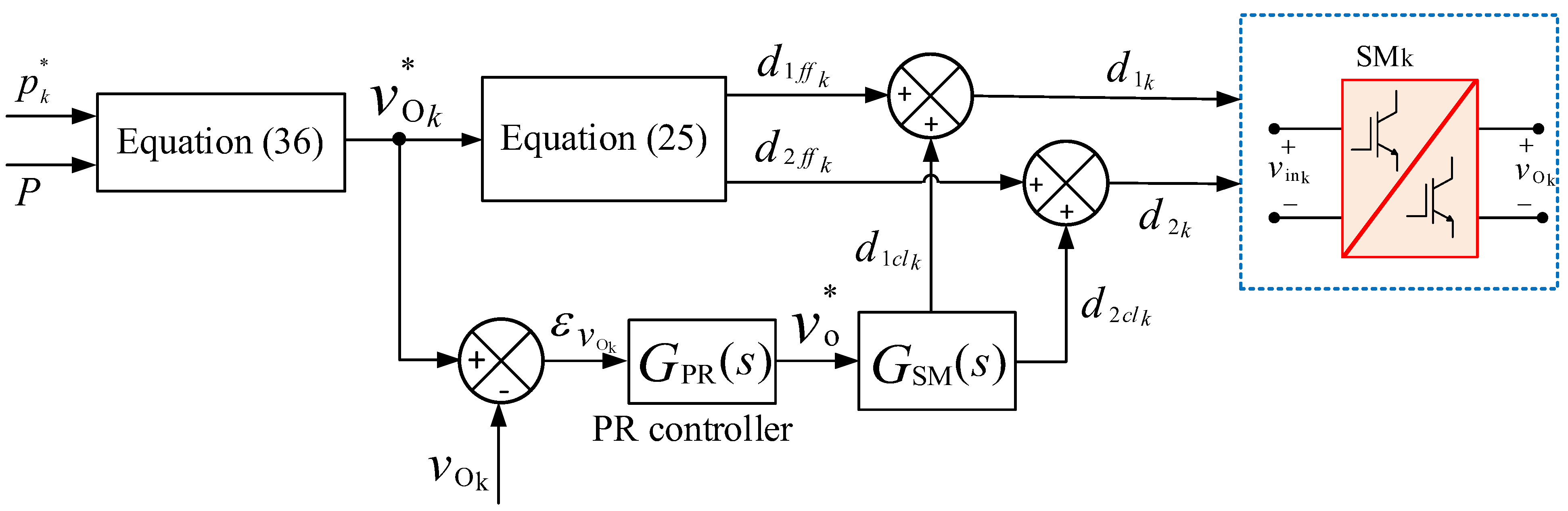
6.2. DC/DC Operation (from PV Modules to Battery Packs)

Figure 11 shows the SM-level control design when the proposed MMC topology is used to charge the PV batteries. The active power P is determined by the maximum available power from the PV modules, and the reference input voltage vin* is calculated from the MPPT controller. Then, the actual input voltage vin is controlled by a simple hysteresis controller. For simplicity, it is assumed that the PV power will not exceed the rated power of the SMs and the batteries, so the output voltage (battery’s voltage) can be left uncontrolled.

7. Verification

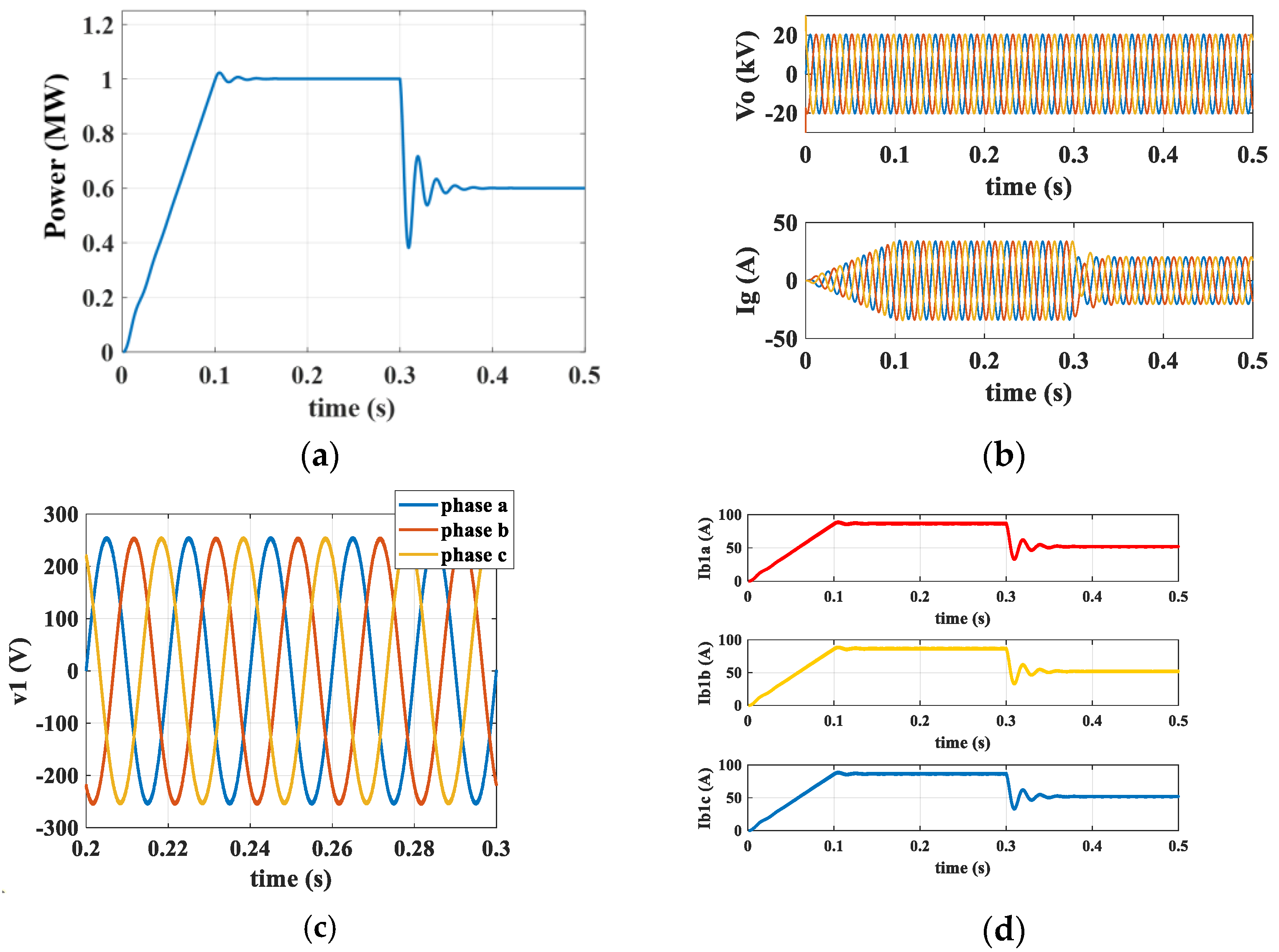
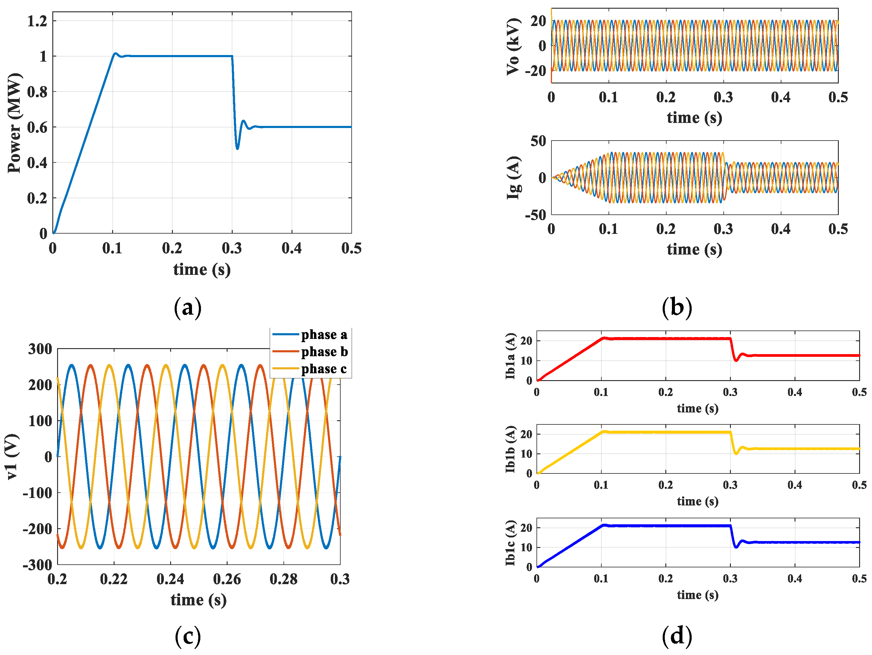
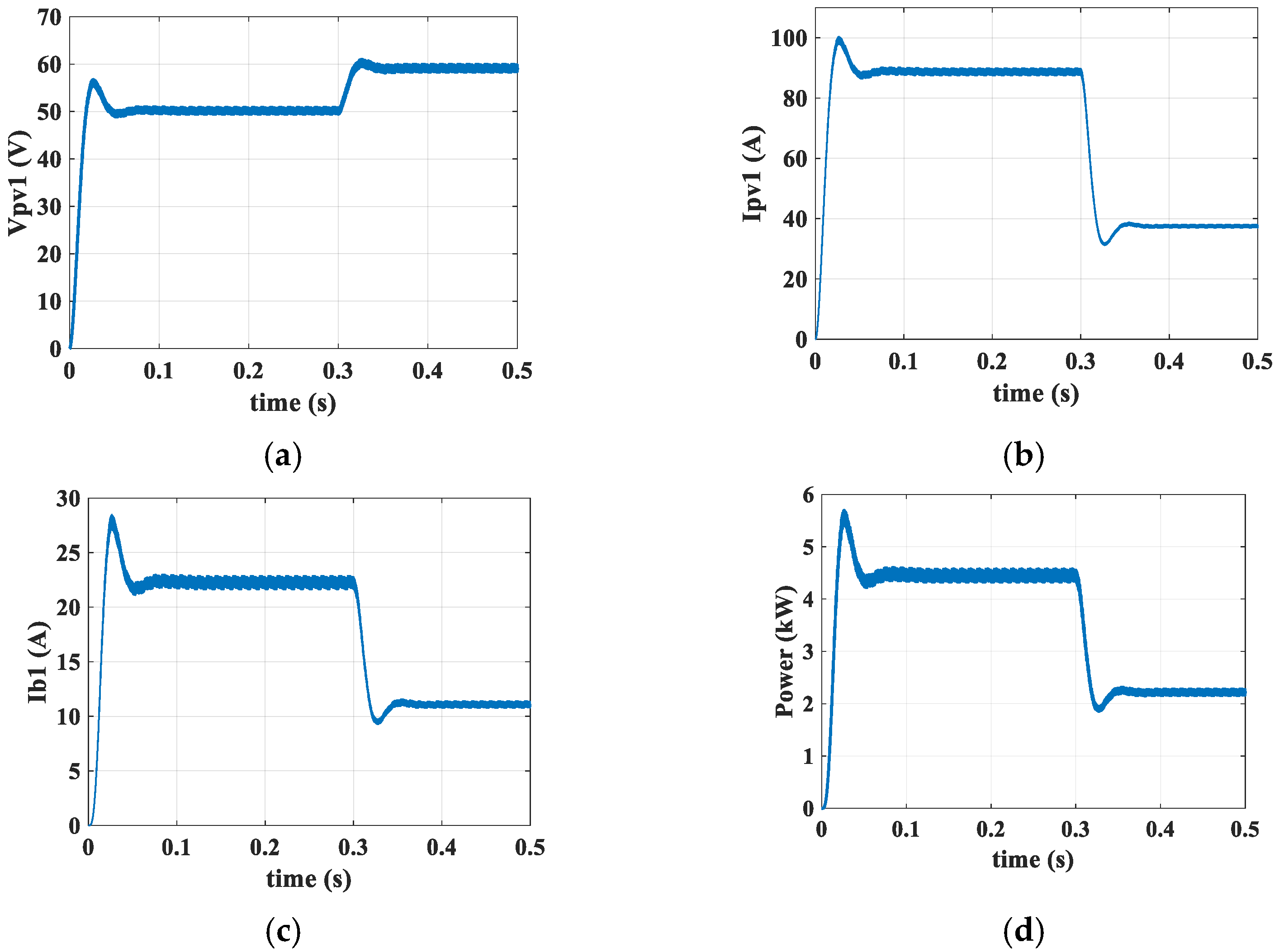
7.1. Simulation Study

The parameters listed in Table 1 are used in MATLAB/Simulink to verify the operation modes of the proposed MMC topology (i.e., DC/AC (from PV modules/batteries to AC grid) and DC/DC (from PV modules to batteries)) in two case studies.
Figure 12 shows the simulation results for the DC/AC operation mode and when the power is transferred from the PV modules to the AC grid. The total output power in Figure 12a increases from zero to the maximum of around 1 MW in 100 ms and then decreases to around 0.6 MW at t = 300 ms because the irradiance dropped to 60% for all PV modules simultaneously at t = 300 ms to simulate the dynamic response. The grid voltage and current are shown in Figure 12b. The output voltage and the input (PV array’s) current of the first SMs in the three phases are also plotted together in Figure 12c. Figure 12d shows the input PV current of the first SMs in the three phases where the controller has successfully removed the second-order harmonic components from each PV module.
Figure 13 shows the simulation results to test the operation when the batteries are used to support the grid. As shown in Figure 13a, the power transferred to the grid increases from zero to the maximum of 1 MW in 100 ms. The grid voltage and current are shown in Figure 13b. The output voltage and input (battery’s) current of the first SMs in the three phases are plotted in Figure 13c,d, respectively.
Figure 14 shows the simulation results when the SM is controlled to supply the batteries at 200 V by the PV modules at the maximum power of 4.2 kW. To verify the dynamic response of the proposed MMC topology, the output power of the PV modules is dropped to 50% of its maximum at t = 0.3 s. Figure 14a shows the PV module’s voltage when it has been increased from 50 V to 60 V as the operational point has been moved from the maximum power point to the right of the current-vs.-voltage curve. Figure 14b shows the PV module’s current. Figure 14c shows the battery’s charging current, while Figure 14d shows the power flowing from the PV module to the 200 V battery pack.

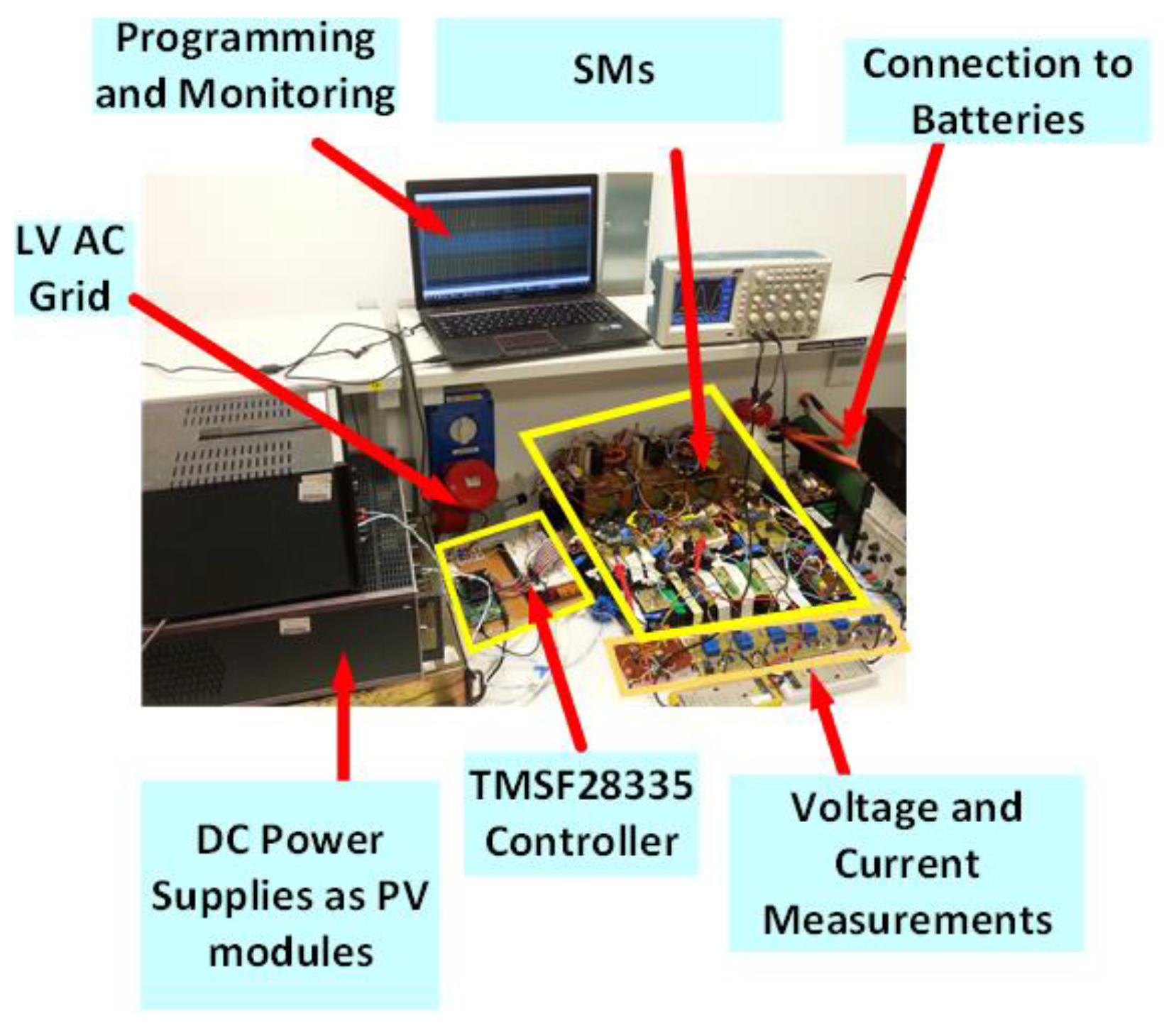
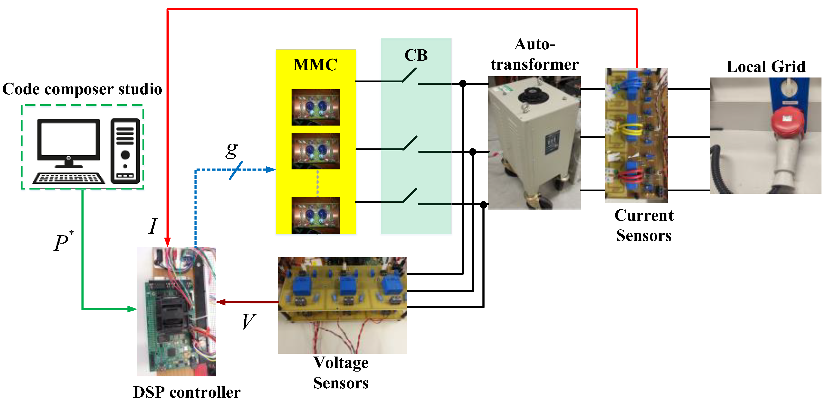
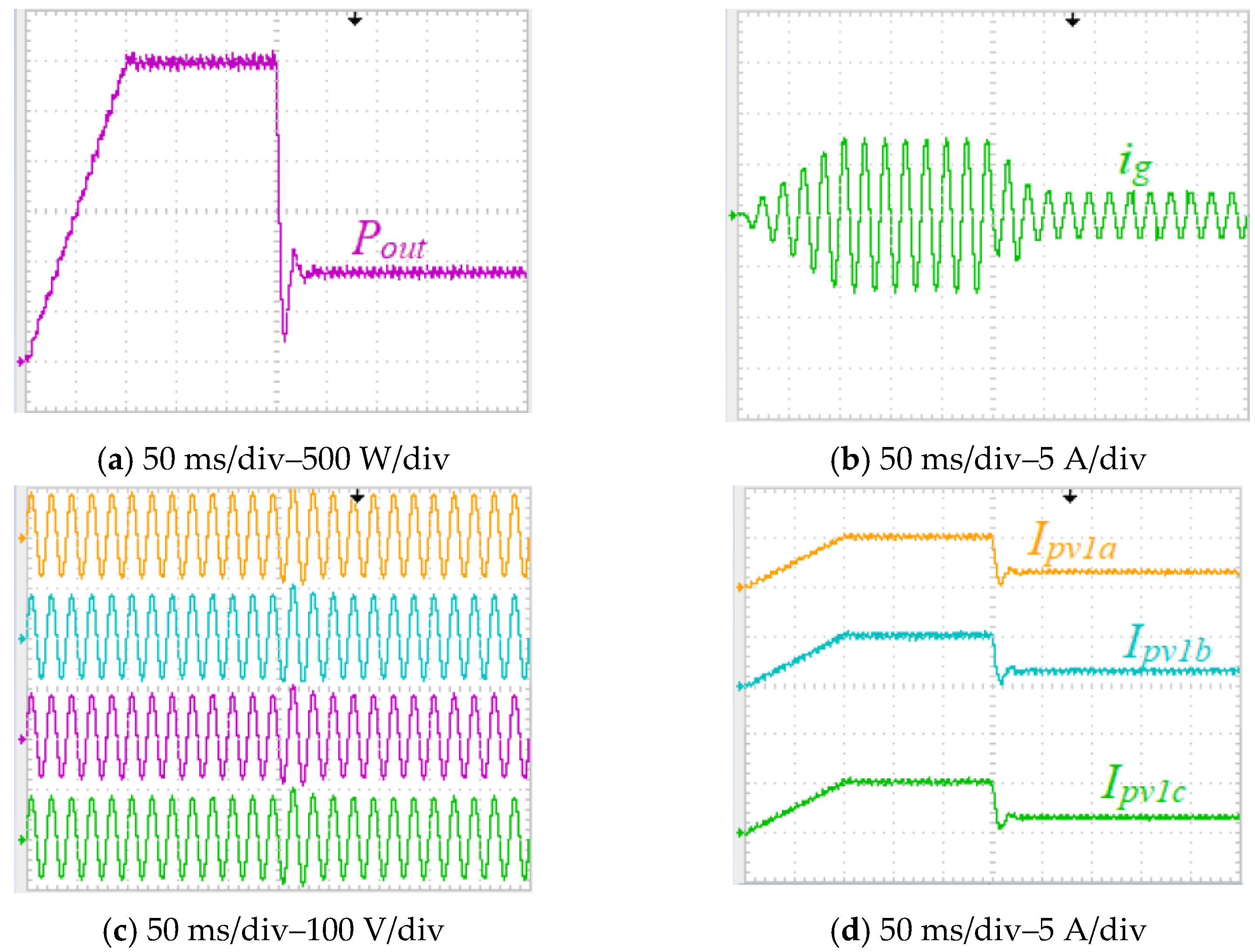
7.2. Experimental Study

The experimental setup for the three-phase implementation of the proposed MMC with 12 SMs and the block diagram of the connection of the SMs are shown in Figure 15 and Figure 16, respectively. Each SM is rated at 750 W, and hence the maximum available power from the whole system is rated at 9 kW. The parameters listed in Table 2 are used for the experiments, and a digital signal processor (DSP-TMS320f28335) is used to control the MMC. DC power supplies have been employed to mimic the PV modules. In addition, the system’s output is connected to the local grid, and its rated power (approximately 9 kW) is converted to the LV AC grid to verify the operation of the three-phase topology.
The battery pack is shown in Figure 17. Each SM is connected to a battery segment consisting of eight series lithium-ion battery cells rated at nearly 30 V. An EMUS battery management system (BMS) continuously monitors each cell’s voltage, temperature, and current through a dedicated cell module circuit that controls the battery packs to ensure safety requirements. The required data, including voltage, current, and temperature measurements of the battery segments, is sent to the central controller using a controller area network (CAN) communication bus.
Figure 18 shows how the 12 outputs of the SMs are synchronized and connected to the electricity grid. The proposed MMC is connected to the grid through an autotransformer to increase the output voltage gradually. The voltage at the point of common coupling (PCC) with the autotransformer is measured by the voltage sensing boards, and the values are sent to the DSP via the analog-to-digital (ADC). At the start, the DSP controls the switches of the MMC to generate the same voltage as the PCC, so the current is always zero, and no power flows into the electricity grid. The auto-transformer dial increases the voltage manually until the full voltage is reached. Then, the circuit breaker (CB) is closed, and the system is connected to the grid completely.
The module-level control shown in Figure 19 is applied in experiments since there might be small mismatches between the SMs, or they might even be supplied from different power supplies. The central controller generates the same duty-cycle ratios for all SMs.
The SM controller shown in Figure 20, on the other hand, will generate the small-signal duty-cycle ratios for the SMs depending on their power share. Because all SMs in each phase share the same output current, the output voltages of the kth SM (i.e., vok) will depend on the ratio of the power generated by this SM (i.e., pk) with respect to the total generated by the full system (i.e., P):
v o k = p k P v o
Experimental results during DC/AC operation are displayed in Figure 21, where the measured total output (grid) power of the MMC and the single-phase grid voltage and current are shown in Figure 21a,b, respectively. Further, the output voltages of the first four SMs in phase “a” are shown in Figure 21c. The input currents of the first SMs in the three phases are demonstrated in Figure 21d. The experimental results, in this case, are conducted to validate part of the computer simulations carried out in Figure 13.
To show the DC/DC operation mode of the SMs when the system is used to charge the battery segments through the DC voltage sources (as PV modules), the charging test has been carried out, and the results are shown in Figure 22. The input voltage and current of the first SM are depicted in Figure 22a. Further, the output current (of the first SM) charging the battery segment and the charging power are shown in Figure 22b,c, respectively.
To evaluate the stability of the proposed system, the output power Pout is first increased to 3 kW in 100 ms, then after 150 ms, it is suddenly dropped by almost 75% (to roughly 750 W). As shown in Figure 23b, the grid current ig is tracking the variations in the output power Pout, decreasing to 25% of its maximum value after 250 ms. The same is observed for the three-phase input currents of the first SM (PV currents), whilst the output voltages of the first four SMs (v1a, v2a, v3a, and v4a) remain constant.

8. Conclusions

This paper proposes a new MMC topology for PV/EV/grid integration in which isolated single-stage SEPIC-based converters are used as the SMs. The SMs can operate in DC/DC mode (the PV modules charge the batteries) and DC/AC mode (the power is fed into the AC grid by PV modules or batteries). Therefore, there is no need to add an extra DC/DC or DC/AC converter. The main benefits delivered by the isolated SEPIC-based SMs are low input ripple current, high power factor, and non-inverted flexible output voltage (higher/lower than the input voltage). High efficiency at high input voltages is the other excellent benefit of an SEPIC-based SM. They need very small input capacitances at the input side so the PV modules can operate efficiently at the maximum power point. State-space modelling of the proposed MMC topology is presented to obtain the SMs transfer functions and design the control schemes. The proper controller for each mode of operation is designed and applied to supply constant current from either the PV modules or the battery cells and ensure that the second-order harmonic current components that appear in the input voltage and current are eliminated so the PV modules and/or the battery cells can operate efficiently. Simulations using MATLAB/Simulink and experimental results using a scaled-down prototype validate the performance of the proposed MMC topology and show the feasibility of the selected control designs.

Author Contributions

Conceptualization, A.D. and A.M; methodology, F.N.E., A.D. and A.M.; software, F.N.E. and A.D.; validation, F.N.E. and A.D.; formal analysis, F.N.E., A.D. and A.M.; investigation, F.N.E., A.D. and A.M.; resources, F.N.E., A.D. and A.M.; data curation, F.N.E., A.D. and A.M.; writing-original draft preparation, F.N.E. and A.D; writing-review and editing, A.D. and A.M.; visualization, F.N.E., A.D. and A.M.; supervision, A.D.; project administration, A.D and A.M.; funding acquisition, A.D. and A.M. All authors have read and agreed to the published version of the manuscript.

Funding

This research received no external funding.

Data Availability Statement

Not applicable.

Conflicts of Interest

The authors declare no conflict of interest.

References

  1. Hu, P.; Schmitt, R.R.; Schwarzer, J.; Moore, W.H. Transportation Statistics Annual Report 2021. Available online: https://rosap.ntl.bts.gov/view/dot/59268 (accessed on 21 June 2022).
  2. Khaligh, A.; D'Antonio, M. Global trends in high-power on-board chargers for electric vehicles. IEEE Trans. Veh. Technol. 2019, 68, 3306–3324. [Google Scholar] [CrossRef]
  3. Ram, S.K.; Devassy, S.; Verma, B.K.; Mishra, S.; Akbar, S.A. Review on Renewable Energy Based EV Charging System with Grid Support Functionality. In Proceedings of the 2021 7th International Conference on Advanced Computing and Communication Systems (ICACCS), Coimbatore, India, 19–20 March 2021. [Google Scholar]
  4. Naeem, M.W.; Ahmad, J.; Adnan, M.; Ijaz, K.; Hussain, Z.; Butt, F.A. Control of Grid-tied PV Powered Charging Station for Electric Vehicles. In Proceedings of the 2021 International Conference on Innovative Computing (ICIC), Lahore, Pakistan, 9–10 November 2021. [Google Scholar]
  5. Adnan, M.; Ahmad, J.; Ali, S.F.; Imran, M. A techno-economic analysis for power generation through wind energy: A case study of Pakistan. Energy Rep. 2021, 7, 1424–1443. [Google Scholar] [CrossRef]
  6. Shemami, M.S.; Alam, M.S.; Asghar, M.J.; Shariff, S.M. Adaptive Neuro-Fuzzy Inference System (ANFIS) for Optimization of Solar Based Electric Vehicle-to-Home (V2H) Fuzzy Inference System (FIS) Controller. In Proceedings of the 2019 IEEE Transportation Electrification Conference and Expo (ITEC), Detroit, MI, USA, 19–21 June 2019. [Google Scholar]
  7. Tabari, M.; Yazdani, A. Stability of a dc distribution system for power system integration of plug-in hybrid electric vehicles. IEEE Trans. Smart Grid 2014, 5, 2564–2573. [Google Scholar] [CrossRef]
  8. Parikh, P.; Patil, S. Active and reactive power control of PV-PHEV fed 3-level Neutral Point Clamped Inverter. In Proceedings of the 2015 International Conference on Power and Advanced Control Engineering (ICPACE), Bengaluru, India, 12–14 August 2015. [Google Scholar]
  9. Rahimi, R.; Habibi, S.; Shamsi, P.; Ferdowsi, M. An Interleaved High Step-Up DC-DC Converter Based on Combination of Coupled Inductor and Built-in Transformer for Photovoltaic-Grid Electric Vehicle DC Fast Charging Systems. In Proceedings of the 2021 IEEE Texas Power and Energy Conference (TPEC), College Station, TX, USA, 2–5 February 2021. [Google Scholar]
  10. Lei, H.; Hao, R.; You, X.; Li, F. Nonisolated high step-up soft-switching DC–DC converter with interleaving and Dickson switched-capacitor techniques. IEEE J. Emerg. Sel. Top. Power Electron. 2019, 8, 2007–2021. [Google Scholar] [CrossRef]
  11. Alzahrani, A.; Ferdowsi, M.; Shamsi, P. High-voltage-gain DC–DC step-up converter with bifold Dickson voltage multiplier cells. IEEE Trans. Power Electron. 2019, 34, 9732–9742. [Google Scholar] [CrossRef]
  12. Zheng, Y.; Xie, W.; Smedley, K.M. Interleaved high step-up converter with coupled inductors. IEEE Trans. Power Electron. 2018, 34, 6478–6488. [Google Scholar] [CrossRef]
  13. Zheng, Y.; Smedley, K.M. Interleaved high step-up converter integrating coupled inductor and switched capacitor for distributed generation systems. IEEE Trans. Power Electron. 2018, 34, 7617–7628. [Google Scholar] [CrossRef]
  14. Forouzesh, M.; Shen, Y.; Yari, K.; Siwakoti, Y.P.; Blaabjerg, F. High-efficiency high step-up DC–DC converter with dual coupled inductors for grid-connected photovoltaic systems. IEEE Trans. Power Electron. 2017, 33, 5967–5982. [Google Scholar] [CrossRef]
  15. Nouri, T.; Kurdkandi, N.V.; Shaneh, M. A novel ZVS high-step-up converter with built-in transformer voltage multiplier cell. IEEE Trans. Power Electron. 2020, 35, 12871–12886. [Google Scholar] [CrossRef]
  16. Chang, Y.-N.; Cheng, H.-L.; Yen, H.-C.; Chang, C.-H.; Huang, W.-D. An interleaved DC/DC converter with soft-switching characteristic and high step-up ratio. Appl. Sci. 2020, 10, 2167. [Google Scholar] [CrossRef] [Green Version]
  17. Santos de Carvalho, M.R.; Bradaschia, F.; Rodrigues Limongi, L.; de Souza Azevedo, G.M. Modeling and control design of the symmetrical interleaved coupled-inductor-based boost DC-DC converter with clamp circuits. Energies 2019, 12, 3432. [Google Scholar] [CrossRef] [Green Version]
  18. Singh, S.A.; Williamson, S.S. Comprehensive review of PV/EV/grid integration power electronic converter topologies for DC charging applications. In Proceedings of the 2014 IEEE Transportation Electrification Conference and Expo (ITEC), Dearborn, MI, USA, 15–18 June 2018. [Google Scholar]
  19. Singh, S.A.; Carli, G.; Azeez, N.A.; Williamson, S.S. A modified Z-source converter based single phase PV/grid inter-connected DC charging converter for future transportation electrification. In Proceedings of the 2016 IEEE Energy Conversion Congress and Exposition (ECCE), Milwaukee, WI, USA, 18–22 September 2016. [Google Scholar]
  20. Niroomand, M.; Nasr Esfahani, F. Converter Technologies for PV Systems: A Comprehensive Review. In Energy Conversion Systems, Energy Science, Engineering and Technology; Tripathi, S.M., Padmanaban, S., Eds.; Nova Science Publishers: Hauppauge, NY, USA, 2021; pp. 1–58. [Google Scholar]
  21. Alotaibi, S.; Darwish, A. Modular Multilevel Converters for Large-Scale Grid-Connected Photovoltaic Systems: A Review. Energies 2021, 14, 6213. [Google Scholar] [CrossRef]
  22. Gontijo, G.; Wang, S.; Kerekes, T.; Teodorescu, R. Performance Analysis of Modular Multilevel Converter and Modular Multilevel Series Converter under Variable-Frequency Operation Regarding Submodule-Capacitor Voltage Ripple. Energies 2021, 14, 776. [Google Scholar] [CrossRef]
  23. Darwish, A.; Abdelsalam, A.K.; Massoud, A.M.; Ahmed, S. Single phase grid connected current source inverter: Mitigation of oscillating power effect on the grid current. In Proceedings of the IET Conference on Renewable Power Generation (RPG 2011), Edinburgh, Scotland, 6–8 September 2011. [Google Scholar]
  24. Leon, J.I.; Vazquez, S.; Franquelo, L.G. Multilevel converters: Control and modulation techniques for their operation and industrial applications. Proc. IEEE 2017, 105, 2066–2081. [Google Scholar] [CrossRef]
  25. Yildirim, M.A.; Nowak-Ocłoń, M. Modified Maximum Power Point Tracking Algorithm under Time-Varying Solar Irradiation. Energies 2020, 13, 6722. [Google Scholar] [CrossRef]
  26. Tobón, A.; Peláez-Restrepo, J.; Villegas-Ceballos, J.P.; Serna-Garcés, S.I.; Herrera, J.; Ibeas, A. Maximum Power Point Tracking of Photovoltaic Panels by Using Improved Pattern Search Methods. Energies 2017, 10, 1316. [Google Scholar] [CrossRef] [Green Version]
  27. Darwish, A.; Elgenedy, M.A. Current-source modular medium-voltage grid-connected system with high-frequency isolation for photovoltaic applications. IEEE Trans. Energy Convers. 2018, 34, 255–266. [Google Scholar] [CrossRef] [Green Version]
  28. Badawy, A.D. Current Source dc-dc and dc-ac Converters with Continuous Energy Flow. Ph.D. Thesis, University of Strathclyde, Glasgow, UK, 2015. [Google Scholar]
  29. Polsky, T.; Horen, Y.; Bronshtein, S.; Baimel, D. Transient and Steady-State Analysis of a SEPIC Converter by an Average State-Space Modelling. In Proceedings of the 2018 IEEE 18th International Power Electronics and Motion Control Conference (PEMC), Budapest, Hungary, 26–30 August 2018. [Google Scholar]
  30. Niroomand, M.; Nasr Esfahani, F. Control Structures of Grid-Tied Photovoltaic Systems. In Energy Conversion Systems, Energy Science, Engineering and Technology; Tripathi, S.M., Padmanaban, S., Eds.; Nova Science Publishers: Hauppauge, NY, USA, 2021; pp. 59–133. [Google Scholar]
Figure 1. Modular grid-connected MMC topology with EES. (a) Single-phase layout. (b) Three-phase layout. (c) Single-stage SEPIC-based SM.
Energies 15 05462 g001
Figure 2. SM equipped with SPDT relays for different operation modes.
Energies 15 05462 g002
Figure 3. SPDT relays connections. (a) DC/AC (from PV to the AC grid). (b) DC/AC (from battery to the AC grid).
Energies 15 05462 g003
Figure 4. SM waveforms during DC/AC conversion.
Energies 15 05462 g004
Figure 5. SEPIC-based SM as a DC/AC inverter for the positive half-cycle (vg >0): (a) Subinterval 1 (0 ≤ t < ton1). (b) Subinterval 2 (ton1 ≤ t < ton1+ ton2). (c) Subinterval 3 (ton1+ ton2t < ts). (d) Key output waveforms (with D = d1 + d2).
Energies 15 05462 g005
Figure 6. SPDT relays connections in the DC/DC mode (from the PV modules to the battery packs).
Energies 15 05462 g006
Figure 7. SEPIC-based SM as a DC/DC converter: (a) Subinterval 1 (0 ≤ t < ton). (b) Subinterval 2 (tont < ts). (c) Key output waveforms.
Energies 15 05462 g007aEnergies 15 05462 g007b
Figure 8. SM controller during DC/AC conversion from PV modules to the AC grid: (a) block diagram. (b) Hysteresis band (dcl: closed-loop control duty-cycle ratio; dff: feedforward duty-cycle ratio).
Energies 15 05462 g008
Figure 9. SM controller during DC/AC conversion from batteries to the AC grid (dcl: closed-loop control duty-cycle ratio; dff: feedforward duty-cycle ratio).
Energies 15 05462 g009
Figure 10. Pole-zero maps of the output-loop controller: (a) kp = 1 and kr = [1:10], and (b) kr = 1 and kp = [0.1:2].
Energies 15 05462 g010
Figure 11. SM controller during DC/DC conversion from PV modules to batteries.
Energies 15 05462 g011
Figure 12. SIMULINK/MATLAB simulations of the proposed MMC for DC/AC conversion: (a) total output (grid) power; (b) grid voltage and current; (c) output voltage of SM1; (d) PV arrays current (input current) of SM1.
Energies 15 05462 g012
Figure 13. SIMULINK/MATLAB simulations during DC/AC inversion from batteries to the grid: (a) total output (grid) power; (b) single-phase grid voltage and current (c) output voltage of SM1. (d) Battery packs’ current of SM1.
Energies 15 05462 g013
Figure 14. SIMULINK/MATLAB simulations during DC/DC battery charging. (a) PV arrays voltage of SM1. (b) PV arrays current of SM1. (c) Battery current. (d) Charging power.
Energies 15 05462 g014
Figure 15. Experimental setup of the proposed MMC with 12 SMs.
Energies 15 05462 g015
Figure 16. The block diagram of the connection of the SMs in experiments.
Energies 15 05462 g016
Figure 17. Battery segments consisting of 8 series lithium-ion battery cells together with a CAN communication bus.
Energies 15 05462 g017
Figure 18. Grid-connection steps.
Energies 15 05462 g018
Figure 19. Central controller in the experiments (per phase).
Energies 15 05462 g019
Figure 20. SM’s control system in the experiments.
Energies 15 05462 g020
Figure 21. Experimental results during DC/AC inversion from DC sources to the grid. (a) Total output (grid) power; (b) single-phase grid voltage and current; (c) output voltage of the first four SMs; (d) first SM’s input current (PV current).
Energies 15 05462 g021
Figure 22. Experimental results during DC/DC operation mode from DC sources to the grid. (a) PV voltage and current of the first SM; (b) SM1′s (battery’s) output current; (c) charging power.
Energies 15 05462 g022
Figure 23. Experimental results during sudden 75% drop in power. (a) Total output (grid) power; (b) single-phase grid voltage and current; (c) output voltage of the first four SMs; (d) first SM’s input current (PV current).
Energies 15 05462 g023
Table 1. Parameters of the SIMULINK/MATLAB model.
ParametersValue
Number of modulesn = 80
SM rated powerPSM = 4.2 kW
SM inductorsL1 = 0.5 mH
L2 = 10 mH
SM capacitorsC1 = C2 = 10 μF and Co = 1 μF
SM Switching frequencyfs = 50 kHz
Transformer turns’ ratioN = 1
PV moduleGrape Solar GS-S-420-KR3
(Pm = 420 W, Vmp = 48.73 V, Imp = 8.62)
PV array10 parallel × 1 series
Battery pack voltageVbat = 200 V
Grid line-to-line voltageVO(rms) = 24.5 kV
Grid impedanceLg = 1 mH, rg = 0.5 Ω
Grid frequencyf = 50 Hz
Table 2. Parameters of the experimental setup.
ParametersValue
Number of modulesn = 4
SM rated powerPSM = 750 W
SM inductorsL1 = 1 mH
L2 = 10 mH
SM capacitorsC1 = C2 = 10 μF and Co = 1 μF
SM switching frequencyfs = 20 kHz
Transformer turns’ ratioN = 1
DC suppliesKeysight N8761A
Sorensen SGI 100/150
Battery pack voltageVbat = 200 V
Grid phase voltage230 VAC
Grid impedanceLg = 1 mH, rg = 0.5 Ω
Grid frequencyf = 50 Hz
Battery pack voltageVbat = 200 V
Grid phase voltage230 VAC
Publisher’s Note: MDPI stays neutral with regard to jurisdictional claims in published maps and institutional affiliations.

