Article

Improving Fuel Properties and Hydrocarbon Content from Residual Fat Pyrolysis Vapors over Activated Red Mud Pellets in Two-Stage Reactor: Optimization of Reaction Time and Catalyst Content

by
Caio Campos Ferreira
1,
Lucas Pinto Bernar
1,
Augusto Fernando de Freitas Costa
1,
Haroldo Jorge da Silva Ribeiro
1,
Marcelo Costa Santos
1,
Nathalia Lobato Moraes
2,
Yasmin Santos Costa
2,
Ana Cláudia Fonseca Baia
2,
Neyson Martins Mendonça
2,
Sílvio Alex Pereira da Mota
3,
Fernanda Paula da Costa Assunção
4,
Douglas Alberto Rocha de Castro
5,
Carlos Castro Vieira Quaresma
5,
Sergio Duvoisin, Jr.
6,
Luiz Eduardo Pizarro Borges
7 and
Nélio Teixeira Machado
1,2,*
1
Graduate Program of Natural Resources Engineering of Amazon, Campus Profissional-UFPA, Universidade Federal do Pará, Rua Augusto Corrêa N° 1, Belém 66075-110, Brazil
2
Faculty of Sanitary and Environmental Engineering, Campus Profissional-UFPA, Universidade Federal do Pará, Rua Corrêa N° 1, Belém 66075-900, Brazil
3
Graduate Program of Chemistry, Universidade Federal do Sul e Sudeste do Pará, Folha 31, Quadra 7, Lote Especial-Nova Marabá, CEP, Marabá 68507-590, Brazil
4
Graduate Program of Civil Engineering, Campus Profissional-UFPA, Universidade Federal do Pará, Rua Augusto Corrêa N° 1, Belém 66075-110, Brazil
5
Centro Universitário Luterano de Manaus–CEULM/ULBRA, Avenida Carlos Drummond de Andrade N°. 1460, Manaus 69077-730, Brazil
6
Faculty of Chemical Engineering, Universidade do Estado do Amazonas-UEA, Avenida Darcy Vargas N°. 1200, Manaus 69050-020, Brazil
7
Laboratory of Catalyst Preparation and Catalytic Cracking, Section of Chemical Engineering, Instituto Militar de Engenharia-IME, Praça General Tibúrcio N°. 80, Rio de Janeiro 22290-270, Brazil
*
Author to whom correspondence should be addressed.
Energies 2022, 15(15), 5595; https://doi.org/10.3390/en15155595
Submission received: 16 June 2022 / Revised: 14 July 2022 / Accepted: 27 July 2022 / Published: 2 August 2022
(This article belongs to the Special Issue Advances in Biodiesel for Application in Diesel Engines)

Abstract

:
Catalytic upgrading of vapors from pyrolysis of triglycerides materials is a promising approach to achieve better conversions of hydrocarbons and production of liquid biofuels. Catalytic cracking often shows incomplete conversion due to distillation of initial reaction products and the addition of a second catalytic reactor, whereas pyrolytic vapors are made in contact to a solid catalyst was applied to improve the physical-chemical properties and quality of bio-oil. This work investigated the effect of catalyst content and reaction time by catalytic upgrading from pyrolysis vapors of residual fat at 450 °C and 1.0 atmosphere, on the yields of reaction products, physicochemical properties (density, kinematic viscosity, refractive index, and acid value), and chemical composition of organic liquid products (OLP), over a catalyst fixed bed reactor, in semi pilot scale. Pellets of red mud chemically activated with 1.0 M HCl were used as catalysts. The thermal catalytic cracking of residual fat show OLP yields from 54.4 to 84.88 (wt.%), aqueous phase yields between 2.21 and 2.80 (wt.%), solid phase yields (coke) between 1.30 and 8.60 (wt.%), and gas yields from 11.61 to 34.22 (wt.%). The yields of OLP increases with catalyst content while those of aqueous, gaseous and solid phase decreases. For all experiments, the density, kinematic viscosity, and acid value of OLP decreases with reaction time. The GC-MS of liquid reaction products identified the presence of hydrocarbons and oxygenates. In addition, the hydrocarbon content in OLP increases with reaction time, while those of oxygenates decrease, reaching concentrations of hydrocarbons up to 95.35% (area.). The best results for the physicochemical properties and the maximum hydrocarbon content in OLP were obtained at 450 °C and 1.0 atmosphere, using a catalyst fixed bed reactor, with 5.0% (wt.) red mud pellets activated with 1.0 M HCl as catalyst.

1. Introduction

Catalytic upgrading of coal and biomass pyrolysis volatiles and/or vapors is one of potential processes to improve the quality of bio-oils, not only by converting volatile substances into valuable chemicals, particularly light aromatic hydrocarbons, but also upgrading transport (kinematic viscosity) and physical-chemistry properties (acidity, corrosivity, oxidative stability, etc.) of bio-oils [1,2,3,4,5,6,7,8,9,10,11,12,13,14,15,16,17,18,19,20,21,22,23,24,25,26,27,28,29,30,31,32,33,34,35]. Catalytic upgrading research focused on volatiles/vapors of Lignocelullosic biomass including poplar wood [1], walnut shell [7], rape straw [8,12,16,19], Yunnan pine [10], rice husk [13], beech wood [14,18], Canadian white pine wood-ships [17], Southern yellow pine [21,22], lignocellulosic material [24], sugarcane bagasse [25], alkali lignin [28], corn Stover [29], cellulose [30,34], lignin [30], pine sawdust [31], pyrolysis volatiles of coal/lignite (including Pingshuo bituminous coal) [2,32], Baiyinhua lignite [3,11], Shengli lignite [4,6], Fenxi bituminous coal [5], Bai Yinhua lignite [23], Shendong long-flame coal [23], Xinwen gas coal [23], Luliang coking coal [23], Anyang anthracite coal [23], Fucheng coal [32], Hexi coal [32], pyrolysis volatiles/vapors of lipid-base materials (including castor seed oil) [9], Jatropha waste [15], residual fat [35], and even pyrolysis volatiles/vapors of monosaccharides (glucose) [30] and waste tires granules [26]. The state of art, progress, and new trends on catalytic upgrading of pyrolysis volatiles from coal, biomass, lipid-material, and other materials (glucose, waste tires granules, etc.) were described in detail in the excellent reviews by Ren et al. [20], Nishu et al. [27], and Asadieraghi et al. [33].
Even though lignocellulosic materials are available in large quantities over the world and constitute an important class of feedstock for production of economically viable biofuels [36], there are technical difficulties when the production of drop in biofuels is considered. The organic liquid fraction yields are usually low for typical process variables used for catalytic upgrading, around 15 to 20% [7,8,10,12,14,16,18,19,30]. Moreover, the bio-oil composition is significantly different than conventional transport fuels with high amounts of aromatic compounds such as phenols and other oxygenated compounds like aldehydes, carboxylic acids and ketones even after the upgrading process [13,14,17,18,22,24,25,29,30] increasing processing costs in the form of purifications and/or other transformation processes. Similar problems arise for the catalytic upgrading of coal [3,4,11,23,32]. The catalytic cracking of lipid-based materials (triglycerides) shows higher amounts of liquid fraction composed of straight chain hydrocarbons as alkanes and alkenes due to molecular structure of triglycerides and fatty acids [37,38,39,40,41,42]. The problem for application of pyrolytic oils as fuels reside in the presence of oxygenated compounds, such as carboxylic acids, aldehydes, and ketones, that need to be separated, reducing yield and increasing costs. In order to reduce that need, complete conversion of fatty acids, aldehydes, and ketones to hydrocarbons is expected on the catalytic cracking process, but this goal is hard to achieve due to distillation of initial products formed in the reaction in atmospheric pressure [43]. The inclusion of a second catalytic cracking step in the vapor phase (upgrading) is one way to avoid high pressure reactions, leading to investment and safety issues.
Among the various catalysts used for the catalytic upgrade of pyrolysis volatiles from coal, biomass, lipid-material, and other materials (glucose, waste tires granules, etc.), the most used were HZSM-5 [2,3,4,6,7,8,10,11,12,15,16,19,23,25,30,31], ZSM-5 [10,13,14,16,22,26,28,29,34], Y-zeolite [5,26,32], β-zeolite [21], faujasite-zeolite [17], mesoporous aluminosilicates [18], and clay mineral (Kaolin) [9], activated carbon [35], as well as oxide-base catalysts [1,9,14,24], as summarized in Table 1.
Red mud is the largest waste produced on the refining process of bauxite into alumina and it was demonstrated recently to be a cheap catalyst for the upgrading of fat, oils, and grease (FOG) from grease traps into hydrocarbons fractions [44,45,46].
All studies on catalytic upgrade of pyrolysis volatiles have been focused on deoxygenation of bio-oil oils [1,2,3,4,5,6,7,8,9,10,11,12,13,14,15,16,17,18,19,20,21,22,23,24,25,26,27,28,29,30,31,32,33,34,35], but conversion to aromatics was also investigated [3,5,6,10,11,13,15,28,29,30,32,35], as well as reaction mechanism/pathway [3,4,6,7,8,10,11,19,23,24,30]. Catalytic upgrading was studied by flash/analytical pyrolysis (Py–GC/MS) [1,2,5,15,21,22,24,32], by flash pyrolysis [3,4,6,11,34], as well as by vacuum pyrolysis [8,12,16,19], in drop-tube reactors [3,4,6,11,23,30], fixed bed reactors [7,8,9,10,13,25,26,31,35], and fluidized bed reactors [31]. The catalytic upgrade of pyrolysis volatiles was performed in micro [1,2,5,15,21,22,24,32], bench [18], laboratory [3,4,6,7,8,9,10,11,12,13,14,16,17,19,23,25,26,28,29,30,31,34], and semi-pilot [35]. The catalytic upgrade processes were operated in batch [7,8,9,10,12,13,14,16,17,21,25,26,28,29,35] and continuous mode [1,3,4,6,11,23,30,31], and only few studies conducted experiments operating as a two-stage reactor, one for the thermal cracking and vaporization of feedstock and other for the catalytic upgrading on vapor phase [8,12,13,16,17,19,26,31,35].
Products of reactions from lignocelullosic biomass [1,7,8,10,12,13,14,16,17,18,19,21,22,24,25,29,31], lignin [28,30], cellulose [30,34], coal/lignite [2,3,4,5,6,11,23,32], lipid-base materials [9,15,35], monosaccharides (glucose) [30], and waste tires granules [26] include hydrocarbons (gas and liquid), water, oxygenated compounds, and coke. The physicochemical properties investigated includes viscosity [8,9,12,16,17,19,35], specific heat [9], high heating value [8,10,12,16,17,19], cloud point [9], density [8,12,16,19,35], water content [8,9,10,17], and pH [8,9,12,16,17,19].
Process variables affecting the yield and quality of bio-oil are temperature [2,4,6,8,9,11,24,28,31,35], catalyst-to-biomass ratio (C/F) [8,9,15,25,28,29,35], characteristics of feed material [2,3,4,5,6,11,23,32], gas flow rate [31], weight hour space velocity (WHSV) [31], and the process scale [8,9,15,25,28,29]. The modes of operation used (batch, continuous, semi-continuous), pyrolysis type (flash/analytical, flash, slow and vacuum), and reactors used (drop-tube, fixed and fluidized beds) can also affect yield and composition of liquid product.
Research on the effect of C/F ratio on the yield and quality of bio-oil obtained by catalytic upgrading was conducted in micro [15] laboratory [8,9,25,28,29], and semi-pilot scales [35]. Until now, though, there is no study of the effect of C/F ratio and reaction time on yields and quality (physicochemical characteristics and compositional analysis) of bio-oil obtained from the pyrolysis of waste triglycerides using red mud as catalyst in a two-stage reactor in semi-pilot scale [35]. The effect of catalyst-to-biomass ratio on the yield and chemical composition of bio-oil pyrolysis by catalytic upgrade of pyrolysis vapors [8,9,15,19,25,28,29], summarized as follows.
Fan et al. [8], investigated influence of process parameters (temperature, C/F ratio, catalyst Si/Al ratio) on the yield and composition of liquid phase by the catalytic upgrading of vapors from the vacuum pyrolysis of rape straw over nanocrystalline HZSM-5, on a two-stage reactor in laboratory scale. The fixed bed pyrolysis reactor (φid = 60 mm, H = 150 cm, VReactor = 4241 mL), placed below the catalytic reactor, was coupled to a catalytic reactor (φid = 40 mm, H = 100 mm, VReactor = 125.6 mL). Experiments were carried out at 400, 450, 500, 550, and 600 °C, biomass-to-catalyst ratios of 1.0, 0.5, 1/3, 0.25, and 0.2, HZSM-5 Si/Al ratios of 25, 50, 75, and 100, using particles of rape straw within the range of 100–150 μm. For the experiments with varying temperature, catalyst-to-biomass ratio of 3, and HZSM-5 Si/Al ratio of 50, the yield of liquid phase varied between 33.24 and 42.65% (wt.), showing a decrease with increasing temperature. For the experiments with varying biomass-to-catalyst ratio, 500 °C, and HZSM-5 Si/Al ratio of 50, the yield of liquid phase varied between 29.24 and 43.15% (wt.), showing a decrease with increasing catalyst-to-biomass ratio. For the experiments with varying HZSM-5 Si/Al ratio, 500 °C, and catalyst-to-biomass ratio, the yield of liquid phase varied between 29.24 and 43.15% (wt.), showing an increase with increasing HZSM-5 Si/Al ratio. The optimize operating conditions were 500 °C, HZSM-5 Si/Al ratio of 50, and catalyst-to-biomass ratio of 3. The pH, density, and viscosity of bio-oil were 5.15, 0.96 (g/cm3), and 5.12 (mm2/s), respectively. The GC-MS analysis shows that catalytic upgrading of pyrolytic vapors from the vacuum pyrolysis of rape straw increases substantially the content of aromatics and hydrocarbons, while those of phenols decrease.
Li et al. [19] investigated the effects of mixing ratios catalysts (HZSM-5, MCM-41) in different proportions using in situ catalytic in the upgrading of biomass-derived pyrolysis vapors of rape straw, on a two-stage reactor in lab scale. The fixed bed pyrolysis reactor (φid = 60 mm, H = 150 cm, VReactor = 4241 mL), placed below the catalytic reactor, was coupled to a catalytic reactor (φid = 42 mm, H = 116 mm, VReactor = 160.7 mL). The experiments carried out at 500 °C using different mixing ratios HZSM-5, 90%HZSM-5/10%MCM-41, 70%HZSM-5/30%MCM-41, 50%HZSM-5/50%MCM-41, 30%HZSM-5/70%MCM-41, 10%HZSM-5/90%MCM-41, and MCM-41. The experimental results show that increasing the MCM-41 proportion causes decrease on the yield of bio-oil from 23.0 to 17.61% (wt.) until the mixing ratio proportion of 50%, whereas an increase on bio-oil yield from 17.61 to approximately 26.0% (wt.) is observed for mixing ratio proportion higher than 50% (wt.). The physicochemical properties using mixing ratios 50%HZSM-5/50%MCM-41 gives the best results. That way, the pH, density, and viscosity of bio-oil were 5.4, 0.94 (g/cm3), and 5.06 (mm2/s), respectively. The GC/MS analysis shows that hydrocarbon content in the bio-oil organic phase gradually increased and the carbonyl groups content gradually decreased as the MCM-41 content increased from 0 to 50%. In contrast, the hydrocarbon content gradually decreased and the carbonyl groups content gradually increased as the MCM-41 content increased from 50% to 100%. The GC/MS analysis identified aromatic hydrocarbons, as well as oxygenates including phenols, ketones, aldehydes, carboxylic acids, and alcohols.
Koul et al. [9] investigated the C/F effect on the yield of bio-oil of vapors from castor seed oil over oxide-based catalysts (kaolin, CaO, and ZnO). Physicochemical characteristics were determined for the experiment giving best yields. Experiments were conducted at 550 °C, heating rate of 25 °C/min and 0.05-0.20 C/F. Results show that the highest bio-oil yields were obtained using 15% (wt.) Kaolin, 15% (wt.) CaO, and 10% (wt.) ZnO. The highest bio-oil yields were 64.9, 66.4, and 65.8% (wt.) using Kaolin, CaO, and ZnO, respectively, showing pH values of 8.36, 9.25, and 8.32, while the measured kinematic viscosities were 39.0, 8.3, and 28.0 (mm2/s). The GC-MS analysis of bio-oils identified the presence of aromatics, esters, amines, acids, alkanes, amides, alkenes, alcohols, and ethers, as well as non-identified compounds, showing hydrocarbons contents (aromatics, alkanes, alkenes) of 21.92 (area.%), 12.43 (area.%), and 37.49 (area.%), respectively.
Vichaphund et al. [15] investigated influence of C/F ratio on the yield and quality of PLO phase obtained on the catalytic upgrading of Jatropha waste vapors over HZSM-5 impregnated with Co and Ni using flash pyrolysis/analytical pyrolysis (Py-CG/MS). The experiments were carried out at 500 °C, 30 s, using HZSM-5, Co/HZSM-5, and Ni/HZSM-5, and C/F ratios of 1.0, 5.0, and 10.0. The experiments revealed decreasing yields for increasing C/F ratio. The GC-MS analysis showed that hydrocarbon concentration increases drastically with increasing C/F. The highest yield of bio-oil was obtained over Ni/HZSM-5, C/F ratio of 1:1, being approximately to 53.0% (wt.).
Balasundram et al. [25] investigated C/F ratio on the yield and hydrocarbons composition of bio-oil in the catalytic upgrading of sugarcane bagasse pyrolysis vapors over Cerium (Ce) loaded HZSM-5, using a tubular furnace reactor in laboratory scale. The experiments were carried out at 500 °C, with catalyst-to-biomass ratios of 0.5, 1.0, 1.5, and 2.0 of HZSM-5 and Ce/HZSM-5, using dried, ground, and sieved sugarcane bagasse particle of less than 0.5 mm. The results show that the yield of pyrolysis oil is higher using (Ce) loaded HZSM-5. In addition, the yields of pyrolysis oil varied between 58.0% and 68.0% (wt.). For the experiments using (Ce) loaded HZSM-5, the yield of pyrolysis oil increases with increasing C/F ratio between 58.0% and 68.0% (wt.). The hydrocarbons content in pyrolysis bio-oil is higher using HZSM-5 compared to (Ce) loaded HZSM-5. In addition, for the experiments using HZSM-5, the hydrocarbons content in pyrolysis bio-oil increases with increasing HZSM-5-to-biomass ratio. The GC-MS analysis identified hydrocarbons and oxygenates (esters, ethers, anhydro sugars, phenols, furans, ketones, alcohols, and carboxylic acids).
Fan et al. [28] investigated the influence of process temperature and C/F ratio on the yield and quality of pyrolysis oil in the catalytic upgrading of vapors from microwave-assisted vacuum pyrolysis of lignin over HZSM-5, in laboratory scale. The experiments were carried out at 450 °C, catalyst-to-lignin ratios of 0, 0.1, 0.2, 0.3, 0.4, and 250, 350, and 550 °C, catalyst-to-lignin ratios of 0.3. For the experiments with varying catalyst-to-lignin ratios, the yield of pyrolysis bio-oil varied between 34.11 and 21.75% (wt.), showing a decrease with increasing catalyst-to-lignin ratios. In addition, the content of polycyclic aromatic hydrocarbons and monocyclic aromatic hydrocarbons increases with increasing catalyst-to-lignin ratios. For the experiments with varying temperature, the yield of pyrolysis bio-oil varied between 28.11 and 23.30% (wt.), showing no variation between 250 and 350 °C and a decrease between 350 and 550 °C. In addition, the content of polycyclic aromatic hydrocarbons increases with increasing temperature, while the content monocyclic aromatic hydrocarbons increases between 250 and 450 °C, decreasing between 450 and 550 °C. The GC-MS analysis identified polycyclic aromatic hydrocarbons (PAHs), monocyclic aromatic hydrocarbons (MAHs), and oxygenates (phenols, carboxylic acids, aldehydes, and ketones).
Zhou et al. [29] investigated the influence of two different ex-situ configurations with randomly packed bed and composite catalysts bed, as well as the effect of catalyst-to-biomass ratio for ex-situ composite catalysts bed on the yield and chemical composition of pyrolysis oil, expressed in peak area, by the catalytic upgrading of vapors from microwave-assisted vacuum pyrolysis of corn stover over silicon carbide foam supported ZSM-5, in laboratory scale. The experiments were carried out by setting the pyrolysis reactor temperature and catalyst bed temperature at 550 °C and 425 °C, respectively. For the ex-situ configurations experiments with randomly packed bed and composite catalysts bed, pyrolysis reactor temperature and catalyst bed temperature at 550 °C and 425 °C, and catalyst-to-biomass ratio of 0.25, the yield of pyrolysis bio-oil is higher for the ex-situ configurations with composite catalysts bed. In addition, the ex-situ composite catalyst bed configuration produced a pyrolysis bio-oil of higher quality, showing 41.5% (area.) aromatics and only 1.6% (area.) oxygen-containing aliphatic, while the ex-situ with randomly packed bed produced pyrolysis bio-oil containing 27.8% (area.) aromatics and 11.7% (area.) oxygen-containing aliphatic. For the ex-situ configurations experiments with composite catalysts bed, pyrolysis reactor temperature and catalyst bed temperature at 550 °C and 425 °C, and catalyst-to-biomass ratio of 0, 0.1, 0.25, and 0.5, the yield of pyrolysis bio-oil varied between 41.0 to 33.0% (wt.), decreasing with increasing catalyst-to-biomass ratio. In addition, the content of aromatic hydrocarbons and BTEX in pyrolysis bio-oil increases with increasing catalyst-to-biomass ratio. The Py-GC-MS analysis identified aliphatic hydrocarbons, aromatic hydrocarbons, polycyclic aromatic hydrocarbons (PAHs), BTEX, and oxygenates (furans, carboxylic acids, and phenols).
The objective of this work is to investigate the effect of C/F ratio (0.05, 0.075, 0.100) and reaction time (40, 50, 60, 70, and 80 min) in the catalytic upgrading of residual fat vapors using temperature of 450 °C and 1.0 atmosphere, on yield, physicochemical parameters (density, kinematic viscosity, refractive index and acid value) and chemical composition of hydrocarbons (alkanes, alkenes, and aromatics) and oxygenates (carboxylic acids, esters, ketones, and aldehydes) of pyrolysis bio-oils, over a two-stage process consisting of a thermal pyrolysis step followed by catalytic upgrading in a fixed bed reactor containing 0.0, 5.0, 7.5, and 10.0% (wt.) red mud pellets activated with 1.0 M HCl, in semi-pilot scale.

2. Materials and Methods

2.1. Materials

The residual fat was obtained from a grease trap system at University Restaurant of UFPA. The residual fat was pre-treated as described elsewhere [44]. A brief description of the pre-treating process follows. The fat was heated with mixing to remove excess moisture and obtain a homogenous material. Afterwards, the fat was filtered to remove suspended solids, as described in Figure 1 flowsheet. Red mud was obtained from a Bayer process alumina production plant of Norsk Hydro located at state of Pará and it was subjected to drying, milling, and sieving to achieve small particle sizes suitable to pellet formation.

2.2. Apparatus

Figure 2 and Figure 3 shows the experimental apparatus and schematic diagram of semi-pilot scale catalytic cracking unit mounted on a mobile metal structure (Implantação Ltda, Rio de Janeiro, Brazil. Laboratory of Catalysis Preparation and Catalytic Cracking-IME/RJ). The unit consists of a stainless steel (AISI 304) tubular reactor (ID = 8.5 cm, L = 35.5 cm, VOperational ≈ 1.5 L), inserted inside a thermal blanket of 3.5 kW, a mechanical agitation system, coupled to the reactor. The agitation system constructed by a turbine type impeller with 04 blades at 45◦ and 0.06 kW power, internal impeller diameter of 8.0 cm and maximum angular velocity of 800 rpm. A second reactor (R-2) consisting of a stainless steel (AISI 304) tube with 30 cm height and 15 mm internal diameter (V(R-2) = 53 mL) is coupled to thermal reactor (R-1). Both reactors are isolated with glass wool and their temperature measured with type K thermocouples.
The reactors (PMax = 10 bar, TMax = 550 °C), coupled to a stainless-steel double pipe condenser of ½’ nominal diameter with a heat transfer area of 500 cm2, designed to operate on the shell side (cooling water) (PMax = 10 bar, TMax = 550 °C), and on the tube side (gaseous reaction products) (PMax = 10 bar, TMax = 550 ◦C). The cooling system, a thermostatic bath with digital temperature control and recirculation, provided cool water at 10 °C. The condensates (OLP + aqueous phase) were collected inside a stainless-steel collection vessel of 2 L (PMax = 1.0 bar, TMax = 100 °C), being the operation temperature that of environment. A digital control unit controls the reactor temperature, the frequency inverter (mechanical impeller rpm), and the heating rate. The digital control unit also displays the condenser inlet and outlet temperatures.

2.3. Methodology

The process flow sheet shown in Figure 1 summarizes the applied methodology to produce upgraded bio-oil from the triglyceride waste material. The residual fat is collected and pre-treated (mixing, evaporation and filtration). The red mud is dried, milled, and sieved to reduce the particle size. Afterwards, it is activated with HCl and the pellets formed by pressing and drying followed by thermal activation. The experiments were carried out using a two-stage process of thermal pyrolysis followed by vapor-phase cracking in a catalyst fixed bed reactor, with and without catalyst. The effect of catalyst content and reaction time was analyzed. The physical-chemistry properties and chemical composition of hydrocarbon rich liquid mixtures determined.

2.3.1. Production of Red Mud Activated Pellets

Pellets of red mud, chemically activated with 1.0 M HCl, were used as catalysts, and the procedures described in detail in flowsheet illustrated in Figure 1.
The physical pre-treatment of red mud takes place in several steps, as illustrated in Figure 1. In this sense, a more detailed description of each pre-treatment step (drying, milling, and sieving) is highlighted for a better understanding as follows. First, the red mud was dried using an oven (7lab EQUIPAMENTOS E SERVICOS EIRELI ME, Rio de Janeiro-Brazil, Model: Bio SEA—40L) for a period of eight hours, at a temperature of 105 °C, to remove the excess water. An amount of 1000 g of red mud was used each batch. The material was weighed every hour to compute the drying curve. Afterwards, the dried red mud was ground using a ball mill (Brand: CIMAQS, Series N°. 005) in order to reduce the particle size. An amount of 5.5 kg of dried red mud was processed by each grinding/milling batch for 1 h. Then, the dried and ground red mud was submitted to sieving to select/classify only particles with particle size smaller than 65 MESH sieve (0.210 mm). A total of 25 sieving batches were carried out. Red mud before and after the pre-treating of drying, milling, and sieving is shown in Figure 4. Figure 4a–d illustrate a sequence of steps to produce pellets of uniform density and shape, showing it is necessary to use particles of smaller sizes. Moreover, the pellets produced with larger particle sizes tend to crumble and break, making the process of shaping the pellets much difficult.

2.3.2. Chemical Activation of Red Mud

After the physical pre-treatment described in Section 2.3.1, the red mud was activated chemically with HCl and the procedures described as follows: 1–100 g of dried, ground, and sieved red mud was mixed with 150 g of a 1.0 M HCl solution using a Becker of 1000 mL. The addition of 1.0 M HCl solution into the fine red mud powder produced a moisture cake, making it necessary to remove the excess moisture by using a heating plate at 100 °C with analogic temperature control for 80 min. By removing the excess moisture, the cake changes its physical consistency to a pasty cake suitable for shaping. Red mud fine powders mixed with 1.0 M HCl solution (a) and red mud pasty cake (b) is shown in Figure 5.

2.3.3. Production of Pellets

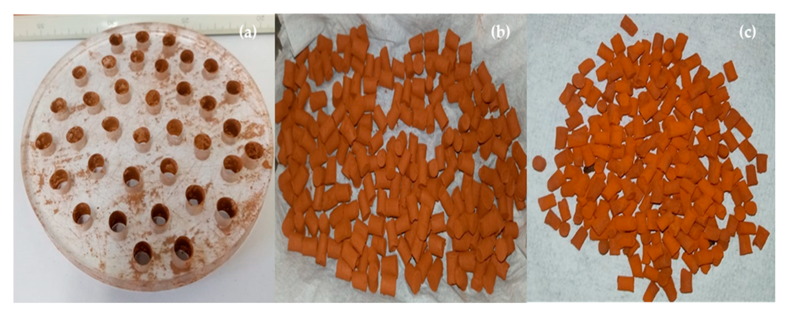
For the production of pellets, an acrylic mold with cylindrical holes of approximately 0.70 cm was constructed used, as shown in Figure 6. The activated red mud pasty cake was placed manually in the mold openings, giving the material the desired shape. After molding, the pellets were submitted to calcination using a muffle (MYLABOR COMERCIO DE PRODUTOS CIENTIFICOS EIRELI, São Paulo-Brazil, Model SSFM6L) at 500 °C for a period of 4 h.
The calcination process aims to improve the textural properties, particularly the catalyst specific area, as well as the pellets thermal stability. The acrylic mold and the pellets before and after calcination is shown in Figure 6a–c.

2.3.4. Experimental Procedures

Pyrolysis

The thermal cracking experiments (without catalyst fixed bed) were performed using 1000 g of waste fat. The fat was fed manually to the reactor by removing it from its place and opening it. The loaded reactor was then recoupled to its cover attached to the system. A graphite seal was inserted between the reactor and its cover to prevent leakage of pyrolysis vapors. The reactor was closed using appropriate mechanical tools and tightly sealed. The reactor R-1 temperature was increased using automatic programming in order to achieve desired heating rate of 10 °C/min and 450 °C final temperature. Mechanical speed of the agitation was 100 rpm. Before experiments were started, some checks were made regarding the cooling water temperature, set to be 10 °C and checking if the mechanical agitation system had its water seal properly turned and functioning. The operational parameters were recorded every 10 min. After initial detection of vapors flowing out of the reactor, four samples were taken according to reaction time. The experiments were finished when no more vapors were flowing out in the gas flaring line. The liquid and solid products were weighted, and the weight of gas determined by difference from the initial feed weight. The organic liquid products (OLP) were submitted to decantation to remove water and filtration. Then, organic liquid products (OLP) physicochemical characterized by density, kinematic viscosity, refractive index, and acid value.

Thermal Catalytic Cracking

The catalytic cracking runs were conducted in similar manner to the thermal cracking experiments, their main difference is in the set-up and operation of the catalyst fixed bed (R-2) present in the catalytic upgrading experiments. After reactor R-1 loading and closing as described in Section Pyrolysis, the red mud pellets were loaded (5.0%, 7.5%, and 10.0% weight related to feed) into reactor R-2. It was then coupled to the system between the reactor R-1 and the condenser, as shown in Figure 2. Reactor R-2 was automatically programmed to achieve slightly higher heating rate than R-1 in order to reach desired temperature before vapors flowed out of reactor R-1. Reactor R-2 initial temperature was chosen to be 20/30 °C higher than initial vapor temperatures in reactor R-1 due to temperature drops occurring when reaction started. Afterwards, both reactors were controlled to achieve same desired final temperature of 450 °C.

2.3.5. Physical-Chemistry Analysis and Chemical Composition of OLP

Physical-Chemistry Analysis of OLP

The organic liquid phase products (OLP) were physicochemical analyzed for acid value, density at 25 °C, kinematic viscosity at 40 °C, and refractive index according to official methods, as described elsewhere [44,45,46,47,48].

Chemical Composition of Organic Liquid Products

The chemical composition of OLPs were determined by CG-MS and the equipment and procedures described in details by Castro et al. [47]. The peak intensity, retention times, and compounds identification were analyzed according to the NIST mass spectra library. The concentrations were expressed in area, as no internal standard was injected to compare the peak areas.

2.3.6. Characterization of Activated Red Mud Pellets

SEM and EDX Analysis

The morphological characterization of chemically activated red mud pellets performed by scanning electron microscopy using a microscope (Tescan GmbH, Brno, Czech Republic, Model: Vega 3). The samples were covered with a thin layer of gold using a Sputter Coater (Leica Biosystems, Germany, Model: Balzers SCD 050). Elemental analysis at a point marked in the surface of red mud pellets was carried out by energy dispersive X-ray spectroscopy (Oxford Instruments, UK, Model: Aztec 4.3) equipped with luminescence and solid-state detector. The EDX analysis was conducted in triplicates and the standard deviation calculated/computed.

XRD Analysis

The crystalline characterization of chemically activated red mud pellets performed by X-ray diffraction using a diffractometer (Rigaku, Japan, Model: MiniFlex600) at the Laboratory of Structural Characterization (FEMAT/UNIFESSPA) and the equipment specifications described as follows: generator (maximum power: 600 W; tube voltage: 40 kV; tube current: 15 mA; X-ray tube: Cu), optics (fixed divergence, scattering and receiving slit; filter; Kβ sheet; monochromator: graphite; soller slit: 5.0°), goniometer (model: vertical, radius: 150 mm, scanning range: −3 A, 145° (2θ); scanning speed: 0.01 to 100°/min (2θ); accuracy: ± 0.02°) and detector (high-speed silicone tape).

2.3.7. Mass Balances by Catalytic Cracking of Vapor Phase Products

Application of mass conservation principle in the form an overall mass balance within the pyrolysis reactor, operating in batch mode, open thermodynamic system, yields the following equations for the material system R-1 (pyrolysis reactor).
m , p y r o l y s i s ˙ m o u t , p y r o l y s i s ˙ = d m F e e d d τ
m , p y r o l y s i u s ˙ = 0
m o u t , p y r o l y s i s ˙ = d m F e e d d τ
m o u t , p y r o l y s i s ˙ = m v a p o r s , p y r o l y s i s ˙
where m ˙ is the mass flow rate entering reactor R-1, m o u t , p y r o l y s i s ˙ is the mass flow rate leaving the reactor R-1, d m F e e d d τ is the time rate variation of feed mass inside reactor R-1, and m v a p o r s , p y r o l y s i s ˙ is the mass flow rate of pyrolysis vapors/volatiles leaving the reactor R-1 and entering the reactor R-2 (catalyst bed reactor). By applying an overall steady state mass balance within the catalyst reactor, operating in continuous mode, open thermodynamic system, yields the following equations for the material system R-2 (catalyst reactor). Assuming that all the vapors leaving reactor R-1, reacts at the solid pellets surface producing gaseous species, the following equations for the material system R-2 (catalyst reactor) applies.
m v a p o r s , p y r o l y s i s ˙ m o u t , c a t a l y s t ˙ = d m v a p o r s d τ
d m v a p o r s d τ = 0
m v a p o r s , p y r o l y s i s ˙ m o u t , c a t a l y s t ˙ = 0
m o u t , c a t a l y s t ˙ = m g a s ˙ + m b i o o i l ˙
where m v a p o r s , p y r o l y s i s , ˙ is the mass flow rate entering reactor R-2, m o u t , c a t a l y s t ˙ is the mass flow rate leaving the reactor R-2, m g a s ˙ is the mass flow rate of non-condensable gases leaving the reactor R-2, computed by difference, and m b o i o i l ˙ is the mass flow rate of bio-oil leaving the condenser. The mass of solid remaining in the reactor R-1 is m s o l i d ˙ . It is possible to obtain the quantity of gas produced on the reaction by a steady state material balance considering weights measured for feed ( m F e e d ˙ ), solids remaining in the reactor ( m s o l i d ) and bio-oil quantity ( m b i o o i l ˙ ) represented by the Equation (9).
m F e e d ˙ = m s o l i d ˙ + m g a s + m b i o o i l ˙
The yields of bio-oil, solid fraction and gas produced in the reaction were calculated and used to evaluate the process as a whole.
Y b i o o i l [ % ] = M B i o o i l M F e e d × 100
Y s o l i d s [ % ] = M S o l i d s M F e e d × 100
Y g a s [ % ] = 100 ( Y b i o o i l + Y s o l i d s )

3. Results

3.1. Characterization of Catalyst

3.1.1. SEM Analysis

The microscopies of red mud pellets activated with 1.0 M HCl after calcination and after upgrading of residual fat pyrolysis vapors at 450 °C, 1.0 atm, 70 min, with 5.0% (wt.) red mud pellets activated with 1.0 M HCl, in batch mode, using a semi-pilot scale reactor of 2.0 L, are illustrated in Figure 7 and Figure 8, respectively. The microscopies of red mud pellets activated with 1.0 M HCl are characterized by the presence of fine round particles with sizes between 0.5 and 2.0 μm as shown in Figure 7c, as well as agglomerates in form of flakes with sizes between 50.0 and 300.0 μm, as described in Figure 7a. The SEM images are according to the results described in the literature [44,49,50,51,52]. As previously described in the literature by Almeida et al. [44], scanning electron microscopies of thermal activated red mud (1000 °C) show the presence of particles of irregular shape with sizes between 3.0 and 4.0 μm, as well as agglomerates of particles in form of flakes with sizes between 10 and 20 μm [44]. Mercury et al. [49] reported the presence of fine particles of round shape and agglomerates of particles with sizes lower than 10 μm in dried red mud. Li et al. [50] reported that activation of red mud with a HCl solution of 0.25 M caused surface erosion, as new cavities appeared after chemical activation with 0.25 M HCl. In addition, CaO, CaCO3, and Fe2O3 acid-soluble oxides/salts were dissolved [50]. This is easy to observe if one compares the composition of oxides identified by XDR in red mud [44], with the punctual elemental analysis of activated red mud pellets described in Table 1. Sahu et al. [51] reported the presence of rounded shape aggregates due to the presence of Na8(Al6Si6O24)Cl2 (sodalite) and CaCO3 (calcite). Both sodalite and calcite are soluble in acid solutions. In addition, microscopies of activated red mud pellets activated with 18 g HCl 31% (wt.), dissolved in 190 g H2O are characterized by the presence of fine round particles with sizes between 0.5 and 2.5 μm [51]. Huang et al. [52] reported the SEM images of raw red mud are smooth and flat, while those treated with 2.0 M HCl show the appearance of cavities and coarsened exterior due to removal of some acid-soluble oxides/salts (CaO, CaCO3, Fe2O3).
SEM images of red mud pellets after upgrading of residual fat pyrolysis vapors at 450 °C, 1.0 atm, 70 min, with 5.0% (wt.) red mud pellets activated with 1.0 M HCl could not accurately display what actually happened on the catalyst surface after the upgrading process. The elemental analysis (Table 2) revealed presence of 26.20% carbon and pellets turned black after the catalytic upgrading process due to carbonization that takes place in the reducing atmosphere of the catalyst surface.

3.1.2. EDX Analysis

Table 2 shows the results of elemental analysis performed by energy dispersive X-ray spectroscopy at a point for raw red mud [53], red mud activated at 1000 °C [44], red mud pellets activated with 1.0 M HCl after calcination at 500 °C and 04 h, and red mud pellets activated with 1.0 M HCl after upgrade of residual fat pyrolysis vapors at 450 °C, 1.0 atmosphere, using a semi-pilot scale reactor of 2.0 L. It might be observed that elemental analysis of raw red mud and red mud thermal activated at 1000 °C are similar as the same chemical elements were identified (C, O, Na, Al, Ca, Ti, Fe, and Si). By thermal activation at 1000 °C the content of sodium and aluminum decreases, while that of Fe increases, being according to results described in the literature [49]. The activation of red mud with a 1.0 HCl solution causes a removal of some acid-soluble oxides/salts (CaO, CaCO3, Fe2O3), decreasing the content of carbon, calcium and iron, and increasing the content of oxygen. In addition, the chemical element chlorine has been detected, as chemical activation was caried out with HCl. As observed earlier, the catalyst after the upgrading process showed presence of carbon due to higher stages of the catalytic cracking reaction happening at the reducing surface of catalyst pores [54,55,56]. Carbon element was not observed in the calcined pellets before the chemical reaction took place.

3.1.3. XRD Analysis

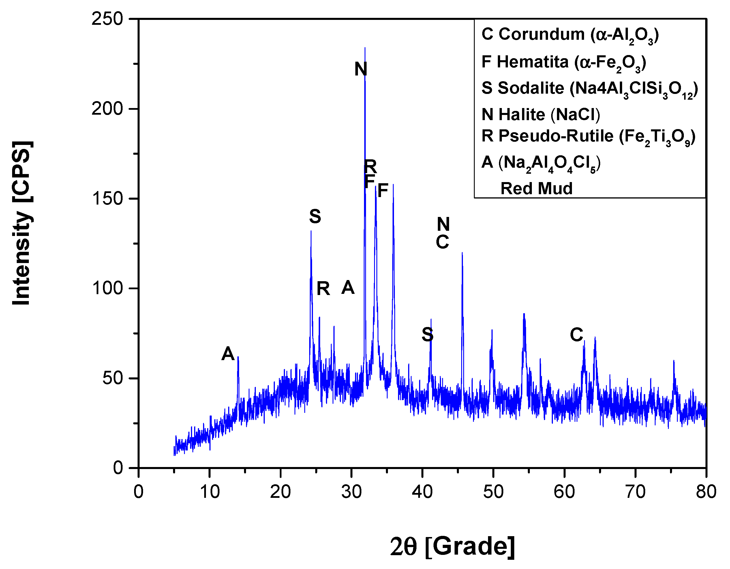
Figure 9 illustrates the diffractogram of red mud pellets activated with 1.0 M HCl after calcination at 400 °C. The XRD shows the presence of two peaks of high intensity, the first observed on the position 2θ: 66.7 (100%), and the on the position 2θ: 45.7 (80%), both associated to the crystalline phase corundum (Al2O3). The peaks of high intensity associated to the crystalline phase Hematite (Fe2O3) were observed on the position 2θ: 33.4 (100%) and on the position 2θ: 35.8 (72.1%), being according to the results reported in the literature by Sahu et al. [51], and Huang et al. [52]. In addition, high intensity peaks were observed on the position 2θ: 24.5 (100%) and medium intensity on the position 2θ: 43.4 (33%), associated to the crystalline phase Sodalite (Na4Al3ClSi3O12). The crystalline phase called pseudo-rutile (Fe2Ti3O9) was observed in two peaks of high intensity on the position 2θ: 25.4 (100%) and on the position 2θ: 33.6 (90%). The peaks of high intensity associated to the crystalline phase (NaAl4O4Cl5) were observed on the position 2θ: 10.1 (100%) and on the position 2θ: 30.8 (80%). In addition, two peaks of high intensity peaks, associated to the crystalline phase Halite (NaCl) were observed on the position 2θ: 31.8 (100%) and on the position 2θ: 45.6 (55%).
The XRD of red mud catalyst is shown in Figure 10. Two peaks are observed, one of high intensity observed on the position 2θ: 24.5 (100%), and another of medium intensity on the position 2θ: 14.0 (40%) associated to the crystalline Sodalite (Na4Al3ClSi3O12). Two peaks associated to sodium oxide (Na2O) were observed, one of high intensity on the position 2θ: 32.7 (100%) and one of low intensity on the position 2θ: 47 (37.9%).
The crystalline phase Nepheline (NaAlSiO4) was observed in two peaks, one of high intensity on the position 2θ: 20.8 (100%) and one of medium intensity on the position 2θ: 34.3 (56.2%). Furthermore, a high intensity peaks was observed on the position 2θ: 35.6 (100%) and a peak of low intensity on the position 2θ: 62.9 (35.9 %), associated to Fe2.18O4Ti0.42. Finally, the peaks associated to the crystalline corundum phase (α-Al2O3) of high and low intensity were observed on the positions 2θ: 25.7 (100%) and 2θ: 43.3 (30.6%).

3.2. Upgrading of Residual Fat Pyrolysis Vapors over a Catalyst Fixed Bed Reactor

3.2.1. Process Conditions, Mass Balances, and Yields of Reaction Products

Table 3 shows the yields of products (bio-oil, solid fraction, water, and gas fraction) obtained along the material balance conducted for increasing catalyst% of 0.0–10.0%.
The experiment without catalyst generated larger quantities of water (11.50%) when compared to the catalyzed ones (2.21–2.80%). This indicates a shift of the mechanism of deoxygenation, thought to occur through two different paths of decarboxylation or decarbonylation. Decarboxylation generates carbon dioxide where decarbonylation produces carbon monoxide and water in the deoxygenation of fatty acids to hydrocarbons, a necessary step for the production of liquid fuels from triglyceride-based material [54,56,57]. The smaller quantity of water produced in the catalyzed experiments indicates that deoxygenation proceeded through decarboxylation generating lesser quantities of toxic monoxide gases. The yields of bio-oil are similar to those for other studies reported in the literature for the catalytic upgrading of lipid-base materials including residual fat [35], castor seed oil [9], using Kaolin, CaO, and ZnO as catalyst, as well as Jatropha waste [15], using HZSM-5, Co/HZSM-5, Ni/HZSM-5, and activated carbon/10.0 M HCl as catalyst. The yields of bio-oil oscillated between 54% to 84%.

3.2.2. Effect of Catalyst-to-Biomass Ratio on the Yields of Bio-Oils

Figure 11 and Figure 12 illustrate the effect of catalyst-to-biomass ratio (C/F) on the yields of bio-oil obtained in this work, compared with similar studies in the literature [8,9,15,25,28,29]. The results depicted in Figure 11 and Figure 12 show that increasing the catalyst-to-biomass ratio causes an increase in the production of bio-oil, since the red mud pellets activated with 1.0 M HCl favored the formation of organic liquid products. On the other hand, the yields of coke, H2O, and gas decrease with increasing catalyst-to-biomass ratio, that is, with increasing bio-oil production. In this context, it is expected that the characteristics of the catalyst, such as types of active centers, strength, and distribution of active sites, as well as the size and structure of pores, selectively increased the yield of bio-oil. Furthermore, the high yield and final distribution of the products are strongly dependent on process variables including reaction temperature, pressure, reactor type, residence time and raw material composition [8,9,15,25,28,29,31]. Thus, the process variables chosen in this work may have optimized the production of bio-oil. In addition, it is observed that the highest yields occur in the beginning of reaction, since, at that moment, the primary cracking occurs, in which occurs the formation of oxygenated compounds (fatty acids, ketones and acrolein) resulting from the rupture of the C-O bond of the glycerides present in vegetable oils and/or animal fat. As the reaction proceeds, larger residence time is achieved, meaning that molecules vaporizing in later stages of processing can achieve secondary cracking where decarboxylating and decarbonylating reactions occur completely producing hydrocarbons [44,45,46,48].
The yield of bio-oil achieved by the catalytic upgrading of pyrolysis vapors of residual fat show that with increasing catalyst content, there is an increase on the production of bio-oil, revealing that the C/F range chosen optimizes the production of liquid fraction. The upgrading of other triglyceride-based material showed similar behavior over a certain C/F range [9]. Benson et al. [54] proposed a mechanism for the catalytic cracking of triglycerides over solid acid catalysts, where the reaction could go through two separate steps. In the first step, the cracking of triglycerides occurs near the glycerol backbone and produces long chain carboxylic acids proceeding to their deoxygenation through decarboxylation and decarbonylation reactions. In the second step, cracking occurs along the chain of hydrocarbons on the triglycerides, producing short chain alkanes and alkenes and smaller chain carboxylic acids. Depending upon the catalyst type and C/F range chosen, one reaction path may be favored over the another; in this case, the use of activated red mud as catalyst over 5–10% in the process favored the first path producing long chain hydrocarbons within the diesel range, increasing the bio-oil yield.
Finding and/or optimizing the catalyst-to-biomass ratio C/F range is critical when producing liquid fuels because it is not only desirable to improve bio-oil yields with increasing catalyst content, but also the quality of bio-oil produced by effective deoxygenation and conversion into hydrocarbons. However, this is not always possible due to simultaneous occurrence of deoxygenation reactions and cracking/fragmentation reactions producing small gaseous hydrocarbons molecules such as CH4 and C2H6 that takes place during the catalytic upgrading. High residence times, that is, high catalyst-to-biomass ratios (C/F) may lead to excessive gas formation/production in the form of small chain hydrocarbons decreasing the yields of bio-oil and, consequently, reducing the production of liquid biofuels. Moreover, high catalyst-to-biomass ratios (C/F) leads to higher investment and operational costs as more catalyst is needed and longer fixed-bed reactors are required. It is important to understand that the effect of catalyst-to-biomass ratio (C/F) on yield and quality of bio-oil is associated to chemical and process conditions, transport and physical properties of the solid catalyst, such as surface area, pore sizes, void fractions and mass flow rates of vapors through the fixed catalyst bed. In this context, estimating the effect of catalyst-to-biomass ratio (C/F) may help on the optimum process design to achieve desired product yields and composition.
By comparing the results illustrated in Figure 11 and Figure 12, it has been observed that catalyst content limits the increase in bio-oil yield, so that after this limit, the yield of bio-oil decays, as shown in the literature by Koul et al. [9] and Balasundram et al. [25]. Koul et al. [9] obtained the highest bio-oil yield with catalyst-to-biomass of 0.15 using Kaolin as catalyst and castor seed oil, while Balasundram et al. [25] obtained the highest bio-oil yield with catalyst-to-biomass of 1.0 using HZSM-5 as catalyst and sugarcane bagasse. However, Balasundram et al. [25] reported an increase of bio-oil yield with increasing catalyst-to-biomass ratio in the range 0.5–2.0 using Ce/HZSM-5 as catalyst and sugarcane bagasse.

3.2.3. Effect of Reaction Time on the Yields of Bio-Oil and H2O

The results illustrated in Table 4, Table 5, Table 6 and Table 7 show that at the beginning of reaction, residual water is collected, proving that residual fat still contains water, that is, pre-processing (heating, homogenization) and separation processes (dehydration, sieving) could not completely remove residual water. In addition, the highest partial yield of bio-oil is obtained at the second withdraw between 50 and 60 min. The experiments described in Table 4, Table 5, Table 6 and Table 7 makes it possible not only to investigate the behavior of process kinetics, but also to study the effect of reaction time on the physicochemical properties (density, kinematic viscosity, and acidity) and chemical composition of bio-oil.

3.2.4. Effect of Reaction Time on the Physicochemical Properties of Bio-Oil

Table 8 illustrates the effect of reaction time on the physicochemical properties (density, kinematic viscosity, and acidity) of bio-oil. It might be observed that density, viscosity, and acid value decrease with increasing reaction time, showing that, as reaction progresses, the product composition change from heavy oil-like compounds to shorter chain hydrocarbons. In addition, the reduction of acid value indicates that reaction products are becoming less oxygenated. Proposed mechanisms show that the first step of triglyceride cracking is carboxylic acids formation and deoxygenation proceeds as a secondary step to produce less oxygenated compounds (aldehydes and ketones) and hydrocarbons [35,36,37,39,40,41,42,43,44,45,46,47]. As the experiments were conducted on semi-batch mode, the feed composition is altered as thermal cracking occurs at reactor R-01 and pyrolytic vapors are formed flowing out of the reactor to the catalyst fixed bed. Then, the residence time of feed material in later stages of reaction is higher and secondary cracking reactions as decarboxylation and decarbonylation can occur producing shorter chain hydrocarbons and low acid value.
The variation of bio-oil physicochemical properties with reaction time gives insights into the transient aspect of cracking reactions carried out in semi-batch mode. One should be able to use the information contained in the following tables and graphs to adjust process design and conditions in order to be able to achieve desired characteristics of bio-oil as well as in the decision making when operating such equipment. Moreover, the evaluation of process parameters with time may help to set feed flow rates when operating in continuous mode.

Effect of Reaction Time on the Density of Bio-Oil

The variation of density during course of reaction is recorded in Figure 13. The range of densities obtained is similar to others in literature [44,45,46] ranging from 0.81–0.87 g/cm3. Almeida et al. [44] obtained bio-oil with 0.87 g/cm3 with the catalytic cracking of waste fat utilizing activated red mud as catalyst in liquid-phase. The slightly lower densities obtained for the catalytically upgraded bio-oils of this work indicate that the inclusion of the thermally heated fixed bed reactor contributed to further crack molecules coming from reactor R-1 producing smaller compounds with higher volatility and lower densities. It is important to note that increasing catalyst content favored higher densities. The red mud catalyst could be promoting a reaction path where liquid product is composed of larger molecules through condensation and polymerization reactions [54,56]. These might be associated with the fact that the catalytically upgraded experiments generated lesser amounts of water in the reaction, proceeding through decarboxylation instead of decarbonylation. The expected decrease of density with reaction time could be correlated with a first order exponential decay model with R2 between 0.965 and 0.988 for almost all experiments except for the ones using 5.0% red mud pellets, correlated with a linear equation.

Effect of Reaction Time on the Viscosity of Bio-Oil

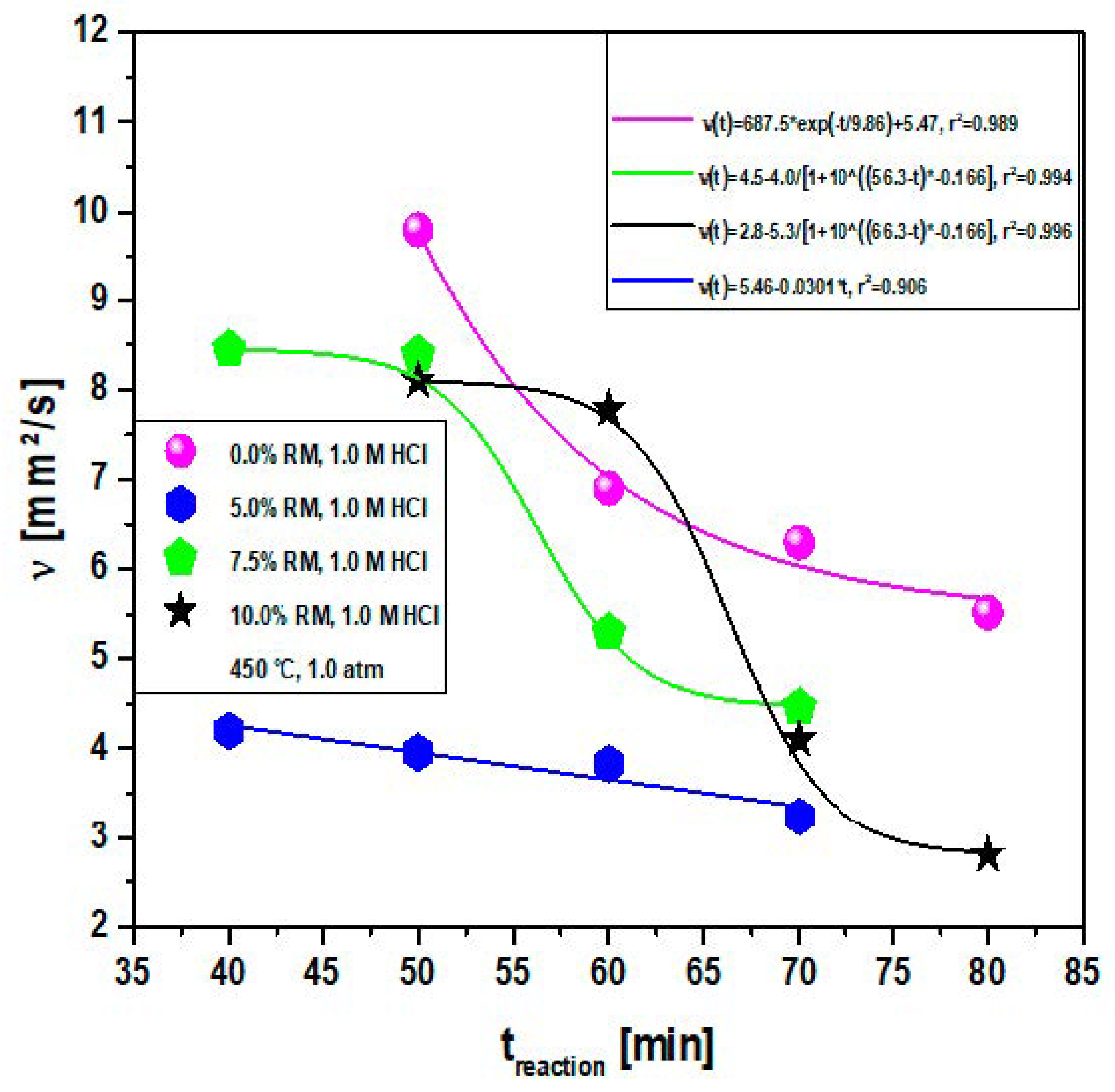
Figure 14 shows the behavior of bio-oil viscosity during the course of reaction. As expected, the viscosity decreases with increasing reaction time approaching minimum values on the range of 2.8–4.5 mm2/s for the experiments conducted using catalyzed fixed bed and 5.5 mm2/s for the thermal experiment. The values of viscosity reported by Almeida et al. ranged from 10.96–14.08 mm2/s but the analysis was conducted at 20 °C [44]. One should observe that for all the experiments, viscosity is initially higher when fatty acids are formed during the first step of cracking reaction and it decreases until reaching a minimum value where the reaction approaches steady state. Smaller sizes molecules are also formed as the reaction proceeds, reducing bio-oil viscosity. Long chain aldehydes, fatty acids, and ketones present higher viscosity than hydrocarbons of the same lengths and initial reaction stages show higher concentration of these compounds [58,59]. For the most part, kinematic viscosity of bio-oils could be correlated with a first order exponential model except for the 5.0% experiment correlated with a linear equation. They are properly showed in Figure 14.

Effect of Reaction Time on the Acidity of Bio-Oil

The acid value is an important measurement for the analysis of bio-oils obtained through catalytic cracking of triglyceride-based materials. As carboxylic fatty acids are formed, vaporized, and condensed into liquid bio-oil during the thermal cracking of oils and fats, acidity is high if complete conversion is not achieved. If deoxygenation of fatty acids occurs producing hydrocarbons, there is a decrease of acid value reaching neutrality when complete conversion is obtained. As acid value is determined through a titrating procedure, it can be used as a rapid and inexpensive tool to analyze hydrocarbon composition of bio-oil. Even though it is not foolproof, the acid value can at least suggest the fatty acid concentration present in the bio-oil.
The range of acid values displayed by all experiments is in accord to results obtained from other similar works published in the literature [44,45,46,60,61]. Almeida et al. [44] obtained acid values ranging from 84.65 to 109.55 mg KOH/g for the bio-oil obtained through liquid phase (one-stage) catalytic cracking of waste fat using 5-15% calcined red mud catalyst at 450 °C on a 1.0 atm pilot plant. It is important to realize that acid values reported here are not the bulk acidity of bio-oil (as reported by Almeida et al), but the variation of it in respect to reaction time, since liquid bio-oil was cut into fractions, it is necessary to do some calculations considering the weight and acid value of each fraction of bio-oil obtained in order to obtain the bulk acid value of bio-oil obtained through the upgrading process. Table 9 compiles the necessary information and display calculated bulk acid values.
It is possible to observe that bulk acid values obtained through the upgrading process are comparable to those obtained by Almeida et al. [44] with somewhat lower values for the catalytically upgraded bio-oils of this work. The experiment using catalyst fixed bed loaded with 5.0% of red mud produced bio-oil with bulk acid value lower than for the thermal experiment with no catalyst bed, hinting to the effectiveness of a thermally heated stage of vapor cracking to upgrade bio-oil composition and properties. Romero et al. [60] conducted experiments on the pyrolysis of waste animal fat using red mud catalyst in liquid phase with fractionation of bio-oil obtained in respect with reaction time in the same pilot plant used by Almeida et al. [44]. Bio-oil initially collected showed 149.25 mg KOH/g of acid value and final cut displayed acidity of 19.34 mg KOH/g, similar results when compared to this work. It was possible to obtain final acid values lower than 10 mg KOH/g of bio-oil for experiments conducted with 5.0 and 7.5% of red mud catalyst, better results for acidity than obtained by Romero et al.; the pyrolysis vapors contact with the heterogeneous solid phase of catalyst should be better for the fixed bed than in liquid phase where only limited contact should be expected as vapors formed flow out quickly from the reactor. It should be noted that equipment used by Romero et al. and Almeida et al. is similar in mode of operation (semi-continuous) and construction to the one used on this work, except on a larger scale. It is known that equipment and process conditions greatly affect products yield and composition of bio-oil obtained from pyrolysis of triglycerides, specially heat transfer rates [39]. Therefore, one should only carefully compare experiments conducted with different equipment.
Figure 15 shows the influence of reaction time on the density of bio-oil. For all the experiments, the acidity of bio-oil, expressed by the acid value, decreases drastically as the reaction time progresses. The experiments without catalyst and with 5.0% (wt.) red mud pellets activated with 1.0 M HCl were correlated with a first order exponential decay model, exhibiting root-mean-square error (r2) of 0.999 and 0.998, respectively, while the experiments with 7.5 and 10.0% (wt.) red mud pellets activated with 1.0 M HCl were correlated with a DoseResp function, exhibiting root-mean-square errors (r2) of 0.992 and 0.966, respectively. By DoseResp function, A1 and A2 are the bottom (initial value) and top (final value) asymptotes, respectively, being A1 equal to 8.8 and A2 equal to 135.2 for the experiment with 7.5% (wt.) red mud pellets activated with 1.0 M HCl, and A1 equal to 26.5 and A2 equal to 124.4 for the experiment with 10.0% (wt.) red mud pellets activated with 1.0 M HCl. In addition, except for the experiment without catalyst, holding the reaction time constant (treaction = 60 min), the acid value decreases as the content of catalyst diminishes, showing that the catalyst fixed bed filled with 5.0% (wt.) red mud pellets activated with 1.0 M HCl proves to be can optimum value.
As observed in Figure 15, as soon as the first sample is withdrawn, the acid value is high, ranging between 135.3 and 113.9 mg KOH/g, due to formation of carboxylic acids, associated to the primary cracking. Afterwards, in the middle to the end of the reaction, deoxygenation of triglycerides and fatty acids molecules occurs by means of de-carboxylation/de-carbonylation, producing mixtures rich in hydrocarbons and poor of oxygenates, particularly carboxylic acids [44,45,46,48].

3.2.5. Effect of Reaction Time on the Content of Hydrocarbons and Oxygenates in Bio-Oil

Hydrocarbon content, together with acid value and other physicochemical properties, is one of the most important aspects of fuel production from triglyceride-based materials. It is desirable to achieve high hydrocarbon content in order to obtain bio-oil similar to petroleum and low content of oxygenated compounds (similar to initial feed of triglycerides and fatty acids), those showing undesirable properties like high viscosity, acidity and coke deposition on motor lines and chamber [62]. Chemical composition analysis through GC-MS can also provide interesting information not clearly shown by physicochemical analysis as the distribution of products based on chain length, aromatic compounds quantity and presence of some oxygenated compounds (aldehydes, ketones). This information can be used to evaluate the effect and effectiveness of the catalyst fixed bed in a variety of ways.
For example, the liquid fraction distribution of compounds based on chain length can be utilized to analyze the cracking promoted by the packed fixed bed with catalyst. Table 10 compares the distribution of products based on carbon chain length for the thermal cracking and the experiment conducted using 5.0% red mud in the catalyst fixed bed, for the same reaction time (20 min after initial vapor formation). It is important to remember that the thermal cracking experiments were conducted without presence of catalyst fixed bed meaning that no vapor-phase cracking was realized. The results show that using the heated fixed bed to upgrade pyrolysis vapors were effective to generate shorter chain length molecules as there was a substantial increase in those compounds. This is corroborated by gas yields obtained, 34.22% for 5.0% red mud against 2.48% for the thermal cracking, proving that smaller chain molecules were formed. Additional calculations show that there was a 43.75% decrease in C16+ compounds and a 73.1% increase in lower chain length compounds.
For additional information and comparation, Table 11 shows the chemical functions and its composition, expressed in %.area, of all the chromatograms of bio-oils compared in Table 10, for an intermediary moment in the reaction, corresponding to 20 min from the start of vaporization. It can be seen that the presence of catalyst fixed bed improved hydrocarbon composition of bio-oil by 72.36%. Furthermore, oxygenated compounds were present in smaller amounts than for the thermal experiment, showing presence of ketones and small amounts of aldehydes and alcohols. It is interesting to note that no carboxylic acids were present after 20 min of reaction, indicating that initial phase of cracking reaction (where there is formation and vaporization of fatty acids) had finished. For the same reaction time, the thermal cracking bio-oil composition revealed presence of carboxylic acids and lower content of hydrocarbons, meaning that deoxygenation was not complete. The presence of heated catalyst fixed bed could achieve almost full deoxygenation by that reaction time, indicating that higher deoxygenation rate was obtained.
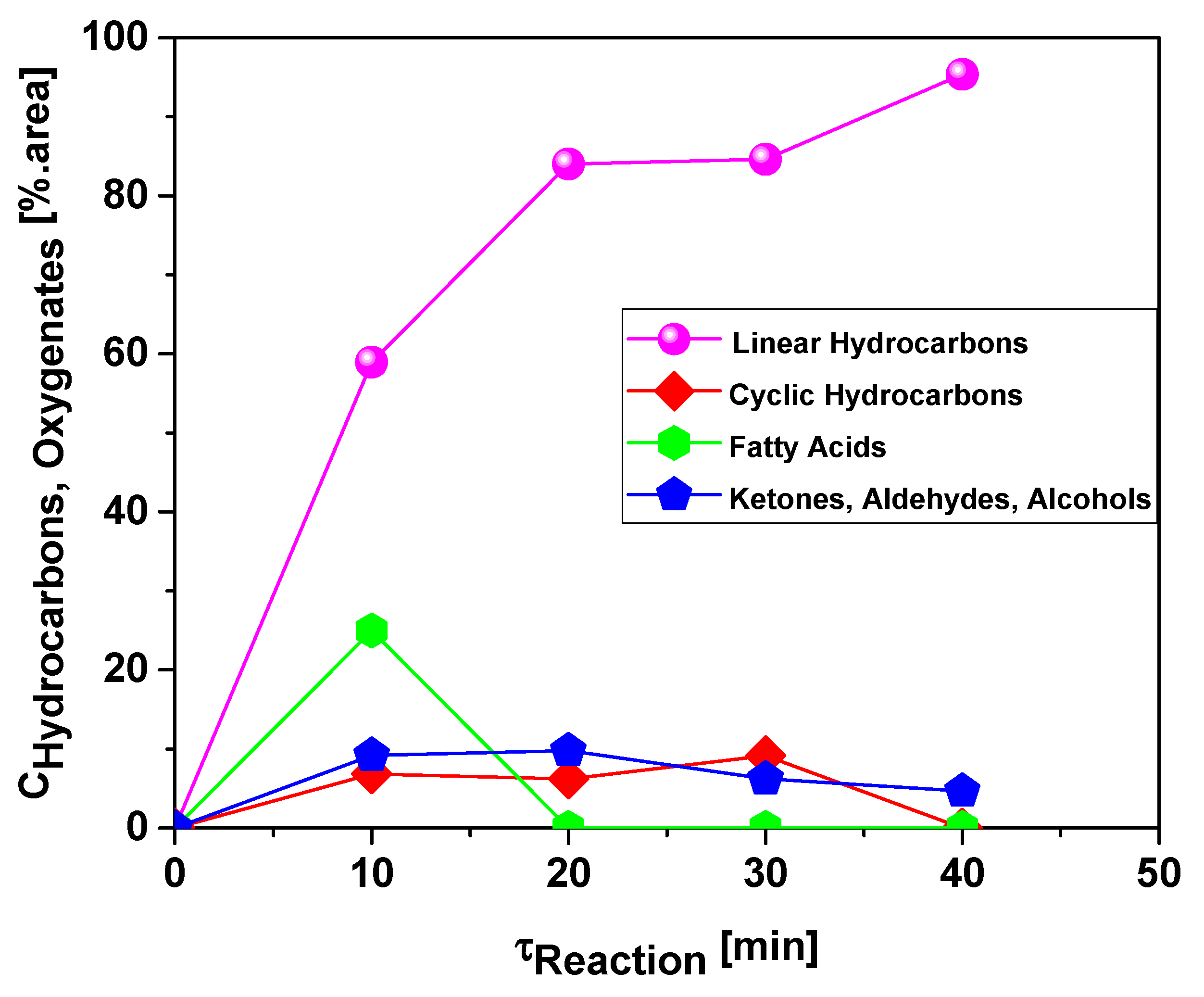
Figure 16 and Figure 17 illustrate the variation of chemical composition (chemical functions) of bio-oils obtained through thermal cracking (Figure 16) and catalytic upgrading (5.0%) (Figure 17) with reaction time. It can be observed that higher concentration of hydrocarbons was achieved for the catalytically upgraded bio-oil and fatty acids concentration achieved maximum value before being reduced to 0.0% with 20 min of reaction. For the thermal experiment, carboxylic acids were still present even after 40 min of reaction, showing that deoxygenation proceeded further for upgraded bio-oil. The thermal experiment shows that initially there is formation of fatty acids from triglycerides present and those compounds are further deoxygenated to other oxygenated compounds like ketones and aldehydes. Those proceed further, becoming hydrocarbons through decarboxylation and decarbonylation reactions. Indeed, the experiments show that fatty acid composition decrease and ketone formation increase until a maximum value before decreasing. The upgraded bio-oil could decrease even the ketone composition to values below 5.0% area of chromatogram.
Figure 18 and Figure 19 illustrate the effect of reaction time on the content of hydrocarbons and oxygenates, respectively. The chemical functions, sum of peak areas, CAS numbers, and retention times of all the molecules identified in bio-oil by GC-MS by the upgrading of residual fat pyrolysis vapors at 450 °C, 1.0 atmosphere, 0.0%, 5.0%, 7.5%, and 10.0% (wt.) red mud pellets activated with 1.0 M HCl, during the course of reaction at 40, 50, 60, 70, and 80 min, using a catalyst fixed bed reactor, using a semi-pilot scale two-stage reactor of 2.0 L, are illustrated in Supplementary Tables S1–S16.
For all the experiments, the concentration of hydrocarbons in bio-oil increases sharply with reaction time. The experiments without catalyst and with 10.0% (wt.) red mud pellets activated with 1.0 M HCl were correlated were correlated with a DoseResp function, exhibiting root-mean-square errors (r2) of 0.99 and 0.98, respectively, while the experiments with 5.0 and 7.5% (wt.) red mud pellets activated with 1.0 M HCl were correlated with a first order exponential growth model, exhibiting root-mean-square error (r2) of 0.99 and 0.99, respectively. The concentration of hydrocarbons in bio-oil increases due to the catalytic deoxygenation of fatty acids molecules, by means of de-carboxylation/de-carbonylation, producing aliphatic and aromatic hydrocarbons, as reported in the literature [44,45,46,48]. On the contrary, for all the experiments, the concentration of oxygenates in bio-oil decreases sharply as the reaction time increases The experiments without catalyst and with 10.0% (wt.) red mud pellets activated with 1.0 M HCl were correlated with a DoseResp function, exhibiting root-mean-square errors (r2) of 0.99 and 0.98, respectively, while the experiments with 5.0 and 7.5% (wt.) red mud pellets activated with 1.0 M HCl were correlated with a first order exponential growth model, exhibiting root-mean-square error (r2) of 0.99 and 0.99, respectively.

4. Conclusions

The red mud pellets activated with 1.0 M HCl proved to be very efficient for the deoxygenation of triglycerides and fatty acids molecules by means of de-carboxylation/de-carbonylation, producing mixtures rich in hydrocarbons and poor of oxygenates.
The catalytic upgrading experiments of residual fat pyrolysis vapors at 450 °C, 1.0 atm, 5.0% (wt.) red mud pellets activated with 1.0 M HCl, using a catalyst fixed bed reactor, using a semi-pilot scale two-stage reactor of 2.0 L, could achieve hydrocarbon concentrations up to 95.35% (area).
The yield of bio-oil, physicochemical properties, and chemical composition changes were evaluated as a function of reaction time and their behavior correlated with mathematical equations. As the reaction progresses, there is reduction of density, viscosity, and acid value of bio-oil as the composition changes from oxygenated compounds (carboxylic acids, ketones, and aldehydes) to hydrocarbons in the diesel range.
The chosen catalyst-to-biomass ratio (C/F) range revealed that yield of bio-oil increases with catalyst content and that activated red mud pellets favored a reaction pathway producing carboxylic acids and subsequent deoxygenation over the reaction producing short chain hydrocarbons and smaller chain carboxylic acids as described in literature [54]. Red mud, with its alumina and hematite composition reveals itself to be a mixed catalyst adequate for the production of hydrocarbons.
One can observe that correct choosing of process conditions may affect the yield and quality of the bio-oil produced from residual fat.
It is expected that chemical (feed and catalyst type) and physical (superficial area, pore size, residence time, temperature, pressure, vapor flow rate) conditions may affect the process of upgrading of pyrolysis vapors and reveals the robustness of the technology, as the design can adapt to different types of feed and desired product composition.
The catalytic upgrading of vapors from pyrolysis of triglyceride materials is a promising technique for production of liquid biofuels when compared to other materials like biomass or coal. Yields of liquid fraction are higher and the chosen catalyst-to-biomass ratio (C/F) range shows that low amounts of catalyst can be used to effectively produce hydrocarbons and increase bio-oil yield. The composition of upgraded bio-oil is closer to transport fuels and its purification should be easier and cheaper than biomass or coal pyrolysis. However, full conversion of triglycerides materials was not achieved because reaction was carried in semi-batch mode and initially high amounts of carboxylic acids were collected. Proper recirculation of feed can probably be a way to achieve higher conversion values. Pyrolysis methods have shown to be an effective way to deal with high FFA materials and the recirculation or reflux of incomplete reactions products should not be a problem for the processing technique.

Supplementary Materials

The following supporting information can be downloaded at: https://www.mdpi.com/article/10.3390/en15155595/s1, Table S1: Classes of compounds, summation of peak areas, CAS number, and retention times of chemical compounds identified by CG-MS in bio-oil by pyrolysis of residual fat at 450 °C, 1.0 atm, 50 min, using a pyrolysis reactor of 2.0 L, in semi pilot scale. Table S2: Classes of compounds, summation of peak areas, CAS number, and retention times of chemical compounds identified by CG-MS in bio-oil by pyrolysis of residual fat at 450 °C, 1.0 atm, 60 min, using a pyrolysis reactor of 2.0 L, in semi pilot scale. Table S3: Classes of compounds, summation of peak areas, CAS number, and retention times of chemical compounds identified by CG-MS in bio-oil by pyrolysis of residual fat at 450 °C, 1.0 atm, 70 min, using a pyrolysis reactor of 2.0 L, in semi pilot scale. Table S4: Classes of compounds, summation of peak areas, CAS number, and retention times of chemical compounds identified by CG-MS in bio-oil by pyrolysis of residual fat at 450 °C, 1.0 atm, 80 min, using a pyrolysis reactor of 2.0 L, in semi pilot scale. Table S5: Classes of compounds, summation of peak areas, CAS number, and retention times of chemical compounds identified by CG-MS in bio-oil by catalytic upgrading of residual fat pyrolysis vapors at 450 °C, 1.0 atm, 5.0% (wt.) Red Mud pellets activated with 1.0 M HCl, 40 min, using a catalyst fixed bed reactor, in semi pilot scale two-stage reactor of 2.0 L. Table S6: Classes of compounds, summation of peak areas, CAS number, and retention times of chemical compounds identified by CG-MS in bio-oil by catalytic upgrading of residual fat pyrolysis vapors at 450 °C, 1.0 atm, 5.0% (wt.) Red Mud pellets activated with 1.0 M HCl, 50 min, using a catalyst fixed bed reactor, in semi pilot scale two-stage reactor of 2.0 L. Table S7: Classes of compounds, summation of peak areas, CAS number, and retention times of chemical compounds identified by CG-MS in bio-oil by catalytic upgrading of residual fat pyrolysis vapors at 450 °C, 1.0 atm, 5.0% (wt.) Red Mud pellets activated with 1.0 M HCl, 60 min, using a catalyst fixed bed reactor, in semi pilot scale two-stage reactor of 2.0 L. Table S8: Classes of compounds, summation of peak areas, CAS number, and retention times of chemical compounds identified by CG-MS in bio-oil by catalytic upgrading of residual fat pyrolysis vapors at 450 °C, 1.0 atm, 5.0% (wt.) Red Mud pellets activated with 1.0 M HCl, 70 min, using a catalyst fixed bed reactor, in semi pilot scale two-stage reactor of 2.0 L. Table S9: Classes of compounds, summation of peak areas, CAS number, and retention times of chemical compounds identified by CG-MS in bio-oil by catalytic upgrading of residual fat pyrolysis vapors at 450 °C, 1.0 atm, 7.5% (wt.) Red Mud pellets activated with 1.0 M HCl, 40 min, using a catalyst fixed bed reactor, in semi pilot scale two-stage reactor of 2.0 L. Table S10: Classes of compounds, summation of peak areas, CAS number, and retention times of chemical compounds identified by CG-MS in bio-oil by catalytic upgrading of residual fat pyrolysis vapors at 450 °C, 1.0 atm, 7.5% (wt.) Red Mud pellets activated with 1.0 M HCl, 50 min, using a catalyst fixed bed reactor, in semi pilot scale two-stage reactor of 2.0 L. Table S11: Classes of compounds, summation of peak areas, CAS number, and retention times of chemical compounds identified by CG-MS in bio-oil by catalytic upgrading of residual fat pyrolysis vapors at 450 °C, 1.0 atm, 7.5% (wt.) Red Mud pellets activated with 1.0 M HCl, 60 min, using a catalyst fixed bed reactor, in semi pilot scale two-stage reactor of 2.0 L. Table S12: Classes of compounds, summation of peak areas, CAS number, and retention times of chemical compounds identified by CG-MS in bio-oil by catalytic upgrading of residual fat pyrolysis vapors at 450 °C, 1.0 atm, 7.5% (wt.) Red Mud pellets activated with 1.0 M HCl, 70 min, using a catalyst fixed bed reactor, in semi pilot scale two-stage reactor of 2.0 L. Table S13: Classes of compounds, summation of peak areas, CAS number, and retention times of chemical compounds identified by CG-MS in bio-oil by catalytic upgrading of residual fat pyrolysis vapors at 450 °C, 1.0 atm, 10.0% (wt.) Red Mud pellets activated with 1.0 M HCl, 50 min, using a catalyst fixed bed reactor, in semi pilot scale two-stage reactor of 2.0 L. Table S14: Classes of compounds, summation of peak areas, CAS number, and retention times of chemical compounds identified by CG-MS in bio-oil by catalytic upgrading of residual fat pyrolysis vapors at 450 °C, 1.0 atm, 10.0% (wt.) Red Mud pellets activated with 1.0 M HCl, 60 min, using a catalyst fixed bed reactor, in semi pilot scale two-stage reactor of 2.0 L. Table S15: Classes of compounds, summation of peak areas, CAS number, and retention times of chemical compounds identified by CG-MS in bio-oil by catalytic upgrading of residual fat pyrolysis vapors at 450 °C, 1.0 atm, 10.0% (wt.) Red Mud pellets activated with 1.0 M HCl, 70 min, using a catalyst fixed bed reactor, in semi pilot scale two-stage reactor of 2.0 L. Table S16: Classes of compounds, summation of peak areas, CAS number, and retention times of chemical compounds identified by CG-MS in in bio-oil by catalytic upgrading of residual fat pyrolysis vapors at 450 °C, 1.0 atm, 10.0% (wt.) Red Mud pellets activated with 1.0 M HCl, 80 min, using a catalyst fixed bed reactor, in semi pilot scale two-stage reactor of 2.0 L.

Author Contributions

C.C.F. contributed with formal analysis and writing original draft preparation, investigation, and methodology; L.P.B. contributed with formal analysis and writing original draft preparation, investigation, and methodology; A.F.d.F.C. contributed with formal analysis and writing original draft preparation; H.J.d.S.R. contributed with investigation and methodology; N.L.M. contributed with chemical analysis; Y.S.C. contributed with chemical analysis; A.C.F.B. contributed with chemical analysis; S.A.P.d.M. contributed with chemical analysis and formal analysis, F.P.d.C.A. contributed with chemical analysis and formal analysis C.C.V.Q. contributed with chemical analysis; D.A.R.d.C. contributed with investigation and methodology; M.C.S. contributed with formal analysis, investigation, and methodology; N.M.M. contributed with formal analysis, investigation, and methodology; S.D.J. contributed with resources and chemical analysis; L.E.P.B. with co-supervision and resources; and N.T.M. contributed with supervision, conceptualization, and data curation. All authors have read and agreed to the published version of the manuscript.

Funding

This research received no external funding.

Institutional Review Board Statement

Not applicable.

Informed Consent Statement

Not applicable.

Acknowledgments

I would like to acknowledge and dedicate this research in memory to Hélio da Silva Almeida; he used to work at the Faculty of Sanitary and Environmental Engineering/UFPa, and passed away on 13 March 2021. His contagious joy, dedication, intelligence, honesty, seriousness, and kindness will always be remembered in our hearts.

Conflicts of Interest

The authors declare no conflict of interest.

References

  1. Lu, Q.; Zhang, Y.; Tang, Z.; Li, W.Z.; Zhu, X.F. Catalytic Upgrading of Biomass Fast Pyrolysis Vapors with Titania and Zirconia/Titania Based Catalysts. Fuel 2010, 89, 2096–2103. [Google Scholar] [CrossRef]
  2. Li, G.; Yan, L.; Zhao, R.; Li, F. Improving Aromatic Hydrocarbons Yield from Coal Pyrolysis Volatile Products over HZSM-5 and Mo-Modified HZSM-5. Fuel 2014, 130, 154–159. [Google Scholar] [CrossRef]
  3. Ren, X.-Y.; Cao, J.-P.; Zhao, X.-Y.; Yang, Z.; Liu, T.-L.; Fan, X.; Zhao, Y.-P.; Wei, X.-Y. Catalytic Upgrading of Pyrolysis Vapors from Lignite over Mono/Bimetal-Loaded Mesoporous HZSM-5. Fuel 2018, 218, 33–40. [Google Scholar] [CrossRef]
  4. Liu, T.L.; Cao, J.P.; Zhao, X.Y.; Wang, J.X.; Ren, X.Y.; Fan, X.; Zhao, Y.P.; Wei, X.Y. In Situ Upgrading of Shengli Lignite Pyrolysis Vapors over Metal-Loaded HZSM-5 Catalyst. Fuel Process. Technol. 2017, 160, 19–26. [Google Scholar] [CrossRef]
  5. Yan, L.J.; Kong, X.J.; Zhao, R.F.; Li, F.; Xie, K.C. Catalytic Upgrading of Gaseous Tars over Zeolite Catalysts during Coal Pyrolysis. Fuel Process. Technol. 2015, 138, 424–429. [Google Scholar] [CrossRef]
  6. Yang, Z.; Cao, J.P.; Ren, X.Y.; Zhao, X.Y.; Liu, S.N.; Guo, Z.X.; Shen, W.Z.; Bai, J.; Wei, X.Y. Preparation of Hierarchical HZSM-5 Based Sulfated Zirconium Solid Acid Catalyst for Catalytic Upgrading of Pyrolysis Vapors from Lignite Pyrolysis. Fuel 2019, 237, 1079–1085. [Google Scholar] [CrossRef]
  7. Yaman, E.; Yargic, A.S.; Ozbay, N.; Uzun, B.B.; Kalogiannis, K.G.; Stefanidis, S.D.; Pachatouridou, E.P.; Iliopoulou, E.F.; Lappas, A.A. Catalytic Upgrading of Pyrolysis Vapours: Effect of Catalyst Support and Metal Type on Phenolic Content of Bio-Oil. J. Clean. Prod. 2018, 185, 52–61. [Google Scholar] [CrossRef]
  8. Fan, Y.; Cai, Y.; Li, X.; Yu, N.; Yin, H. Catalytic Upgrading of Pyrolytic Vapors from the Vacuum Pyrolysis of Rape Straw over Nanocrystalline HZSM-5 Zeolite in a Two-Stage Fixed-Bed Reactor. J. Anal. Appl. Pyrolysis 2014, 108, 185–195. [Google Scholar] [CrossRef]
  9. Koul, M.; Shadangi, K.P.; Mohanty, K. Effect of Catalytic Vapour Cracking on Fuel Properties and Composition of Castor Seed Pyrolytic Oil. J. Anal. Appl. Pyrolysis 2016, 120, 103–109. [Google Scholar] [CrossRef]
  10. Zheng, Y.; Wang, F.; Yang, X.; Huang, Y.; Liu, C.; Zheng, Z.; Gu, J. Study on Aromatics Production via the Catalytic Pyrolysis Vapor Upgrading of Biomass Using Metal-Loaded Modified H-ZSM-5. J. Anal. Appl. Pyrolysis 2017, 126, 169–179. [Google Scholar] [CrossRef]
  11. Ren, X.Y.; Cao, J.P.; Zhao, X.Y.; Shen, W.Z.; Wei, X.Y. Increasing Light Aromatic Products during Upgrading of Lignite Pyrolysis Vapor over Co-Modified HZSM-5. J. Anal. Appl. Pyrolysis 2018, 130, 190–197. [Google Scholar] [CrossRef]
  12. Cai, Y.; Fan, Y.; Li, X.; Chen, L.; Wang, J. Preparation of Refined Bio-Oil by Catalytic Transformation of Vapors Derived from Vacuum Pyrolysis of Rape Straw over Modified HZSM-5. Energy 2016, 102, 95–105. [Google Scholar] [CrossRef]
  13. Zhang, S.; Zhang, H.; Liu, X.; Zhu, S.; Hu, L.; Zhang, Q. Upgrading of Bio-Oil from Catalytic Pyrolysis of Pretreated Rice Husk over Fe-Modified ZSM-5 Zeolite Catalyst. Fuel Process. Technol. 2018, 175, 17–25. [Google Scholar] [CrossRef]
  14. Iliopoulou, E.F.; Stefanidis, S.D.; Kalogiannis, K.G.; Delimitis, A.; Lappas, A.A.; Triantafyllidis, K.S. Catalytic Upgrading of Biomass Pyrolysis Vapors Using Transition Metal-Modified ZSM-5 Zeolite. Appl. Catal. B Environ. 2012, 127, 281–290. [Google Scholar] [CrossRef]
  15. Vichaphund, S.; Aht-ong, D.; Sricharoenchaikul, V.; Atong, D. Catalytic Upgrading Pyrolysis Vapors of Jatropha Waste Using Metal Promoted ZSM-5 Catalysts: An Analytical PY-GC/MS. Renew. Energy 2014, 65, 70–77. [Google Scholar] [CrossRef] [Green Version]
  16. Li, X.; Zhang, X.; Shao, S.; Dong, L.; Zhang, J.; Hu, C.; Cai, Y. Catalytic Upgrading of Pyrolysis Vapor from Rape Straw in a Vacuum Pyrolysis System over La/HZSM-5 with Hierarchical Structure. Bioresour. Technol. 2018, 259, 191–197. [Google Scholar] [CrossRef] [PubMed]
  17. Nguyen, T.S.; Zabeti, M.; Lefferts, L.; Brem, G.; Seshan, K. Catalytic Upgrading of Biomass Pyrolysis Vapours Using Faujasite Zeolite Catalysts. Biomass Bioenergy 2013, 48, 100–110. [Google Scholar] [CrossRef]
  18. Triantafyllidis, K.S.; Iliopoulou, E.F.; Antonakou, E.V.; Lappas, A.A.; Wang, H.; Pinnavaia, T.J. Hydrothermally Stable Mesoporous Aluminosilicates (MSU-S) Assembled from Zeolite Seeds as Catalysts for Biomass Pyrolysis. Microporous Mesoporous Mater. 2007, 99, 132–139. [Google Scholar] [CrossRef]
  19. Li, X.; Dong, L.; Zhang, J.; Hu, C.; Zhang, X.; Cai, Y.; Shao, S. In-Situ Catalytic Upgrading of Biomass-Derived Vapors Using HZSM-5 and MCM-41: Effects of Mixing Ratios on Bio-Oil Preparation. J. Energy Inst. 2019, 92, 136–143. [Google Scholar] [CrossRef]
  20. Ren, X.-Y.; Feng, X.-B.; Cao, J.-P.; Tang, W.; Wang, Z.-H.; Yang, Z.; Zhao, J.-P.; Zhang, L.-Y.; Wang, Y.-J.; Zhao, X.-Y. Catalytic Conversion of Coal and Biomass Volatiles: A Review. Energy Fuels 2020, 34, 10307–10363. [Google Scholar] [CrossRef]
  21. Mukarakate, C.; Watson, M.J.; ten Dam, J.; Baucherel, X.; Budhi, S.; Yung, M.M.; Ben, H.; Iisa, K.; Baldwin, R.M.; Nimlos, M.R. Upgrading Biomass Pyrolysis Vapors over β-Zeolites: Role of Silica-to-Alumina Ratio. Green Chem. 2014, 16, 4891–4905. [Google Scholar] [CrossRef]
  22. Engtrakul, C.; Mukarakate, C.; Starace, A.K.; Magrini, K.A.; Rogers, A.K.; Yung, M.M. Effect of ZSM-5 Acidity on Aromatic Product Selectivity during Upgrading of Pine Pyrolysis Vapors. Catal. Today 2016, 269, 175–181. [Google Scholar] [CrossRef] [Green Version]
  23. Ren, X.Y.; Zhao, S.X.; Cao, J.P.; Zhao, X.Y.; Feng, X.B.; Li, Y.; Zhang, J.; Wang, Z.H.; Bai, H.C. Effect of Coal Ranks on Light Aromatics Production during Reforming of Pyrolysis Volatiles over HZSM-5 under Ar and H2-Assisted Atmospheres. J. Anal. Appl. Pyrolysis 2020, 152, 104958. [Google Scholar] [CrossRef]
  24. Mante, O.D.; Rodriguez, J.A.; Senanayake, S.D.; Babu, S.P. Catalytic Conversion of Biomass Pyrolysis Vapors into Hydrocarbon Fuel Precursors. Green Chem. 2015, 17, 2362–2368. [Google Scholar] [CrossRef]
  25. Balasundram, V.; Ibrahim, N.; Kasmani, R.M.; Isha, R.; Hamid, M.K.A.; Hasbullah, H.; Ali, R.R. Catalytic Upgrading of Sugarcane Bagasse Pyrolysis Vapours over Rare Earth Metal (Ce) Loaded HZSM-5: Effect of Catalyst to Biomass Ratio on the Organic Compounds in Pyrolysis Oil. Appl. Energy 2018, 220, 787–799. [Google Scholar] [CrossRef]
  26. Khalil, U.; Vongsvivut, J.; Shahabuddin, M.; Samudrala, S.P.; Srivatsa, S.C.; Bhattacharya, S. A Study on the Performance of Coke Resistive Cerium Modified Zeolite Y Catalyst for the Pyrolysis of Scrap Tyres in a Two-Stage Fixed Bed Reactor. Waste Manag. 2020, 102, 139–148. [Google Scholar] [CrossRef] [PubMed]
  27. Nishu; Liu, R.; Rahman, M.M.; Sarker, M.; Chai, M.; Li, C.; Cai, J. A Review on the Catalytic Pyrolysis of Biomass for the Bio-Oil Production with ZSM-5: Focus on Structure. Fuel Process. Technol. 2020, 199, 106301. [Google Scholar] [CrossRef]
  28. Fan, L.; Chen, P.; Zhou, N.; Liu, S.; Zhang, Y.; Liu, Y.; Wang, Y.; Omar, M.M.; Peng, P.; Addy, M.; et al. In-Situ and Ex-Situ Catalytic Upgrading of Vapors from Microwave-Assisted Pyrolysis of Lignin. Bioresour. Technol. 2018, 247, 851–858. [Google Scholar] [CrossRef]
  29. Zhou, N.; Liu, S.; Zhang, Y.; Fan, L.; Cheng, Y.; Wang, Y.; Liu, Y.; Chen, P.; Ruan, R. Silicon Carbide Foam Supported ZSM-5 Composite Catalyst for Microwave-Assisted Pyrolysis of Biomass. Bioresour. Technol. 2018, 267, 257–264. [Google Scholar] [CrossRef]
  30. Ren, X.-Y.; Cao, J.-P.; Li, Y.; He, Z.-M.; Zhao, X.-Y.; Liu, T.-L.; Feng, X.-B.; Zhao, Y.-P.; Bai, H.-C.; Zhang, J.; et al. Formation of Light Aromatics and Coke during Catalytic Reforming of Biopolymer-Derived Volatiles over HZSM-5. Ind. Eng. Chem. Res 2021, 60, 12521–12533. [Google Scholar] [CrossRef]
  31. Hu, C.; Xiao, R.; Zhang, H. Ex-Situ Catalytic Fast Pyrolysis of Biomass over HZSM-5 in a Two-Stage Fluidized-Bed/Fixed-Bed Combination Reactor. Bioresour. Technol. 2017, 243, 1133–1140. [Google Scholar] [CrossRef]
  32. Lv, P.; Yan, L.; Liu, Y.; Wang, M.; Bao, W.; Li, F. Catalytic Upgrading of Coal Pyrolysis Gaseous Tar over Hierarchical Y-Type Zeolites Synthesized Using a Microwave Hydrothermal Method. Ind. Eng. Chem. Res. 2019, 58, 21817–21826. [Google Scholar] [CrossRef]
  33. Asadieraghi, M.; Ashri Wan Daud, W.M.; Abbas, H.F. Heterogeneous Catalysts for Advanced Bio-Fuel Production through Catalytic Biomass Pyrolysis Vapor Upgrading: A Review. RSC Adv. 2015, 5, 22234–22255. [Google Scholar] [CrossRef]
  34. Zhang, L.-Y.; Cao, J.-P.; Ren, X.-Y.; Feng, X.-B.; Wang, J.-X.; He, Z.-M.; Liu, T.-L.; Yang, Z.; Zhao, X.-Y.; Bai, H.-C. Catalytic Upgrading of Cellulose Pyrolysis Volatiles over Ce Modified Hierarchical ZSM-5 Zeolite: Insight into the Effect of Acid Properties on Light Aromatics and Catalyst Stability. Ind. Eng. Chem. Res. 2022, 61, 287–298. [Google Scholar] [CrossRef]
  35. Bernar, L.P.; Ferreira, C.C.; de Freitas Costa, A.F.; da Silva Ribeiro, H.J.; dos Santos, W.G.; Pereira, L.M.; Pereira, A.M.; Moraes, N.L.; da Costa Assunção, F.P.; da Mota, S.A.P.; et al. Catalytic Upgrading of Residual Fat Pyrolysis Vapors over Activated Carbon Pellets into Hydrocarbons-like Fuels in a Two-Stage Reactor: Analysis of Hydrocarbons Composition and Physical-Chemistry Properties. Energies 2022, 15, 4587. [Google Scholar] [CrossRef]
  36. IEA. Renewables 2019; International Energy Agency: Paris, France, 2019. [Google Scholar]
  37. Li, F.; Jiang, J.; Liu, P.; Zhai, Q.; Wang, F.; Hse, C.; Xu, J. Catalytic Cracking of Triglycerides with a Base Catalyst and Modification of Pyrolytic Oils for Production of Aviation Fuels. Sustain. Energy Fuels 2018, 2, 1206–1215. [Google Scholar] [CrossRef]
  38. ben Hassen-Trabelsi, A.; Kraiem, T.; Naoui, S.; Belayouni, H. Pyrolysis of Waste Animal Fats in a Fixed-Bed Reactor: Production and Characterization of Bio-Oil and Bio-Char. Waste Manag. 2014, 34, 210–218. [Google Scholar] [CrossRef] [PubMed]
  39. Adebanjo, A.O.; Dalai, A.K.; Bakhshi, N.N. Production of Diesel-like Fuel and Other Value-Added Chemicals from Pyrolysis of Animal Fat. Energy Fuels 2005, 19, 1735–1741. [Google Scholar] [CrossRef]
  40. Phung, T.K.; Casazza, A.A.; Perego, P.; Capranica, P.; Busca, G. Catalytic Pyrolysis of Vegetable Oils to Biofuels: Catalyst Functionalities and the Role of Ketonization on the Oxygenate Paths. Fuel Process. Technol. 2015, 140, 119–124. [Google Scholar] [CrossRef]
  41. Junming, X.; Jianchun, J.; Yanju, L.; Jie, C. Liquid Hydrocarbon Fuels Obtained by the Pyrolysis of Soybean Oils. Bioresour. Technol. 2009, 100, 4867–4870. [Google Scholar] [CrossRef]
  42. Ito, T.; Sakurai, Y.; Kakuta, Y.; Sugano, M.; Hirano, K. Biodiesel Production from Waste Animal Fats Using Pyrolysis Method. Fuel Process. Technol. 2012, 94, 47–52. [Google Scholar] [CrossRef]
  43. Pratt, L.M.; Kim, J.; Lo, H.Y.; Xiao, D. Brown Grease Pyrolysis under Pressure: Extending the Range of Reaction Conditions and Hydrocarbon Product Distributions. Fuel 2021, 289, 119782. [Google Scholar] [CrossRef]
  44. da Silva Almeida, H.; Corrêa, O.A.; Eid, J.G.; Ribeiro, H.J.; de Castro, D.A.R.; Pereira, M.S.; Pereira, L.M.; de Andrade Mâncio, A.; Santos, M.C.; da Silva Souza, J.A.; et al. Production of Biofuels by Thermal Catalytic Cracking of Scum from Grease Traps in Pilot Scale. J. Anal. Appl. Pyrolysis 2016, 118, 20–33. [Google Scholar] [CrossRef]
  45. da Silva Almeida, H.; Corrêa, O.A.; Eid, J.G.; Ribeiro, H.J.; de Castro, D.A.R.; Pereira, M.S.; Pereira, L.M.; de Andrade Aâncio, A.; Santos, M.C.; da Mota, S.A.P.; et al. Performance of Thermochemical Conversion of Fat, Oils, and Grease into Kerosene-like Hydrocarbons in Different Production Scales. J. Anal. Appl. Pyrolysis 2016, 120, 126–143. [Google Scholar] [CrossRef]
  46. da Silva Almeida, H.; Corrêa, O.A.; Ferreira, C.C.; Ribeiro, H.J.; de Castro, D.A.R.; Pereira, M.S.; de Andrade Mâncio, A.; Santos, M.C.; da Mota, S.A.P.; da Silva Souza, J.A.; et al. Diesel-like Hydrocarbon Fuels by Catalytic Cracking of Fat, Oils, and Grease (FOG) from Grease Traps. J. Energy Inst. 2017, 90, 337–354. [Google Scholar] [CrossRef]
  47. Rocha de Castro, D.; da Silva Ribeiro, H.; Hamoy Guerreiro, L.; Pinto Bernar, L.; Jonatan Bremer, S.; Costa Santo, M.; da Silva Almeida, H.; Duvoisin, S.; Pizarro Borges, L.; Teixeira Machado, N. Production of Fuel-Like Fractions by Fractional Distillation of Bio-Oil from Açaí (Euterpe Oleracea Mart.) Seeds Pyrolysis. Energies 2021, 14, 3713. [Google Scholar] [CrossRef]
  48. da Mota, S.A.P.; Mancio, A.A.; Lhamas, D.E.L.; de Abreu, D.H.; da Silva, M.S.; dos Santos, W.G.; de Castro, D.A.R.; de Oliveira, R.M.; Araújo, M.E.; Borges, L.E.P.; et al. Production of Green Diesel by Thermal Catalytic Cracking of Crude Palm Oil (Elaeis Guineensis Jacq) in a Pilot Plant. J. Anal. Appl. Pyrolysis 2014, 110, 1–11. [Google Scholar] [CrossRef]
  49. Mercury, J.M.R.; Galdino, L.G.; Vasconcelos, N.S.L.S.; Paiva, A.E.M.; Cabral, A.A.; Angélica, R.S. Estudo Do Comportamento Térmico e Propriedades Físico-Mecânicas Da Lama Vermelha. Matéria Rio Jan. 2010, 15, 445–460. [Google Scholar] [CrossRef]
  50. Li, Y.; Liu, C.; Luan, Z.; Peng, X.; Zhu, C.; Chen, Z.; Zhang, Z.; Fan, J.; Jia, Z. Phosphate Removal from Aqueous Solutions Using Raw and Activated Red Mud and Fly Ash. J. Hazard. Mater. 2006, 137, 374–383. [Google Scholar] [CrossRef]
  51. Sahu, M.K.; Mandal, S.; Dash, S.S.; Badhai, P.; Patel, R.K. Removal of Pb(II) from Aqueous Solution by Acid Activated Red Mud. J. Environ. Chem. Eng. 2013, 1, 1315–1324. [Google Scholar] [CrossRef]
  52. Huang, W.; Wang, S.; Zhu, Z.; Li, L.; Yao, X.; Rudolph, V.; Haghseresht, F. Phosphate Removal from Wastewater Using Red Mud. J. Hazard. Mater. 2008, 158, 35–42. [Google Scholar] [CrossRef] [PubMed]
  53. Guedes, J. Estudo da Aplicação da Lama Vermelha como Catalisador na Reação de Craqueamento Térmico de Resíduos de Caixa de Gordura. Master’s Thesis, Universidade Federal do Pará , Belém, Brazil, 2015. [Google Scholar]
  54. Benson, T.J.; Hernandez, R.; French, W.T.; Alley, E.G.; Holmes, W.E. Elucidation of the Catalytic Cracking Pathway for Unsaturated Mono-, Di-, and Triacylglycerides on Solid Acid Catalysts. J. Mol. Catal. A Chem. 2009, 303, 117–123. [Google Scholar] [CrossRef]
  55. Appleby, W.G.; Gibson, J.W.; Good, G.M. Coke Formation in Catalytic Cracking. Ind. Eng. Chem. Process Des. Dev. 1962, 1, 102–110. [Google Scholar] [CrossRef]
  56. Chang, C.-C.; Wan, S.-W. China’s Motor Fuels from Tung Oil. Ind. Eng. Chem. 1947, 39, 1543–1548. [Google Scholar] [CrossRef]
  57. Wiggers, V.R.; Meier, H.F.; Wisniewski, A.; Chivanga Barros, A.A.; Wolf Maciel, M.R. Biofuels from Continuous Fast Pyrolysis of Soybean Oil: A Pilot Plant Study. Bioresour. Technol. 2009, 100, 6570–6577. [Google Scholar] [CrossRef]
  58. Lappi, H.; Alén, R. Pyrolysis of Vegetable Oil Soaps—Palm, Olive, Rapeseed and Castor Oils. J. Anal. Appl. Pyrolysis 2011, 91, 154–158. [Google Scholar] [CrossRef]
  59. Ratton Coppos, A.R.; Kahn, S.; Borges, L.E.P. Biofuels Production by Thermal Cracking of Soap from Brown Grease. Ind. Crop. Prod. 2018, 112, 561–568. [Google Scholar] [CrossRef]
  60. Oliveira, R.M.; Rodrigues, E.C.; Cardoso, D.N.P.; Santos, W.G.; Machado, N.T. Thermocatalytic Cracking of Fat from Fat Boxes with Activated Red Mud. Braz. J. Dev. 2020, 6, 19876–19887. [Google Scholar] [CrossRef]
  61. Serrão, A.C.M.; Silva, C.M.S.; da Costa Assunção, F.P.; da Silva Ribeiro, H.J.; Santos, M.C.; da Silva Almeida, H.; Duvoisin, S., Jr.; Borges, L.E.P.; de Castro, D.A.R.; Machado, N.T. Análise do processo de pirólise de sementes de Açaí (Euterpe Oleracea, Mart): Influência da temperatura no rendimento dos produtos de reação e nas propriedades físico-químicas do Bio-Óleo. Braz. J.Dev. 2021, 7, 18200–18220. [Google Scholar] [CrossRef]
  62. Ashraful, A.M.; Masjuki, H.H.; Kalam, M.A.; Rizwanul Fattah, I.M.; Imtenan, S.; Shahir, S.A.; Mobarak, H.M. Production and Comparison of Fuel Properties, Engine Performance, and Emission Characteristics of Biodiesel from Various Non-Edible Vegetable Oils: A Review. Energy Convers. Manag. 2014, 80, 202–228. [Google Scholar] [CrossRef]
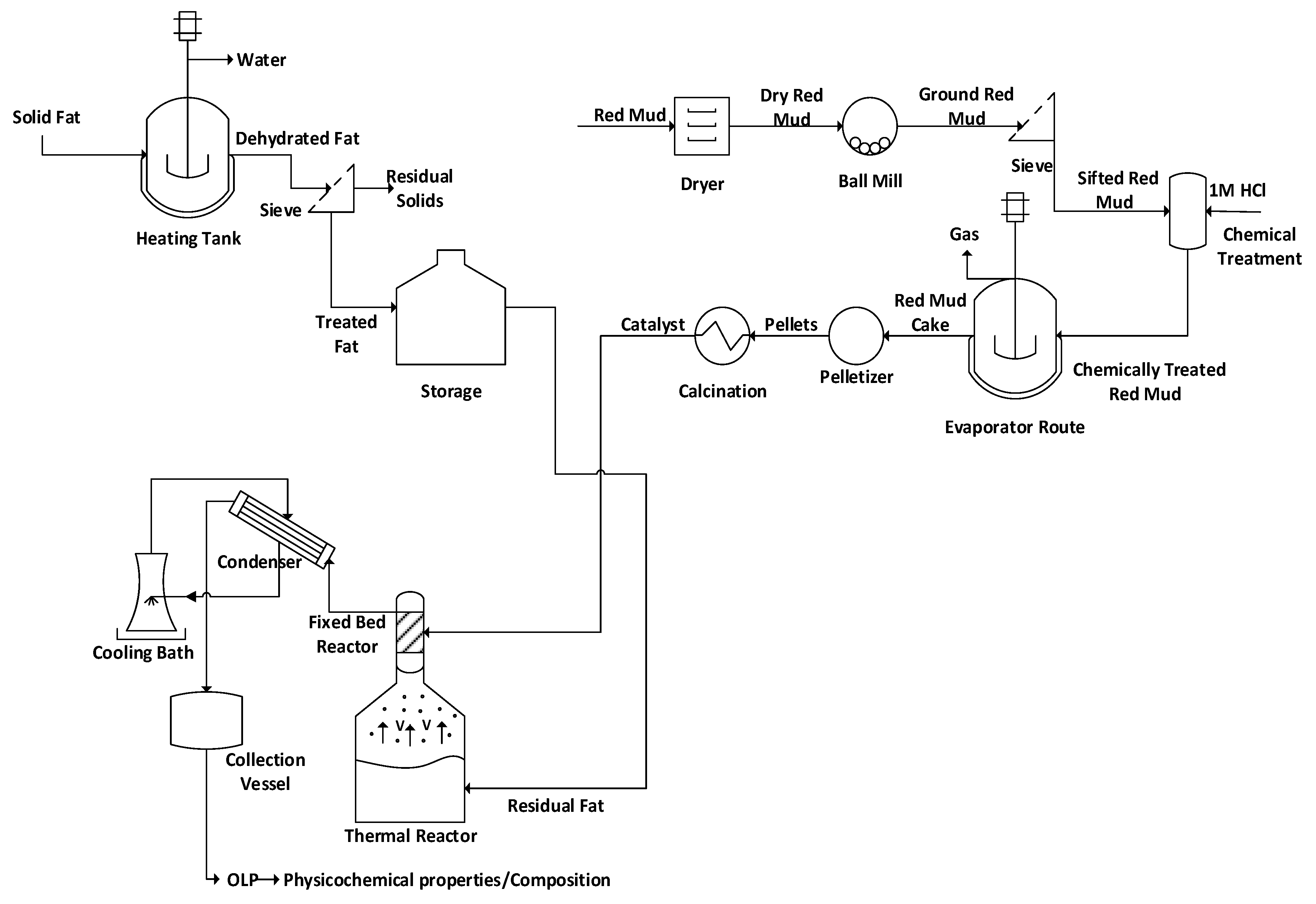
Figure 1. Process flowsheet by the production of hydrocarbon liquid mixtures by thermal cracking and thermal catalytic cracking of residual fat at 450 °C, 1.0 atm, 5.0, 7.5, and 10.0% (wt.) of red mud pellets activated with 1.0 M HCl, using a catalyst fixed bed reactor, in semi pilot scale.
Energies 15 05595 g001
Figure 2. Thermal catalytic cracking unit with a pyrolysis reactor (R-1) and a fixed bed reactor (R-2) in semi-pilot scale.
Energies 15 05595 g002
Figure 3. Schematic diagram of bench scale stainless steel catalytic cracking reactor with a pyrolysis/batch reactor and a fixed bed catalytic reactor.
Energies 15 05595 g003
Figure 4. Material after drying, milling and sieving process of red mud (a); dried red mud (b); comminuted red mud (c); and sieved red mud (d).
Energies 15 05595 g004
Figure 5. Processing of pre-treated red mud fine powders with 1.0 M HCl solution. Red mud fine powders mixed with 1.0 M HCl solution (a); and red mud pasty cake (b).
Energies 15 05595 g005
Figure 6. Production of activated red mud Material pellets before and after calcination. Acrylic mold (a); red mud pellets before calcination (b); and red mud pellets after calcination (c).
Energies 15 05595 g006
Figure 7. SEM of red mud pellets after calcination. MAG: 833 × (a); MAG: 3.33 k× (b); and MAG: 8.33 k× (c).
Energies 15 05595 g007
Figure 8. SEM of red mud pellets after the upgrading process at 450 °C, 1.0 atm, 70 min, with 5.0% (wt.) red mud pellets treated with 1.0 M HCl. MAG: 833 × (a); MAG: 3.33 k× (b); and MAG: 8.33 k× (c).
Energies 15 05595 g008
Figure 9. XRD of red mud pellets activated with 1.0 M HCl after calcination at 400 °C.
Energies 15 05595 g009
Figure 10. XRD of red mud pellets activated with 1.0 M HCl after the upgrading process.
Energies 15 05595 g010
Figure 11. Effect of catalyst-to-biomass ratio within the range 0.0–0.5 on the yield of bio-oil obtained through the upgrading process, compared with similar studies in the literature [9,28,29].
Energies 15 05595 g011
Figure 12. Effect of catalyst-to-biomass ratio within the range 0.5–10.0 on the yield of bio-oil obtained through the upgrading process, compared with similar studies in the literature [8,15,25].
Energies 15 05595 g012
Figure 13. Effect of reaction time on the density of bio-oil obtained through the upgrading process.
Energies 15 05595 g013
Figure 14. Effect of reaction time on the kinematic viscosity of bio-oil obtained through the upgrading process.
Energies 15 05595 g014
Figure 15. Effect of reaction time on the acidity of bio-oil by the upgrading of residual fat pyrolysis vapors at 450 °C, 1.0 atmosphere, 0.0, 5.0, 7.5, and 10.0% (wt.) of red mud pellets activated with 1.0 M HCl, using a catalyst fixed bed reactor, using a semi-pilot scale two-stage reactor of 2.0 L.
Energies 15 05595 g015
Figure 16. Effect of reaction time on chemical functions presented by the bio-oil obtained through thermal cracking of residual fat.
Energies 15 05595 g016
Figure 17. Effect of reaction time on chemical functions presented by the bio-oil obtained through the upgrading process.
Energies 15 05595 g017
Figure 18. Effect of reaction time on the content of hydrocarbons by the upgrading of residual fat pyrolysis vapors at 450 °C, 1.0 atmosphere, 0.0%, 5.0%, 7.5%, and 10.0% (wt.) red mud pellets activated with 1.0 M HCl, using a catalyst fixed bed reactor, using a semi-pilot scale two-stage reactor of 2.0 L.
Energies 15 05595 g018
Figure 19. Effect of reaction time on the content of oxygenates by the upgrading of residual fat pyrolysis vapors at 450 °C, 1.0 atmosphere, 0.0, 5.0, 7.5, and 10.0% (wt.) red mud pellets activated with 1.0 M HCl, using a catalyst fixed bed reactor, using a semi-pilot scale two-stage reactor of 2.0 L.
Energies 15 05595 g019
Table 1. Catalysts used on upgrading of pyrolysis vapors [1,2,3,4,5,6,7,8,9,10,11,12,13,14,15,16,17,18,19,21,22,24,25,26,29,32,34,35].
CatalystImpregnationReferences
Titania/Zirconia based-[1,24]
Ce[1,24]
ZrO2[24]
Ru/Ce[1]
Pd/Ce[1]
Ni[24]
Pt[24]
HZSM-5-[2,3,4,6,7,10,11,12,15,19,25]
Mo[2]
Co[3,4,7,11,15]
Mo[4]
Ni[4,7,15]
Mo/Co[3]
Ni/Co[3]
Al/Si = 25 to 100[8]
P[12]
Zn[12]
Ti[12]
Ce[25]
Hierarchical HZSM-5-[16]
La[16]
Alkaline Treated HZSM-5-[3]
Co[3]
Mo/Co[3]
Ni/Co[3]
-[6]
Zeolite-Y-[5,7,26]
Hierarchical[32]
Al[5]
5–10% Al[7]
30%–50% Fe[7]
Ce[26]
Sulfated Zirconia HZSM-5SZr 2:1 to 6:1[6]
Basic oxidesKaolin[9]
ZnO[9]
CaO[9]
MgO[24]
Modified ZSM-5-[13,26]
Ga[10]
Ni[10,14]
Mg[10]
Co[10,14]
Zn[10]
Cu[10]
Fe 0.5–8%[13]
Si/Al = 23 to 280[22]
Ce[26,34]
Silicon composite[29]
Faujasite ZeoliteNa[17]
Na0.2H0.8[17]
H[17]
AluminosilicatesHexagonal[18]
Wormhole[18]
Al-MCM-41[18]
MCM-41[19]
Beta zeoliteSi/Al = 21 to 250[21]
Activated carbon 10.0 M HCl[35]
Table 2. Percentages in mass and atomic mass of raw red mud, red mud activated at 1000 °C, red mud pellets activated with 1.0 M HCl after calcination at 500 °C and 4 h, and red mud pellets activated with 1.0 M HCl after upgrading process.
Catalyst
Red Mud [53]Red Mud 1000 °C [44]Red Mud Pellets 2.0 M HClRed Mud Pellets after 450 °C
Chemical ElementsMass
[wt.%]
Atomic Mass
[wt.%]
SDMass
[wt.%]
Atomic Mass
[wt.%]
SDMass
[wt.%]
Atomic Mass
[wt.%]
SDMass
[wt.%]
Atomic Mass
[wt.%]
SD
C15.4224.490.7613.1723.620.79---26.2038.31-
O44.7953.300.6343.7755.970.7256.1171.95-40.1844.10-
Na7.245.990.204.033.590.227.556.74-3.422.62-
Al7.975.631.703.952.990.1512.549.54-12.548.16-
Ca1.090.520.071.150.590.090.650.33-0.550.24-
Ti1.670.660.901.390.590.111.470.74-1.140.42-
Fe15.875.400.2929.0710.650.4912.644.64-11.993.77-
Si5.974.050.142.752.000.127.015.12-3.232.02-
Cl------1.470.85-0.740.37-
K------0.050.03----
V------0.060.02----
Ba------0.170.02----
SD = Standard Deviation.
Table 3. Process parameters, mass balances, and yields of reaction products (liquids, solids, H2O, and gas).
Process Parameters450 (°C)
0.0
(wt.)
5.0
(wt.)
7.5
(wt.)
10.0
(wt.)
Mass of residual fat (g)1000700700700
Cracking time (min)80808080
Initial cracking temperature (°C)395380380390
Mechanical system stirring speed (rpm)90909090
Mass of solid (Coke) (g)6660.0510.929.1
Mass of liquid (Bio-oil) (g)794.2380.79584.53594.13
Mass of H2O (g)11519.6317.4515.5
Mass of gas (g)24.81239.53104.5581.27
Yield of Bio-oil (wt.%)79.4254.4081.7684.88
Yield of H2O (wt.%)11.502.802.492.21
Yield of Coke (wt.%)6.608.601.561.30
Yield of Gas (wt.%)2.4834.2214.9411.61
Table 4. Process parameters, mass balances, and partial yields of bio-oil and H2O during the course of reaction (50–80 min) of experiment conducted without catalyst.
Process Parameters450 (°C)
0.00 (wt.)
50
(min)
60
(min)
70
(min)
80
(min)
Temperature of pyrolysis reactor (°C)410445435460
Temperature of fixed bed reactor (°C)----
Mass of H2O (g)115---
Yield of H2O (wt.%)11.5---
Mass of Bio-oil (g)294311.98176.112.15
Yield of Bio-oil (wt.%)29.431.217.61.22
Table 5. Process parameters, mass balances, and partial yields of bio-oil and H2O obtained during course of reaction (50–80 min) of experiment using 5.0% catalyst.
Process Parameters450 (°C)
5.00 (wt.)
40
(min)
50
(min)
60
(min)
70
(min)
Temperature of pyrolysis reactor (°C)400417440450
Temperature of fixed bed reactor (°C)380365405462
Mass of H2O (g)19.63---
Yield of H2O (wt.%)2.80---
Mass of Bio-oil (g)160.37109.7199.7111
Yield of Bio-oil (wt.%)22.9115.6714.241.57
Table 6. Process parameters, mass balances, and partial yields of bio-oil and H2O obtained during course of reaction (50–80 min) of experiment using 7.5% catalyst.
Process Parameters450 (°C)
7.50 (wt.)
40
(min)
50
(min)
60
(min)
70
(min)
Temperature of pyrolysis reactor (°C)374393410450
Temperature of fixed bed reactor (°C)371397465470
Mass of H2O (g)10.457--
Yield of H2O (wt.%)1.491--
Mass of Bio-oil (g)102.45197.74172.6794.22
Yield of Bio-oil (wt.%)14.6428.2524.6713.46
Table 7. Process parameters, mass balances, and partial yields of bio-oil and H2O obtained during course of reaction (50–80 min) of experiment using 10.0% catalyst.
Process Parameters450 (°C)
10.0 (wt.)
50
(min)
60
(min)
70
(min)
80
(min)
Temperature of pyrolysis reactor (°C)375403423450
Temperature of fixed bed reactor (°C)394404428455
Mass of H2O (g)14.11.4--
Yield of H2O (wt.%)2.010.2--
Mass of Bio-oil (g)133.86262.95113.1284.2
Yield of Bio-oil (wt.%)19.1237.5616.1612.03
Table 8. Effect of reaction time on the physicochemical properties of bio-oil obtained through the upgrading process.
Temperature/CatalysttReaction
[min]
Physical-Chemistry Properties
Ρ
[g/cm3]
I.A
[mg KOH/g]
I.R
[-]
ν [mm2/s]
450 °C500.861131.101.4459.80
600.84942.721.4586.90
700.84733.901.4606.30
800.84131.641.4455.52
450 °C, 5% red mud (wt.)400.843113.901.4444.20
500.84011.251.4583.96
600.8386.981.4733.83
700.8131.131.4393.24
450 °C, 7.5% red mud (wt.)400.871135.271.4458.45
500.857124.411.4518.39
600.84472.181.4585.30
700.8418.831.4424.46
450 °C, 10% red mud (wt.)500.874124.411.4088.10
600.85392.091.4097.78
700.84842.501.4054.10
800.82926.491.4072.80
Table 9. Bulk acid value of bio-oils obtained with and without catalyst.
ExperimentReaction Time
[min]
Weight of Bio-Oil
[g]
I.A
[mg KOH/g]
Bulk IA
[mg KOH/g]
450 °C50294.00131.1073.31
60311.9842.72
70176.1033.90
8012.1531.64
450 °C, 5% red mud (wt.)40160.37113.9053.07
50109.7111.25
6099.716.98
7011.001.13
450 °C, 7.5% red mud (wt.)40102.45135.2791.26
50197.74124.41
60172.6772.18
7094.228.83
450 °C, 10% red mud (wt.)50133.86124.4180.63
60262.9592.09
70113.1242.50
8084.2026.49
Table 10. Carbon chain length distribution of liquid bio-oil obtained through thermal cracking and catalytic upgrading with 5.0% red mud pellets fixed bed, reaction time of 20 min.
Compounds0.0% (No Fixed Bed) [%.Area]5.0% [%.Area]
C5-C102.616.6
C11-C1534.948.3
C16+62.435.1
Table 11. Chemical functions present in liquid bio-oil obtained through thermal cracking and catalytic upgrading with 5.0% red mud pellets fixed bed, reaction time of 20 min.
Chemical Function0.0% [%.Area]5.0% [%.Area]
Alkanes27.8542.96
Alkenes20.8941.05
Cyclic compounds9.856.19
Carboxylic acids20.990.00
Ketones18.428.02
Aldehydes0.000.86
Alcohols2.000.92
Total100.00100.00
Publisher’s Note: MDPI stays neutral with regard to jurisdictional claims in published maps and institutional affiliations.