Article

Co-Firing of Refuse-Derived Fuel with Ekibastuz Coal in a Bubbling Fluidized Bed Reactor: Analysis of Emissions and Ash Characteristics

1
Department of Chemical and Materials Engineering, School of Engineering and Digital Sciences, Nazarbayev University, Astana 010000, Kazakhstan
2
Department Mechanical and Aerospace Engineering, School of Engineering and Digital Sciences, Nazarbayev University, Astana 010000, Kazakhstan
*
Author to whom correspondence should be addressed.
Energies 2022, 15(16), 5785; https://doi.org/10.3390/en15165785
Submission received: 11 July 2022 / Revised: 25 July 2022 / Accepted: 27 July 2022 / Published: 9 August 2022
(This article belongs to the Special Issue New Challenges in Waste Biomass)

Abstract

:
Converting municipal solid waste (MSW) into valuable feedstocks, such as refuse-derived fuel (RDF), is a sustainable method according to the concept of waste management hierarchy. A heterogeneous composition with a good calorific value and lower emissions allows RDF to be used for energy recovery purposes. We have earlier analyzed the generation and thermochemical characteristics of the MSW produced in Kazakhstan. This work aims to study the combustion characteristics in terms of emissions and ash composition to evaluate the possibility of RDF co-firing with Ekibastuz coal. In particular, RDF is blended with high ash bituminous coal (Ekibastuz coal) and co-fired in the laboratory scale bubbling fluidized bed reactor (BFB) at a bed temperature of 850 °C. The co-firing tests of RDF to coal samples were conducted under various proportions to analyze flue gas compositions. Experiments were carried in the presence of bed material (sand), and the fuel particles were fed in batch mode into the hot riser. The BFB reactor had a height of 760 mm and internal diameter of 48 mm. The gaseous products in the flue gas were analyzed by FTIR spectrometry (Gasmet Dx4000). Ash composition was examined by XRD, XRF, SEM, and PSD. The results showed that a high RDF content decreased SO2 emissions to 28 ppm, while it negatively affected NOx release to 1400 ppm, owing to excess air. The emissions of gases from different blended samples and mineral transformations were investigated and discussed in this study.

1. Introduction

Waste-to-energy (WtE) technologies have great importance in the world of unconscious consumption of goods and their production. The aim of the WtE technology aligns well with the waste management hierarchy and enables to reduce municipal solid waste volumes while providing energy. Although these technologies are still developing, there are four main thermochemical conversion technologies for waste treatment, that is, waste-to-energy, gasification, pyrolysis, and plasma treatment [1]. Each of these technologies requires different processes and operating modes, resulting in different products and byproducts. Pyrolysis and gasification are typically used to retrieve chemicals from a wide range of wastes, while waste to energy is a viable option to obtain the energetic value of wastes. The importance of energy recovery has been highlighted earlier in several studies [1,2,3,4,5]. Gaziantep, the sixth largest city in Turkey, for example, has been using landfill gas in gas engines, which supplies 1.25% of the total power demand of the city [1]. Tsai et al. [4] also reported mitigation of CO2 emission at around 1.9 Mt and the economic benefits at around USD 150 mln from selling electricity after the construction of MSW incineration facilities in Taiwan. Hossain et al. [2] analyzed data for Bangladesh and reported that MSW incineration facilities and landfill gas recovery technologies have generated 186.4 MWh/day of electricity. Zsigraiova et al. [3] also suggested that the application of MSW incineration would be an alternative solution to generate power of 3.3–4.7 MW with 5540–6650 m3/day of drinkable water in island communities. A recent study showed that RDF could be used as alternative fuel while reducing 2155.3 × 106 Kt CO2/year [6]. Although waste incineration could generate harmful flue gases and heavy metal compounds, it still can be an environmentally friendly technology if proper cleaning systems, control of emissions, and ash disposal technology are provided. Several waste incineration technologies are commercially available including grate furnace, rotary kiln, and fluidized bed [7]. Fluidized bed technology has been used for the conversion of a wide range of solid fuels and has advantages over grate furnace as it allows to operate under blended solid fuels such as RDF with coal or biomass with coal [7]. Most grate incinerators create a cross-current mode of contact, which causes a noxious odor of the emitted gases [8]. However, this can be easily handled in fluidized bed incinerators thanks to the presence of high gas velocities and good mixing conditions. Moreover, fluidized bed technology has a simple construction, which allows flexible use of any fuel type with comparatively significant combustion efficiency at a lower temperature [9].
In Kazakhstan, public utility companies perform the separation of recyclables such as plastics, cardboards, batteries, and electronic wastes in most cities. However, sanitary landfilling remains as the main method of MSW disposal [10]. Currently, the total volume of accumulated MSW in Kazakhstan has exceeded 100 million tons [11]. According to the Association of Environmental Organizations of Kazakhstan, the country annually generates about 4–6 million tons of MSW, with a recycling rate of 18.3% [11,12]. Based on data from 2018, the generation of MSW was 1300 tons/day in the capital city, Nur-Sultan. Detailed data on MSW composition from Nur-Sultan city were obtained during several sampling campaigns and can be found in our earlier work [13,14,15].
As investigated by Abylkhani et al. [16], the potential for RDF extraction from MSW can reach up to 10 wt.%. Thus, the production of RDF from MSW is highly beneficial considering its high calorific value and ease of storage and transportation. There are a number of studies on RDF composition [17,18,19,20]. Abylkhani et al. [16] revealed that the moisture content of solid RDF in MSW of Nur-Sultan city was lower in comparison with the literature data; however, the RDF fraction showed calorific values of around 20–23 MJ/kg, which allow its potential usage in WtE technologies. Considering the high calorific values, co-firing RDF with the high ash bituminous coal in existing power plants is an attractive option to subdue emissions and economic issues. Wan et al. carried out co-firing of RDF with bituminous coal in a circulating fluidized bed (CFB) and reported a decrease in SOx and NOx emissions with an increasing RDF fraction in the feedstock [21]. Similar results were also observed by Wei et al. [22]. However, in their analysis, the concentration of HCl increased with increasing RDF fractions. Another study by Isaac and Bada [23] with TGA-based combustion showed that a blend of RDF with coal decreases the ignition and combustion temperature of volatile matters. Several such studies have summarized that co-combustion of RDF with solid fuels could be extremely effective as it lowers the formation of corrosive deposits and lessens the toxicity of emissions compared with pure combustion of RDF [24,25]. Ghani et al. observed a co-combustion efficiency of 90%, in the presence of 70% coal fraction [26]. Several co-firing studies were also conducted by All-Russia Thermal Engineering Institute [27]. The authors have observed that compounds contained in the biomass ash tend to capture SO2 produced mainly from coal. Thus, this feature even allows co-firing technology in CFB to outweigh the demand for limestone that has been traditionally used to capture SO2 too.
The formation of solid by-products from co-firing of RDF, in particular, bottom and fly ash residues, is another environmental issue, and requires better knowledge for safe disposal. It has been found that the presence of aluminum and silica compounds in the ash, alkali, and alkali-earth metal compounds can cause slagging and corrosion problems [28,29,30]. The study by Maj et al. has shown that corrosion spots contain chlorine and alkaline metals after co-firing of RDF with coal [31]. Sciubidlo et al. presented the ash characteristics of 40% of RDF fraction within the coal and observed the presence of quartz, anhydrite, illite, iron oxide, and magnetite [32]. Another recent publication determined ash with more than 8000 µg/kg of mercury, captured from flue gases [33]. Therefore, it is necessary to obtain more relevant information on ash characterization and fusion after co-firing RDF with coal.
Kazakhstan set waste management as one of the goals to hit total decarbonization in 2060. However, it is important to mention that Ekibastuz coal currently covers all heat and power needs of the north, central, and south parts of the country and some parts of Russia. Unfortunately, at present, there is no information on the conversion of Ekibastuz coal with RDF samples in fluidized bed, produced in Kazakhstan. Therefore, this study discusses the combustion characteristics and formation of by-products from co-firing of RDF with bituminous Ekibastuz coal.

2. Materials and Methods

2.1. Fuels Samples and Bed Materials

RDF fractions were collected from the MSW landfill of Nur-Sultan city during 2019. The sampling procedure was reported in our earlier work [16]. After the separation of recyclables, the second step of sorting was performed to collect smaller sizes of MSW fractions including mixed paper, mixed plastic, textile, and wood. The constituents and composition of the RDF sample were as follows: mixed paper 37.8%, mixed plastic 53.3%, textile 8.9%, and traces of wood [14]. The collected fractions of mixed paper, plastic, and textiles were further treated in the garden shredder followed by a further size reduction step in a knife mill to obtain homogenized particles with sizes between 400 and 1600 μm. The treated RDF samples are shown in Figure 1. Pellets of RDF samples were prepared in an agricultural granulator (Agrotechservice-12, Kazakhstan).
Coal samples were originally from the Ekibastuz coal mine in the north region of Kazakhstan and were delivered from the combined heat and power plant of Nur-Sultan city. The chemical characteristics of the RDF and Ekibastuz coal are presented in Table 1. The coal used in the experiments was sieved and particle sizes of 400–800 μm were used for the tests. Proximate analysis of samples was carried out according to the ASTM standard (D1762-84). Elemental analysis was performed by a CHNS analyzer (Vario Micro Cube, Elementar). The calorific values of the samples were determined in a bomb calorimeter with weights of samples ranging between 0.3 and 1.0 g. Silica sand with a mean particle size of 275 μm was used as bed material for the bubbling bed reactor with a total weight of 400 g.

2.2. Experimental Setup

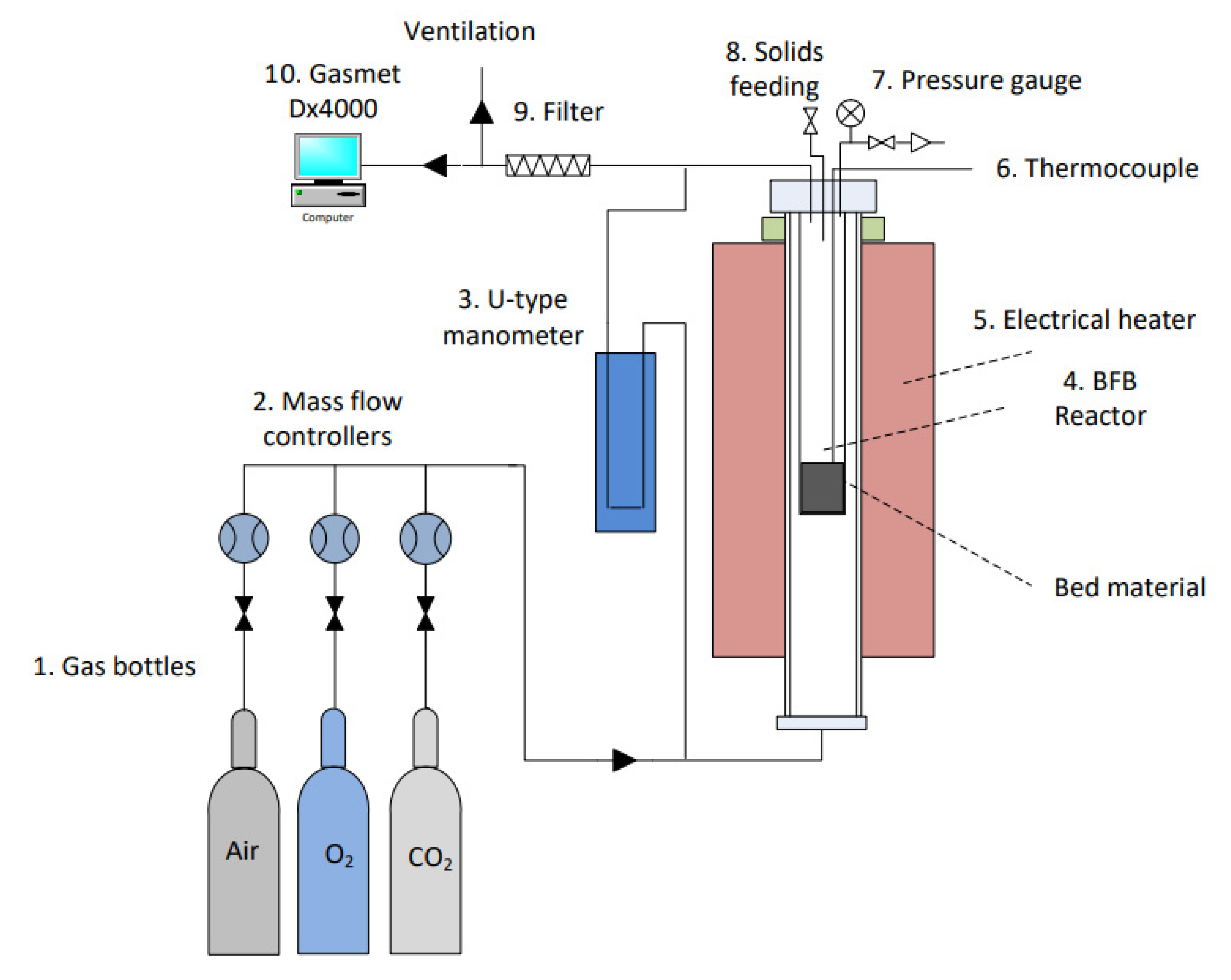
Experiments were conducted in a lab-scale bubbling fluidized bed (BFB) reactor as illustrated in Figure 2. The BFB set-up was heated electrically (Nabertherm, Lilienthal, Germany) and consisted of vertical tubes, a fuel feeding part, a gas supply system, pressure controllers, a metallic filter with stainless steel mesh for capturing fly ash, and an exit gas analysis system (Gasmet Dx4000).
The riser of the fluidized bed was made of inner and outer stainless-steel tubes. The height of the inner tube was 760 mm and its inner diameter (ID) was 48 mm, while the outer tube had a height of 1000 mm and inner diameter of 89 mm. The distributor plate was made of stainless steel (316) mesh with two layers placed at the bottom of the inner tube and clamped with an open cap. Primary air entered the bed from the bottom of the reactor. Secondary air was used for pneumatic transportation of a batch of solid fuel samples. The fuel feeding was managed mechanically by feeding the batch from the top of the riser. The secondary stream of air was essential, considering the low density of RDF, which prevented the gravity-based flow of the RDF samples into the dense zone of the bed. The products emitted from the combustion chamber were captured in the metallic filter. Exit gases were measured by an FTIR analyzer at a constant temperature of 180 °C.

2.3. Experimental Procedure

The operating conditions of the experiments are given in Table 2. Experiments were conducted at the bed temperature of 850 °C and atmospheric pressure. At typical fluidizing conditions, the volumetric flow rate of the primary air was at 3.5 L/min at 850 °C (corresponding to Umf ~ 0.0645 m/s) and the secondary air was maintained at 3.0 L/min. In addition to combustions with pure coal and RDF, experiments were performed for samples containing a 1:1 and 1:9 weight ratio of RDF to coal. Bottom ash and fly ash samples with RDF to coal ratio of 1:1 (denoted as BA-1 or FA-1) and samples with a ratio of 1:9 (denoted as BA-9 or FA-9) were collected after each experiment.
The pressure drop across the bed, measured by a U-tube manometer, was maintained steady within 1.0–1.5 kPa during the experiments. The reaction of solid fuels with air was also detected by an increase in the bed temperature of 5–10 °C. The particle size distribution of the ash samples was analyzed by a Malvern laser size analyzer (Mastersizer 3000, Malvern Panalytical Ltd., Malvern, UK). The chemical composition of the ash was further investigated by X-ray fluorescence (Panalytical Epsilon 4). The crystallinity of ash samples was determined by X-ray diffractometer (XRD) (Rigaku SmartLab, Rigaku, Tokyo, Japan) with Cu Kα radiation at a scan rate of 0.05°/s from 5° to 90° on a 2θ scale. Weight loss characteristics of ash samples were obtained by thermal gravimetrical analysis (TGA) (Perkin Elmer STA 6000, PerkinElmer, Waltham, MA, USA). Thermogravimetric experiments were carried out at the heating rate of 20 °C/min starting from a room temperature to 900 °C in air. Ash morphology was further evaluated by scanning electron microscopy (SEM, JEOL JSM-IT200LA). Before analysis, ash samples were covered with gold particles to enhance electric conductivity.

3. Results and Discussion

3.1. Exit Gas Measurements

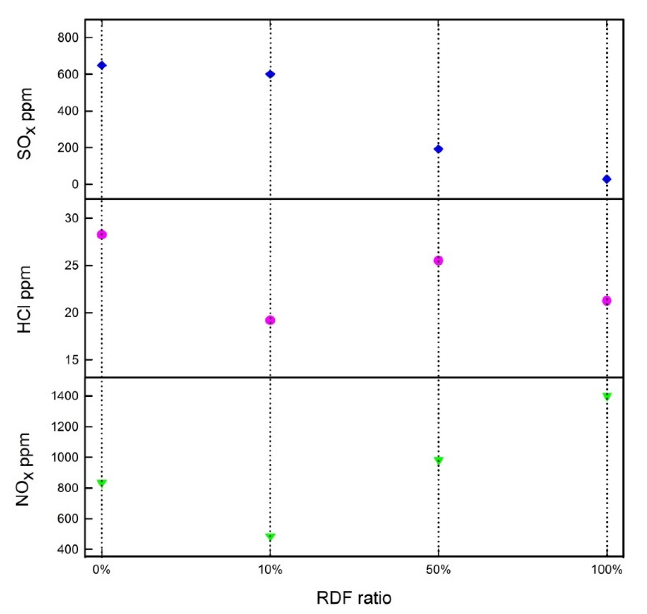
The gas analyzer measured the concentrations of CO, HCl, NOx, and SO2 on the basis of part per million (ppm), while O2 and CO2 were provided on a volume basis. Figure S1 shows the formation of CO2, CO, and O2 during the batch feeding of the fuels (coal, RDF, and two mixtures at 10% and 50% RDF). The results reveal that CO and CO2 compositions were approximately ~5000 ppm and ~21% for the coal combustion. In contrast, in the case of RDF combustion, the CO and CO2 emissions were ~25,000 ppm and ~15%, respectively. Interestingly, in the case of 10% RDF fuel, the CO2 composition was ~7% and CO was ~12,000 ppm on average, whereas 50% RDF fuel showed 7% CO2 and ~42,000 ppm of CO. One of the reasons for the increase in CO emissions could be the comparatively larger size of RDF, which caused a low combustion efficiency. Figure 3 shows the average concentrations of flue gas compositions (peak values) from several batch experiments. A linear change in the concentration of SO2 can be observed with the addition of RDF. Emission of NOx, on the other hand, showed significant fluctuations in concentrations and a drop in the combustion in RDF and coal samples with a ratio of 1:9, i.e., at 10% RDF fraction. The concentration of HCl is low compared with other emissions and remained approximately constant.
The first step in co-firing of RDF and coal could be described as follows:
RDF/coal → volatiles + char
Considering the non-homogeneous nature of RDF samples, which contain paper, plastic, textile, and wood, the following scheme could be suggested:
Wood → C6H12O6
Mixed paper → C6H12O6
Mixed plastic → (C2H4)n + (C2H3Cl)n + (C10H8O4)n
Textile → (C6H10O5)n + [C6H7O2(OH)(OCOCH3)2]n + (C10H8O4)n
Cellulose is the main component along with polyethylene, polyvinylchloride, polyether, and other artificial derivatives of cellulose in RDF. Consequently, the composition of volatiles is dominated by the production of hydrocarbons, followed by the high production of CO. The production of CO and CO2 can be presented in the following scheme [34]:
C + 0.5 O2 → 0.5 (C − O2)m → C(O)m → C(O)1 (+C) → CO and CO2
RDF has a higher content of volatile matter in comparison with coal, which leads to a sharp release of volatiles and high CO concentrations. In addition, another reason for the high CO concentration could be a longer hold-up time (residence time 5.89 s) of char particles in the freeboard region. A release of nitrogen in coal can occur via devolatilization or can remain in the char. There are over 250 possible reaction mechanisms that present the formation of N-containing products [8]. The fuel-N conversion reactions, which typically lead to thermal NOx formation, can be described by Zeldovich mechanisms [34].
Nitrogen itself was in a low concentration in either RDF or coal. However, the formation of NOx increased as the RDF co-firing ratio increased. Wan et al. [21] reported that an increase in the RDF ratio did not significantly affect the NOx emission. In particular, Wan et al. performed co-firing of bituminous coal with RDFs, containing only papers, in a circulating fluidized bed reactor. The authors report a decrease in SO2 concentration from ~180 ppm to ~160 ppm with increasing RDF content from 0 to 30%. NO2, on the other hand, remained constant ~80 ppm. There was other evidence showing no notable decrease in NOx emissions [25]. From our observation, the generation of a high amount of NOx can be evidence of less NO reduction owing to a lower amount of coal and, consequently, the char content [21]. More interestingly, the co-firing of coal with RDF leads to a reduction in SO2 concentrations, particularly due to the low sulfur content in RDFs. The concentration of SO2 was recorded as 650 ppm in coal combustion, while RDF combustion showed more than 20-times lower value of 28 ppm (Figure 3). In the tests with an RDF/coal blend of 1:1 ratio, the SO2 concentration decreased to 193 ppm. Importantly, even with the addition of 10% RDF, the SO2 concentration decreased to 602 ppm, which is lower than the combustion of pure coal.
The content of chlorine was higher in coal in comparison with RDF. However, there was no significant change in the release of HCl during all of the experiments. Blended samples fluctuated at around 19–25 ppm. In comparison, during pure coal and pure RDF combustion, HCl was determined to be 28 ppm and 21 ppm, respectively.

3.2. Ash Analysis with TGA

The thermogravimetric curves of bottom and fly ashes are shown in Figure 4a–f, respectively. The first detected peaks between 100 and 150 °C are related to moisture. It was seen that a major weight loss occurred between 250 and 600 °C in all samples, which relates to the burn-out of residual carbons and oxidation of leftover organic substances. An intense weight loss was observed in the samples of fly ashes in comparison with bottom ashes. Moreover, TG curves of fly ash residues (Figure 4d–f) showed peaks characterized by exothermic reaction. Both peaks could be attributed to unburnt carbon and mineral decomposition in the ash samples. Residual bottom ash samples have resulted in different thermal behavior compared with the fly ash samples. The bottom ash of RDF samples showed significantly lower losses as compared with others. According to PSD data, bottom ash has a higher volume density, which could cause around 10% of weight loss. The residue at 900 °C was about 90% of the original sample weight.

3.3. Characterization of Ashes

Figure 5 illustrates the results of particle size distribution (PSD) analysis of the bottom ash (BA) and fly ash (FA) samples obtained after the experiments. The particle size distributions of bottom ash samples were larger than the fly ash samples because fly ash particles go through attrition from the dense zone. The median particle sizes (D50) of the bottom ash samples BA, BA-1, and BA-9 were 216 µm, 76.1 µm, and 64.4 µm, respectively, which were significantly larger than those of the FA, FA-1, and FA-9 samples (12.7 µm, 8.84 µm, and 11.3 µm, respectively).
The results of the XRF analysis are presented in Figure S2 (Supplementary Materials). It was observed that silica, aluminum, calcium, and iron oxides were the main dominant compounds in the samples of bottom and fly ashes. In addition, other compounds such as magnesium, chromium, titanium, and sulfur oxides, as well as traces of potassium, phosphorus, and manganese oxides, were also present. It is noteworthy that all samples have a notable content of CaO. Particularly, a higher content of CaO was found in fly ash residues in comparison with bottom ash. Based on ASTM C618-19, the fly ash samples from all tests were classified as class F, which indicates the presence of pozzolanic characteristics of the fly ash. It is obvious that calcium-containing compounds devolatilize during combustion and the oxide of calcium forms after the decomposition of middle-stage compounds [29]. The presence of S and Cl components indicates that there was vaporization of sulfate and chloride compounds as well. Particularly, it is obvious that the fly ash samples showed some signs of forming Cl- and S-containing gaseous compounds.
Bottom ash samples contain mainly non-volatile elements (Al2O3, SiO2, and Fe2O3), whereas all variations of compounds (TiO2 and Cr2O3) were trapped by fly ash samples. It was found that, in the samples of BA-9, the concentrations of sulfur, aluminum, and silica oxides are higher owing to an initially larger coal content. Conversely, the formation of iron and calcium oxides was low in BA-9 residuals. The results corresponded with XRD results, which showed the presence of SiO2, Fe2O3, and silicates of alumino-calcium. It was further observed that a higher RDF fraction in the sample leads to a higher concentration of iron and calcium oxides in the bottom and fly ash samples.
Data from XRD spectrograms were further analyzed by X’Pert HighScore Plus software. The examinations showed the aluminosilicate glass phase (quartz, mullite) with iron oxides being the most abundant components in the bottom and fly ash samples. In contrast to this, the fly ash samples showed the presence of sulfates and non-silicate minerals such as calcium oxide. This could be explained by the formation of non-mineral inorganic elements from RDF.
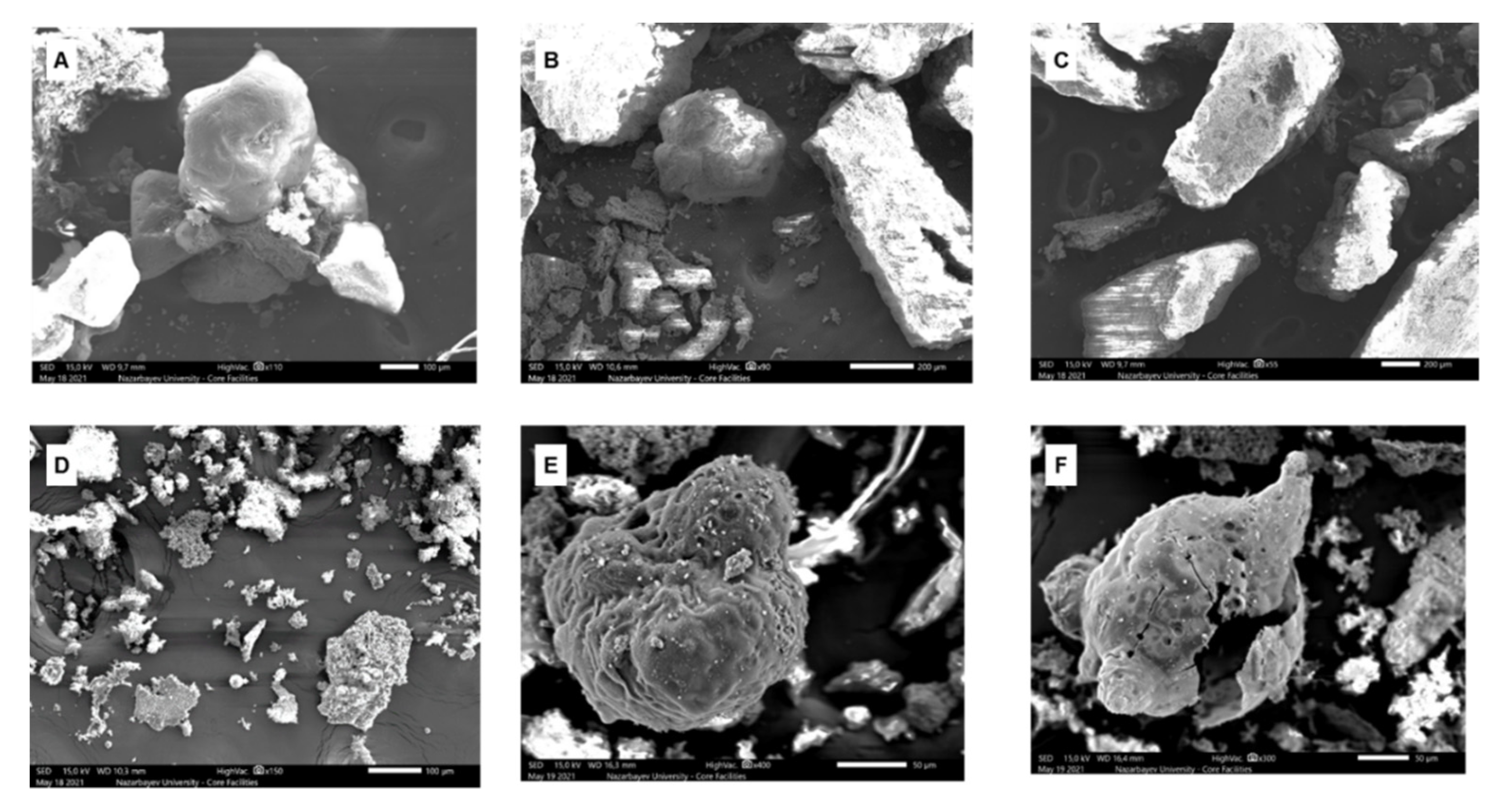
Figure 6 shows SEM images of bottom and fly ashes after RDF co-firing with Ekibastuz coal in different ratios. Moreover, EDX analyses have also been carried out to determine the localization of elements on the surfaces (Figure S3 in Supplementary Materials). The microscopic observations of the bottom ash residues showed larger particles compared with fly ash residues. It was observed that the bottom ash samples have a tendency towards the formation of spherical particles as the ratio of RDF increases in the fuel. As shown in Figure 6C, the sample with a high coal content reveals sharp and irregular-shaped residues. SEM images also illustrate that the bottom ash residues are particles made of porous layers, creating a dense morphology (Figure 6A–C).
The fly ash residues appeared as a blend of irregular fine particles. The fly ash particles shown in Figure 6D,E have an abundant pore structure. Particularly, in Figure 6F, the particle is spherical with a hollow inside. The formation of different surface morphologies of bottom ash and fly ash could be related to coal maceral composition as well as RDF composition. It is known that Ekibastuz coal belongs to the vitrinite-inertinite classification [35]. The presence of abundant porous morphologies indicates that RDF underwent volatilization and solid–liquid phase transitions. Moreover, it is more likely that the ash particle shown in Figure 6C,F is derived from vitrinite, as this fraction of Ekibastuz coal has a high fluidity property.
The EDX results show that the main elements were O, Al, Si, and Ca on the surfaces of BA and FA samples. It can be seen from Figure S3 (Supplementary Materials) that calcium is a more abundant element compared with other alkaline metals. However, small grains on the FA samples’ surface showed the presence of K, Cl, Al, Si, and O. The data presented also indicate the presence of chlorine in fly ash residue. Another interesting observation is the higher concentration of calcium in RDF bottom and fly ash samples. It can be described by the low concentration of calcium in Ekibastuz coal. To compare fly ash with bottom ash, it was observed that fine particles were usual in the samples of fly ash, which was consistent with the results of the particle size distribution analysis. This observation could be explained by the occurrence of agglomeration and fusion phenomena. Overall, the fine and brittle structure of fly ash shows that it had undergone a severe combustion process.

4. Conclusions

This study characterized the co-combustion of RDF and bituminous coal (from the Ekibastuz region) in the laboratory scale bubbling fluidized bed reactor. Several findings could be highlighted below:
(i)
A higher RDF content decreased SO2 emissions, while it negatively affected NOx release, which could be due to the presence of excess air;
(ii)
The concentration of HCl remained constant in our experiments. However, the content of chlorides may vary according to RDF compositions;
(iii)
The produced fly ash characteristics have shown the category of class F based on ASTM C618-19 standard, which means that the generated ash products may have pozzolanic activities and can be used in construction industries;
(iv)
The chemical composition of ash residues showed the presence of CaO along with aluminosilicates.
However, further research is needed on a pilot scale to explore RDF’s combustion behavior in co-firing. In addition, evaluation of the corrosion rate in the CHP plant to lessen corrosion damage needs further investigation.

Supplementary Materials

The following supporting information can be downloaded at https://www.mdpi.com/article/10.3390/en15165785/s1. Figure S1. Time-evolution of emissions of CO2, CO and O2 during batch feeding of fuel at different RDF fractions a—coal; b—RDF; c—RDF:coal at 10% RDF (1:9); d—RDF: coal at 50% RDF (1:1). Figure S2. Chemical composition of bottom and fly ash residues based on XRF analysis. Figure S3. EDX results of BA, BA-1, BA-9 (A–C) and FA, FA-1, FA-9 (D–F).

Author Contributions

Conceptualization, B.S. and D.Z.; methodology, B.S.; software, D.Z.; validation, B.S., D.Z. and B.A.; formal analysis, B.S.; investigation, B.S. and B.A.; writing—original draft preparation, B.S.; writing—review and editing, D.S. and Y.S.; visualization, D.S.; supervision, D.S. and Y.S.; project administration, D.S. and Y.S., funding acquisition, D.S. and Y.S. All authors have read and agreed to the published version of the manuscript.

Funding

This research was funded by Nazarbayev University, grant number 11022021FD2918 (Thermochemical conversion of flax straw agricultural waste produced in Kazakhstan) and 11022021FD2905 (Efficient thermal valorization of municipal sewage sludge in fluidized bed systems: Advanced experiments with process modeling).

Informed Consent Statement

Not applicable.

Conflicts of Interest

The authors declare that they have no known competing financial interests or personal relationships that could have appeared to influence the work reported in this paper.

References

  1. Tozlu, A.; Özahi, E. Waste to Energy Technologies for Municipal Solid Waste Management in Gaziantep. Renew. Sustain. Energy Rev. 2016, 54, 809–815. [Google Scholar] [CrossRef]
  2. Hossain, H.M.Z.; Hasna, Q.; Uddin, M.; Ahmed, T. Municipal Solid Waste (MSW) as a Source of Renewable Energy in Bangladesh: Revisited. Renew. Sustain. Energy Rev. 2014, 39, 35–41. [Google Scholar] [CrossRef]
  3. Zsigraiova, Z.; Tavares, G.; Semiao, V.; de Grac, M. Integrated Waste-to-Energy Conversion and Waste Transportation within Island Communities. Energy 2009, 34, 623–635. [Google Scholar] [CrossRef]
  4. Tsai, W.; Kuo, K. An Analysis of Power Generation from Municipal Solid Waste (MSW) Incineration Plants in Taiwan. Energy 2010, 35, 4824–4830. [Google Scholar] [CrossRef]
  5. Wang, L.; Hu, G.; Gong, X.; Bao, L. Emission Reductions Potential for Energy from Municipal Solid Waste Incineration in Chongqing. Renew. Energy 2009, 34, 2074–2079. [Google Scholar] [CrossRef]
  6. Shehata, N.; Obaideen, K.; Sayed, E.T.; Abdelkareem, M.A.; Mahmoud, M.S.; El-Salamony, A.L.H.R.; Mahmoud, H.M.; Olabi, A.G. Role of Refuse-Derived Fuel in Circular Economy and Sustainable Development Goals. Process. Saf. Environ. Prot. 2022, 163, 558–573. [Google Scholar] [CrossRef]
  7. Neuwahl, F.; Cusano, G.; Benavides, J.G.; Holbrook, S.; Roudier, S. Best Available Techniques (BAT) Reference Document for Waste Incineration; Publications Office of the European Union: Luxembourg, 2019. [Google Scholar]
  8. Oka, S. Fluidized Bed Combustion; Marcel Dekker, Inc.: New York, NY, USA, 2004. [Google Scholar]
  9. Robl, T.; Oberlink, A.; Jones, R. Coal Combustion Products (CCPs) 1st Edition Characteristics, Utilization and Beneficiation; Woodhead: Sawston, UK, 2017; ISBN 9780081009451. [Google Scholar]
  10. Sarbassov, Y.; Sagalova, T.; Tursunov, O.; Venetis, C. Survey on Household Solid Waste Sorting at Source in Developing Economies: A Case Study of Nur-Sultan City in Kazakhstan. Sustainability 2019, 11, 6496. [Google Scholar] [CrossRef] [Green Version]
  11. Strategy 2050 MSW Utilization: How Situation Has Been Improved over the Past Year. Available online: https://strategy2050.kz/ru/news/utilizatsiya-tbo-naskolko-uluchshilis-pokazateli-za-posledniy-god/ (accessed on 2 July 2022).
  12. Information on Reduction, Recycle and Utilization of Wastes. Available online: https://egov.kz/cms/ru/articles/ecology/waste_reduction_recycling_and_reuse (accessed on 2 July 2022).
  13. Abylkhani, B.; Guney, M.; Aiymbetov, B.; Yagofarova, A.; Sarbassov, Y.; Zorpas, A.A.; Venetis, C.; Inglezakis, V. Detailed Municipal Solid Waste Composition Analysis for Nur-Sultan City, Kazakhstan with Implications for Sustainable Waste Management in Central Asia. Environ. Sci. Pollut. Res. 2020, 28, 24406–24418. [Google Scholar] [CrossRef]
  14. Kuspangaliyeva, B.; Suleimenova, B.; Shah, D.; Sarbassov, Y. Thermogravimetric Study of Refuse Derived Fuel Produced from Municipal Solid Waste of Kazakhstan. Appl. Sci. 2021, 11, 1219. [Google Scholar] [CrossRef]
  15. Sarbassov, Y.; Venetis, C.; Aiymbetov, B.; Abylkhani, B.; Yagofarova, A.; Tokmurzin, D.; Anthony, E.J.; Inglezakis, V.J. Municipal Solid Waste Management and Greenhouse Gas Emissions at International Airports: A Case Study of Astana International Airport. J. Air Transp. Manag. 2020, 85, 101789. [Google Scholar] [CrossRef]
  16. Abylkhani, B.; Aiymbetov, B.; Yagofarova, A.; Tokmurzin, D.; Venetis, C.; Poulopoulos, S.; Sarbassov, Y.; Inglezakis, V.J. Seasonal Characterisation of Municipal Solid Waste from Astana City, Kazakhstan: Composition and Thermal Properties of Combustible Fraction. Waste Manag. Res. 2019, 37, 1271–1281. [Google Scholar] [CrossRef]
  17. Grammelis, P.; Basinas, P.; Malliopoulou, A.; Sakellaropoulos, G. Pyrolysis Kinetics and Combustion Characteristics of Waste Recovered Fuels. Fuel 2009, 88, 195–205. [Google Scholar] [CrossRef]
  18. Kara, M. Environmental and Economic Advantages Associated with the Use of RDF in Cement Kilns. Resour. Conserv. Recycl. 2012, 68, 21–28. [Google Scholar] [CrossRef]
  19. Reza, B.; Soltani, A.; Ruparathna, R.; Sadiq, R.; Hewage, K. Environmental and Economic Aspects of Production and Utilization of RDF as Alternative Fuel in Cement Plants: A Case Study of Metro Vancouver Waste Management. Resour. Conserv. Recycl. 2013, 81, 105–114. [Google Scholar] [CrossRef]
  20. Sorum, L.; Gronli, M.G.; Hustad, J.E. Pyrolysis Characteristics and Kinetics of Municipal Solid Wastes. Fuel 2001, 80, 1217–1227. [Google Scholar] [CrossRef]
  21. Wan, H.P.; Chang, Y.H.; Chien, W.C.; Lee, H.T.; Huang, C.C. Emissions during Co-Firing of RDF-5 with Bituminous Coal, Paper Sludge and Waste Tires in a Commercial Circulating Fluidized Bed Co-Generation Boiler. Fuel 2008, 87, 761–767. [Google Scholar] [CrossRef]
  22. Wei, X.; Wang, Y.; Liu, D.; Sheng, H.; Tian, W.; Xiao, Y. Release of Sulfur and Chlorine during Cofiring RDF and Coal in an Internally Circulating Fluidized Bed. Energy Fuels 2009, 23, 1390–1397. [Google Scholar] [CrossRef] [Green Version]
  23. Isaac, K.; Bada, S.O. The Co-Combustion Performance and Reaction Kinetics of Refuse Derived Fuels with South African High Ash Coal. Heliyon 2020, 6, e03309. [Google Scholar] [CrossRef]
  24. Zabetta, E.C.; Barisic, V.; Peltola, K.; Hotta, A. Foster Wheeler Experience with Biomass and Waste in CFBs. In Proceedings of the 33rd Clearwater Conference, Clearwater, FL, USA, 1–5 June 2008. [Google Scholar]
  25. Rigamonti, L.; Grosso, M.; Biganzoli, L. Environmental Assessment of Refuse-Derived Fuel Co-Combustion in a Coal-Fired Power Plant. J. Ind. Ecol. 2012, 16, 748–760. [Google Scholar] [CrossRef]
  26. Ghani, W.A.; Alias, A.B.; Cliffe, K.R. Co-Combustion of Refuse Derived Fuel with Coal in a Fluidised Bed Combustor. J. Eng. Sci. Technol. 2009, 4, 122–131. [Google Scholar]
  27. Ryabov, G.A.; Dolgushin, I.A. Use of Circulating Fluidized Bed Technology at Thermal Power Plants with Co-Firing of Biomass and Fossil Fuels. Power Technol. Eng. 2013, 46, 491–495. [Google Scholar] [CrossRef]
  28. Jiang, D.; Song, W.; Wang, X.; Zhu, Z. Physicochemical Properties of Bottom Ash Obtained from an Industrial CFB Gasifier. J. Energy Inst. 2021, 95, 1–7. [Google Scholar] [CrossRef]
  29. Wong, G.; Gan, M.; Fan, X.; Ji, Z.; Chen, X.; Wang, Z. Co-Disposal of Municipal Solid Waste Incineration Fly Ash and Bottom Slag: A Novel Method of Low Temperature Melting Treatment. J. Hazard. Mater. 2021, 408, 124438. [Google Scholar] [CrossRef] [PubMed]
  30. Yao, X.; Mao, J.; Li, L.; Sun, L.; Xu, K.; Ma, X.; Hu, Y.; Zhao, Z.; Chen, S.; Xu, K. Characterization Comparison of Bottom Ash and Fly Ash during Gasification of Agricultural Residues at an Industrial-Scale Gasification Plant—Experiments and Analysis. Fuel 2021, 285, 119122. [Google Scholar] [CrossRef]
  31. Maj, I.; Kalisz, S.; Wejkowski, R.; Pronobis, M.; Gołombek, K. High-Temperature Corrosion in a Multifuel Circulating Fluidized Bed (CFB) Boiler Co-Firing Refuse Derived Fuel (RDF) and Hard Coal. Fuel 2022, 324, 124749. [Google Scholar] [CrossRef]
  32. Sciubidlo, A.; Majchrzak-Kuceba, I.; Niedzielska, M. Comparison of Fly Ash from Co-Combustion of Coal/Solid Recovered Fuel (SRF) and Coal/Refuse Derived Fuel (RDF). J. Phys. Conf. Ser. 2019, 1398, 012015. [Google Scholar] [CrossRef]
  33. Mlonka-Medrala, A.; Dziok, T.; Magdziarz, A.; Nowak, W. Composition and Properties of Fly Ash Collected from a Multifuel Fluidized Bed Boiler Co-Firing Refuse Derived Fuel (RDF) and Hard Coal. Energy 2021, 234, 121229. [Google Scholar] [CrossRef]
  34. Williams, A.; Pourkashanian, M.; Jones, J.M.; Skorupska, N. Combustion and Gasification of Coal; Taylor & Francis: New York, NY, USA, 2000. [Google Scholar]
  35. Sharonova, O.M. Composition and Morphology of Char Particles of Fly Ashes from Industrial Burning of High-Ash Coals with Different Reactivity. Fuel 2008, 87, 1989–1997. [Google Scholar] [CrossRef]
Figure 1. Pretreated RDF samples and their fractions before the experiment.
Energies 15 05785 g001
Figure 2. Schematic of the lab-scale bubbling fluidized bed reactor used in cofiring of coal with RDF.
Energies 15 05785 g002
Figure 3. Time-averaged emissions of SO2, NOx, and HCl during co-firing with different ratios of RDF showing that SO2 decreased, HCl remained constant, and NOx decreased and further increased with increasing RDF fractions.
Energies 15 05785 g003
Figure 4. Thermal behaviour of BA, BA-1, and BA-9 (ac) and FA, FA-1, and FA-9 (df) indicating moisture and unburnt carbon present in the ash.
Energies 15 05785 g004
Figure 5. Particle size distribution of the (a) bottom ash (BA, BA-1, and BA-9) and (b) fly ash (FA, FA-1, and FA-9). The median particle sizes of bottom ash were 216 µm, 76.1 µm, and 64.4 µm, respectively, which were significantly larger than those of the fly ash, at 12.7 µm, 8.84 µm, and 11.3 µm, respectively.
Energies 15 05785 g005
Figure 6. SEM observations of BA, BA-1, and BA-9 (AC) and FA, FA-1, and FA-9 (DF) indicating the porous nature of the fly ash.
Energies 15 05785 g006
Table 1. Proximate analysis, ultimate analysis, and calorific values of the samples [14].
Proximate (wt%, as Received)RDFPlasticPaperTextileCoal
Moisture1.50.82.61.22.1
Volatile matter86.787.385.786.719.9
Ash8.28.78.54.038.5
Fixed carbon3.63.23.28.139.3
Ultimate (wt%, and dry ash-free)
Carbon66.583.546.847.861.2
Hydrogen9.913.06.46.13.5
Nitrogen0.60.50.61.32.1
Sulfur0.20.30.10.20.7
Oxygen *22.82.746.144.632.4
Gross Calorific value (MJ/kg) **23.432.616.420.119.37
* by difference; ** measured by bomb calorimeter.
Table 2. Experimental conditions used for co-combustion of RDF with coal.
ParametersRDFRDF/Coal Blend IRDF/Coal Blend IICoal
Particle size (mm)1–2.51–2.5/0.4–0.81–2.5/0.4–0.80.4–0.8
Temperature fluctuation during feeding (°C)7–126–106–103–5
Pressure drop (kPa)1.51.21.21.0
RDF/coal blend ratio -1:1 (50%)1:9 (10%)-
Weight of sample (g)1–1.5
Furnace temperature (°C)850
Minimum fluidizing velocity (m/s)0.0645
Primary air flow rate (L/min)3.5
Secondary air flow rate (L/min)3.0
Publisher’s Note: MDPI stays neutral with regard to jurisdictional claims in published maps and institutional affiliations.